EP3617620B1 - Abtauverfahren für abtauvorrichtung - Google Patents
Abtauverfahren für abtauvorrichtung Download PDFInfo
- Publication number
- EP3617620B1 EP3617620B1 EP18814417.4A EP18814417A EP3617620B1 EP 3617620 B1 EP3617620 B1 EP 3617620B1 EP 18814417 A EP18814417 A EP 18814417A EP 3617620 B1 EP3617620 B1 EP 3617620B1
- Authority
- EP
- European Patent Office
- Prior art keywords
- thawing
- radio frequency
- generation module
- impedance
- frequency generation
- Prior art date
- Legal status (The legal status is an assumption and is not a legal conclusion. Google has not performed a legal analysis and makes no representation as to the accuracy of the status listed.)
- Active
Links
Images




Classifications
-
- F—MECHANICAL ENGINEERING; LIGHTING; HEATING; WEAPONS; BLASTING
- F25—REFRIGERATION OR COOLING; COMBINED HEATING AND REFRIGERATION SYSTEMS; HEAT PUMP SYSTEMS; MANUFACTURE OR STORAGE OF ICE; LIQUEFACTION SOLIDIFICATION OF GASES
- F25D—REFRIGERATORS; COLD ROOMS; ICE-BOXES; COOLING OR FREEZING APPARATUS NOT OTHERWISE PROVIDED FOR
- F25D21/00—Defrosting; Preventing frosting; Removing condensed or defrost water
- F25D21/002—Defroster control
- F25D21/006—Defroster control with electronic control circuits
-
- H—ELECTRICITY
- H05—ELECTRIC TECHNIQUES NOT OTHERWISE PROVIDED FOR
- H05B—ELECTRIC HEATING; ELECTRIC LIGHT SOURCES NOT OTHERWISE PROVIDED FOR; CIRCUIT ARRANGEMENTS FOR ELECTRIC LIGHT SOURCES, IN GENERAL
- H05B6/00—Heating by electric, magnetic or electromagnetic fields
- H05B6/46—Dielectric heating
- H05B6/62—Apparatus for specific applications
-
- A—HUMAN NECESSITIES
- A23—FOODS OR FOODSTUFFS; TREATMENT THEREOF, NOT COVERED BY OTHER CLASSES
- A23B—PRESERVATION OF FOODS, FOODSTUFFS OR NON-ALCOHOLIC BEVERAGES; CHEMICAL RIPENING OF FRUIT OR VEGETABLES
- A23B2/00—Preservation of foods or foodstuffs, in general
- A23B2/80—Freezing; Subsequent thawing; Cooling
- A23B2/82—Thawing subsequent to freezing
-
- F—MECHANICAL ENGINEERING; LIGHTING; HEATING; WEAPONS; BLASTING
- F25—REFRIGERATION OR COOLING; COMBINED HEATING AND REFRIGERATION SYSTEMS; HEAT PUMP SYSTEMS; MANUFACTURE OR STORAGE OF ICE; LIQUEFACTION SOLIDIFICATION OF GASES
- F25D—REFRIGERATORS; COLD ROOMS; ICE-BOXES; COOLING OR FREEZING APPARATUS NOT OTHERWISE PROVIDED FOR
- F25D11/00—Self-contained movable devices, e.g. domestic refrigerators
- F25D11/02—Self-contained movable devices, e.g. domestic refrigerators with cooling compartments at different temperatures
-
- H—ELECTRICITY
- H05—ELECTRIC TECHNIQUES NOT OTHERWISE PROVIDED FOR
- H05B—ELECTRIC HEATING; ELECTRIC LIGHT SOURCES NOT OTHERWISE PROVIDED FOR; CIRCUIT ARRANGEMENTS FOR ELECTRIC LIGHT SOURCES, IN GENERAL
- H05B6/00—Heating by electric, magnetic or electromagnetic fields
- H05B6/64—Heating using microwaves
- H05B6/66—Circuits
- H05B6/68—Circuits for monitoring or control
- H05B6/688—Circuits for monitoring or control for thawing
Definitions
- the present invention relates to the field of thawing, and particularly relates to a thawing method for a thawing device.
- the quality of the food is maintained, but the frozen food needs to be thawed before processing or eating.
- the food is generally thawed by disposing a heating device or a microwave device in a refrigerator.
- thawing time and temperature are not easy to grasp, which is prone to water evaporation and juice loss of the food, resulting in quality loss of the food; and thawing food by means of the microwave device is fast and efficient, so that the nutrient loss of the food is very low, however, due to a difference in penetration and absorption of water and ice by microwaves and the uneven distribution of internal substances in the food, the melted regions absorb more energy, resulting in the problems of uneven thawing and local overheating.
- a thawing method for a thawing device which has high thawing efficiency, can realize uniform thawing and can ensure the food quality.
- Document DE 38 18 491 A1 discloses a thawing method according to the preamble of claim 1.
- An objective of the first aspect of the present invention is directed to provide a thawing method for a thawing device, which has high thawing efficiency, can realize uniform thawing and can ensure the food quality.
- a further objective of the first aspect of the present invention is to improve the thawing efficiency of the thawing device.
- Another further objective of the first aspect of the present invention is to prevent an object to be processed from being excessively thawed.
- An objective of the second aspect of the present invention is to provide a thawing method for a refrigerator.
- the present invention provides a thawing method for a thawing device.
- the thawing device includes a cavity defining a thawing chamber configured for placement of an object to be processed and having a forward opening, a device door disposed at the forward opening of the thawing chamber and configured to open and close the thawing chamber, a radio frequency generation module, and an upper electrode plate and a lower electrode plate horizontally disposed on a top wall and a bottom wall of the thawing chamber respectively.
- the upper electrode plate and the lower electrode plate are electrically connected with the radio frequency generation module respectively.
- the thawing method includes:
- the thawing device further includes a detection module, and the detection module is configured to detect an incident wave signal and a reflected wave signal of an electrical connection wire connecting the radio frequency generation module to the upper electrode plate.
- the thawing method includes:
- the thawing device further includes a load compensation module, and the load compensation module includes a compensation unit connected in series with the object to be processed and a motor configured to increase or reduce the impedance of the compensation unit.
- the thawing method includes:
- the radio frequency signal has a constant frequency preset in the range of 40.48 to 40.68 MHz.
- the step of enabling the load compensation module to work includes:
- a control method for the thawing device includes:
- the step of determining the thawing progress of the object to be processed includes:
- the step of determining the thawing progress of the object to be processed includes:
- a thawing method for a refrigerator includes a refrigerator body defining at least one containing space, a compartment door for opening and closing the containing space separately, and a thawing device disposed in one of the containing spaces.
- the thawing method includes any one of the above thawing methods for a thawing device.
- the refrigerator further includes a power supply module for supplying power for the thawing device, and a thawing switch for controlling the start and stop of a thawing program is disposed on any one of the compartment doors.
- the thawing method for a refrigerator includes:
- radio frequency waves using the frequency range of the present application have shorter thawing time, higher temperature-uniformity and lower juice loss rate than radio frequency waves of other frequencies, and are especially suitable for thawing devices.
- the load compensation module the difference between the load impedance of the radio frequency generation module and the output impedance of the radio frequency generation module is in a preset range (greater than or equal to a first impedance threshold and less than or equal to a second impedance threshold), thereby further improving the thawing efficiency of the object to be processed.
- the change rate of the dielectric coefficient of the object to be processed is calculated by the detection module to determine the thawing progress of the object to be processed.
- the temperature of the object to be processed is higher (i.e., the temperature of the object to be processed is greater than or equal to -7°C)
- the thermal effect is significantly attenuated, so that the object to be processed cannot be excessively thawed.
- the radio frequency thawing power is larger (greater than 100 W).
- the inventor of the present application has creatively recognized that when the temperature of the object to be processed is higher, the object to be processed can be effectively prevented from being excessively thawed by reducing the working power of the radio frequency generation module by 30 to 40%. Further, whether the thawing is completed or not is determined according to the change rate of the dielectric coefficient of the object to be processed. Compared with the mode of determining whether the thawing is completed by sensing the temperature of the object to be processed in the prior art, the determining mode of the present invention is more accurate, and the object to be processed can be further prevented from being excessively thawed.
- Tests show that the temperature of the object to be processed, thawed by the thawing device of the present invention, is generally -4 to -2°C when the thawing is completed, and bloody water generated by thawing when the object to be processed is meat can be avoided.
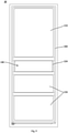
- FIG. 1 is a schematic structural view of a thawing device 100 according to an embodiment of the present invention.
- the thawing device 100 may include a cavity 110, a device door 120, a radio frequency generation module 130, an upper electrode plate 140a and a lower electrode plate 140b.
- the cavity 110 may include a top plate, a bottom plate, a rear plate and two transverse side plates opposite to each other, a thawing chamber 114 having a forward opening may be defined therein, and the thawing chamber 114 is configured for placement of an object to be processed.
- the device door 120 may be disposed at the forward opening of the thawing chamber 114 and configured to open or close the thawing chamber 114.
- the device door 120 and the cavity 110 may be mounted together through an appropriate method, such as left-hand door, right-hand door and swing-up door.
- the radio frequency generation module 130 may be configured to generate a radio frequency signal (generally a radio frequency signal having a frequency between 300 KHz and 300 GHz).
- the upper electrode plate 140a and the lower electrode plate 140b may be horizontally disposed on a top wall and a bottom wall of the thawing chamber 114 respectively and electrically connected with the radio frequency generation module 130 respectively to generate radio frequency waves of corresponding parameters in the thawing chamber 114 according to the radio frequency signal generated by the radio frequency generation module 130, and thaw the object to be processed in the thawing chamber 114.
- the upper electrode plate 140a is a transmitting antenna
- the lower electrode plate 140b is a receiving antenna.
- the upper electrode plate 140a and the lower electrode plate 140b may be electrically connected with the radio frequency generation module 130 respectively by adopting a 50-ohm electrical connection wire.
- the thawing device 100 may further include a detection module 150.
- the detection module 150 may be configured to detect an incident wave signal and a reflected wave signal of an electrical connection wire connecting the radio frequency generation module 130 to the upper electrode plate, and calculate a load impedance of the radio frequency generation module 130 according to a voltage and a current of the incident wave signal and a voltage and a current of the reflected wave signal.
- SWR standing-wave ratio
- Z 1 is output impedance
- Z 2 is load impedance
- U 1 is incident wave voltage
- I 1 is incident wave current
- R 1 is output resistance
- X 1 is output reactance
- U 2 is reflected wave voltage
- I 2 is reflected wave current
- R 2 is load resistance
- X 2 is load reactance.
- the output impedance is the impedance of the electrical connection wire connecting the radio frequency generation module 130 to the upper electrode plate 140a
- the load impedance is the impedance of the object to be processed.
- the thawing device 100 may further include a load compensation module 160.
- the load compensation module 160 may include a compensation unit and a motor for adjusting a load of the compensation unit.
- the compensation unit may be disposed in series with the object to be processed. That is, the load impedance of the radio frequency generation module 130 is the sum of the impedance of the object to be processed and the impedance of the compensation unit.
- the motor may be configured to controllably increase or reduce the load of the compensation unit to increase or reduce the load impedance Z 2 of the radio frequency generation module 130, and enable a difference (a value obtained by subtracting the output impedance Z 1 from the load impedance Z 2 ) between the load impedance Z 2 of the radio frequency generation module 130 and the output impedance Z 1 of the radio frequency generation module 130 to be greater than or equal to a first impedance threshold and less than or equal to a second impedance threshold (the first impedance threshold is less than the second impedance threshold) to improve the thawing efficiency of the object to be processed.
- the first impedance threshold is -6 to -4% of the output impedance Z 1
- the second impedance threshold is 4 to 6% of the output impedance Z 1
- the first impedance threshold is -5% of the output impedance Z 1
- the second impedance threshold is 5% of the output impedance Z 1
- the load compensation module may be configured to enable an absolute value of the difference between the load impedance Z 2 of the radio frequency generation module 130 and the output impedance Z 1 to be always less than 5% of the output impedance Z 1 in a whole thawing process, such as 1%, 3% or 5% of the output impedance Z1.
- the detection module 150 may be configured to further calculate a dielectric coefficient of the object to be processed and a change rate of the dielectric coefficient according to the load impedance Z 2 of the radio frequency generation module 130.
- f frequency of radio frequency wave
- C capacitance of a capacitor constituted by the upper electrode plate 140a and the lower electrode plate 140b
- ⁇ dielectric coefficient of the object to be processed
- K static constant
- d thickness of the upper electrode plate
- S area of the upper electrode plate.
- the change rate of the dielectric coefficient of the object to be processed can be obtained by calculating a change value ⁇ of the dielectric coefficient ⁇ within a unit time ⁇ t, where the unit time ⁇ t may be 0.1 s to 1 s, such as 0.1 s, 0.5 s or 1 s.
- FIG. 4 is a graph showing a change rate of a dielectric coefficient of an object to be processed according to an embodiment of the present invention, where the longitudinal coordinate is the change rate ⁇ / ⁇ t of the dielectric coefficient of the object to be processed, and the horizontal coordinate is the thawing time t (unit: min) of the object to be processed. Referring to FIG.
- the radio frequency generation module 130 may be configured as follows: when the change rate ⁇ / ⁇ t of the dielectric coefficient of the object to be processed is greater than or equal to the first rate threshold, the working power of the radio frequency generation module 130 is reduced by 30% to 40%, such as 30%, 35% or 40%, thereby preventing the object to be processed from being excessively thawed.
- the excessive thawing means that the temperature of the object to be processed is greater than 0°C.
- the first preset threshold may be 15 to 20, such as 15, 17, 18 or 20.
- the radio frequency generation module 130 may also be configured to: stop working when the change rate ⁇ / ⁇ t of the dielectric coefficient of the object to be processed decreases to be less than or equal to the second rate threshold.
- the second preset threshold may be 1 to 2, such as 1, 1.5 or 2.
- the dielectric coefficient of the object to be processed As the temperature of the object to be processed changes, the dielectric coefficient of the object to be processed also changes, which is well known to those skilled in the art.
- the dielectric coefficient is usually measured by a special instrument (for example, a dielectric coefficient tester), and the special instrument is large in occupied space and high in cost and is not suitable for a thawing device having a smaller size.
- the dielectric coefficient of the object to be processed is calculated by detecting the incident wave signal and the reflected wave signal of the electrical connection wire connecting the radio frequency generation module 130 to the upper electrode plate, and the radio frequency generation module 130 is small in occupied space and low in cost and is especially suitable for the thawing device.
- the change rate of the dielectric coefficient of the object to be processed is calculated by the detection module 150 to determine the thawing progress of the object to be processed.
- the temperature of the object to be processed is higher (i.e., the temperature of the object to be processed is greater than or equal to -7°C)
- the thermal effect is significantly attenuated, so that the object to be processed cannot be excessively thawed.
- the radio frequency thawing power is larger (greater than 100 W).
- the inventor of the present application have creatively recognized that when the temperature of the object to be processed is higher, the object to be processed can be effectively prevented from being excessively thawed by reducing the working power of the radio frequency generation module 130 by 30 to 40%. Further, whether the thawing is completed is determined according to the change rate of the dielectric coefficient of the object to be processed. Compared with the mode of determining whether the thawing is completed by sensing the temperature of the object to be processed in the prior art, the determining mode of the present invention is more accurate, and the object to be processed can be further prevented from being excessively thawed.
- Tests show that the temperature of the object to be processed, thawed by the thawing device of the present invention, is generally -4 to -2°C when the thawing is completed, and bloody water generated by thawing when the object to be processed is meat can be avoided.
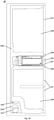
- FIG. 2 is a schematic cross-sectional view taken along a section line A-A in FIG. 1 .
- the cavity 110 may further include a vertical clapboard 111 and a horizontal clapboard 112 for defining an inner space of the cavity 110.
- the vertical clapboard 111 may be configured to extend from a top plate of the cavity 110 along a vertical direction to a bottom plate of the cavity 110.
- the radio frequency generation module 130 may be disposed between the vertical clapboard 111 and the rear plate of the cavity 110.
- the horizontal clapboard 112 may be configured to extend forward from the vertical clapboard 111 along a horizontal direction.
- the detection module 150 and the load compensation module 160 may be disposed between the horizontal clapboard 112 and the top plate of the cavity 110.
- the thawing chamber 114 may be enclosed by the vertical clapboard 111, the horizontal clapboard 112 and the bottom plate and two transverse side plates of the cavity 110.
- the upper electrode plate 140a may be disposed on the lower surface of the horizontal clapboard 112, and the lower electrode plate 140b may be disposed on the upper surface of the bottom plate of the cavity 110.
- the vertical clapboard 111 may be provided with a first wire passing port 1112, so that the radio frequency generation module 130 is electrically connected with the upper electrode plate 140a through the first wire passing port 1112.
- the cavity 110 may further include a baffle plate 113 extending upward from a front side end of the horizontal clapboard 112 along a vertical direction to the top plate of the cavity 110, to prevent the exposure of the detection module 150 and the load compensation module 160 from affecting the aesthetics of the thawing device 100.
- the rear plate of the cavity 110 may be provided with a device air inlet 115, and the vertical clapboard 111 at a rear side of the thawing chamber 114 may be provided with a thawing air inlet 1111, so that the air outside the thawing device 100 enters the thawing chamber 114 of the thawing device 100 through the device air inlet 115 and the thawing air inlet 1111.
- Side plates at two transverse sides of the thawing chamber 114 may be provided with device air outlets 118, so that the gas in the thawing chamber 114 is discharged to the outside of the thawing device 100 through the device air outlets 118.
- the device air inlet 115 and the thawing air inlet 1111 of the thawing device 100 may be respectively disposed at two transverse sides of the radio frequency generation module 130 to facilitate heat dissipation of the radio frequency generation module 130. In some alternative embodiments, the device air inlet 115 and the thawing air inlet 1111 of the thawing device 100 may be disposed at the same side of the radio frequency generation module 130.
- the thawing chamber 114 may be configured for placement of food materials, so that the storage space in the thawing device 100 is fully utilized.
- the thawing device 100 may also include a tray 170.
- the tray 170 is disposed in the thawing chamber 114, and the object to be processed is placed on the tray 170.
- the tray 170 may be configured to controllably move in a depth direction of the thawing chamber 114, so that the object to be processed can be placed and taken out.
- a distance between the lower surface of the tray 170 and the lower electrode plate 140b may be 8 to 12 mm, such as 8 mm, 10 mm or 12 mm, thereby preventing friction between the tray 170 and the lower electrode plate 140b in a drawing process of the tray 170.
- FIG. 3 is a schematic structural view of the thawing device in FIG. 1 , wherein a device door of the thawing device is removed to show an inner structure of a cavity.
- the cavity 110 and the device door 120 may be respectively provided with electromagnetic shielding features 117.
- the electromagnetic shielding feature 117 disposed on the cavity 110 and the electromagnetic shielding feature 117 disposed on the device door 120 may be in conductive connection, so that when the device door 120 is closed, the amount of outward magnetic leakage of the thawing device 100 is reduced.
- the electromagnetic shielding features 117 may be conductive coatings applied to the inner wall of the cavity 110 and the inner surface of the device door 120 (the surface facing the cavity 110), conductive metal meshes attaching to the inner wall of the cavity 110 and the inner surface of the device door 120, or conductive metal meshes formed in each of the plates enclosing the cavity 110 and in the device door 120.
- the thawing device 100 may further include an elastic conductive loop 180.
- the elastic conductive loop 180 may be disposed at the periphery of the forward opening of the thawing chamber 114 so as to generate compression deformation when the device door 120 is closed, and closely fits the device door 120. That is, a seal is formed between the elastic conductive loop 180 and the device door 120.
- the electromagnetic shielding feature 117 disposed on the cavity 110 and the electromagnetic shielding feature 117 disposed on the device door 120 may be respectively configured to be in conductive contact with the elastic conductive loop 180, so that when the device door 120 is closed, the amount of outward magnetic leakage of the thawing device 100 is reduced.
- the elastic conductive loop 180 may be made of silicone, silicone fluorides, EPDM, fluorocarbon-silicone fluorides, and silver-plated aluminum.
- the elastic conductive loop 180 may be of a hollow ring structure, so as to closely fit the device door 120 when the device door 120 is closed.
- a width of the elastic conductive loop 180 may be 20 to 30 mm, such as 20 mm, 25 mm or 30 mm, thereby improving the air tightness of the thawing device 100.
- the device air inlet 115, the thawing air inlet 1111 and the device air outlet 118 of the thawing device 100 each may be provided with a conductive metal mesh 190, and the conductive metal mesh 190 may be configured to be in conductive connection with the electromagnetic shielding feature 117 disposed on the cavity 110 to reduce the amount of magnetic leakage of the thawing device 100.
- the frequency of the radio frequency signal generated by the radio frequency generation module 130 may be 40 to 42 MHz, such as 40 MHz, 40.48 MHz, 40.68 MHz, 41 MHz or 42 MHz, thereby reducing the thawing time of the object to be processed, improving the temperature uniformity of the object to be processed, and reducing the juice loss rate of the object to be processed.
- the frequency of the radio frequency wave may be a preset constant frequency in a range of 40.48 to 40.68 MHz, thereby further reducing the thawing time of the object to be processed, improving the temperature uniformity of the object to be processed, and reducing the juice loss rate of the object to be processed.
- the frequency of the radio frequency wave is 40.68 MHz, the thawing effect is the best.
- the power of the radio frequency waves is 100 W
- the structures and the working flows of the thawing devices 100 are the same.
- the thawing effects of the thawing devices 100 having the frequencies of all embodiments and all comparative examples are tested.
- Temperature uniformity after the thawing is completed, the temperatures of four corners and a center point of the beef are respectively measured, a difference between an average value of the four corners and the temperature of the center point is calculated, and the temperature uniformity is a ratio of the difference to the average value.
- Juice loss rate the weight of the beef before thawing and the weight of the beef after thawing are respectively measured, a difference between the two weights is calculated, and the juice loss rate is a ratio of the difference to the weight of the beef before thawing.
- test results of the thawing effects according to Embodiments 1 to 7 and Comparative examples 1 to 2 are as shown in a table 2.
- Table 2 Thawing time (min) Temperature uniformity Juice loss rate (%) Embodiment 1 19 0.4 0.35 Embodiment 2 18 0.4 0.32 Embodiment 3 18 0.3 0.29 Embodiment 4 19 0.5 0.35 Embodiment 5 20 0.5 0.40 Comparative example 1 25 0.6 0.35 Comparative example 2 23 0.6 0.40
- the thawing device 100 applying the radio frequency within the range of the embodiments of the present invention has a better thawing effect than the thawing device 100 applying the radio frequency in the prior art, the thawing time is reduced by 20%, and the temperature uniformity is improved by 17%.
- the thawing device 100 applying each embodiment of the present invention has the thawing time of 20 min or below, the temperature uniformity of 0.5 or below, and the juice loss rate of 0.40% or below.
- the frequency of the radio frequency wave 40.48 to 40.68 MHz
- the thawing time of the thawing device 100 can be reduced to 18 min or below
- the temperature uniformity of the thawing 100 200 can be improved to 0.4 or below
- the juice loss rate of the thawing device 100 can be reduced to 0.32% or below.
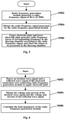
- FIG. 5 is a flow chart of a thawing method for a thawing device 100 according to an embodiment of the present invention.
- the thawing method for a thawing device 10 of the present invention may include the following steps:
- FIG. 6 is a flow chart of a method for obtaining the load impedance Z 2 of the radio frequency generation module 130 according to an embodiment of the present invention.
- the method for obtaining the load impedance Z 2 of the radio frequency generation module 130 may include the following steps:
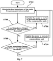
- FIG. 7 is a flow chart of a method for determining whether to enable the load compensation module 160 to work according to an embodiment of the present invention.
- the method for determining whether to enable the load compensation module 160 to work may include the following steps:
- FIG. 8 is a flow chart of a method for determining a thawing progress of an object to be processed according to an embodiment of the present invention.
- the method for determining the thawing progress of the object to be processed may include the following steps:
- FIG. 9 is a schematic structural view of a refrigerator 10 according to an embodiment of the present invention, where all outer doors of the refrigerator 10 are removed to show chamber structures in a refrigerator body 200 of the refrigerator 10.
- FIG. 10 is a schematic cross-sectional view of the refrigerator 10 as shown in FIG. 9 .
- the refrigerator 10 may generally include a refrigerator body 200 defining at least one containing space, compartment doors for respectively opening and closing an access port of each containing space, and a thawing device 100 disposed in one containing space.
- the refrigerator 10 includes three containing spaces, namely a refrigerating chamber 210, a temperature-variable chamber 220 and a freezing chamber 230, and also includes a refrigerating door 211, a temperature-variable door 221 and a freezing door 231 for opening and closing the refrigerating chamber 210, the temperature-variable chamber 220 and the freezing chamber 230 respectively.
- the thawing device 100 is disposed in the temperature-variable chamber 220.
- the refrigerating chamber 210 refers to a storage chamber having a storage temperature of 0 to +8°C for food materials
- the freezing chamber 230 refers to a storage chamber having a storage temperature of -20 to -15°C for food materials
- the temperature-variable chamber 220 refers to a storage chamber capable of changing a storage temperature in a wider range (for example, the adjusting range may be 4°C or above and the temperature may be adjusted to 0°C or above, or 0°C or below), and generally, the storage temperature may span refrigerating temperature, soft freezing temperature (generally -4 to 0°C) and freezing temperature, preferably -16 to +4°C.
- the refrigerator 10 may be an air-cooled refrigerator, and the temperature-variable chamber 220 may include an air duct cover plate.
- the air duct cover plate and a rear inner wall of the temperature-variable chamber 220 clamp to form a temperature-variable air duct, and the air duct cover plate is provided with a temperature-variable air inlet for providing the cooling capacity for the temperature-variable chamber 220.
- the device air inlet 215 of the thawing device 200 may be connected with the temperature-variable air inlet through a connecting pipe so as to facilitate refrigeration of the thawing chamber 114 of the thawing device 100.
- the projection of the device air inlet 115 of the thawing device 100 in a thickness direction of the rear plate of the cavity 110 may be in the temperature-variable air inlet so as to facilitate refrigeration of the thawing chamber 114 of the thawing device 100.
- a thawing switch 224 for controlling the start or stop of a thawing program may be disposed on any one of compartment doors.
- the radio frequency generation module 130 may be configured to: start to work when the thawing switch 224 is turned on, and stop working when the thawing switch 224 is turned off.
- a user can terminate the thawing program by turning off the thawing switch 224.
- a buzzer (not shown) may also be disposed on at least one compartment door and is configured to prompt the user that the object to be processed is thawed.
- the buzzer may be configured to: start to work when the detection module 150 determines that the object to be processed is thawed (the change rate of the dielectric coefficient of the object to be processed decreases to be less than or equal to the second preset threshold), and stop working when the object to be processed is taken out of the thawing chamber 114.
- a distance between the thawing device 100 and the inner walls of two transverse sides of the containing space provided with the thawing device 100 may be 2 to 3 mm, such as 2 mm, 2.5 mm or 3 mm, so that the gas in the thawing chamber can be discharged to the containing space.
- the thawing device 100 may be fixed in the containing space by interference fit or clamping with the inner walls of two vertical sides of the containing space.
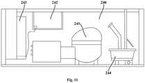
- FIG. 11 is a schematic structural view of a compressor room 240 in FIG. 10 .
- the refrigerator body 200 of the refrigerator 10 also defines the compressor room 240.
- the compressor room 240 may include a main control panel 243 for controlling operation of the refrigerator 10, a compressor 241, a condensed water collecting structure 244 and an external power wire (not shown) for supplying power for operation of the refrigerator 10, which are sequentially disposed.
- the refrigerator 10 may also include a power supply module 242 for supplying power for the radio frequency generation module 130.
- the power supply module 242 may be disposed in the compressor room 240 of the refrigerator 10 to facilitate heat dissipation and maintenance of the power supply module 242.
- the rear plate of the cavity 110 may be provided with a second wire passing port 116, so that the power supply module 242 is electrically connected with the radio frequency generation module 130 through the second wire passing port 116.
- the power supply module 242 may be fixed on an upper wall of the compressor room 240 to facilitate electrical connection between the radio frequency generation module 130 and the power supply module 242.
- the power supply module 242 may be an ACDC converter.
- the ACDC converter may be electrically connected with the main control panel 243 to supply power for the radio frequency generation module 130.
- the ACDC converter may be disposed between the main control panel 243 and the compressor 241 to make the electrical connection between the power supply module 242 and the main control panel 243 more convenient. It can be understood by those skilled in the art that it is easy to connect each component of the thawing device 100 with the control circuit of the refrigerator 10.
- FIG. 12 is a detailed flow chart of a thawing method for a refrigerator 10 according to an embodiment of the present invention.
- the thawing method for the refrigerator 10 may include the following steps:
- the thawing method further include the following steps after the S1204:
- a thawing working flow of a refrigerator 10 may include: when a user turns on the thawing switch 224, the power supply module 242 starts to supply power, the radio frequency generation module 130 generates a radio frequency signal of 40.68 MHz, and the detection module 150 and the load compensation module 160 start to work.
- the detection module 150 detects the incident wave signal and the reflected wave signal of the electrical connection wire connecting the radio frequency generation module 130 to the upper electrode plate, and calculates the load impedance Z 2 of the radio frequency generation module 130 and the change rate ⁇ / ⁇ t of the dielectric coefficient.
- the load compensation module 160 adjusts the impedance of the compensation unit through the motor so as to adjust the load impedance Z 2 of the radio frequency generation module 130, so that the difference between the load impedance Z 2 of the radio frequency generation module 130 and the output impedance Z 1 of the radio frequency generation module 130 is always greater than or equal to the first impedance threshold and less than or equal to the second preset threshold.
- the power supply module 242 stops supplying power, the radio frequency generation module 130, the detection module 150 and the load compensation module 160 stop working, and the buzzer starts to work.
- the buzzer stops working.
Landscapes
- Engineering & Computer Science (AREA)
- Life Sciences & Earth Sciences (AREA)
- Chemical & Material Sciences (AREA)
- Physics & Mathematics (AREA)
- Polymers & Plastics (AREA)
- Wood Science & Technology (AREA)
- Zoology (AREA)
- Food Science & Technology (AREA)
- Mechanical Engineering (AREA)
- Thermal Sciences (AREA)
- General Engineering & Computer Science (AREA)
- Combustion & Propulsion (AREA)
- Electromagnetism (AREA)
- Freezing, Cooling And Drying Of Foods (AREA)
- Constitution Of High-Frequency Heating (AREA)
- Electric Ovens (AREA)
Claims (8)
- Auftauverfahren für eine Auftauvorrichtung (100), wobei die Auftauvorrichtung umfasst: einen Hohlraum (110), der eine Auftaukammer definiert, die zum Einbringen eines zu verarbeitenden Objekts ausgestaltet ist und eine nach vorn weisende Öffnung aufweist, eine Vorrichtungstür (120), die an der nach vorn weisenden Öffnung der Auftaukammer angeordnet und dazu ausgestaltet ist, die Auftaukammer zu öffnen und zu verschließen, ein Hochfrequenzerzeugungsmodul (130) und eine obere Elektrodenplatte (140a) und eine untere Elektrodenplatte (140b), die horizontal entsprechend an einer oberen Wand und einer unteren Wand der Auftaukammer angeordnet und jeweils elektrisch mit dem Hochfrequenzerzeugungsmodul verbunden sind; wobei das Auftauverfahren Folgendes umfasst:Erzeugen - durch das Hochfrequenzerzeugungsmodul - eines Hochfrequenzsignals in einem Frequenzbereich von 40 bis 42 MHz;Erhalten des Hochfrequenzsignals; undErzeugen - durch die obere Elektrodenplatte und die untere Elektrodenplatte - von Hochfrequenzwellen mit einer entsprechenden Frequenz in der Auftaukammer gemäß dem Hochfrequenzsignal und Auftauen des zu verarbeitenden Objekts in der Auftaukammer;dadurch gekennzeichnet, dass
die Auftauvorrichtung ferner ein Erfassungsmodul (150) umfasst und das Erfassungsmodul dazu ausgestaltet ist, ein einfallendes Wellensignal und ein reflektiertes Wellensignal einer elektrischen Verbindungsleitung, die das Hochfrequenzerzeugungsmodul mit der oberen Elektrodenplatte verbindet, zu erfassen;
wobei das Auftauverfahren Folgendes umfasst:Erfassen des einfallenden Wellensignals und des reflektierten Wellensignals der elektrischen Verbindungsleitung;Erhalten einer Spannung und einer Stromstärke des einfallenden Wellensignals und einer Spannung und einer Stromstärke des reflektierten Wellensignals; undBerechnen einer Lastimpedanz des Hochfrequenzerzeugungsmoduls;wobei die Auftauvorrichtung ferner ein Lastausgleichsmodul (160) umfasst und das Lastausgleichsmodul eine Ausgleichseinheit, die mit dem zu verarbeitenden Objekt in Reihe geschaltet ist, und einen Motor, der dazu ausgestaltet ist, eine Impedanz der Ausgleichseinheit zu erhöhen oder zu vermindern, umfasst; und
wobei das Auftauverfahren Folgendes umfasst:Erhalten der Lastimpedanz des Hochfrequenzerzeugungsmoduls;Bestimmen, ob eine Differenz zwischen der Lastimpedanz des Hochfrequenzerzeugungsmoduls und einer Ausgangsimpedanz des Hochfrequenzerzeugungsmoduls größer als oder gleich eine(r) erste(n) Impedanzschwelle und kleiner als oder gleich eine(r) zweite(n) Impedanzschwelle ist oder nicht, wobei die erste Impedanzschwelle kleiner ist als die zweite Impedanzschwelle;wenn die Differenz zwischen der Lastimpedanz des Hochfrequenzerzeugungsmoduls und der Ausgangsimpedanz des Hochfrequenzerzeugungsmoduls kleiner als die erste Impedanzschwelle oder größer als die zweite Impedanzschwelle ist, Versetzen des Lastausgleichsmoduls in einen arbeitsfähigen Zustand; undwenn die Differenz zwischen der Lastimpedanz des Hochfrequenzerzeugungsmoduls und der Ausgangsimpedanz des Hochfrequenzerzeugungsmoduls größer als oder gleich die/der erste(n) Impedanzschwelle und kleiner als oder gleich die/der zweite(n) Impedanzschwelle ist, Versetzen des Lastausgleichsmoduls in einen nicht arbeitsfähigen Zustand. - Auftauverfahren für eine Auftauvorrichtung nach Anspruch 1, wobei das Hochfrequenzsignal eine konstante Frequenz aufweist, die in einem Bereich von 40,48 bis 40,68 MHz voreingestellt ist.
- Auftauverfahren für eine Auftauvorrichtung nach Anspruch 1, wobei der Schritt des Versetzens des Lastausgleichsmoduls in einen arbeitsfähigen Zustand, Folgendes umfasst:wenn die Differenz zwischen der Lastimpedanz des Hochfrequenzerzeugungsmoduls und der Ausgangsimpedanz des Hochfrequenzerzeugungsmoduls kleiner ist als die erste Impedanzschwelle, Erhöhen der Impedanz der Ausgleichseinheit; undwenn die Differenz zwischen der Lastimpedanz des Hochfrequenzerzeugungsmoduls und der Ausgangsimpedanz des Hochfrequenzerzeugungsmoduls größer ist als die zweite Impedanzschwelle, Vermindern der Impedanz der Ausgleichseinheit.
- Auftauverfahren für eine Auftauvorrichtung nach Anspruch 1, Folgendes umfassend:Erhalten der Lastimpedanz des Hochfrequenzerzeugungsmoduls;Berechnen einer Änderungsrate einer Dielektrizitätskonstante des zu verarbeitenden Objekts; undBestimmen eines Auftaufortschritts des zu verarbeitenden Objekts.
- Auftauverfahren für eine Auftauvorrichtung nach Anspruch 4, wobei der Schritt des Bestimmens des Auftaufortschritts des zu verarbeitenden Objekts Folgendes umfasst:Erhalten der Änderungsrate der Dielektrizitätskonstante des zu verarbeitenden Objekts;Bestimmen, ob die Änderungsrate der Dielektrizitätskonstante des zu verarbeitenden Objekts größer als oder gleich eine(r) erste(n) Ratenschwelle ist oder nicht; undwenn ja, Vermindern einer Arbeitsleistung des Hochfrequenzerzeugungsmoduls um 30 % bis 40 %.
- Auftauverfahren für eine Auftauvorrichtung nach Anspruch 4, wobei der Schritt des Bestimmens des Auftaufortschritts des zu verarbeitenden Objekts Folgendes umfasst:Erhalten der Änderungsrate der Dielektrizitätskonstante des zu verarbeitenden Objekts;Bestimmen, ob die Änderungsrate der Dielektrizitätskonstante des zu verarbeitenden Objekts abnimmt, so dass sie kleiner als oder gleich eine(r) zweite(n) Ratenschwelle ist, oder nicht; undwenn die Änderungsrate abnimmt, so dass sie kleiner als oder gleich die/der zweite(n) Ratenschwelle ist, Versetzen des Hochfrequenzerzeugungsmoduls in einen zur Einstellung der Arbeit fähigen Zustand.
- Auftauverfahren für einen Kühlschrank (9),
wobei der Kühlschrank einen Kühlschrankkörper (200), der wenigstens einen Aufnahmeraum definiert, eine Fachtür (221) zum separaten Öffnen und Verschließen des Aufnahmeraums und eine Auftauvorrichtung (100), die in einem der Aufnahmeräume angeordnet ist, umfasst; das Auftauverfahren die Auftauverfahren für eine Auftauvorrichtung nach einem der Ansprüche 1 bis 6 umfasst. - Auftauverfahren für einen Kühlschrank nach Anspruch 7, wobei der Kühlschrank ferner ein Stromversorgungsmodul (242) zum Zuführen von Strom zu der Auftauvorrichtung umfasst und an einer der Fachtüren ein Auftauschalter (224) zum Steuern des Startens und Beendens eines Auftauprogramms angeordnet ist; wobei das Auftauverfahren für einen Kühlschrank Folgendes umfasst:wenn der Auftauschalter eingeschaltet wird, Versetzen des Stromversorgungsmoduls in einen zur Aufnahme der Arbeit fähigen Zustand; undwenn der Auftauschalter ausgeschaltet wird, Versetzen des Stromversorgungsmoduls in einen zur Einstellung der Arbeit fähigen Zustand.
Priority Applications (1)
| Application Number | Priority Date | Filing Date | Title |
|---|---|---|---|
| PL18814417T PL3617620T3 (pl) | 2017-06-06 | 2018-06-05 | Sposób rozmrażania dla urządzenia do rozmrażania |
Applications Claiming Priority (2)
| Application Number | Priority Date | Filing Date | Title |
|---|---|---|---|
| CN201710418935.5A CN108991338B (zh) | 2017-06-06 | 2017-06-06 | 用于解冻装置的解冻方法 |
| PCT/CN2018/089860 WO2018223938A1 (zh) | 2017-06-06 | 2018-06-05 | 用于解冻装置的解冻方法 |
Publications (3)
| Publication Number | Publication Date |
|---|---|
| EP3617620A1 EP3617620A1 (de) | 2020-03-04 |
| EP3617620A4 EP3617620A4 (de) | 2020-06-03 |
| EP3617620B1 true EP3617620B1 (de) | 2022-01-26 |
Family
ID=64566422
Family Applications (1)
| Application Number | Title | Priority Date | Filing Date |
|---|---|---|---|
| EP18814417.4A Active EP3617620B1 (de) | 2017-06-06 | 2018-06-05 | Abtauverfahren für abtauvorrichtung |
Country Status (7)
| Country | Link |
|---|---|
| US (1) | US11473829B2 (de) |
| EP (1) | EP3617620B1 (de) |
| CN (1) | CN108991338B (de) |
| AU (1) | AU2018280465B2 (de) |
| ES (1) | ES2910507T3 (de) |
| PL (1) | PL3617620T3 (de) |
| WO (1) | WO2018223938A1 (de) |
Families Citing this family (5)
| Publication number | Priority date | Publication date | Assignee | Title |
|---|---|---|---|---|
| CN109000407B (zh) * | 2017-06-06 | 2020-05-26 | 青岛海尔股份有限公司 | 冰箱 |
| CN111918432B (zh) * | 2019-05-07 | 2023-02-17 | 青岛海尔智能技术研发有限公司 | 射频加热设备 |
| CN114521033A (zh) * | 2020-11-20 | 2022-05-20 | 青岛海尔特种电冰箱有限公司 | 用于加热装置的控制方法及加热装置 |
| CN112577257A (zh) * | 2020-12-23 | 2021-03-30 | 珠海格力电器股份有限公司 | 解冻装置控制方法、控制设备及冰箱 |
| CN115767812B (zh) * | 2022-11-09 | 2026-01-27 | 中华全国供销合作总社济南果品研究所 | 一种隧道式射频解冻装置及其应用 |
Citations (1)
| Publication number | Priority date | Publication date | Assignee | Title |
|---|---|---|---|---|
| DE3818491C2 (de) * | 1988-05-31 | 1990-03-08 | Bosch-Siemens Hausgeraete Gmbh, 8000 Muenchen, De |
Family Cites Families (11)
| Publication number | Priority date | Publication date | Assignee | Title |
|---|---|---|---|---|
| JPS53104463A (en) * | 1977-02-23 | 1978-09-11 | Hitachi Ltd | Cold store |
| US6657173B2 (en) * | 1998-04-21 | 2003-12-02 | State Board Of Higher Education On Behalf Of Oregon State University | Variable frequency automated capacitive radio frequency (RF) dielectric heating system |
| KR101284592B1 (ko) * | 2006-02-15 | 2013-07-17 | 엘지전자 주식회사 | 냉장고 |
| CN105325055A (zh) * | 2013-06-28 | 2016-02-10 | 皇家飞利浦有限公司 | 用于处理冷冻食物的方法和设备 |
| US20160192667A1 (en) * | 2013-07-29 | 2016-07-07 | Tohoku University | Method of thawing frozen food |
| CN203446472U (zh) * | 2013-09-09 | 2014-02-26 | 浙江大洋水产有限公司 | 一种射频鱿鱼解冻生产线 |
| CN105940266B (zh) * | 2014-12-17 | 2017-10-20 | 皇家飞利浦有限公司 | 用于食物原料的加热的控制方法和设备 |
| US11284742B2 (en) * | 2015-09-01 | 2022-03-29 | Illinois Tool Works, Inc. | Multi-functional RF capacitive heating food preparation device |
| EP3280225B1 (de) * | 2016-08-05 | 2020-10-07 | NXP USA, Inc. | Abtauvorrichtung mit konzentriertem induktivem anpassungsnetzwerk und verfahren zum betrieb davon |
| CN106288626A (zh) * | 2016-08-29 | 2017-01-04 | 合肥华凌股份有限公司 | 一种解冻装置、冰箱及其解冻控制方法 |
| CN207095131U (zh) * | 2017-06-06 | 2018-03-13 | 青岛海尔股份有限公司 | 冰箱 |
-
2017
- 2017-06-06 CN CN201710418935.5A patent/CN108991338B/zh active Active
-
2018
- 2018-06-05 ES ES18814417T patent/ES2910507T3/es active Active
- 2018-06-05 AU AU2018280465A patent/AU2018280465B2/en active Active
- 2018-06-05 EP EP18814417.4A patent/EP3617620B1/de active Active
- 2018-06-05 PL PL18814417T patent/PL3617620T3/pl unknown
- 2018-06-05 WO PCT/CN2018/089860 patent/WO2018223938A1/zh not_active Ceased
-
2019
- 2019-12-06 US US16/706,147 patent/US11473829B2/en active Active
Patent Citations (1)
| Publication number | Priority date | Publication date | Assignee | Title |
|---|---|---|---|---|
| DE3818491C2 (de) * | 1988-05-31 | 1990-03-08 | Bosch-Siemens Hausgeraete Gmbh, 8000 Muenchen, De |
Also Published As
| Publication number | Publication date |
|---|---|
| CN108991338A (zh) | 2018-12-14 |
| US11473829B2 (en) | 2022-10-18 |
| AU2018280465A1 (en) | 2019-12-12 |
| WO2018223938A1 (zh) | 2018-12-13 |
| CN108991338B (zh) | 2021-11-26 |
| PL3617620T3 (pl) | 2022-06-13 |
| EP3617620A1 (de) | 2020-03-04 |
| EP3617620A4 (de) | 2020-06-03 |
| US20200116417A1 (en) | 2020-04-16 |
| ES2910507T3 (es) | 2022-05-12 |
| AU2018280465B2 (en) | 2021-04-29 |
Similar Documents
| Publication | Publication Date | Title |
|---|---|---|
| EP3617628B1 (de) | Auftauverfahren für auftauvorrichtung | |
| EP3617619B1 (de) | Kühlschrank | |
| EP3617618B1 (de) | Kühlschrank | |
| EP3617620B1 (de) | Abtauverfahren für abtauvorrichtung | |
| CN207095130U (zh) | 冰箱 | |
| CN109000397B (zh) | 用于解冻装置的解冻方法 | |
| CN109000419B (zh) | 解冻装置及具有该解冻装置的冰箱 | |
| CN207095160U (zh) | 解冻装置及具有该解冻装置的冰箱 | |
| CN207081264U (zh) | 冰箱 | |
| CN207095131U (zh) | 冰箱 | |
| CN109000418B (zh) | 解冻装置及具有该解冻装置的冰箱 | |
| CN109000401B (zh) | 冰箱 | |
| CN109000417B (zh) | 解冻装置及具有该解冻装置的冰箱 | |
| WO2018223947A1 (zh) | 冰箱 | |
| CN109000408B (zh) | 冰箱 | |
| CN109000406B (zh) | 冰箱 | |
| CN109000420B (zh) | 解冻装置及具有该解冻装置的冰箱 | |
| CN109000404B (zh) | 冰箱 | |
| CN109000409B (zh) | 解冻装置及具有该解冻装置的冰箱 | |
| CN109000400B (zh) | 对开门冰箱 | |
| CN109000410B (zh) | 冰箱 | |
| CN109000411B (zh) | 冰箱 |
Legal Events
| Date | Code | Title | Description |
|---|---|---|---|
| STAA | Information on the status of an ep patent application or granted ep patent |
Free format text: STATUS: THE INTERNATIONAL PUBLICATION HAS BEEN MADE |
|
| PUAI | Public reference made under article 153(3) epc to a published international application that has entered the european phase |
Free format text: ORIGINAL CODE: 0009012 |
|
| STAA | Information on the status of an ep patent application or granted ep patent |
Free format text: STATUS: REQUEST FOR EXAMINATION WAS MADE |
|
| 17P | Request for examination filed |
Effective date: 20191126 |
|
| AK | Designated contracting states |
Kind code of ref document: A1 Designated state(s): AL AT BE BG CH CY CZ DE DK EE ES FI FR GB GR HR HU IE IS IT LI LT LU LV MC MK MT NL NO PL PT RO RS SE SI SK SM TR |
|
| AX | Request for extension of the european patent |
Extension state: BA ME |
|
| REG | Reference to a national code |
Ref country code: DE Ref legal event code: R079 Ref document number: 602018030183 Country of ref document: DE Free format text: PREVIOUS MAIN CLASS: F25D0011020000 Ipc: H05B0006620000 |
|
| A4 | Supplementary search report drawn up and despatched |
Effective date: 20200504 |
|
| RIC1 | Information provided on ipc code assigned before grant |
Ipc: H05B 6/62 20060101AFI20200427BHEP Ipc: F25D 11/02 20060101ALI20200427BHEP Ipc: A23L 3/365 20060101ALI20200427BHEP |
|
| STAA | Information on the status of an ep patent application or granted ep patent |
Free format text: STATUS: EXAMINATION IS IN PROGRESS |
|
| 17Q | First examination report despatched |
Effective date: 20200810 |
|
| DAV | Request for validation of the european patent (deleted) | ||
| DAX | Request for extension of the european patent (deleted) | ||
| GRAP | Despatch of communication of intention to grant a patent |
Free format text: ORIGINAL CODE: EPIDOSNIGR1 |
|
| STAA | Information on the status of an ep patent application or granted ep patent |
Free format text: STATUS: GRANT OF PATENT IS INTENDED |
|
| INTG | Intention to grant announced |
Effective date: 20210923 |
|
| GRAS | Grant fee paid |
Free format text: ORIGINAL CODE: EPIDOSNIGR3 |
|
| GRAA | (expected) grant |
Free format text: ORIGINAL CODE: 0009210 |
|
| STAA | Information on the status of an ep patent application or granted ep patent |
Free format text: STATUS: THE PATENT HAS BEEN GRANTED |
|
| AK | Designated contracting states |
Kind code of ref document: B1 Designated state(s): AL AT BE BG CH CY CZ DE DK EE ES FI FR GB GR HR HU IE IS IT LI LT LU LV MC MK MT NL NO PL PT RO RS SE SI SK SM TR |
|
| REG | Reference to a national code |
Ref country code: GB Ref legal event code: FG4D |
|
| REG | Reference to a national code |
Ref country code: CH Ref legal event code: EP |
|
| REG | Reference to a national code |
Ref country code: AT Ref legal event code: REF Ref document number: 1466312 Country of ref document: AT Kind code of ref document: T Effective date: 20220215 |
|
| REG | Reference to a national code |
Ref country code: IE Ref legal event code: FG4D |
|
| REG | Reference to a national code |
Ref country code: DE Ref legal event code: R096 Ref document number: 602018030183 Country of ref document: DE |
|
| REG | Reference to a national code |
Ref country code: ES Ref legal event code: FG2A Ref document number: 2910507 Country of ref document: ES Kind code of ref document: T3 Effective date: 20220512 |
|
| REG | Reference to a national code |
Ref country code: LT Ref legal event code: MG9D |
|
| REG | Reference to a national code |
Ref country code: NL Ref legal event code: MP Effective date: 20220126 |
|
| REG | Reference to a national code |
Ref country code: AT Ref legal event code: MK05 Ref document number: 1466312 Country of ref document: AT Kind code of ref document: T Effective date: 20220126 |
|
| PG25 | Lapsed in a contracting state [announced via postgrant information from national office to epo] |
Ref country code: NL Free format text: LAPSE BECAUSE OF FAILURE TO SUBMIT A TRANSLATION OF THE DESCRIPTION OR TO PAY THE FEE WITHIN THE PRESCRIBED TIME-LIMIT Effective date: 20220126 |
|
| PG25 | Lapsed in a contracting state [announced via postgrant information from national office to epo] |
Ref country code: SE Free format text: LAPSE BECAUSE OF FAILURE TO SUBMIT A TRANSLATION OF THE DESCRIPTION OR TO PAY THE FEE WITHIN THE PRESCRIBED TIME-LIMIT Effective date: 20220126 Ref country code: RS Free format text: LAPSE BECAUSE OF FAILURE TO SUBMIT A TRANSLATION OF THE DESCRIPTION OR TO PAY THE FEE WITHIN THE PRESCRIBED TIME-LIMIT Effective date: 20220126 Ref country code: PT Free format text: LAPSE BECAUSE OF FAILURE TO SUBMIT A TRANSLATION OF THE DESCRIPTION OR TO PAY THE FEE WITHIN THE PRESCRIBED TIME-LIMIT Effective date: 20220526 Ref country code: NO Free format text: LAPSE BECAUSE OF FAILURE TO SUBMIT A TRANSLATION OF THE DESCRIPTION OR TO PAY THE FEE WITHIN THE PRESCRIBED TIME-LIMIT Effective date: 20220426 Ref country code: LT Free format text: LAPSE BECAUSE OF FAILURE TO SUBMIT A TRANSLATION OF THE DESCRIPTION OR TO PAY THE FEE WITHIN THE PRESCRIBED TIME-LIMIT Effective date: 20220126 Ref country code: HR Free format text: LAPSE BECAUSE OF FAILURE TO SUBMIT A TRANSLATION OF THE DESCRIPTION OR TO PAY THE FEE WITHIN THE PRESCRIBED TIME-LIMIT Effective date: 20220126 Ref country code: BG Free format text: LAPSE BECAUSE OF FAILURE TO SUBMIT A TRANSLATION OF THE DESCRIPTION OR TO PAY THE FEE WITHIN THE PRESCRIBED TIME-LIMIT Effective date: 20220426 |
|
| PG25 | Lapsed in a contracting state [announced via postgrant information from national office to epo] |
Ref country code: LV Free format text: LAPSE BECAUSE OF FAILURE TO SUBMIT A TRANSLATION OF THE DESCRIPTION OR TO PAY THE FEE WITHIN THE PRESCRIBED TIME-LIMIT Effective date: 20220126 Ref country code: GR Free format text: LAPSE BECAUSE OF FAILURE TO SUBMIT A TRANSLATION OF THE DESCRIPTION OR TO PAY THE FEE WITHIN THE PRESCRIBED TIME-LIMIT Effective date: 20220427 Ref country code: FI Free format text: LAPSE BECAUSE OF FAILURE TO SUBMIT A TRANSLATION OF THE DESCRIPTION OR TO PAY THE FEE WITHIN THE PRESCRIBED TIME-LIMIT Effective date: 20220126 Ref country code: AT Free format text: LAPSE BECAUSE OF FAILURE TO SUBMIT A TRANSLATION OF THE DESCRIPTION OR TO PAY THE FEE WITHIN THE PRESCRIBED TIME-LIMIT Effective date: 20220126 |
|
| PG25 | Lapsed in a contracting state [announced via postgrant information from national office to epo] |
Ref country code: IS Free format text: LAPSE BECAUSE OF FAILURE TO SUBMIT A TRANSLATION OF THE DESCRIPTION OR TO PAY THE FEE WITHIN THE PRESCRIBED TIME-LIMIT Effective date: 20220526 |
|
| REG | Reference to a national code |
Ref country code: DE Ref legal event code: R097 Ref document number: 602018030183 Country of ref document: DE |
|
| PG25 | Lapsed in a contracting state [announced via postgrant information from national office to epo] |
Ref country code: SM Free format text: LAPSE BECAUSE OF FAILURE TO SUBMIT A TRANSLATION OF THE DESCRIPTION OR TO PAY THE FEE WITHIN THE PRESCRIBED TIME-LIMIT Effective date: 20220126 Ref country code: SK Free format text: LAPSE BECAUSE OF FAILURE TO SUBMIT A TRANSLATION OF THE DESCRIPTION OR TO PAY THE FEE WITHIN THE PRESCRIBED TIME-LIMIT Effective date: 20220126 Ref country code: RO Free format text: LAPSE BECAUSE OF FAILURE TO SUBMIT A TRANSLATION OF THE DESCRIPTION OR TO PAY THE FEE WITHIN THE PRESCRIBED TIME-LIMIT Effective date: 20220126 Ref country code: EE Free format text: LAPSE BECAUSE OF FAILURE TO SUBMIT A TRANSLATION OF THE DESCRIPTION OR TO PAY THE FEE WITHIN THE PRESCRIBED TIME-LIMIT Effective date: 20220126 Ref country code: DK Free format text: LAPSE BECAUSE OF FAILURE TO SUBMIT A TRANSLATION OF THE DESCRIPTION OR TO PAY THE FEE WITHIN THE PRESCRIBED TIME-LIMIT Effective date: 20220126 Ref country code: CZ Free format text: LAPSE BECAUSE OF FAILURE TO SUBMIT A TRANSLATION OF THE DESCRIPTION OR TO PAY THE FEE WITHIN THE PRESCRIBED TIME-LIMIT Effective date: 20220126 |
|
| PG25 | Lapsed in a contracting state [announced via postgrant information from national office to epo] |
Ref country code: AL Free format text: LAPSE BECAUSE OF FAILURE TO SUBMIT A TRANSLATION OF THE DESCRIPTION OR TO PAY THE FEE WITHIN THE PRESCRIBED TIME-LIMIT Effective date: 20220126 |
|
| PLBE | No opposition filed within time limit |
Free format text: ORIGINAL CODE: 0009261 |
|
| STAA | Information on the status of an ep patent application or granted ep patent |
Free format text: STATUS: NO OPPOSITION FILED WITHIN TIME LIMIT |
|
| 26N | No opposition filed |
Effective date: 20221027 |
|
| PG25 | Lapsed in a contracting state [announced via postgrant information from national office to epo] |
Ref country code: MC Free format text: LAPSE BECAUSE OF FAILURE TO SUBMIT A TRANSLATION OF THE DESCRIPTION OR TO PAY THE FEE WITHIN THE PRESCRIBED TIME-LIMIT Effective date: 20220126 |
|
| REG | Reference to a national code |
Ref country code: CH Ref legal event code: PL |
|
| REG | Reference to a national code |
Ref country code: BE Ref legal event code: MM Effective date: 20220630 |
|
| PG25 | Lapsed in a contracting state [announced via postgrant information from national office to epo] |
Ref country code: SI Free format text: LAPSE BECAUSE OF FAILURE TO SUBMIT A TRANSLATION OF THE DESCRIPTION OR TO PAY THE FEE WITHIN THE PRESCRIBED TIME-LIMIT Effective date: 20220126 |
|
| PG25 | Lapsed in a contracting state [announced via postgrant information from national office to epo] |
Ref country code: IE Free format text: LAPSE BECAUSE OF NON-PAYMENT OF DUE FEES Effective date: 20220605 Ref country code: CH Free format text: LAPSE BECAUSE OF NON-PAYMENT OF DUE FEES Effective date: 20220630 Ref country code: LU Free format text: LAPSE BECAUSE OF NON-PAYMENT OF DUE FEES Effective date: 20220605 Ref country code: LI Free format text: LAPSE BECAUSE OF NON-PAYMENT OF DUE FEES Effective date: 20220630 |
|
| PG25 | Lapsed in a contracting state [announced via postgrant information from national office to epo] |
Ref country code: BE Free format text: LAPSE BECAUSE OF NON-PAYMENT OF DUE FEES Effective date: 20220630 |
|
| PG25 | Lapsed in a contracting state [announced via postgrant information from national office to epo] |
Ref country code: MK Free format text: LAPSE BECAUSE OF FAILURE TO SUBMIT A TRANSLATION OF THE DESCRIPTION OR TO PAY THE FEE WITHIN THE PRESCRIBED TIME-LIMIT Effective date: 20220126 Ref country code: CY Free format text: LAPSE BECAUSE OF FAILURE TO SUBMIT A TRANSLATION OF THE DESCRIPTION OR TO PAY THE FEE WITHIN THE PRESCRIBED TIME-LIMIT Effective date: 20220126 |
|
| PG25 | Lapsed in a contracting state [announced via postgrant information from national office to epo] |
Ref country code: HU Free format text: LAPSE BECAUSE OF FAILURE TO SUBMIT A TRANSLATION OF THE DESCRIPTION OR TO PAY THE FEE WITHIN THE PRESCRIBED TIME-LIMIT; INVALID AB INITIO Effective date: 20180605 |
|
| PG25 | Lapsed in a contracting state [announced via postgrant information from national office to epo] |
Ref country code: TR Free format text: LAPSE BECAUSE OF FAILURE TO SUBMIT A TRANSLATION OF THE DESCRIPTION OR TO PAY THE FEE WITHIN THE PRESCRIBED TIME-LIMIT Effective date: 20220126 |
|
| PG25 | Lapsed in a contracting state [announced via postgrant information from national office to epo] |
Ref country code: MT Free format text: LAPSE BECAUSE OF FAILURE TO SUBMIT A TRANSLATION OF THE DESCRIPTION OR TO PAY THE FEE WITHIN THE PRESCRIBED TIME-LIMIT Effective date: 20220126 |
|
| PGFP | Annual fee paid to national office [announced via postgrant information from national office to epo] |
Ref country code: DE Payment date: 20250617 Year of fee payment: 8 Ref country code: PL Payment date: 20250526 Year of fee payment: 8 |
|
| PGFP | Annual fee paid to national office [announced via postgrant information from national office to epo] |
Ref country code: GB Payment date: 20250625 Year of fee payment: 8 |
|
| PGFP | Annual fee paid to national office [announced via postgrant information from national office to epo] |
Ref country code: FR Payment date: 20250630 Year of fee payment: 8 |
|
| PGFP | Annual fee paid to national office [announced via postgrant information from national office to epo] |
Ref country code: ES Payment date: 20250710 Year of fee payment: 8 |
|
| PGFP | Annual fee paid to national office [announced via postgrant information from national office to epo] |
Ref country code: IT Payment date: 20250606 Year of fee payment: 8 |