EP3617671B1 - Dispositif de pesage par combinaison - Google Patents
Dispositif de pesage par combinaison Download PDFInfo
- Publication number
- EP3617671B1 EP3617671B1 EP19177191.4A EP19177191A EP3617671B1 EP 3617671 B1 EP3617671 B1 EP 3617671B1 EP 19177191 A EP19177191 A EP 19177191A EP 3617671 B1 EP3617671 B1 EP 3617671B1
- Authority
- EP
- European Patent Office
- Prior art keywords
- hoppers
- weighing
- article
- combination
- control unit
- Prior art date
- Legal status (The legal status is an assumption and is not a legal conclusion. Google has not performed a legal analysis and makes no representation as to the accuracy of the status listed.)
- Active
Links
Images



Classifications
-
- G—PHYSICS
- G01—MEASURING; TESTING
- G01G—WEIGHING
- G01G13/00—Weighing apparatus with automatic feed or discharge for weighing-out batches of material
- G01G13/24—Weighing mechanism control arrangements for automatic feed or discharge
- G01G13/28—Weighing mechanism control arrangements for automatic feed or discharge involving variation of an electrical variable which is used to control loading or discharge of the receptacle
- G01G13/29—Weighing mechanism control arrangements for automatic feed or discharge involving variation of an electrical variable which is used to control loading or discharge of the receptacle involving digital counting
-
- G—PHYSICS
- G01—MEASURING; TESTING
- G01G—WEIGHING
- G01G13/00—Weighing apparatus with automatic feed or discharge for weighing-out batches of material
- G01G13/003—Details; specially adapted accessories
-
- G—PHYSICS
- G01—MEASURING; TESTING
- G01G—WEIGHING
- G01G19/00—Weighing apparatus or methods adapted for special purposes not provided for in the preceding groups
- G01G19/387—Weighing apparatus or methods adapted for special purposes not provided for in the preceding groups for combinatorial weighing, i.e. selecting a combination of articles whose total weight or number is closest to a desired value
-
- G—PHYSICS
- G01—MEASURING; TESTING
- G01G—WEIGHING
- G01G19/00—Weighing apparatus or methods adapted for special purposes not provided for in the preceding groups
- G01G19/387—Weighing apparatus or methods adapted for special purposes not provided for in the preceding groups for combinatorial weighing, i.e. selecting a combination of articles whose total weight or number is closest to a desired value
- G01G19/393—Weighing apparatus or methods adapted for special purposes not provided for in the preceding groups for combinatorial weighing, i.e. selecting a combination of articles whose total weight or number is closest to a desired value using two or more weighing units
Definitions
- One aspect of the present invention relates to a combination weighing device.
- the combination weighing device of the above technology needs to be stopped to eliminate the abnormal condition. In this case, an operation rate of the combination weighing device may drop.
- one aspect of the present invention is to provide a combination weighing device capable of reducing an operation rate drop of the device.
- a combination weighing device comprises: a conveyance unit configured to convey an article; a plurality of first hoppers each configured to receive the article conveyed by the conveyance unit, temporarily hold the received article, and then discharge the article downstream; a plurality of second hoppers detachably provided on a downstream side of the plurality of first hoppers, and each configured to receive the article discharged from corresponding one of the plurality of first hoppers, temporarily hold the received article, and then discharge the article downstream; a weighing unit configured to weigh the article held in each of the plurality of second hoppers, and obtain a weighing value corresponding to mass of the article; and a control unit configured to perform combination calculation to select such a combination of weighing values a total value of which becomes a target weighing value, and discharge the article from the second hopper corresponding to the combination.
- the control unit performs the combination calculation based on the weighing value corresponding to the mass of the article held in each of the plurality of second hoppers. In a state in which a part of the second hoppers has been removed from the plurality of second hoppers, the control unit continues the combination calculation based on the weighing value corresponding to the mass of the article held in each of the plurality of second hoppers other than the part of the second hoppers.
- the control unit performs combination calculation based on a weighing value corresponding to mass of the article held in each of the plurality of second hoppers, and continues combination calculation based on a weighing value corresponding to mass of the article held in each of the second hoppers other than a part of the second hoppers in a state in which the part of the plurality of second hoppers has been removed. Accordingly, even in a state in which a part of the second hoppers has been removed to eliminate an abnormal condition currently caused, for example, combination calculation can be continued based on the second hoppers other than the part of the second hoppers without stopping the combination weighing device. Accordingly, an operation rate drop is avoidable.
- the weighing unit may perform zero point correction of the weighing value obtained by the weighing unit and corresponding to the mass of the article held in the part of the second hoppers when the part of the second hoppers after removal is attached.
- execution of zero point correction of the weighing values of the part of the second hoppers (hereinafter also simply referred to as "zero point correction"), and reduction of a zero point error of the weighing unit are achievable without stopping the combination weighing device after the part of the second hoppers are attached.
- the control unit may continue the combination calculation based on the weighing value corresponding to the mass of the article held in each of the plurality of second hoppers including a part of the second hoppers when the weighing unit performs zero point correction.
- the part of the second hoppers can be again added to combination calculation without stopping the combination weighing device after attachment of the part of the second hoppers and zero point correction by the weighing unit.
- the control unit may start combination calculation based on a weighing value corresponding to mass of the article held in each of the second hoppers other than the part of the second hoppers. In this manner, combination calculation based on the weighing value corresponding to the mass of the article held in each of the second hoppers other than the part of the second hoppers can be started in response to the removal of the part of the second hoppers.
- the control unit may start combination calculation based on a weighing value corresponding to mass of the article held in each of the second hoppers other than the part of the second hoppers. In this manner, combination calculation based on the weighing value corresponding to the mass of the article held in each of the second hoppers other than the part of the second hoppers can be started in response to the error of the part of the second hoppers.
- the control unit may start combination calculation based on a weighing value corresponding to mass of the article held in each of the second hoppers other than the part of the second hoppers. In this manner, combination calculation based on the weighing value corresponding to the mass of the article held in each of the second hoppers other than the part of the second hoppers can be started in response to input of the operation for removing the part of the second hoppers from combination calculation.
- control unit of the combination weighing device of one aspect of the present invention may stop a discharging operation of the first hopper on the upstream side of the part of the second hoppers, and a conveying operation of the conveyance unit on the upstream side of the part of the second hoppers. In this manner, continuous supply of the articles to the attachment positions of the articles even after removal of the part of the second hoppers is avoidable.
- the combination weighing device of one aspect of the present invention may further comprise a notification unit configured to give notification about the error of the part of the second hoppers included in the plurality of second hoppers.
- a notification unit configured to give notification about the error of the part of the second hoppers included in the plurality of second hoppers.
- an error of a part of the second hoppers included in the plurality of second hoppers can be easily checked. Accordingly, the part of the second hoppers can be easily removed from the plurality of second hoppers, for example.
- each of the plurality of first hoppers may be detachably provided on a downstream side of the conveyance unit.
- the control unit may continue the combination calculation based on the weighing value corresponding to the mass of the article held in each of the second hoppers other than the second hopper on the downstream side of the part of the first hoppers.
- combination calculation can continue even in the state in which the part of the first hoppers has been removed from the plurality of first hoppers. Accordingly, an operation rate drop of the combination weighing device is avoidable.
- the combination weighing device of one aspect of the present invention may further comprise a plurality of third hoppers detachably provided on a downstream side of the plurality of second hoppers, and each configured to receive the article discharged from corresponding one of the plurality of second hoppers, temporarily hold the received article, and then discharge the article downstream.
- the control unit may continue the combination calculation based on the weighing value corresponding to the mass of the article held in each of the second hoppers other than the second hopper on an upstream side of the part of the third hoppers. In this case, combination calculation can continue even in the state in which the part of the third hoppers has been removed from the plurality of third hoppers. Accordingly, an operation rate drop of the combination weighing device is avoidable.
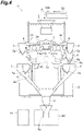
- a combination weighing device 1 includes a charge chute 2, a dispersion feeder 3, a plurality of radial feeders (conveyance unit) 4, a plurality of pool hoppers (first hoppers) 5, a plurality of weighing hoppers (second hoppers) 6, a plurality of booster hoppers 7 (third hoppers), a collection chute 8, a timing hopper 9, a weighing unit 11, a frame 12, a case 13, a notification unit 14, and a control unit 20.
- the combination weighing device 1 weighs an article A (article having variations in single mass, such as agricultural article, marine article, and processed food) supplied by a conveyor 50 to adjust a weight of the article A to a target weighing value, and supplies the article A to a bag forming and packaging machine 60.
- the bag forming and packaging machine 60 packs the article A supplied from the combination weighing device 1 while forming a film into a bag having a predetermined volume.
- the charge chute 2 is disposed below a conveyance end 50a of the conveyor 50.
- the charge chute 2 receives the article A dropped from the conveyance end 50a of the conveyor 50, and discharges the article A downstream.
- the charge chute 2 is directly or indirectly supported by the case 13 supported on the frame 12.
- the dispersion feeder 3 is disposed below the charge chute 2.
- the dispersion feeder 3 has a conveyance surface 3a which has a conical shape diverging downward.
- the dispersion feeder 3 conveys the articles A discharged from the charge chute 2 to a top portion of the conveyance surface 3a such that the articles A uniformly shift toward an outer edge of the conveyance surface 3a by vibrating the conveyance surface 3a.
- the dispersion feeder 3 is directly or indirectly supported by the case 13.
- the plurality of radial feeders 4 are disposed radially along the outer edge of the conveyance surface 3a of the dispersion feeder 3. Each of the radial feeders 4 has a trough 4a extending outward from below the outer edge of the conveyance surface 3a. Each of the radial feeders 4 conveys the article A discharged from the outer edge of the conveyance surface 3a toward a tip of the trough 4a by vibrating the trough 4a.
- the plurality of radial feeders 4 are directly or indirectly supported by the case 13.
- Each of the plurality of pool hoppers 5 is detachably provided on the downstream side of the corresponding radial feeder 4. Specifically, each of the pool hoppers 5 is disposed below the tip of the trough 4a of the corresponding radial feeder 4, and is supported directly or indirectly by the case 13. Each of the pool hoppers 5 of the present embodiment is detachably attached to the case 13. Attachment and detachment of the pool hoppers 5 is achievable by a known ordinary mechanism, for example.
- Each of the pool hoppers 5 has a gate 5a openable and closable for the bottom of the pool hopper 5. Each of the pool hoppers 5 closes the gate 5a to receive the article A conveyed by the corresponding radial feeder 4. Each of the pool hoppers 5 also temporarily holds the received article A, and then opens the gate 5a to discharge the article A downstream.
- Each of the plurality of weighing hoppers 6 is detachably provided on the downstream side of the corresponding pool hopper 5. Specifically, each of the weighing hoppers 6 is disposed below the gate 5a of the corresponding pool hopper 5, and is supported directly or indirectly by the case 13. Each of the weighing hoppers 6 of the present embodiment is detachably attached to the case 13. Each of the weighing hoppers 6 herein is detachably attached to a bracket or the like supported by a load cell 11a described below. Attachment and detachment of the weighing hoppers 6 is achievable by a known ordinary mechanism, for example. Each of the weighing hoppers 6 has a gate 6a and a gate 6b openable and closable for the bottom of the weighing hopper 6.
- Each of the weighing hoppers 6 closes the gates 6a and 6b to receive the article A discharged from the corresponding pool hopper 5. Each of the weighing hoppers 6 also temporarily holds the received article A, and then opens the gate 6a or the gate 6b to discharge the article A downstream.
- Each of the plurality of booster hoppers 7 is detachably provided on the downstream side of the corresponding weighing hopper 6. Specifically, each of the booster hoppers 7 is disposed below the gate 6a of the corresponding weighing hopper 6, and is supported directly or indirectly by the frame 12. Each of the booster hoppers 7 of the present embodiment is detachably attached to the frame 12. Attachment and detachment of the booster hoppers 7 is achievable by a known ordinary mechanism, for example.
- Each of the booster hoppers 7 has a gate 7a openable and closable for the bottom of the booster hopper 7. Each of the booster hoppers 7 closes the gate 7a to receive the article A discharged from the gate 6a side of the corresponding weighing hopper 6. Each of the booster hoppers 7 also temporarily holds the received article A, and then opens the gate 7a to discharge the article A downstream.
- the collection chute 8 has a tubular configuration having an inner surface 8a which constitutes a truncated cone tapering downward.
- the collection chute 8 is disposed such that the inner surface 8a is located below all the weighing hoppers 6 and all the booster hoppers 7.
- the collection chute 8 receives, via the inner surface 8a, the article A discharged from the gate 6b side of each of the weighing hoppers 6, and the article A discharged from each of the booster hoppers 7, and discharges the received articles A downstream.
- the collection chute 8 is directly or indirectly supported by the frame 12.
- the timing hopper 9 is disposed below the collection chute 8.
- the timing hopper 9 has a gate 9a openable and closable for the bottom of the timing hopper 9.
- the timing hopper 9 closes the gate 9a to temporarily hold the article A discharged from the collection chute 8.
- the timing hopper 9 opens the gate 9a to discharge the temporarily held article A to the bag forming and packaging machine 60.
- the timing hopper 9 is directly or indirectly supported by the frame 12.
- the weighing unit 11 is disposed in the case 13.
- the weighing unit 11 has a plurality of the load cells 11a.
- Each of the plurality of load cells 11a is provided for the corresponding weighing hopper 6.
- Each of the load cells 11a supports the corresponding weighing hopper 6 via a support bracket or the like.
- the weighing unit 11 weighs the article A held in each of the plurality of weighing hoppers 6, and obtains a weighing value corresponding to mass of the corresponding article A.
- the weighing unit 11 subtracts a tare weight from a weight detected by the load cell 11a supporting one of the weighing hoppers 6 to obtain a weighing value corresponding to mass of the article A held in the corresponding weighing hopper 6.
- the tare weight includes a weight of the weighing hopper 6, a weight of a residual or attached matter of the weighing hopper 6, and others.
- the weighing unit 11 performs zero point correction of a weighing value corresponding to the mass of the article A held in the weighing hopper 6 (hereinafter also simply referred to as a "weighing value").
- Zero point correction is a process for resetting a weighing value, which has been obtained in a state of discharge of the article A from the weighing hopper 6, to the zero point of the weighing value.
- a tare weight is reset to a weight detected by the load cell 11a in the state of discharge of the article A from the weighing hopper 6.
- the weighing unit 11 performs zero point correction at predetermined intervals. For example, the weighing unit 11 performs zero point correction once for each measurement of a weighing value of the article A ten times.
- the weighing unit 11 may perform zero point correction once at intervals of one hour.
- the weighing unit 11 performs zero point correction for a weighing value corresponding to mass of the article A held in a part of the weighing hoppers 6 when this part of the weighing hoppers 6 having been removed is again attached.
- the notification unit 14 notifies an operator of various information related to the combination weighing device 1.
- the notification unit 14 notifies the operator of an error of a part of the plurality of weighing hoppers 6.
- the notification unit 14 is a display device such as a display or a tablet terminal having a display screen 14A (see FIG. 3 ).
- the notification unit 14 notifies the operator of the error by displaying the error on the display screen 14A.
- the notification unit 14 may be a speaker which outputs voices or the like, a sign pole capable of blinking or lighting, or others.
- the control unit 20 is disposed in the case 13.
- the control unit 20 includes a central processing unit (CPU), a read only memory (ROM), a random access memory (RAM), and others.
- the control unit 20 controls operations of respective parts of the combination weighing device 1, such as conveyance operations of the dispersion feeder 3 and the radial feeders 4, opening and closing operation of the gate 5a of each of the pool hoppers 5, opening and closing operation of the gates 6a and 6b of each of the weighing hoppers 6, opening and closing operation of the gate 7a of each of the booster hoppers 7, and opening and closing operation of the gate 9a of the timing hopper 9.
- the control unit 20 is communicably connected to the bag forming and packaging machine 60.
- the control unit 20 stores a weighing value measured by the weighing unit 11, and the weighing hopper 6 and/or the booster hopper 7 in which the article A corresponding to the weighing value is held, while associating the weighing value and the weighing hopper 6 and/or the booster hopper 7 with each other.
- the control unit 20 performs combination calculation to select such a combination of weighing values a total value of which becomes a target weighing value from a plurality of weighing values measured by the weighing unit 11 and associated with the plurality of weighing hoppers 6 and/or booster hoppers 7.
- combination calculation selects, from a plurality of weighing values obtained by the weighing unit 11, such a combination of weighing values a total value of which falls within a predetermined range having a lower limit corresponding to the target weighing value.
- the control unit 20 discharges the article A from the weighing hopper 6 and/or the booster hopper 7 associated with the combination.
- the control unit 20 performs combination calculation based on a weighing value corresponding to mass of the article A held in each of the plurality of weighing hoppers 6, and continues combination calculation based on a weighing value corresponding to mass of the article A held in each of the weighing hoppers 6 other than a part of the weighing hoppers 6 (weighing hoppers 6 in the other part) in a state in which the part of the plurality of weighing hoppers 6 has been removed.
- the state in which the part of the weighing hoppers 6 has been removed can be detected by using the weighing unit 11.
- the weighing unit 11 can detect removal of the part of the weighing hoppers 6 based on a state in which a detection value of the load cell 11a supporting the part of the weighing hoppers 6 becomes smaller than a threshold.
- a state in which a part of the weighing hoppers 6 has been attached can be detected by using the weighing unit 11.
- the weighing unit 11 can detect attachment of the part of the weighing hoppers 6 based on a state in which a detection value of the load cell 11a supporting the part of the weighing hoppers 6 becomes equal to or larger than a threshold.
- the control unit 20 stops a discharging operation of the pool hopper 5 on the upstream side of the part of the weighing hoppers 6, and a conveying operation of the radial feeder 4 on the upstream side of the part of the weighing hoppers 6.
- the control unit 20 continues combination calculation based on a weighing value corresponding to mass of the article A held in each of the plurality of weighing hoppers 6 including the part of the weighing hoppers 6.
- the control unit 20 starts combination calculation based on a weighing value corresponding to mass of the article A held in each of the weighing hoppers 6 other than the part of the weighing hoppers 6.
- the control unit 20 starts combination calculation based on a weighing value corresponding to mass of the article A held in each of the weighing hoppers 6 other than the part of the weighing hoppers 6.
- control unit 20 When an operation for removing a part of the weighing hoppers 6 included in the plurality of weighing hoppers 6 from combination calculation is input, the control unit 20 starts combination calculation based on a weighing value corresponding to mass of the article A held in each of the weighing hoppers 6 other than the part of the weighing hoppers 6. The foregoing processing performed by the control unit 20 will be described below.
- an abnormal condition may be caused in a part (e.g., one) of the plurality of weighing hoppers 6 of the combination weighing device 1.
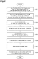
- an error of the part of the weighing hoppers 6 is detected as shown in FIG. 2 (step S1).
- Examples of the error of the weighing hopper 6 include an error during zero point correction by the weighing unit 11, over-scaling of the weighing hoppers 6, and a driving error in operating the weighing hoppers 6.
- the error during zero point correction is an error detected when a tare weight reset by the zero point correction is larger than a previous tare weight by a predetermined amount.
- the over-scaling is an error detected when a weighing value exceeds a predetermined range corresponding to the target weighing value.
- the driving error is an error detected when a step out or the like is caused in a driving unit (e.g., motor) for implementing the discharging operation of the weighing hoppers 6.
- the control unit 20 starts combination calculation based on a weighing value corresponding to mass of the article A held in each of the weighing hoppers 6 other than the part of the weighing hoppers 6 (step S2). More specifically, the control unit 20 removes the part of the weighing hoppers 6 corresponding to the detected error from combination calculation.
- the notification unit 14 gives notification about the error (step S3).
- the notification unit 14 displays, on the display screen 14A, a position and a number of the part of the weighing hoppers 6 corresponding to the detected error as shown in FIG. 3 .
- the operator can check the part of the weighing hoppers 6 corresponding to the detected error by visual recognition of the display screen 14A.
- FIG. 3 indicates the position of the weighing hopper 6 corresponding to the detected error by hatching, and the number "3" allocated to the corresponding weighing hopper 6 in an example of the combination weighing device 1 including the 16 weighing hoppers 6.
- step S4 the control unit 20 stops the discharging operation of the part of the weighing hoppers 6 (step S4).
- the control unit 20 also stops a discharging operation of the pool hopper 5 on the upstream side of the part of the weighing hopper 6, and a conveying operation of the radial feeder 4 on the upstream side of the part of the weighing hoppers 6.
- the control unit 20 continues the discharging operation of the weighing hoppers 6 other than the part of the weighing hoppers 6. Note that steps S2, S3 and S4 may be performed in no particular order or may be performed simultaneously.
- the part of the weighing hoppers 6 is removed by the operator (see step S5 in FIG. 4 ). Removal of the part of the weighing hoppers 6 can be detected by using the weighing unit 11.
- the control unit 20 continues combination calculation based on the weighing value corresponding to the mass of the article A held in each of the weighing hoppers 6 other than the part of the weighing hoppers 6, and continues the stop of the respective operations of the pool hopper 5 and the radial feeder 4 on the upstream side of the part of the weighing hoppers 6.
- the abnormal condition of the part of the weighing hoppers 6 is eliminated by the operator (step S6).
- the error of the weighing hopper 6 is an error during zero point correction, for example, the residual or attached matter of the weighing hopper 6 is removed.
- the error of the weighing hopper 6 is over-scaling, for example, the article A held in the weighing hopper 6 is discarded to a defective box or the like.
- the error of the weighing hopper 6 is a driving error, for example, the driving unit is repaired or replaced.
- the part of the weighing hoppers 6 is again attached by the operator (step S7).
- the state in which the part of the weighing hoppers 6 has been attached can be detected by using the weighing unit 11.
- the weighing unit 11 considers that the article A is not held in the part of the weighing hoppers 6, and performs zero point correction of the weighing value of the part of the weighing hoppers 6 (weighing value obtained by the weighing unit 11 in accordance with the mass of article A held in the part of the weighing hoppers 6) (step S8).
- control unit 20 returns (adds) the attached part of the weighing hoppers 6 to combination calculation (step S9). Specifically, after the weighing unit 11 performs zero point correction in the state in which the removed part of the weighing hoppers 6 has been attached, the control unit 20 operates the pool hopper 5 and the radial feeder 4 on the upstream side of the part of the weighing hoppers 6 to supply the article A to the part of the weighing hoppers 6, and continues combination calculation based on the weighing value corresponding to the mass of the article A held in each of the plurality of weighing hoppers 6 including the part of the weighing hoppers 6 (i.e., returns the part of the weighing hoppers 6 to combination calculation, and simultaneously restarts supply of the article A to the part of the weighing hoppers 6).
- a part of the weighing hoppers 6 of the combination weighing device 1 may be removed by the operator for maintenance such as cleaning during operation of the combination weighing device 1.
- the part of the weighing hoppers 6 is removed by the operator during operation of the combination weighing device 1 as shown in FIG. 5 (step S11).
- the control unit 20 starts combination calculation based on a weighing value corresponding to mass of the article A held in each of the weighing hoppers 6 other than the part of the weighing hoppers 6 (step S12).
- step S12 the control unit 20 stops respective operations of the pool hopper 5 and the radial feeder 4 on the upstream side of the part of the weighing hoppers 6.
- control unit 20 continues combination calculation based on the weighing value corresponding to the mass of the article A held in each of the weighing hoppers 6 other than the part of the weighing hoppers 6, and continues the stop of the respective operations of the pool hopper 5 and the radial feeder 4 on the upstream side of the part of the weighing hoppers 6.
- step S13 maintenance is performed for the part of the weighing hoppers 6 (step S13).
- steps S14 to S16 are similar to steps S7 to S9, respectively.
- a part of the weighing hoppers 6 of the combination weighing device 1 may be removed from combination calculation by the operator for maintenance such as cleaning during operation of the combination weighing device 1.
- an operation for removing the part of the weighing hoppers 6 from combination calculation is input by the operator during operation of the combination weighing device 1 as shown in FIG. 6 (step S21). This operation can be input via an operation input unit of the combination weighing device 1.
- the control unit 20 starts combination calculation based on a weighing value corresponding to mass of the article A held in each of the weighing hoppers 6 other than the part of the weighing hoppers 6 (step S22).
- the control unit 20 stops the operation of the part of the weighing hoppers 6 (step S23).
- the control unit 20 also stops the respective operations of the pool hopper 5 and the radial feeder 4 on the upstream side of the part of the weighing hoppers 6.
- step S24 the part of the weighing hoppers 6 is removed by the operator (step S24).
- the control unit 20 continues combination calculation based on the weighing value corresponding to the mass of the article A held in each of the weighing hoppers 6 other than the part of the weighing hoppers 6, and continues the stop of the respective operations of the pool hopper 5 and the radial feeder 4 on the upstream side of the part of the weighing hoppers 6.
- step S25 maintenance is performed for the part of the weighing hoppers 6 (step S25).
- steps S26 to S28 are similar to steps S7 to S9, respectively.
- the control unit 20 performs combination calculation based on a weighing value corresponding to mass of the article A held in each of the plurality of weighing hoppers 6, and continues combination calculation based on a weighing value corresponding to mass of the article A held in each of the weighing hoppers 6 other than a part of the weighing hoppers 6 in a state in which the part of the plurality of weighing hoppers 6 has been removed. Accordingly, even in the state in which a part of the weighing hoppers 6 has been removed to eliminate an abnormal condition currently caused, for example, combination calculation can be continued based on the weighing hoppers 6 other than the part of the weighing hoppers 6 without stopping the combination weighing device 1. Accordingly, an operation rate drop is avoidable.
- the weighing unit 11 performs zero point correction for a weighing value corresponding to a part of the weighing hoppers 6 when the part of the weighing hoppers 6 is attached after removal. In this manner, zero point correction of the weighing values of the part of the weighing hoppers 6 is performed to reduce a zero point error of the weighing unit 11 without stopping the combination weighing device 1 after the part of the weighing hoppers 6 are attached.
- the control unit 20 continues combination calculation based on a weighing value corresponding to mass of the article A held in each of the plurality of weighing hoppers 6 including a part of the weighing hoppers 6 when the weighing unit 11 performs zero point correction in a state in which the part of the weighing hoppers 6 after removal is again attached.
- the part of the weighing hoppers 6 can be again added to combination calculation without stopping the combination weighing device 1 after attachment of the part of the weighing hoppers 6 and zero point correction by the weighing unit 11.
- the control unit 20 starts combination calculation based on a weighing value corresponding to mass of the article A held in each of the weighing hoppers 6 other than the part of the weighing hoppers 6. In this manner, combination calculation based on the weighing value corresponding to the mass of the article A held in each of the weighing hoppers 6 other than the part of the weighing hoppers 6 can be started in response to the removal of the part of the weighing hoppers 6.
- the control unit 20 starts combination calculation based on a weighing value corresponding to mass of the article A held in each of the weighing hoppers 6 other than the part of the weighing hoppers 6. In this manner, combination calculation based on the weighing value corresponding to the mass of the article A held in each of the weighing hoppers 6 other than the part of the weighing hoppers 6 can be started in response to the error of the part of the weighing hoppers 6.
- the control unit 20 of the combination weighing device 1 starts combination calculation based on a weighing value corresponding to mass of the article A held in each of the weighing hoppers 6 other than the part of the weighing hoppers 6. In this manner, combination calculation based on the weighing value corresponding to the mass of the article A held in each of the weighing hoppers 6 other than the part of the weighing hoppers 6 can be started in response to input of the operation for removing the part of the weighing hoppers 6 from combination calculation.
- the control unit 20 of the combination weighing device 1 stops a discharging operation of the pool hopper 5 on the upstream side of the part of the weighing hopper 6, and a conveying operation of the radial feeder 4 on the upstream side of the part of the weighing hoppers 6. In this manner, continuous supply of the articles A to the attachment positions of the articles A is avoidable even after removal of the weighing hoppers 6.
- the combination weighing device 1 includes the notification unit 14 which gives notification about an error of a part of the weighing hoppers 6.
- the notification unit 14 which gives notification about an error of a part of the weighing hoppers 6.
- an error of a part of the weighing hoppers 6 included in the plurality of weighing hoppers 6 can be easily checked. Accordingly, the part of the weighing hoppers 6 can be easily removed from the plurality of weighing hoppers 6, for example.
- the weighing hoppers 6 are attachable to and detachable from the case 13.
- an abnormal condition can be eliminated after detachment of a part of the weighing hoppers 6 corresponding to the abnormal condition and discharge of the article A held in the corresponding weighing hopper 6.
- the necessity of providing an actuator or the like for discharging the articles A from the weighing hoppers 6 is eliminated. Size reduction and cost reduction of the device are therefore achievable.
- Removal of the weighing hoppers 6 and attachment of the weighing hoppers 6 are not required to be detected by the weighing unit 11. Removal of the weighing hoppers 6 and attachment of the weighing hoppers 6 may be detected by a detection unit separately provided.
- this detection unit may be constituted of a proximity sensor or the like provided for each of the plurality of weighing hoppers 6.
- the control unit 20 may continue combination calculation based on a weighing value corresponding to mass of the article A held in each of the weighing hoppers 6 other than the weighing hoppers 6 on the downstream side of the part of the pool hoppers 5. In this manner, combination calculation can continue without an operation rate drop of the combination weighing device 1 even in the state in which the part of the pool hoppers 5 has been removed from the plurality of pool hoppers 5.
- the combination weighing device 1 further includes a detection unit which detects attachment and detachment of each of the plurality of pool hoppers 5.
- this detection unit may be constituted of a proximity sensor or the like provided for each of the plurality of pool hoppers 5.
- the control unit 20 may continue combination calculation based on a weighing value corresponding to mass of the article A held in each of the weighing hoppers 6 other than the weighing hopper 6 on the upstream side of the part of the booster hoppers 7. In this manner, combination calculation can continue without an operation rate drop of the combination weighing device 1 even in the state in which the part of the booster hoppers 7 has been removed from the plurality of booster hoppers 7.
- the combination weighing device 1 further includes a detection unit which detects attachment and detachment of each of the plurality of booster hoppers 7.
- this detection unit may be constituted of a proximity sensor or the like provided for each of the plurality of booster hoppers 7.
- the control unit 20 may start combination calculation based on a weighing value corresponding to mass of the article A held in each of the weighing hoppers 6 other than the weighing hoppers 6 on at least one of occasions of detection of an error of a part of the weighing hoppers 6, detection of removal of a part of the weighing hoppers 6, and input of operation for removing a part of the weighing hoppers 6 from combination calculation.
- control unit 20 In the state in which a part of the weighing hoppers 6 is removed during operation of the combination weighing device 1, the control unit 20 is not required to stop the respective operations of the pool hopper 5 and the radial feeder 4 on the upstream side of the part of the weighing hoppers 6 depending on circumstances.
- a combination weighing device capable of reducing an operation rate drop.
Landscapes
- Physics & Mathematics (AREA)
- General Physics & Mathematics (AREA)
- Supply Of Fluid Materials To The Packaging Location (AREA)
- Weight Measurement For Supplying Or Discharging Of Specified Amounts Of Material (AREA)
Claims (10)
- Dispositif de pesage par combinaison comprenant :une unité de transport (4) configurée pour transporter un article ;une pluralité de premières trémies (5) chacune configurée pour recevoir l'article transporté par l'unité de transport, maintenir temporairement l'article reçu, et puis décharger l'article en aval ;une pluralité de deuxièmes trémies (6) prévues de manière amovible en aval de la pluralité de premières trémies, et chacune configurée pour recevoir l'article déchargé provenant de celle correspondante de la pluralité de premières trémies, maintenir temporairement l'article reçu, et puis décharger l'article en aval ;une unité de pesage (11) configurée pour peser l'article maintenu dans chacune de la pluralité de deuxièmes trémies, et obtenir une valeur de pesage correspondant à la masse de l'article ; etune unité de commande (20) configurée pour effectuer un calcul de combinaison afin de sélectionner une telle combinaison de valeurs de pesage dont une valeur totale devient une valeur de pesage cible, et décharger l'article à partir de la deuxième trémie correspondant à la combinaison,caractérisé en ce quel'unité de commande (20) est configurée pour effectuer le calcul de combinaison sur la base de la valeur de pesage correspondant à la masse de l'article maintenu dans chacune de la pluralité de deuxièmes trémies (6), etdans un état dans lequel une partie des deuxièmes trémies (6) a été retirée de la pluralité de deuxièmes trémies, l'unité de commande (20) est configurée pour continuer le calcul de combinaison sur la base de la valeur de pesage correspondant à la masse de l'article maintenu dans chacune de la pluralité de deuxièmes trémies autre que la partie des deuxièmes trémies.
- Dispositif de pesage par combinaison selon la revendication 1, dans lequel l'unité de pesage (11) est configurée pour effectuer une correction du point zéro de la valeur de pesage obtenue par l'unité de pesage et correspondant à la masse de l'article maintenu dans la partie des deuxièmes trémies lorsque la partie des deuxièmes trémies après le retrait est fixée.
- Dispositif de pesage par combinaison selon la revendication 2, dans lequel l'unité de commande (20) est configurée pour continuer le calcul de combinaison sur la base de la valeur de pesage correspondant à la masse de l'article maintenu dans chacune de la pluralité de deuxièmes trémies (6) comportant une partie des deuxièmes trémies lorsque l'unité de pesage effectue une correction de point zéro.
- Dispositif de pesage par combinaison selon l'une quelconque des revendications 1 à 3, dans lequel l'unité de commande (20) est configurée pour démarrer le calcul de combinaison sur la base de la valeur de pesage correspondant à la masse de l'article maintenu dans chacune des deuxièmes trémies (6) autre qu'une partie des deuxièmes trémies lorsque le retrait de la partie des deuxièmes trémies incluses dans la pluralité de deuxièmes trémies est détecté.
- Dispositif de pesage par combinaison selon l'une quelconque des revendications 1 à 3, dans lequel l'unité de commande (20) est configurée pour démarrer le calcul de combinaison sur la base de la valeur de pesage correspondant à la masse de l'article maintenu dans chacune des deuxièmes trémies (6) autre qu'une partie des deuxièmes trémies lorsqu'une erreur de la partie des deuxièmes trémies incluses dans la pluralité de deuxièmes trémies est détectée.
- Dispositif de pesée combinée selon l'une quelconque des revendications 1 à 3, dans lequel l'unité de commande (20) est configurée pour démarrer le calcul de combinaison sur la base de la valeur de pesage correspondant à la masse de l'article maintenu dans chacune des deuxièmes trémies (6) autre qu'une partie des deuxièmes trémies lorsqu'une opération de retrait de la partie des deuxièmes trémies incluses dans la pluralité de deuxièmes trémies du calcul de combinaison est entrée.
- Dispositif de pesage par combinaison selon l'une quelconque des revendications 1 à 6, dans lequel l'unité de commande (20) est configurée pour arrêter une opération de déchargement de la première trémie (5) en amont de la partie des deuxièmes trémies (6), et une opération de transport de l'unité de transport (4) en amont de la partie des deuxièmes trémies dans un état de retrait de la partie des deuxièmes trémies.
- Dispositif de pesage par combinaison selon la revendication 5, comprenant en outre une unité de notification (14) configurée pour donner une notification concernant l'erreur de la partie des deuxièmes trémies incluses dans la pluralité de deuxièmes trémies.
- Dispositif de pesage par combinaison selon l'une quelconque des revendications 1 à 8, dans lequelchacune de la pluralité de premières trémies (5) est prévue de manière amovible en aval de l'unité de transport (4), etdans un état de retrait d'une partie des premières trémies incluses dans la pluralité de premières trémies, l'unité de commande (20) continue le calcul de combinaison sur la base de la valeur de pesage correspondant à la masse de l'article maintenu dans chacune des deuxièmes trémies autre que la deuxième trémie en aval de la partie des premières trémies.
- Dispositif de pesage par combinaison selon l'une quelconque des revendications 1 à 9, comprenant en outre une pluralité de troisièmes trémies (7) prévues de manière amovible en aval de la pluralité de deuxièmes trémies (6), et chacune configurée pour recevoir l'article déchargé provenant de celle correspondante de la pluralité de deuxièmes trémies, maintenir temporairement l'article reçu, et puis décharger l'article en aval, dans lequel
dans un état de retrait d'une partie des troisièmes trémies de pesage incluses dans la pluralité de troisièmes trémies de pesage, l'unité de commande (20) continue le calcul de combinaison sur la base de la valeur de pesage correspondant à la masse de l'article maintenue dans chacune des deuxièmes des trémies autre que la deuxième trémie en amont de la partie des troisièmes trémies.
Applications Claiming Priority (1)
| Application Number | Priority Date | Filing Date | Title |
|---|---|---|---|
| JP2018163444A JP7061796B2 (ja) | 2018-08-31 | 2018-08-31 | 組合せ計量装置 |
Publications (2)
| Publication Number | Publication Date |
|---|---|
| EP3617671A1 EP3617671A1 (fr) | 2020-03-04 |
| EP3617671B1 true EP3617671B1 (fr) | 2022-03-30 |
Family
ID=66676321
Family Applications (1)
| Application Number | Title | Priority Date | Filing Date |
|---|---|---|---|
| EP19177191.4A Active EP3617671B1 (fr) | 2018-08-31 | 2019-05-29 | Dispositif de pesage par combinaison |
Country Status (4)
| Country | Link |
|---|---|
| US (1) | US11435220B2 (fr) |
| EP (1) | EP3617671B1 (fr) |
| JP (1) | JP7061796B2 (fr) |
| CN (1) | CN110873603A (fr) |
Families Citing this family (6)
| Publication number | Priority date | Publication date | Assignee | Title |
|---|---|---|---|---|
| JP7421805B2 (ja) * | 2020-03-19 | 2024-01-25 | 株式会社イシダ | 計量装置 |
| EP3882587B1 (fr) * | 2020-03-19 | 2022-05-11 | Ishida Co., Ltd. | Appareil de pesage |
| CN112179469B (zh) * | 2020-08-27 | 2022-04-22 | 广东精威智能机器有限公司 | 一种混料称量方法及混料设备 |
| JP7606205B2 (ja) * | 2020-11-06 | 2024-12-25 | 株式会社イシダ | 組合せ計量装置 |
| JP7597357B2 (ja) * | 2020-11-12 | 2024-12-10 | 株式会社イシダ | 組合せ計量装置 |
| EP4030152B1 (fr) * | 2021-01-13 | 2023-05-03 | ISHIDA CO., Ltd. | Dispositif de pesage par combinaison |
Citations (7)
| Publication number | Priority date | Publication date | Assignee | Title |
|---|---|---|---|---|
| EP0075479A2 (fr) | 1981-09-21 | 1983-03-30 | Kabushiki Kaisha Ishida Koki Seisakusho | Dispositif de pesage employant des trémies successives |
| EP0104084A2 (fr) | 1982-09-20 | 1984-03-28 | Kabushiki Kaisha Ishida Koki Seisakusho | Méthode de pesage combinatoire et dispositif y relatif |
| US4625817A (en) | 1982-04-16 | 1986-12-02 | Kabushiki Kaisha Ishida Koki Seisakusho | Method of zero adjustment for combinatorial weighing or counting system |
| US5379923A (en) | 1992-06-17 | 1995-01-10 | Eagle Packaging Corp. | Hopper for a weighing machine |
| EP0758078A2 (fr) | 1995-08-09 | 1997-02-12 | ISHIDA CO., Ltd. | Dispositif combinatoire de pesage ou de comptage |
| JP2005055187A (ja) | 2003-08-01 | 2005-03-03 | Ishida Co Ltd | 組合せ計量計数装置および組合せ計量計数方法 |
| JP2017138188A (ja) | 2016-02-03 | 2017-08-10 | 株式会社イシダ | 計量装置 |
Family Cites Families (22)
| Publication number | Priority date | Publication date | Assignee | Title |
|---|---|---|---|---|
| GB2074329B (en) * | 1980-03-25 | 1984-05-16 | Ishida Scale Mfg Co Ltd | Automatic weighing apparatus |
| AU539344B2 (en) * | 1980-09-09 | 1984-09-20 | K.K. Ishida Koki Seisakusho | Combination weighing apparatus |
| JPS58110830U (ja) * | 1982-01-22 | 1983-07-28 | 株式会社石田衡器製作所 | 計量装置 |
| US4569446A (en) * | 1982-10-29 | 1986-02-11 | Kelley-Perry, Incorporated | Method and apparatus for feeding a product including fines |
| DE3574407D1 (en) * | 1984-09-20 | 1989-12-28 | Ishida Scale Mfg Co Ltd | Weighing apparatus |
| JPS61104230A (ja) | 1984-10-26 | 1986-05-22 | Yamato Scale Co Ltd | 組合せ計量方法 |
| US4727947A (en) * | 1985-09-03 | 1988-03-01 | Ishida Scales Manufacturing Company, Ltd. | Span adjustment system and method |
| US4678046A (en) * | 1986-01-31 | 1987-07-07 | Package Machinery Company | Combination weighing apparatus for two combined products |
| CN2045848U (zh) | 1988-03-18 | 1989-10-11 | 杨增力 | 电子皮带秤比例配料装置 |
| US5211253A (en) * | 1991-10-17 | 1993-05-18 | The Paxall Group | Method and apparatus for combination weigher |
| DE69409700T2 (de) | 1993-03-08 | 1998-10-29 | Ishida Scale Mfg Co Ltd | Wiegesystem |
| US7446285B2 (en) * | 2002-04-24 | 2008-11-04 | Ishida Co., Ltd. | Foodstuffs processing apparatus with memo information device |
| JP4714514B2 (ja) * | 2005-06-30 | 2011-06-29 | 大和製衡株式会社 | 組合せ計量装置 |
| WO2007034655A1 (fr) | 2005-09-26 | 2007-03-29 | Masayoshi Nakajima | Dispositif de mesure combinée, système d’emballage et de fabrication de sac dotés de ce dispositif et système de mesure combinée |
| JP5048309B2 (ja) | 2006-04-14 | 2012-10-17 | 勝三 川西 | 組合せ秤 |
| CN101788328A (zh) | 2010-03-03 | 2010-07-28 | 江苏赛摩集团有限公司 | 一种平台秤的称量控制装置及其方法 |
| CN203893927U (zh) | 2014-02-22 | 2014-10-22 | 昆明钢铁控股有限公司 | 一种并联式水泥原料配料秤控制装置 |
| CN105806459B (zh) | 2015-01-16 | 2018-07-06 | 大和制衡株式会社 | 组合秤 |
| JP3197141U (ja) | 2015-02-09 | 2015-04-23 | 株式会社イシダ | 組合せ計量装置 |
| EP3786594B1 (fr) | 2015-12-17 | 2021-10-27 | Yamato Scale Co., Ltd. | Balance de combinaison |
| JP6732334B2 (ja) | 2016-12-28 | 2020-07-29 | 株式会社イシダ | 組合せ計量装置 |
| CN107705436B (zh) | 2017-09-21 | 2020-03-27 | 帮团成都电子商务有限责任公司 | 一种称重装置、重量处理方法及自动售货机 |
-
2018
- 2018-08-31 JP JP2018163444A patent/JP7061796B2/ja active Active
-
2019
- 2019-05-29 EP EP19177191.4A patent/EP3617671B1/fr active Active
- 2019-06-24 US US16/450,502 patent/US11435220B2/en active Active
- 2019-08-28 CN CN201910803868.8A patent/CN110873603A/zh active Pending
Patent Citations (7)
| Publication number | Priority date | Publication date | Assignee | Title |
|---|---|---|---|---|
| EP0075479A2 (fr) | 1981-09-21 | 1983-03-30 | Kabushiki Kaisha Ishida Koki Seisakusho | Dispositif de pesage employant des trémies successives |
| US4625817A (en) | 1982-04-16 | 1986-12-02 | Kabushiki Kaisha Ishida Koki Seisakusho | Method of zero adjustment for combinatorial weighing or counting system |
| EP0104084A2 (fr) | 1982-09-20 | 1984-03-28 | Kabushiki Kaisha Ishida Koki Seisakusho | Méthode de pesage combinatoire et dispositif y relatif |
| US5379923A (en) | 1992-06-17 | 1995-01-10 | Eagle Packaging Corp. | Hopper for a weighing machine |
| EP0758078A2 (fr) | 1995-08-09 | 1997-02-12 | ISHIDA CO., Ltd. | Dispositif combinatoire de pesage ou de comptage |
| JP2005055187A (ja) | 2003-08-01 | 2005-03-03 | Ishida Co Ltd | 組合せ計量計数装置および組合せ計量計数方法 |
| JP2017138188A (ja) | 2016-02-03 | 2017-08-10 | 株式会社イシダ | 計量装置 |
Non-Patent Citations (7)
| Title |
|---|
| ANONYMOUS: "A Chronicle of Achievement", PACKAGING - PROCESSING, BID ON EQUIPMENT, 1973, pages 1-12 - 33-35, XP093012590, Retrieved from the Internet <URL:www.bid-on-equipment.com> |
| ANONYMOUS: "Europe : Food wholesaler installs Ishida multihead weighing technology", FOOD NEWS INTERNATIONAL, 12 December 2014 (2014-12-12), pages 1 - 4, XP093012612 |
| ANONYMOUS: "Ishida launches mid-range multi weigher", ISHIDA EUROPE, 17 April 2003 (2003-04-17), pages 1, XP093012609 |
| ANONYMOUS: "MAREL", MULTIHEAD ADVANCED, 16 November 2016 (2016-11-16), pages 1 - 75, XP093012632 |
| ANONYMOUS: "Multihead Weigher CCW-R-2** Instruction Manual", MULTIHEAD WEIGHER CCW-R-2** INSTRUCTION MANUAL, 2016, pages 1 - 392, XP093012603 |
| ANONYMOUS: "Scanvaegt: ScanCombinator 5414", TECHNICAL HANDBOOK, 2 May 2002 (2002-05-02), pages 1 - 53, XP093012627 |
| ANONYMOUS: "Seafood solution", SCIENTISTLIVE, 1 April 2013 (2013-04-01), pages 1, XP093012625 |
Also Published As
| Publication number | Publication date |
|---|---|
| JP2020034507A (ja) | 2020-03-05 |
| EP3617671A1 (fr) | 2020-03-04 |
| US20200072656A1 (en) | 2020-03-05 |
| US11435220B2 (en) | 2022-09-06 |
| JP7061796B2 (ja) | 2022-05-02 |
| CN110873603A (zh) | 2020-03-10 |
Similar Documents
| Publication | Publication Date | Title |
|---|---|---|
| US11435220B2 (en) | Combination weighing device with selectable weighing hoppers | |
| EP3258227B1 (fr) | Appareil transporteur et appareil de pesage combiné | |
| JP7130335B2 (ja) | 組合せ計量装置 | |
| EP3620759B1 (fr) | Dispositif de pesage | |
| US10858127B2 (en) | Combination weighing device with control unit for targeted weight conveyance | |
| EP3564632B1 (fr) | Dispositif de pesage combiné | |
| US11125604B2 (en) | Combination weighing device including a movable and detachable discharge chute | |
| US11566933B2 (en) | Combination weighing device for controlling a conveying unit | |
| JP5701670B2 (ja) | 組合せ秤 | |
| EP3346242B1 (fr) | Dispositif de pesage de combinaison et procédé de pesage de combinaison | |
| JP7146626B2 (ja) | 計量装置 | |
| JP6664976B2 (ja) | 組合せ計量装置 | |
| EP3578471B1 (fr) | Système de pesage et de conditionnement | |
| EP3376185B1 (fr) | Dispositif de pesage par combinaison | |
| JP5752443B2 (ja) | 組合せ秤 | |
| JP5694005B2 (ja) | 組合せ秤 |
Legal Events
| Date | Code | Title | Description |
|---|---|---|---|
| PUAI | Public reference made under article 153(3) epc to a published international application that has entered the european phase |
Free format text: ORIGINAL CODE: 0009012 |
|
| STAA | Information on the status of an ep patent application or granted ep patent |
Free format text: STATUS: REQUEST FOR EXAMINATION WAS MADE |
|
| 17P | Request for examination filed |
Effective date: 20190529 |
|
| AK | Designated contracting states |
Kind code of ref document: A1 Designated state(s): AL AT BE BG CH CY CZ DE DK EE ES FI FR GB GR HR HU IE IS IT LI LT LU LV MC MK MT NL NO PL PT RO RS SE SI SK SM TR |
|
| AX | Request for extension of the european patent |
Extension state: BA ME |
|
| GRAP | Despatch of communication of intention to grant a patent |
Free format text: ORIGINAL CODE: EPIDOSNIGR1 |
|
| STAA | Information on the status of an ep patent application or granted ep patent |
Free format text: STATUS: GRANT OF PATENT IS INTENDED |
|
| INTG | Intention to grant announced |
Effective date: 20211021 |
|
| RIN1 | Information on inventor provided before grant (corrected) |
Inventor name: MURAKAMI, HIROKI Inventor name: KAMIGAITO, SATORU |
|
| GRAS | Grant fee paid |
Free format text: ORIGINAL CODE: EPIDOSNIGR3 |
|
| GRAA | (expected) grant |
Free format text: ORIGINAL CODE: 0009210 |
|
| STAA | Information on the status of an ep patent application or granted ep patent |
Free format text: STATUS: THE PATENT HAS BEEN GRANTED |
|
| AK | Designated contracting states |
Kind code of ref document: B1 Designated state(s): AL AT BE BG CH CY CZ DE DK EE ES FI FR GB GR HR HU IE IS IT LI LT LU LV MC MK MT NL NO PL PT RO RS SE SI SK SM TR |
|
| REG | Reference to a national code |
Ref country code: GB Ref legal event code: FG4D |
|
| REG | Reference to a national code |
Ref country code: CH Ref legal event code: EP |
|
| REG | Reference to a national code |
Ref country code: AT Ref legal event code: REF Ref document number: 1479614 Country of ref document: AT Kind code of ref document: T Effective date: 20220415 |
|
| REG | Reference to a national code |
Ref country code: DE Ref legal event code: R096 Ref document number: 602019012955 Country of ref document: DE |
|
| REG | Reference to a national code |
Ref country code: IE Ref legal event code: FG4D |
|
| REG | Reference to a national code |
Ref country code: LT Ref legal event code: MG9D |
|
| PG25 | Lapsed in a contracting state [announced via postgrant information from national office to epo] |
Ref country code: SE Free format text: LAPSE BECAUSE OF FAILURE TO SUBMIT A TRANSLATION OF THE DESCRIPTION OR TO PAY THE FEE WITHIN THE PRESCRIBED TIME-LIMIT Effective date: 20220330 Ref country code: RS Free format text: LAPSE BECAUSE OF FAILURE TO SUBMIT A TRANSLATION OF THE DESCRIPTION OR TO PAY THE FEE WITHIN THE PRESCRIBED TIME-LIMIT Effective date: 20220330 Ref country code: NO Free format text: LAPSE BECAUSE OF FAILURE TO SUBMIT A TRANSLATION OF THE DESCRIPTION OR TO PAY THE FEE WITHIN THE PRESCRIBED TIME-LIMIT Effective date: 20220630 Ref country code: LT Free format text: LAPSE BECAUSE OF FAILURE TO SUBMIT A TRANSLATION OF THE DESCRIPTION OR TO PAY THE FEE WITHIN THE PRESCRIBED TIME-LIMIT Effective date: 20220330 Ref country code: HR Free format text: LAPSE BECAUSE OF FAILURE TO SUBMIT A TRANSLATION OF THE DESCRIPTION OR TO PAY THE FEE WITHIN THE PRESCRIBED TIME-LIMIT Effective date: 20220330 Ref country code: BG Free format text: LAPSE BECAUSE OF FAILURE TO SUBMIT A TRANSLATION OF THE DESCRIPTION OR TO PAY THE FEE WITHIN THE PRESCRIBED TIME-LIMIT Effective date: 20220630 |
|
| REG | Reference to a national code |
Ref country code: NL Ref legal event code: MP Effective date: 20220330 |
|
| REG | Reference to a national code |
Ref country code: AT Ref legal event code: MK05 Ref document number: 1479614 Country of ref document: AT Kind code of ref document: T Effective date: 20220330 |
|
| PG25 | Lapsed in a contracting state [announced via postgrant information from national office to epo] |
Ref country code: LV Free format text: LAPSE BECAUSE OF FAILURE TO SUBMIT A TRANSLATION OF THE DESCRIPTION OR TO PAY THE FEE WITHIN THE PRESCRIBED TIME-LIMIT Effective date: 20220330 Ref country code: GR Free format text: LAPSE BECAUSE OF FAILURE TO SUBMIT A TRANSLATION OF THE DESCRIPTION OR TO PAY THE FEE WITHIN THE PRESCRIBED TIME-LIMIT Effective date: 20220701 Ref country code: FI Free format text: LAPSE BECAUSE OF FAILURE TO SUBMIT A TRANSLATION OF THE DESCRIPTION OR TO PAY THE FEE WITHIN THE PRESCRIBED TIME-LIMIT Effective date: 20220330 |
|
| PG25 | Lapsed in a contracting state [announced via postgrant information from national office to epo] |
Ref country code: NL Free format text: LAPSE BECAUSE OF FAILURE TO SUBMIT A TRANSLATION OF THE DESCRIPTION OR TO PAY THE FEE WITHIN THE PRESCRIBED TIME-LIMIT Effective date: 20220330 |
|
| PG25 | Lapsed in a contracting state [announced via postgrant information from national office to epo] |
Ref country code: SM Free format text: LAPSE BECAUSE OF FAILURE TO SUBMIT A TRANSLATION OF THE DESCRIPTION OR TO PAY THE FEE WITHIN THE PRESCRIBED TIME-LIMIT Effective date: 20220330 Ref country code: SK Free format text: LAPSE BECAUSE OF FAILURE TO SUBMIT A TRANSLATION OF THE DESCRIPTION OR TO PAY THE FEE WITHIN THE PRESCRIBED TIME-LIMIT Effective date: 20220330 Ref country code: RO Free format text: LAPSE BECAUSE OF FAILURE TO SUBMIT A TRANSLATION OF THE DESCRIPTION OR TO PAY THE FEE WITHIN THE PRESCRIBED TIME-LIMIT Effective date: 20220330 Ref country code: PT Free format text: LAPSE BECAUSE OF FAILURE TO SUBMIT A TRANSLATION OF THE DESCRIPTION OR TO PAY THE FEE WITHIN THE PRESCRIBED TIME-LIMIT Effective date: 20220801 Ref country code: ES Free format text: LAPSE BECAUSE OF FAILURE TO SUBMIT A TRANSLATION OF THE DESCRIPTION OR TO PAY THE FEE WITHIN THE PRESCRIBED TIME-LIMIT Effective date: 20220330 Ref country code: EE Free format text: LAPSE BECAUSE OF FAILURE TO SUBMIT A TRANSLATION OF THE DESCRIPTION OR TO PAY THE FEE WITHIN THE PRESCRIBED TIME-LIMIT Effective date: 20220330 Ref country code: CZ Free format text: LAPSE BECAUSE OF FAILURE TO SUBMIT A TRANSLATION OF THE DESCRIPTION OR TO PAY THE FEE WITHIN THE PRESCRIBED TIME-LIMIT Effective date: 20220330 Ref country code: AT Free format text: LAPSE BECAUSE OF FAILURE TO SUBMIT A TRANSLATION OF THE DESCRIPTION OR TO PAY THE FEE WITHIN THE PRESCRIBED TIME-LIMIT Effective date: 20220330 |
|
| PG25 | Lapsed in a contracting state [announced via postgrant information from national office to epo] |
Ref country code: PL Free format text: LAPSE BECAUSE OF FAILURE TO SUBMIT A TRANSLATION OF THE DESCRIPTION OR TO PAY THE FEE WITHIN THE PRESCRIBED TIME-LIMIT Effective date: 20220330 Ref country code: IS Free format text: LAPSE BECAUSE OF FAILURE TO SUBMIT A TRANSLATION OF THE DESCRIPTION OR TO PAY THE FEE WITHIN THE PRESCRIBED TIME-LIMIT Effective date: 20220730 Ref country code: AL Free format text: LAPSE BECAUSE OF FAILURE TO SUBMIT A TRANSLATION OF THE DESCRIPTION OR TO PAY THE FEE WITHIN THE PRESCRIBED TIME-LIMIT Effective date: 20220330 |
|
| REG | Reference to a national code |
Ref country code: DE Ref legal event code: R026 Ref document number: 602019012955 Country of ref document: DE |
|
| REG | Reference to a national code |
Ref country code: CH Ref legal event code: PL |
|
| PLBI | Opposition filed |
Free format text: ORIGINAL CODE: 0009260 |
|
| PLAX | Notice of opposition and request to file observation + time limit sent |
Free format text: ORIGINAL CODE: EPIDOSNOBS2 |
|
| REG | Reference to a national code |
Ref country code: BE Ref legal event code: MM Effective date: 20220531 |
|
| PG25 | Lapsed in a contracting state [announced via postgrant information from national office to epo] |
Ref country code: MC Free format text: LAPSE BECAUSE OF FAILURE TO SUBMIT A TRANSLATION OF THE DESCRIPTION OR TO PAY THE FEE WITHIN THE PRESCRIBED TIME-LIMIT Effective date: 20220330 Ref country code: LU Free format text: LAPSE BECAUSE OF NON-PAYMENT OF DUE FEES Effective date: 20220529 Ref country code: LI Free format text: LAPSE BECAUSE OF NON-PAYMENT OF DUE FEES Effective date: 20220531 Ref country code: DK Free format text: LAPSE BECAUSE OF FAILURE TO SUBMIT A TRANSLATION OF THE DESCRIPTION OR TO PAY THE FEE WITHIN THE PRESCRIBED TIME-LIMIT Effective date: 20220330 Ref country code: CH Free format text: LAPSE BECAUSE OF NON-PAYMENT OF DUE FEES Effective date: 20220531 |
|
| 26 | Opposition filed |
Opponent name: MAREL A/S Effective date: 20221229 |
|
| PG25 | Lapsed in a contracting state [announced via postgrant information from national office to epo] |
Ref country code: IE Free format text: LAPSE BECAUSE OF NON-PAYMENT OF DUE FEES Effective date: 20220529 Ref country code: FR Free format text: LAPSE BECAUSE OF NON-PAYMENT OF DUE FEES Effective date: 20220530 |
|
| PG25 | Lapsed in a contracting state [announced via postgrant information from national office to epo] |
Ref country code: SI Free format text: LAPSE BECAUSE OF FAILURE TO SUBMIT A TRANSLATION OF THE DESCRIPTION OR TO PAY THE FEE WITHIN THE PRESCRIBED TIME-LIMIT Effective date: 20220330 Ref country code: BE Free format text: LAPSE BECAUSE OF NON-PAYMENT OF DUE FEES Effective date: 20220531 |
|
| PLBB | Reply of patent proprietor to notice(s) of opposition received |
Free format text: ORIGINAL CODE: EPIDOSNOBS3 |
|
| PG25 | Lapsed in a contracting state [announced via postgrant information from national office to epo] |
Ref country code: IT Free format text: LAPSE BECAUSE OF FAILURE TO SUBMIT A TRANSLATION OF THE DESCRIPTION OR TO PAY THE FEE WITHIN THE PRESCRIBED TIME-LIMIT Effective date: 20220330 |
|
| PLAY | Examination report in opposition despatched + time limit |
Free format text: ORIGINAL CODE: EPIDOSNORE2 |
|
| PLBC | Reply to examination report in opposition received |
Free format text: ORIGINAL CODE: EPIDOSNORE3 |
|
| PG25 | Lapsed in a contracting state [announced via postgrant information from national office to epo] |
Ref country code: MK Free format text: LAPSE BECAUSE OF FAILURE TO SUBMIT A TRANSLATION OF THE DESCRIPTION OR TO PAY THE FEE WITHIN THE PRESCRIBED TIME-LIMIT Effective date: 20220330 Ref country code: CY Free format text: LAPSE BECAUSE OF FAILURE TO SUBMIT A TRANSLATION OF THE DESCRIPTION OR TO PAY THE FEE WITHIN THE PRESCRIBED TIME-LIMIT Effective date: 20220330 |
|
| PG25 | Lapsed in a contracting state [announced via postgrant information from national office to epo] |
Ref country code: HU Free format text: LAPSE BECAUSE OF FAILURE TO SUBMIT A TRANSLATION OF THE DESCRIPTION OR TO PAY THE FEE WITHIN THE PRESCRIBED TIME-LIMIT; INVALID AB INITIO Effective date: 20190529 |
|
| PG25 | Lapsed in a contracting state [announced via postgrant information from national office to epo] |
Ref country code: MT Free format text: LAPSE BECAUSE OF FAILURE TO SUBMIT A TRANSLATION OF THE DESCRIPTION OR TO PAY THE FEE WITHIN THE PRESCRIBED TIME-LIMIT Effective date: 20220330 |
|
| APBP | Date of receipt of notice of appeal recorded |
Free format text: ORIGINAL CODE: EPIDOSNNOA2O |
|
| APAH | Appeal reference modified |
Free format text: ORIGINAL CODE: EPIDOSCREFNO |
|
| APBQ | Date of receipt of statement of grounds of appeal recorded |
Free format text: ORIGINAL CODE: EPIDOSNNOA3O |
|
| PGFP | Annual fee paid to national office [announced via postgrant information from national office to epo] |
Ref country code: DE Payment date: 20250519 Year of fee payment: 7 |
|
| PG25 | Lapsed in a contracting state [announced via postgrant information from national office to epo] |
Ref country code: TR Free format text: LAPSE BECAUSE OF FAILURE TO SUBMIT A TRANSLATION OF THE DESCRIPTION OR TO PAY THE FEE WITHIN THE PRESCRIBED TIME-LIMIT Effective date: 20220330 |
|
| PGFP | Annual fee paid to national office [announced via postgrant information from national office to epo] |
Ref country code: GB Payment date: 20260324 Year of fee payment: 8 |