EP3617698A1 - Verfahren zur erkennung von oberflächenbruchfehlern in der gehärteten oberfläche einer lagerkomponente, insbesondere eines lagers einer windkraftturbine - Google Patents
Verfahren zur erkennung von oberflächenbruchfehlern in der gehärteten oberfläche einer lagerkomponente, insbesondere eines lagers einer windkraftturbine Download PDFInfo
- Publication number
- EP3617698A1 EP3617698A1 EP18191408.6A EP18191408A EP3617698A1 EP 3617698 A1 EP3617698 A1 EP 3617698A1 EP 18191408 A EP18191408 A EP 18191408A EP 3617698 A1 EP3617698 A1 EP 3617698A1
- Authority
- EP
- European Patent Office
- Prior art keywords
- coils
- row
- coil
- transmitting
- receiving
- Prior art date
- Legal status (The legal status is an assumption and is not a legal conclusion. Google has not performed a legal analysis and makes no representation as to the accuracy of the status listed.)
- Withdrawn
Links
Images

Classifications
-
- G—PHYSICS
- G01—MEASURING; TESTING
- G01M—TESTING STATIC OR DYNAMIC BALANCE OF MACHINES OR STRUCTURES; TESTING OF STRUCTURES OR APPARATUS, NOT OTHERWISE PROVIDED FOR
- G01M13/00—Testing of machine parts
- G01M13/04—Bearings
-
- G—PHYSICS
- G01—MEASURING; TESTING
- G01N—INVESTIGATING OR ANALYSING MATERIALS BY DETERMINING THEIR CHEMICAL OR PHYSICAL PROPERTIES
- G01N27/00—Investigating or analysing materials by the use of electric, electrochemical, or magnetic means
- G01N27/72—Investigating or analysing materials by the use of electric, electrochemical, or magnetic means by investigating magnetic variables
- G01N27/82—Investigating or analysing materials by the use of electric, electrochemical, or magnetic means by investigating magnetic variables for investigating the presence of flaws
- G01N27/90—Investigating or analysing materials by the use of electric, electrochemical, or magnetic means by investigating magnetic variables for investigating the presence of flaws using eddy currents
- G01N27/904—Investigating or analysing materials by the use of electric, electrochemical, or magnetic means by investigating magnetic variables for investigating the presence of flaws using eddy currents with two or more sensors
-
- G—PHYSICS
- G01—MEASURING; TESTING
- G01N—INVESTIGATING OR ANALYSING MATERIALS BY DETERMINING THEIR CHEMICAL OR PHYSICAL PROPERTIES
- G01N27/00—Investigating or analysing materials by the use of electric, electrochemical, or magnetic means
- G01N27/72—Investigating or analysing materials by the use of electric, electrochemical, or magnetic means by investigating magnetic variables
- G01N27/82—Investigating or analysing materials by the use of electric, electrochemical, or magnetic means by investigating magnetic variables for investigating the presence of flaws
- G01N27/90—Investigating or analysing materials by the use of electric, electrochemical, or magnetic means by investigating magnetic variables for investigating the presence of flaws using eddy currents
- G01N27/9046—Investigating or analysing materials by the use of electric, electrochemical, or magnetic means by investigating magnetic variables for investigating the presence of flaws using eddy currents by analysing electrical signals
-
- G—PHYSICS
- G01—MEASURING; TESTING
- G01N—INVESTIGATING OR ANALYSING MATERIALS BY DETERMINING THEIR CHEMICAL OR PHYSICAL PROPERTIES
- G01N27/00—Investigating or analysing materials by the use of electric, electrochemical, or magnetic means
- G01N27/72—Investigating or analysing materials by the use of electric, electrochemical, or magnetic means by investigating magnetic variables
- G01N27/82—Investigating or analysing materials by the use of electric, electrochemical, or magnetic means by investigating magnetic variables for investigating the presence of flaws
- G01N27/90—Investigating or analysing materials by the use of electric, electrochemical, or magnetic means by investigating magnetic variables for investigating the presence of flaws using eddy currents
- G01N27/9013—Arrangements for scanning
- G01N27/902—Arrangements for scanning by moving the sensors
Definitions
- the invention relates to a method for detecting surface breaking defects in the hardened surface of a bearing component, especially of a bearing of a wind turbine.
- Bearings are used in many various applications for connecting two machine parts which are rotatable relative to each other. Especially in large applications like a wind turbine respectively large bearings are used, with bearing rings having a diameter of one or several meters.
- the surface of such a bearing respectively a bearing ring, especially in large applications, is hardened.
- an induction hardening method is used for hardening the surface at least in its upper surface layer.
- the contact surfaces, on which the rolling elements are rolling is processed this way, as this surface of the respective ring is highly stressed and loaded.
- MPI magnetic particle inspection
- the invention refers to a method for detecting surface breaking defects in the hardened surface of a bearing component, especially of a bearing of a wind turbine, which is characterized in that the surface is scanned with a detecting device comprising an array of coils with at least one coil being controlled as a transmitting coil generating a magnetic field inducing an eddy current in the surface and at least one coil being controlled as a receiving coil measuring a magnetic field generated by the eddy current and providing respective measurement signals, and a control device for processing the measurement signals.
- the detection of surface breaking defects or surface discontinuities resulting from fissures or gaps in the hardened surface of the bearing component is performed by an eddy current inspection.
- a detecting device is used for scanning the surface under investigation and for receiving and processing measurement signals from the surface, which signals are influenced by discontinuities or inhomogeneities in the surface under investigation, compared to areas with a homogeneous surface.
- the detecting device For scanning the surface the detecting device comprises an array of coils, with at least one coil being controlled as a transmitting coil generating a magnetic field inducing an eddy current in the surface.
- a control device is used for controlling a coil, which is then acting as a transmitting coil, for generating a magnetic field in the surrounding of the coil.
- This magnetic field interacts with the bearing component respectively the surface and the surface region, and induces an eddy current in the surface and subsurface region in the respective scanning area.
- This eddy current in turn generates a magnetic field, which interacts with a second coil, which is controlled as a receiving coil by the control device.
- the magnetic field generated by the eddy current induces a current and therefore a respective signal in the receiving or measuring coil. This signal is received by the control device and processed by the control device.
- the received signal from a homogeneous area is different to a signal received from an area with a fissure or gap, which interferes the surface and subsurface region and therefore the eddy current and finally influences the magnetic field generated by the eddy current.
- two adjacent coils are simultaneously controlled as transmitting coils and two coils adjacent to the transmitting coils are controlled as receiving coils.
- the transmitting coils are arranged side by side in a respective row, while the two receiving coils are also arranged adjacent to the transmitting coils, but distanced from each other, so that each receiving coil receives a separate signal resulting from the eddy current from a separate region. This enhances the speed of detection.
- the array of the detecting device may comprise only one row of coils, in a preferred alternative the array may comprise at least two rows of coils, with the rows being arranged offset to each other.
- the second row is offset at half of the distance of two adjacent coils of the first row, with the distance of the coils in a second row being the same as the distance of the coils in the first row. This for example allows measuring in two separate rows, either simultaneously or intermitted. It also is advantageous as the speed of the scanning process is advanced.
- two adjacent coils in a row are controlled as transmitting coils and the two receiving coils are positioned at both sides of the two transmitting coils in the same row.
- both the transmitting and the receiving coils are arranged in the same row.
- This method alternative is therefore relevant for both alternatives comprising only one coil row or comprising two coil rows.
- the rows as already mentioned, may be controlled intermittedly, so that a measurement is performed by the coils of a first row and, after receiving the measurement signals, another cycle is performed by controlling the respective coils of the second row etc.
- the transmitting coils are arranged side by side, and the one receiving coil is arranged to the left of the one receiving coil, while the other receiving coil is arranged to the right of the other transmitting coil. Therefore, all four coils used for the detection process are arranged side by side.
- two adjacent coils in a row are controlled as transmitting coils and the first receiving coil is adjacent to one of the transmitting coils in the same row and the second receiving coil is in the second row and is adjacent to and centered between the transmitting coils.
- the transmitting coils are again arranged side by side.
- the first receiving coil is for example arranged to the left of the left transmitting coil.
- the second receiving coil is arranged in the second row and is distanced from the first receiving coil. It is placed in the center or between the transmitting coil, due to the row offset.
- the first receiving coil receives a measurement signal based on the eddy current mainly induced by the neighboring transmitting coil.
- the second receiving coil receives a measurement signal which is based on the eddy currents induced by both transmitting coils, due to the offset of the second row to the first row both in the direction of the respective rows and in the direction perpendicular to that.
- This second receiving coil therefore receives a measurement signal which is based on the overlaying eddy currents induced by the transmitting coils. It is obvious that this arrangement allows a detection in a direction perpendicular to the respective row direction. Therefore, with this inventive embodiment, a simultaneous signal detection in a first direction perpendicular to the row direction and in a second direction perpendicular to the row direction is simultaneously possible. This is also very advantageous for either the speed of the scanning process or for the local resolution of the scanning process.
- the detecting device used for performing the inventive method may comprise one coil row or at least two coil rows offset to each other.
- the control device may control the respective coils in a way that from one control period to the next control period the transmitting and receiving coils shift within the row by one adjacent coil over the whole row and back or starting again at the same row end.
- two center transmitting coils and two receiving coils arranged at the left and right side of the transmitting coils are used for the scanning process and are respectively controlled by the control device.
- the scanning or detecting device comprises a row with more than four coils, for example ten, fifteen or twenty coils
- the respective coils used for a scanning cycle or control period move along the row from one scanning cycle to the next or from one control period to the next. Therefore, a line scan for example over the width of a bearing ring can be easily performed by simply changing the control of the needed coils.
- the control frequency is high several hundred scanning cycles or control periods per second can be performed, so that a high-speed scanning is possible. This also allows that the same location is scanned several times due to the very high scanning frequency, so that for each location more than one scanning result is given, which can be respectively processed by the control device in order to evaluate a very precise and well-founded signal map.
- the transmitting and receiving coils shift from row to row and within the row by one adjacent coil over the whole row and back or starting again at the same row end. While in the previously discussed embodiment, the transmitting coils are always in the same row, in this embodiment the transmitting and receiving coils move from one row to the other from one scanning cycle to the next scanning cycle. In a first scanning cycle the transmitting coils are in the first row with one receiving coil being adjacent to one of the transmitting coils, while the other receiving coil is in the second row. In the second scanning cycle the transmitting coils are in the second row, with one receiving coil also being in the second row, but the other receiving coil being in the first row.
- the coils respectively the coil functions jump from row to row in a respective scanning cycle. Due to the offset and the fact, that the coil function also changes along the respective rows, the respective coil functions change in a zig-zag manner along the row direction.
- This embodiment allows for the measurement in respective perpendicular direction with a very high scanning speed and a very high local resolution, as the respective measurements change from scanning cycle to scanning cycle only for the half-gap distance between two adjacent coils due to the row offset.
- a detecting device is used with an array of coils which is at least as wide as the bearing component. This allows for performing a whole scan over the bearing component width without the need of relocating the scanning device. It is therefore only necessary to move the device along the inner or outer circumference of the respective bearing ring for measuring the whole signal map.
- the row is longer than the width of the component, while the control device is able to control only the coils which are needed for providing a whole line scan over the component width. This allows for the use of one detecting device for detecting various bearing components or bearing rings with varying widths.
- each signal is clearly located in the line direction and the circumferential direction or moving direction of the detecting device along the object. This allows to create a complete signal map with a high local resolution regarding the scan surface.
- the invention furthermore relates to a detecting device for use in a method as described above, comprising an array of coils arranged in at least one row in a control device adapted to control the coils according to the method as described above.
- the row comprises more than four coils.
- the inventive detecting device may comprise two rows each comprising more than four coils, with the rows being arranged offset to each other.
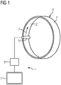
- Fig. 1 shows an inventive detecting device 1 used for scanning a surface 2 of a bearing component 3, here for example an outer bearing ring 4, whose surface 2 is in use, for example in a wind turbine, loaded by the rolling elements rolling along the surface 2.
- the rolling elements are not shown in fig. 1 .
- the detecting device 1 comprises a coil housing 5 accommodating a respective number of coils, which are not shown in fig. 1 , which coils are arranged in at least one row extending over the length of the housing 5, with the housing 5 being wider than the surface 2, so that the coil row is at least as long as the width of the surface 2 or preferably longer.
- the device 1 furthermore comprises a control device 6 used for controlling the coil array respectively the respective coils for switching their function from a transmitting coil to a receiving coil as explained below.
- the control device 6 furthermore comprises a respective controller being adapted to process the respective measurement signal received from the receiving coils of the coil array and for analyzing them for example in the form of a signal map displaying the respective localized measurement signals over the area of the surface 2.
- a signal map displaying the respective localized measurement signals over the area of the surface 2.
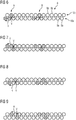
- Figs. 2 to 9 show respective embodiments of the coil arrangement respectively the coil array of the detecting device 1 respectively the coil housing 5.
- Fig. 2 shows a coil arrangement 8 comprising only one row of respective coils 9, with each row being separately controlled by the control device 6.
- the coils 9 are controlled for performing a line scan along the row 10 for measuring respective measurement signals.
- the coil array 8 is used for performing an eddy current measurement, with the received measurement signals being influenced from the local surface properties of the area, where the eddy current, which induces the respective measurement signal in the receiving coil, flows.
- the control device 7 in this embodiment controls during one scanning cycle or control period four coils 9 in their function, the other coils 9 are not controlled and therefore do not participate during this scanning cycle.
- Two coils 9 are controlled as transmitting coils T, which transmitting coils T are adjacent to each other.
- two receiving coils R which receive the respective measurement signal, are respectively controlled by the control device 6.
- the current flows through the transmitting coils T, which generate a magnetic field which couples into the surface 2.
- This magnetic field induces eddy current in the surface 2.
- This eddy current again creates a magnetic field at the surface 2, which field interacts with or is measured by the receiving coils R, as a current is induced in these receiving coils, which creates the respective measurement signal, which is gathered by the control device 6.
- the measurement direction is along the row 10, here in a horizontal direction.
- the next scanning cycle or control period starts, which is shown in fig. 3 .
- the control device 7 now changes the functionality of some of the coils 9. In fact, the functionality jumps or shifts to the right by one coil 9. Again, two transmitting coils are controlled by the control device 7, again being adjacent to each other, and two receiving coils R receiving the measurement signals are controlled by the control device 6. The measurement direction has not changed, as the arrows H indicate.
- This scanning cycle provides measurement signals from other, offset locations along the row 10 and therefore along the surface 2.
- Fig. 4 shows another embodiment of a coil array 8 used in an inventive detection device 10.
- This coil array comprises two rows 10a and 10b, each comprising respective coils 9a and 9b.
- the rows 10a, 10b are obviously shifted in the row direction by one half coil gap, so that the coils 9b are centered between two coils 9a.
- the control device 6 again controls two coils 9 as transmitting coils T, which transmitting coils T are again adjacent to each other, see fig. 4 .
- the transmitting coils T are arranged in the row 10a.
- a coil 9 is controlled as a receiving coil R, this is in this stage the coil 9 most left in the row. Due to this arrangement, comparable to figs. 2 and 3 , the eddy current measurement is performed in the direction as shown by arrow H, i.e. the horizontal direction of the row 10a.
- a second receiving coil R is controlled in the second row 10b.
- the second receiving coil R is spaced apart from the first receiving coil R and is centered between the two transmitting coils T.
- This receiving coil R measures the eddy current induced in the surface 2 of both transmitting coils T, as they are adjacent to each other and their respective magnetic fields overlap, therefore also the generated eddy current is the result of both transmitting coils T.
- the measuring direction indicated by the arrow V is perpendicular to the measuring direction H. Therefore, this embodiment allows for two different measuring directions, one horizontal and the other vertical, which is very advantageous for securing the defect detection indications in both directions.
- Fig. 5 shows the second scanning cycle or control period. Again, the respective coils are shifted by one coil along the respective coils 10a, 10b.
- the control device 6 controls two transmitting coils T and two receiving coils R, one again being to the left of the two transmitting coils, but in the same row 10a, while the second receiving coil is in the second row 10b.
- the scanning proceeds along the lines with the high scanning frequency, so that again each location is scanned more than one time, also a fairly fast speed scan is realized.
- the local resolution is very fine and determined by the gap or distance between the respective coils 9 in the respective rows 10 respectively 10a, 10b.
- Fig. 6 shows a coil array 8 again comprising two separate rows 10a, 10b, with the row 10b being offset for half of the gaps between the coils of row 10a.
- Each row comprises a bunch of coils 9a and 9b.
- two coil clusters A and B are simultaneously controlled by the control device 6 in the coil array 8 with the coil clusters A, B being spaced apart from each other and arranged in a way, that, when the respective line scans are performed, each coil cluster A, B scans half of the respective array length.
- each cluster A, B comprises two transmitting coils T adjacent to each other, again controlled for example in row 10a.
- a first receiving coil R is controlled in the same row 10a left to the transmitting coils T, while a second receiving coil R is controlled in the row 10b, distanced to the first receiving coil R in row 10a, and centered between the transmitting coils T.
- Fig. 7 shows the second scanning cycle or control period.
- the control device 6 now controls the respective coils 9a, 9b and therefore the respective coil function in a different way compared to figs. 5 and 6 .
- the two transmitting coils T are now in the second row 10a, but shifted in the line direction for the half gap length between two coils.
- the first receiving coil R as now shifted to the second row 10b, but is still to the left of the two transmitting coils T.
- the second receiving coil R has now shifted to the first row 10a and for a half gap width to the right, but is still centered between the two transmitting coils.
- the functionality of the respective coils of the respective clusters A, B has not only changed in the row direction, but also in the vertical direction from row to row. This also has an influence on the direction of measurement and the local resolution.
- the direction in the horizontal direction indicated by the arrow H is still the same, but the direction in the vertical direction indicated by the arrow V, has changed, as the transmitting coils T are now in the second row 10b and the respective receiving coil R is in the first row 10a.
- the scanning location has also only shifted for a half gap regarding the vertical scanning direction V, and a half gap and the vertical row distance regarding the horizontal scanning direction H. It is obvious that by this respective control method the local resolution can be further enhanced.
- Fig, 8 shows the third scanning cycle or control period. Again, the functionality of the respective coils changes, in this scanning cycle the two transmitting coils T are again in the first row 10a together with the first receiving coil R, while the second receiving coil R is again in the second row 10b.
- the setup is comparable to fig. 6 , but shifted in both rows 10a, 10b by one coil. But referred to the previous second scanning cycle again there is a change in the vertical scanning direction V and a local shift of the scanning position in the row direction only for a half gap width and in the horizontal direction for a half gap width and the row distance. The same setup is again given for both clusters A and B.
- figs. 4 and 5 due to the switching of the functionality between the rows 10a, 10b, more measurement signals are received during the scan without any relevant influence regarding the measurement or scanning speed due to the relatively high frequency of several hundred measurement or scanning cycles per second.
- Fig. 9 finally shows the forth scanning cycle or control period. Again, the functionality switches between the rows 10a, 10b, the two transmitting coils T and the one receiving coil R are now again in the second row 10a, compared to fig. 7 , while the second receiving coil R is in the first row 10a. Again, the respective half shift is given, with the enhanced local resolution.
- the next line scan can start directly at the end of the finished line scan, with the coil array being moved along the surface 2 in the next scanning position.
- This second line scan may now be performed backwards or in the reverse direction as the previous line scan.
- the eddy current inspection together with the inventive detecting device allows for a very accurate and precise scanning with a high resolution of the respective surface 2 and therefore a very accurate detection of any kind of surface defects, especially in the form of fissures, gaps or little holes, even if these defects are very small.
- Fissures or gaps or breaks with a width and depth of less than 1 mm and the length of approximately 1 mm or even less can be detected based on the measurement signals, so that a very precise wear detection is possible and any relevant wear can be recognized at a very early stage.
Landscapes
- Chemical & Material Sciences (AREA)
- Physics & Mathematics (AREA)
- General Physics & Mathematics (AREA)
- Life Sciences & Earth Sciences (AREA)
- Electrochemistry (AREA)
- Health & Medical Sciences (AREA)
- Chemical Kinetics & Catalysis (AREA)
- Analytical Chemistry (AREA)
- Biochemistry (AREA)
- General Health & Medical Sciences (AREA)
- Immunology (AREA)
- Pathology (AREA)
- Investigating Or Analyzing Materials By The Use Of Magnetic Means (AREA)
Priority Applications (3)
| Application Number | Priority Date | Filing Date | Title |
|---|---|---|---|
| EP18191408.6A EP3617698A1 (de) | 2018-08-29 | 2018-08-29 | Verfahren zur erkennung von oberflächenbruchfehlern in der gehärteten oberfläche einer lagerkomponente, insbesondere eines lagers einer windkraftturbine |
| EP19761731.9A EP3827254B1 (de) | 2018-08-29 | 2019-08-07 | Verfahren zur erkennung von oberflächenbruchfehlern in der gehärteten oberfläche einer lagerkomponente, insbesondere eines lagers einer windkraftturbine |
| PCT/EP2019/071160 WO2020043447A1 (en) | 2018-08-29 | 2019-08-07 | Method for detecting surface breaking defects in the hardened surface of a bearing component, especially of a bearing of a wind turbine |
Applications Claiming Priority (1)
| Application Number | Priority Date | Filing Date | Title |
|---|---|---|---|
| EP18191408.6A EP3617698A1 (de) | 2018-08-29 | 2018-08-29 | Verfahren zur erkennung von oberflächenbruchfehlern in der gehärteten oberfläche einer lagerkomponente, insbesondere eines lagers einer windkraftturbine |
Publications (1)
| Publication Number | Publication Date |
|---|---|
| EP3617698A1 true EP3617698A1 (de) | 2020-03-04 |
Family
ID=63442581
Family Applications (2)
| Application Number | Title | Priority Date | Filing Date |
|---|---|---|---|
| EP18191408.6A Withdrawn EP3617698A1 (de) | 2018-08-29 | 2018-08-29 | Verfahren zur erkennung von oberflächenbruchfehlern in der gehärteten oberfläche einer lagerkomponente, insbesondere eines lagers einer windkraftturbine |
| EP19761731.9A Active EP3827254B1 (de) | 2018-08-29 | 2019-08-07 | Verfahren zur erkennung von oberflächenbruchfehlern in der gehärteten oberfläche einer lagerkomponente, insbesondere eines lagers einer windkraftturbine |
Family Applications After (1)
| Application Number | Title | Priority Date | Filing Date |
|---|---|---|---|
| EP19761731.9A Active EP3827254B1 (de) | 2018-08-29 | 2019-08-07 | Verfahren zur erkennung von oberflächenbruchfehlern in der gehärteten oberfläche einer lagerkomponente, insbesondere eines lagers einer windkraftturbine |
Country Status (2)
| Country | Link |
|---|---|
| EP (2) | EP3617698A1 (de) |
| WO (1) | WO2020043447A1 (de) |
Cited By (1)
| Publication number | Priority date | Publication date | Assignee | Title |
|---|---|---|---|---|
| US11561078B2 (en) * | 2020-04-03 | 2023-01-24 | The Boeing Company | Methods and systems for measuring gaps between exterior structures and interior structures |
Citations (4)
| Publication number | Priority date | Publication date | Assignee | Title |
|---|---|---|---|---|
| EP1153289A2 (de) * | 1999-02-12 | 2001-11-14 | Zetec, Inc. | Wirbelstromprüfung mit raumsparender konfiguration |
| US20090091318A1 (en) * | 2007-09-11 | 2009-04-09 | Benoit Lepage | Phased scan eddy current array probe and a phased scanning method which provide complete and continuous coverage of a test surface without mechanical scanning |
| WO2013190504A1 (en) * | 2012-06-21 | 2013-12-27 | Eddyfi Ndt Inc. | High resolution eddy current array probe |
| US20140347043A1 (en) * | 2012-01-09 | 2014-11-27 | Isis Innovation Limited | Monitoring engine components |
-
2018
- 2018-08-29 EP EP18191408.6A patent/EP3617698A1/de not_active Withdrawn
-
2019
- 2019-08-07 EP EP19761731.9A patent/EP3827254B1/de active Active
- 2019-08-07 WO PCT/EP2019/071160 patent/WO2020043447A1/en not_active Ceased
Patent Citations (4)
| Publication number | Priority date | Publication date | Assignee | Title |
|---|---|---|---|---|
| EP1153289A2 (de) * | 1999-02-12 | 2001-11-14 | Zetec, Inc. | Wirbelstromprüfung mit raumsparender konfiguration |
| US20090091318A1 (en) * | 2007-09-11 | 2009-04-09 | Benoit Lepage | Phased scan eddy current array probe and a phased scanning method which provide complete and continuous coverage of a test surface without mechanical scanning |
| US20140347043A1 (en) * | 2012-01-09 | 2014-11-27 | Isis Innovation Limited | Monitoring engine components |
| WO2013190504A1 (en) * | 2012-06-21 | 2013-12-27 | Eddyfi Ndt Inc. | High resolution eddy current array probe |
Non-Patent Citations (1)
| Title |
|---|
| "AUTOMATED BALL PATH AND GEAR TOOTH INSPECTION SYSTEM FOR LARGE SLEWING BEARINGS", IP.COM JOURNAL, IP.COM INC., WEST HENRIETTA, NY, US, 22 April 2013 (2013-04-22), XP013156868, ISSN: 1533-0001 * |
Cited By (1)
| Publication number | Priority date | Publication date | Assignee | Title |
|---|---|---|---|---|
| US11561078B2 (en) * | 2020-04-03 | 2023-01-24 | The Boeing Company | Methods and systems for measuring gaps between exterior structures and interior structures |
Also Published As
| Publication number | Publication date |
|---|---|
| EP3827254A1 (de) | 2021-06-02 |
| WO2020043447A1 (en) | 2020-03-05 |
| EP3827254B1 (de) | 2025-10-08 |
Similar Documents
| Publication | Publication Date | Title |
|---|---|---|
| RU2644026C1 (ru) | Способ и устройство для тестирования с использованием потоков рассеяния | |
| JP5522699B2 (ja) | パルス磁気を用いた非破壊検査装置及び非破壊検査方法 | |
| US8466674B2 (en) | Magnetic testing method and magnetic testing apparatus | |
| Jomdecha et al. | Design of modified electromagnetic main-flux for steel wire rope inspection | |
| US8519702B2 (en) | Orthogonal eddy current probe for multi-directional inspection | |
| CN103842811B (zh) | 用于在金属制造过程中金属材料的裂纹检测的装置 | |
| JP2014211455A (ja) | 導電性材料からなる試験対象物における特に亀裂の渦電流表示を判定して評価する方法 | |
| US9903838B2 (en) | Eddy current testing probe and eddy current testing method | |
| KR20090115099A (ko) | 자기 센서 어레이 | |
| US8890517B2 (en) | Eddy current measuring sensor | |
| KR101941354B1 (ko) | 송수신부가 절연된 배열 와전류 탐촉자 및 이를 이용한 와전류 탐상 검사 방법 | |
| JP7841360B2 (ja) | 渦流探傷方法および渦流探傷装置 | |
| EP3827254B1 (de) | Verfahren zur erkennung von oberflächenbruchfehlern in der gehärteten oberfläche einer lagerkomponente, insbesondere eines lagers einer windkraftturbine | |
| US11169116B2 (en) | Probe for nondestructive testing device using crossed gradient induced current and method for manufacturing induction coil for nondestructive testing device | |
| US20150008912A1 (en) | Method and device for detecting mechanical changes in a component by means of a magnetoelastic sensor | |
| WO2015194635A1 (ja) | 非破壊検査装置 | |
| KR101746072B1 (ko) | 강자성체 증기발생기 튜브의 비파괴 검사장치 및 그 방법 | |
| JPH06501105A (ja) | 熱交換器のパイプを熱交換器内で検査する方法 | |
| KR200448416Y1 (ko) | 배열형 와전류검사 탐촉자의 교정시험편 | |
| KR101138359B1 (ko) | 경사진 전자기장을 발생시키는 비파괴 검사 장치 | |
| JPS626161A (ja) | 漏洩磁束測定による探傷方法 | |
| Pelkner et al. | Detection of hidden defects in thin steel plates using GMR sensor arrays | |
| RU2159425C1 (ru) | Способ электроиндукционной дефектоскопии материалов | |
| Chen et al. | Research on harmonic eddy current magnetic field detection of buried steel pipeline | |
| Van Name et al. | The Science Behind Eddy Current and Remote Field Testing: For Condenser and Heat Exchanger Tubing |
Legal Events
| Date | Code | Title | Description |
|---|---|---|---|
| PUAI | Public reference made under article 153(3) epc to a published international application that has entered the european phase |
Free format text: ORIGINAL CODE: 0009012 |
|
| AK | Designated contracting states |
Kind code of ref document: A1 Designated state(s): AL AT BE BG CH CY CZ DE DK EE ES FI FR GB GR HR HU IE IS IT LI LT LU LV MC MK MT NL NO PL PT RO RS SE SI SK SM TR |
|
| AX | Request for extension of the european patent |
Extension state: BA ME |
|
| STAA | Information on the status of an ep patent application or granted ep patent |
Free format text: STATUS: THE APPLICATION IS DEEMED TO BE WITHDRAWN |
|
| 18D | Application deemed to be withdrawn |
Effective date: 20200905 |