EP3617729A1 - Sonde à champ magnétique pour applications d'imagerie par résonance magnétique (irm) - Google Patents
Sonde à champ magnétique pour applications d'imagerie par résonance magnétique (irm) Download PDFInfo
- Publication number
- EP3617729A1 EP3617729A1 EP18192136.2A EP18192136A EP3617729A1 EP 3617729 A1 EP3617729 A1 EP 3617729A1 EP 18192136 A EP18192136 A EP 18192136A EP 3617729 A1 EP3617729 A1 EP 3617729A1
- Authority
- EP
- European Patent Office
- Prior art keywords
- magnetic field
- probe
- coil
- nmr
- shield
- Prior art date
- Legal status (The legal status is an assumption and is not a legal conclusion. Google has not performed a legal analysis and makes no representation as to the accuracy of the status listed.)
- Ceased
Links
- 239000000523 sample Substances 0.000 title claims abstract description 99
- 238000002595 magnetic resonance imaging Methods 0.000 title description 11
- 238000005481 NMR spectroscopy Methods 0.000 claims abstract description 37
- 230000008878 coupling Effects 0.000 claims abstract description 21
- 238000010168 coupling process Methods 0.000 claims abstract description 21
- 238000005859 coupling reaction Methods 0.000 claims abstract description 21
- 238000003384 imaging method Methods 0.000 claims abstract description 13
- 239000013543 active substance Substances 0.000 claims abstract description 12
- 230000005284 excitation Effects 0.000 claims abstract description 12
- 239000000126 substance Substances 0.000 claims abstract description 8
- 230000005672 electromagnetic field Effects 0.000 claims abstract description 6
- 230000004888 barrier function Effects 0.000 claims description 18
- 239000004020 conductor Substances 0.000 claims description 18
- 230000001629 suppression Effects 0.000 claims description 12
- 238000004611 spectroscopical analysis Methods 0.000 claims description 4
- 238000001228 spectrum Methods 0.000 claims description 3
- 239000003989 dielectric material Substances 0.000 claims description 2
- 230000036962 time dependent Effects 0.000 claims description 2
- 239000003990 capacitor Substances 0.000 description 8
- 239000000463 material Substances 0.000 description 6
- 238000004804 winding Methods 0.000 description 6
- 239000000835 fiber Substances 0.000 description 5
- 229920000049 Carbon (fiber) Polymers 0.000 description 4
- 239000004917 carbon fiber Substances 0.000 description 4
- 230000000712 assembly Effects 0.000 description 3
- 238000000429 assembly Methods 0.000 description 3
- 238000013461 design Methods 0.000 description 3
- 239000011888 foil Substances 0.000 description 3
- 238000004293 19F NMR spectroscopy Methods 0.000 description 2
- 238000005160 1H NMR spectroscopy Methods 0.000 description 2
- OKTJSMMVPCPJKN-UHFFFAOYSA-N Carbon Chemical compound [C] OKTJSMMVPCPJKN-UHFFFAOYSA-N 0.000 description 2
- RYGMFSIKBFXOCR-UHFFFAOYSA-N Copper Chemical compound [Cu] RYGMFSIKBFXOCR-UHFFFAOYSA-N 0.000 description 2
- 229910052799 carbon Inorganic materials 0.000 description 2
- 229910052802 copper Inorganic materials 0.000 description 2
- 239000010949 copper Substances 0.000 description 2
- 230000001419 dependent effect Effects 0.000 description 2
- 230000001747 exhibiting effect Effects 0.000 description 2
- ZQBFAOFFOQMSGJ-UHFFFAOYSA-N hexafluorobenzene Chemical compound FC1=C(F)C(F)=C(F)C(F)=C1F ZQBFAOFFOQMSGJ-UHFFFAOYSA-N 0.000 description 2
- 210000003127 knee Anatomy 0.000 description 2
- 238000005259 measurement Methods 0.000 description 2
- 238000012544 monitoring process Methods 0.000 description 2
- XDTMQSROBMDMFD-UHFFFAOYSA-N Cyclohexane Chemical compound C1CCCCC1 XDTMQSROBMDMFD-UHFFFAOYSA-N 0.000 description 1
- YCKRFDGAMUMZLT-UHFFFAOYSA-N Fluorine atom Chemical compound [F] YCKRFDGAMUMZLT-UHFFFAOYSA-N 0.000 description 1
- 239000012080 ambient air Substances 0.000 description 1
- 238000003491 array Methods 0.000 description 1
- 230000015556 catabolic process Effects 0.000 description 1
- 239000003795 chemical substances by application Substances 0.000 description 1
- 238000010276 construction Methods 0.000 description 1
- 238000006731 degradation reaction Methods 0.000 description 1
- 230000008021 deposition Effects 0.000 description 1
- 239000002019 doping agent Substances 0.000 description 1
- 230000005684 electric field Effects 0.000 description 1
- 239000003822 epoxy resin Substances 0.000 description 1
- 230000002349 favourable effect Effects 0.000 description 1
- 229910052731 fluorine Inorganic materials 0.000 description 1
- 239000011737 fluorine Substances 0.000 description 1
- JYVHOGDBFNJNMR-UHFFFAOYSA-N hexane;hydrate Chemical group O.CCCCCC JYVHOGDBFNJNMR-UHFFFAOYSA-N 0.000 description 1
- 238000010348 incorporation Methods 0.000 description 1
- 230000003993 interaction Effects 0.000 description 1
- 239000002608 ionic liquid Substances 0.000 description 1
- 239000011344 liquid material Substances 0.000 description 1
- 230000005426 magnetic field effect Effects 0.000 description 1
- VNWKTOKETHGBQD-UHFFFAOYSA-N methane Chemical compound C VNWKTOKETHGBQD-UHFFFAOYSA-N 0.000 description 1
- 238000000034 method Methods 0.000 description 1
- 229920000647 polyepoxide Polymers 0.000 description 1
- 239000007787 solid Substances 0.000 description 1
- 239000011343 solid material Substances 0.000 description 1
- 238000012360 testing method Methods 0.000 description 1
- XLYOFNOQVPJJNP-UHFFFAOYSA-N water Substances O XLYOFNOQVPJJNP-UHFFFAOYSA-N 0.000 description 1
Images
Classifications
-
- G—PHYSICS
- G01—MEASURING; TESTING
- G01R—MEASURING ELECTRIC VARIABLES; MEASURING MAGNETIC VARIABLES
- G01R33/00—Arrangements or instruments for measuring magnetic variables
- G01R33/20—Arrangements or instruments for measuring magnetic variables involving magnetic resonance
- G01R33/44—Arrangements or instruments for measuring magnetic variables involving magnetic resonance using nuclear magnetic resonance [NMR]
- G01R33/48—NMR imaging systems
- G01R33/58—Calibration of imaging systems, e.g. using test probes, Phantoms; Calibration objects or fiducial markers such as active or passive RF coils surrounding an MR active material
-
- G—PHYSICS
- G01—MEASURING; TESTING
- G01R—MEASURING ELECTRIC VARIABLES; MEASURING MAGNETIC VARIABLES
- G01R33/00—Arrangements or instruments for measuring magnetic variables
- G01R33/20—Arrangements or instruments for measuring magnetic variables involving magnetic resonance
- G01R33/28—Details of apparatus provided for in groups G01R33/44 - G01R33/64
- G01R33/32—Excitation or detection systems, e.g. using radio frequency signals
- G01R33/34—Constructional details, e.g. resonators, specially adapted to MR
- G01R33/34007—Manufacture of RF coils, e.g. using printed circuit board technology; additional hardware for providing mechanical support to the RF coil assembly or to part thereof, e.g. a support for moving the coil assembly relative to the remainder of the MR system
-
- G—PHYSICS
- G01—MEASURING; TESTING
- G01R—MEASURING ELECTRIC VARIABLES; MEASURING MAGNETIC VARIABLES
- G01R33/00—Arrangements or instruments for measuring magnetic variables
- G01R33/20—Arrangements or instruments for measuring magnetic variables involving magnetic resonance
- G01R33/28—Details of apparatus provided for in groups G01R33/44 - G01R33/64
- G01R33/32—Excitation or detection systems, e.g. using radio frequency signals
- G01R33/36—Electrical details, e.g. matching or coupling of the coil to the receiver
- G01R33/3685—Means for reducing sheath currents, e.g. RF traps, baluns
-
- G—PHYSICS
- G01—MEASURING; TESTING
- G01R—MEASURING ELECTRIC VARIABLES; MEASURING MAGNETIC VARIABLES
- G01R33/00—Arrangements or instruments for measuring magnetic variables
- G01R33/20—Arrangements or instruments for measuring magnetic variables involving magnetic resonance
- G01R33/28—Details of apparatus provided for in groups G01R33/44 - G01R33/64
- G01R33/42—Screening
- G01R33/422—Screening of the radio frequency field
-
- G—PHYSICS
- G01—MEASURING; TESTING
- G01R—MEASURING ELECTRIC VARIABLES; MEASURING MAGNETIC VARIABLES
- G01R33/00—Arrangements or instruments for measuring magnetic variables
- G01R33/20—Arrangements or instruments for measuring magnetic variables involving magnetic resonance
- G01R33/24—Arrangements or instruments for measuring magnetic variables involving magnetic resonance for measuring direction or magnitude of magnetic fields or magnetic flux
- G01R33/243—Spatial mapping of the polarizing magnetic field
-
- G—PHYSICS
- G01—MEASURING; TESTING
- G01R—MEASURING ELECTRIC VARIABLES; MEASURING MAGNETIC VARIABLES
- G01R33/00—Arrangements or instruments for measuring magnetic variables
- G01R33/20—Arrangements or instruments for measuring magnetic variables involving magnetic resonance
- G01R33/44—Arrangements or instruments for measuring magnetic variables involving magnetic resonance using nuclear magnetic resonance [NMR]
- G01R33/48—NMR imaging systems
- G01R33/54—Signal processing systems, e.g. using pulse sequences ; Generation or control of pulse sequences; Operator console
- G01R33/56—Image enhancement or correction, e.g. subtraction or averaging techniques, e.g. improvement of signal-to-noise ratio and resolution
- G01R33/565—Correction of image distortions, e.g. due to magnetic field inhomogeneities
- G01R33/56563—Correction of image distortions, e.g. due to magnetic field inhomogeneities caused by a distortion of the main magnetic field B0, e.g. temporal variation of the magnitude or spatial inhomogeneity of B0
-
- G—PHYSICS
- G01—MEASURING; TESTING
- G01R—MEASURING ELECTRIC VARIABLES; MEASURING MAGNETIC VARIABLES
- G01R33/00—Arrangements or instruments for measuring magnetic variables
- G01R33/20—Arrangements or instruments for measuring magnetic variables involving magnetic resonance
- G01R33/44—Arrangements or instruments for measuring magnetic variables involving magnetic resonance using nuclear magnetic resonance [NMR]
- G01R33/48—NMR imaging systems
- G01R33/54—Signal processing systems, e.g. using pulse sequences ; Generation or control of pulse sequences; Operator console
- G01R33/56—Image enhancement or correction, e.g. subtraction or averaging techniques, e.g. improvement of signal-to-noise ratio and resolution
- G01R33/565—Correction of image distortions, e.g. due to magnetic field inhomogeneities
- G01R33/56572—Correction of image distortions, e.g. due to magnetic field inhomogeneities caused by a distortion of a gradient magnetic field, e.g. non-linearity of a gradient magnetic field
Definitions
- the present invention generally relates to a magnetic field probe for magnetic resonance imaging (MRI) applications. Moreover, the invention relates to a coil assembly for MRI applications and to an arrangement for MR spectroscopy or imaging applications.
- MRI magnetic resonance imaging
- MR magnetic resonance
- NMR nuclear magnetic resonance
- MRI magnetic resonance imaging
- the spatiotemporal low-frequency magnetic field evolution in a volume of interest can be determined by means of an array comprising a plurality of magnetic field probes arranged within or in the vicinity of the volume of interest ( Barmet et al. ISMRM 2009 p.780 ). Such arrangements allow for observation of the spatiotemporal low-frequency magnetic field evolution with the full bandwidth of the latter.
- arrays of NMR probes can be used as a monitoring setup during execution of an NMR or MRI sequence.
- the magnetic field information thus obtained is used for an improved reconstruction of the images or spectra and/or for adjusting the MR sequence so as to account for imperfections in the magnetic field behavior.
- This technique has been developed further, as described e.g. in EP 2515132 A1 .
- an MR apparatus including but not limited to MR imaging (MRI) constitutes a harsh electro-magnetic environment for any devices used in the vicinity of the imaging volume. Such devices must withstand strong magnetic fields and high-power radio-frequency (RF) pulses.
- RF radio-frequency
- Various measures to eliminate or reduce possible artifacts have been discussed e.g. in US 4642569 and, more recently, in EP 2708908 A1 . Such measures include the adoption of appropriately configured shields against external high-frequency electromagnetic field irradiation. Optimal RF shields for NMR field probes must not alter the evolution of low frequency (up to several kHz) fields.
- coil assemblies which are sometimes abbreviatingly termed “head coils” or “knee coils”, depending on the intended applications.
- Such coil assemblies are widely used in MRI for medical applications. They generally comprise some kind of carrier structure, e.g. an appropriately shaped sheet of a non-conducting material.
- the carrier structure includes at least one electrically conducting MR coil for receiving and/or emitting signal at an MR coil operating frequency. Examples of such coil assemblies for MRI applications are described in US 9645207 B2 and US 8190237 B2 and in the references cited therein.
- a particularly advantageous coil assembly contains, in addition to the features just mentioned, at least one, preferably a plurality of magnetic field probes, which in practice are configured as NMR field probes.
- Such a combination offers several advantages resulting from the ability of carrying out field monitoring and MRI concurrently and with a well-defined spatial relationship of various components. However, it also presents additional challenges caused by the spatial vicinity of the key components. In particular, the increased mutual coupling between MR coils and NMR field probes can lead to signal degradation and measurement errors, to a loss of stability and also to safety issues.
- RF coupling unit shall be understood to include some kind of connecting device for attaching an external RF line, which is typically a shielded cable. Furthermore, the RF coupling unit will generally include some appropriate tuning and matching electronics.
- the leads connecting the coil used for excitation and reception of the NMR signal with the RF coupling unit were disposed perpendicular to a capillary tube containing the NMR active substance. To minimize magnetostatic interference of the RF coupling unit with the measurements, it was placed at a distance of about 15 mm. Also due to magnetostatic considerations, the capillary tube was not shorter than ca. 15 mm, which resulted in an overall size of ca. 50x20x8 mm of the shielded sensor.
- the RF coupling unit is now located at one end of the elongated probe compartment, which is conveniently constituted by a capillary tube.
- the connecting leads are hence disposed along the capillary. This allows the entire field probe to be encased within a substantially cylindrical shield of ca. 20 mm length and 8 mm diameter. It is preferable to have an inner diameter of the shield not exceeding about 20 mm.
- the NMR active substance is a fluorine-containing species, particularly hexafluorobenzene, in which case the magnetic field probe is operated at a probe frequency required for 19 F-NMR. This is particularly useful in settings where a main MR application is carried out with 1 H.
- the NMR active substance is water or cyclohexane, in which case the magnetic field probe is operated at a probe frequency required for 1 H-NMR.
- the NMR active substance is an ionic liquid containing 1 H or 19 F.
- the relaxation time of the NMR active substance can be varied.
- the NMR active substance has a relaxation time not exceeding 5 ms, particularly not exceeding 1 ms.
- Such a comparatively short relaxation time has the disadvantage of preventing field observations over longer periods, but it has the advantage that the MR application of interest is less affected by imperfections of the magnetic field homogeneity or linearity, as the case may be, in the resonance region.
- the magnetic field probe is configured in a so-called susceptibility-matched manner.
- the elongated probe compartment and conductive structure are disposed within a jacket having a magnetic susceptibility that is substantially identical to the magnetic susceptibility of the conductive structure, said jacket preferably having an ellipsoidal geometry, or
- the conductive structure has a magnetic susceptibility that is substantially identical to the magnetic susceptibility of the atmosphere surrounding the magnetic field probe.
- said atmosphere will be ambient air.
- the jacket is made of a solid material, e.g. a polymeric material.
- the jacket is a liquid material within an appropriate containment structure.
- the jacket further contains a dopant for adjusting magnetic susceptibility.
- the magnetic field probe further comprises at least one compensating body configured to optimize magnetic field homogeneity or linearity in the resonance region when the main magnetic field is substantially perpendicular to said longitudinal probe axis.
- the latter mentioned orientational relation corresponds to the most favorable orientation for operating NMR field probes.
- the shield comprises at least one shielding layer formed of conductive elements embedded in a non-conducting material.
- conductive elements are thin filaments of materials such as copper or carbon.
- the filaments shall be placed in the vicinity of one another, but with most of the filaments not physically touching each other, and therefore not forming a DC contact, but rather crossing or running in parallel at short distance.
- Such a geometric structure offers capacitance that allows RF currents to flow between the filaments while exhibiting large resistance for DC and low frequency currents.
- Such a shield provides excellent probe shielding at radio frequencies in the range from about 40MHz to about 800MHz and also a good suppression of eddy currents.
- a particularly effective shield embodiment is defined in claim 6, according to which the shield is configured as a stack comprising at least one pair of shielding layers each formed of conductive elements embedded in a non-conducting material and further comprising a separating layer formed of a thin dielectric material exhibiting large capacitance per unit area and arranged between said two shielding layers, the conductive elements in each shielding layer being configured as an unidirectional roving, particularly a roving of carbon filaments, with a respective roving direction and with the roving directions of the two shielding layers being substantially orthogonal to each other.
- the magnetic field probe further comprises an RF line connected to the RF coupling unit, the RF line comprising a shielded electrical cable provided with at least one sheath wave barrier for suppressing electro-magnetic RF coupling phenomena at a predetermined suppression frequency.
- the sheath wave barrier comprises:
- FIG. 3 An example of a sheath wave barrier is illustrated in Fig. 3 . It is based on the principle of a field compensated inductor. The current of a simple solenoid inductor is returned through a concentric solenoid with fewer windings and larger diameter. If dimensioned properly, the magnetic field lines passing through the center are forced to return within the annular space between the inner and outer solenoids. This leads to an almost complete cancelling of induced magnetic field strength in the spatial region surrounding the sheath wave barrier.
- the secondary inductor may be arranged concentrically either within or around the primary inductor.
- An arrangement with the secondary inductor being arranged within the primary inductor may be useful when seeking size minimization. This is because it will generally be possible to form smaller windings from the secondary inductor than from the primary inductor, as the latter is formed by a shielded cable which will generally be stiffer than the conductor used to form the secondary inductor.
- a sheath wave impedance can be defined for a given shielded cable.
- the sheath wave impedance magnitude of a shielded cable is frequency-dependent.
- the sheath wave impedance magnitude Z S ( ⁇ 0 ) at the predetermined suppression frequency ⁇ 0 will be of particular interest.
- the trap impedance magnitude at the predetermined suppression frequency will be denoted as Z T ( ⁇ 0 ). It is understood that the all components of the trap, in particular the mentioned first and second inductor as well as mentioned first and second RLC network will contribute to the trap impedance. In particular, resonance conditions found in the entire circuit or sub-circuits can be employed to obtain a high impedance at one or several frequencies.
- Z T ( ⁇ 0 ) is at least equal to or preferably (claim 9) substantially larger than Z S ( ⁇ 0 ).
- a ratio Z T ( ⁇ 0 )/Z S ( ⁇ 0 ) of at least 5, particularly at least 10 is preferred.
- the primary inductor and the secondary inductor are each configured as a solenoid comprising a plurality of windings. Due to the concentric arrangement of the primary and secondary inductor, their respective solenoid axes are substantially collinear. In one embodiment, the two solenoids are cylindrical.
- the primary inductor is configured as a cylindrical solenoid with a first number of windings n1 and a first coil diameter d1
- the secondary inductor is configured as a cylindrical solenoid with a second number of winding n2 and a second coil diameter d2
- the ratio d1/d2 of said first and second coil diameters is substantially equal to the square root ⁇ (n2/n1) of the ratio of said second and first number of windings.
- the secondary inductor can be formed from virtually any type of electrical conductor.
- the secondary inductor is a solid wire, a hollow conductor, a braided conductor or a litz wire.
- the first and second RLC network members used to form an electric connection between the ends of the secondary inductor and the first and second cable locations of the shielded cable segment can be configured in several manners.
- the first RLC network member is a first capacitor with a first capacitance (C1) and the second RLC network member is either a galvanic connection or a second capacitor with a second capacitance (C2).
- a galvanic connection can be understood as an RLC network just comprising a resistor with very low resistance.
- the primary and secondary inductors together with the first and second RLC network members form a parallel resonance circuit at the predetermined suppression frequency ( ⁇ 0 ).
- a resonant behavior and hence a suppression effect is achieved at one further suppression frequency or at even more suppression frequencies.
- a coil assembly for MR imaging applications which comprises:
- carrier structure shall be understood in a broad sense and can be any rigid or flexible structure which is suitable for holding at least one electrically conducting MR and at least one magnetic field probe and is dimensioned in accordance with the intended MR application.
- the carrier structure is configured as a single component which is formed for application adjacent to a certain body part such as a head or a knee.
- the carrier structure is constituted by two or more components which may be assembled and disassembled, in some cases providing for a size adjustability.
- the coil assembly comprises at least one magnetic field probe according to the present invention.
- such field probes have advantageous properties of compactness and shape, and also of good RF shielding, which are particularly useful for reducing undesirable interactions in the harsh electro-magnetic environment prevailing in MR applications.
- the carrier structure is a formed rigid sheet and the assembly comprises at least two magnetic field probes according to the invention which are mounted onto the carrier structure, each one of the magnetic field probes having a coil axis that is oriented substantially perpendicular to a predetermined reference direction of the coil assembly.
- the reference direction is geometrically determinable as intersection of two planes, the first plane being perpendicular to the coil axis of one field probe and the second plane being perpendicular to the coil axis of another field probe.
- the carrier structure comprises a formed flexible sheet configured, e.g., as a cap for application on a patient's head.
- a two-part carrier structure combining a substantially rigid part and a flexible part with matching dimensions can be used.
- a rigid part may be used to hold one or more magnetic field probes and a matching flexible part may be used to hold the required single or multiple RF coils.
- the NMR field probes of the coil arrangement are provided with at least one sheath wave barrier for suppressing electromagnetic RF coupling phenomena at a predetermined suppression frequency.
- an arrangement for carrying out MR imaging or spectroscopy of a subject comprises an MR apparatus operatively connected to a coil assembly as defined above, the MR apparatus comprising:
- operatively connected shall be understood in the sense that the RF transmitter means c) and the acquisition means e) are connected to corresponding MR coil of the coil assembly.
- the coil assembly is configured to operate at a probe RF frequency which is different from said MR coil operating frequency.
- the coil assembly may be configured in such manner that the NMR field probes operate at a probe RF for 19 F-NMR whereas the MR coils operate at a coil operating frequency for 1 H-NMR.
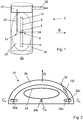
- Fig. 1 shows an NMR magnetic field probe 2 comprising an NMR active substance 4 located in a resonance region 6 within an elongated probe compartment 8 mutually oriented along a longitudinal probe axis A and having a proximal end 10 and a distal end 12.
- the field probe comprises means 14 for pulsed NMR excitation of substance 4 at a probe RF and for receiving an NMR signal generated by substance 4.
- the field probe comprises a substantially cylindrical shield 16 against external high-frequency electromagnetic field irradiation. As shown in Fig. 1 , the shield substantially surrounds the probe compartment 8 and the excitation and receiving means 14.
- the latter comprise an electrically conductive structure comprising a coil member 18 disposed around resonance region 6 and further comprising a pair of connecting leads 20 forming an electrical connection between respective ends of the coil member 18 and an RF coupling unit 22 arranged near proximal end 10.
- the connecting leads 20 are substantially parallel to the longitudinal probe axis A.
- the coil member 18 has a coil axis C which is substantially parallel to the longitudinal probe axis A.
- the RF coupling unit 22 is configured for connecting to an external RF line 32, the latter being connectable to external RF driver and receiver means not shown in the figure.
- the shield 16 has an elongated shape oriented substantially along the longitudinal probe axis (A).
- the elongated probe compartment and conductive structure are disposed within an ellipsoidal jacket 23 having a magnetic susceptibility that is substantially identical to the magnetic susceptibility of the conductive structure.
- the magnetic field probe may further comprise a compensating body arranged e.g. in the region generally indicated as 25.
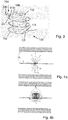
- Fig. 2 shows a coil assembly 24 for MR imaging applications, which comprises a carrier structure 26 made of non-conducting material and further comprises an electrically conducting MR coil 28 for receiving and/or emitting signal at an MR coil operating frequency.
- the MR coil is attached to and extends along a face of the carrier structure 26.
- the coil assembly 24 comprises, in the example shown, three magnetic field probes 30a, 30b, 30c of the type described above.
- the carrier structure 26 has a cap-like hollow shape as might be used for application on a human head, and it has a predefined reference direction R. As seen from Fig. 2 , the probe coil axes Ca, Cb, Cc are all perpendicular to the reference direction R. If the coil assembly 24 is brought into an MR apparatus and oriented such that the reference direction R is parallel to the main magnetic field B of the MR apparatus, all the coil axes Ca, Cb and Cc will be perpendicular to the main magnetic field B.
- the respective RF coupling unit 22c is connected to an RF line 32 which is connectable to external RF driver and receiver means.
- the RF line 32 is provided with a sheath wave barrier 102.
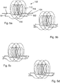
- Fig. 3 shows a sheath wave barrier 102 for suppressing electromagnetic RF coupling phenomena of an electrical cable 104 at a predetermined suppression frequency ( ⁇ 0 ) in a magnetic resonance (MR) imaging or spectroscopy apparatus.
- the cable 104 is a shielded cable with a central conductor 106 and a peripherally surrounding electrically conducting cable sheath 108.
- the sheath wave barrier 102 comprises a segment of the shielded cable, a primary inductor 110 formed from the shielded cable 104 between a first cable location 112 and a second cable location 114, and a secondary inductor 116 formed by a conductor.
- the secondary inductor 116 is made of a simple wire concentrically arranged around the primary inductor 110 and is electrically connected to the cable sheath 108 at said first and second cable connections 112 and 114.
- the secondary inductor is electrically connected to the cable sheath over respective first and second RLC network members.
- both RLC network members are constituted by capacitors C1 and C2, respectively.
- FIG. 5 Various possibilities for the first and second RLC network members are shown in Fig. 5 :
- the carbon fibers were imbued with epoxy resin and the complete layer buildup was cured under pressure to ensure close contact between fibers and dielectric foil.
- a 4 th layer with dielectric foil can be added.
- the layer buildup can be repeated.
- thin copper wires ⁇ 0.2 mm can be added between the fibers.
- the described three-layer structure was compared to a similar, two-layer structure without the dielectric layer (2 crossed unidirectional carbon fiber roving in direct contact). Compared to the two-layer structure, the new three-layer design
- the slight loss in shielding efficiency can be compensated by adding more layers without affecting the properties at audio frequencies.
Landscapes
- Physics & Mathematics (AREA)
- Condensed Matter Physics & Semiconductors (AREA)
- General Physics & Mathematics (AREA)
- High Energy & Nuclear Physics (AREA)
- Health & Medical Sciences (AREA)
- Epidemiology (AREA)
- Magnetic Resonance Imaging Apparatus (AREA)
Priority Applications (2)
| Application Number | Priority Date | Filing Date | Title |
|---|---|---|---|
| EP18192136.2A EP3617729A1 (fr) | 2018-08-31 | 2018-08-31 | Sonde à champ magnétique pour applications d'imagerie par résonance magnétique (irm) |
| PCT/EP2019/065910 WO2019243271A1 (fr) | 2018-06-17 | 2019-06-17 | Sonde de champ magnétique pour des applications d'imagerie par résonance magnétique (irm) |
Applications Claiming Priority (1)
| Application Number | Priority Date | Filing Date | Title |
|---|---|---|---|
| EP18192136.2A EP3617729A1 (fr) | 2018-08-31 | 2018-08-31 | Sonde à champ magnétique pour applications d'imagerie par résonance magnétique (irm) |
Publications (1)
| Publication Number | Publication Date |
|---|---|
| EP3617729A1 true EP3617729A1 (fr) | 2020-03-04 |
Family
ID=63490267
Family Applications (1)
| Application Number | Title | Priority Date | Filing Date |
|---|---|---|---|
| EP18192136.2A Ceased EP3617729A1 (fr) | 2018-06-17 | 2018-08-31 | Sonde à champ magnétique pour applications d'imagerie par résonance magnétique (irm) |
Country Status (1)
| Country | Link |
|---|---|
| EP (1) | EP3617729A1 (fr) |
Citations (9)
| Publication number | Priority date | Publication date | Assignee | Title |
|---|---|---|---|---|
| US4642569A (en) | 1983-12-16 | 1987-02-10 | General Electric Company | Shield for decoupling RF and gradient coils in an NMR apparatus |
| EP1582886A1 (fr) | 2004-04-02 | 2005-10-05 | Universität Zürich | Appareil à résonance magnétique avec des bobines de surveillage de champ magnétique |
| US8190237B2 (en) | 2006-06-12 | 2012-05-29 | Siemens Aktiengesellschaft | MRI adjustable head coil |
| EP2515132A1 (fr) | 2011-04-22 | 2012-10-24 | Eidgenössische Technische Hochschule (ETH) | Agencement de caméra de champ dynamique pour applications de résonnance magnétique et procédés de fonctionnement associés |
| WO2013057643A1 (fr) * | 2011-10-17 | 2013-04-25 | Koninklijke Philips Electronics N.V. | Sonde de champ magnétique pour irm avec un fluoélastomère ou une solution d'un compose fluoré |
| EP2708908A1 (fr) | 2012-09-13 | 2014-03-19 | Skope Magnetic Resonance Technologies GmbH | Isoler des sondes de champ magnétique RM à partir de rayonnement RF externe |
| US9645207B2 (en) | 2011-09-28 | 2017-05-09 | General Electric Company | Adjustable MRI head coil apparatus and MRI system |
| US20170269178A1 (en) * | 2016-03-17 | 2017-09-21 | Samsung Electronics Co., Ltd. | Magnetic field monitoring probe, magnetic resonance imaging apparatus including the same, and method for controlling the same |
| WO2018077679A1 (fr) * | 2016-10-24 | 2018-05-03 | Koninklijke Philips N.V. | Symétriseur destiné à être utilisé dans des systèmes d'imagerie par résonance magnétique (irm) et système d'irm qui utilise le symétriseur |
-
2018
- 2018-08-31 EP EP18192136.2A patent/EP3617729A1/fr not_active Ceased
Patent Citations (9)
| Publication number | Priority date | Publication date | Assignee | Title |
|---|---|---|---|---|
| US4642569A (en) | 1983-12-16 | 1987-02-10 | General Electric Company | Shield for decoupling RF and gradient coils in an NMR apparatus |
| EP1582886A1 (fr) | 2004-04-02 | 2005-10-05 | Universität Zürich | Appareil à résonance magnétique avec des bobines de surveillage de champ magnétique |
| US8190237B2 (en) | 2006-06-12 | 2012-05-29 | Siemens Aktiengesellschaft | MRI adjustable head coil |
| EP2515132A1 (fr) | 2011-04-22 | 2012-10-24 | Eidgenössische Technische Hochschule (ETH) | Agencement de caméra de champ dynamique pour applications de résonnance magnétique et procédés de fonctionnement associés |
| US9645207B2 (en) | 2011-09-28 | 2017-05-09 | General Electric Company | Adjustable MRI head coil apparatus and MRI system |
| WO2013057643A1 (fr) * | 2011-10-17 | 2013-04-25 | Koninklijke Philips Electronics N.V. | Sonde de champ magnétique pour irm avec un fluoélastomère ou une solution d'un compose fluoré |
| EP2708908A1 (fr) | 2012-09-13 | 2014-03-19 | Skope Magnetic Resonance Technologies GmbH | Isoler des sondes de champ magnétique RM à partir de rayonnement RF externe |
| US20170269178A1 (en) * | 2016-03-17 | 2017-09-21 | Samsung Electronics Co., Ltd. | Magnetic field monitoring probe, magnetic resonance imaging apparatus including the same, and method for controlling the same |
| WO2018077679A1 (fr) * | 2016-10-24 | 2018-05-03 | Koninklijke Philips N.V. | Symétriseur destiné à être utilisé dans des systèmes d'imagerie par résonance magnétique (irm) et système d'irm qui utilise le symétriseur |
Non-Patent Citations (2)
| Title |
|---|
| BARMET ET AL., ISMRM, 2009, pages 780 |
| ERIC MICHEL ET AL: "Design of Sample-Immersed Microcoil (SIM) Probes and their Magnetic Field Monitoring Capabilities", PROCEEDINGS OF THE INTERNATIONAL SOCIETY FOR MAGNETIC RESONANCE IN MEDICINE, ISMRM, 23RD ANNUAL MEETING AND EXHIBITION, TORONTO, ONTARIO, CANADA, 30 MAY - 5 JUNE 2015, no. 1839, 15 May 2015 (2015-05-15), pages 1839, XP040667516 * |
Similar Documents
| Publication | Publication Date | Title |
|---|---|---|
| US7205768B2 (en) | Connection lead for an electrical accessory device of an MRI system | |
| US6593744B2 (en) | Multi-channel RF cable trap for magnetic resonance apparatus | |
| US10175318B2 (en) | Isolating MR magnetic field probes from external RF irradiation | |
| CN111279207B (zh) | 用于mr成像的射频线圈的系统 | |
| US20060084861A1 (en) | Magnet and coil configurations for MRI probes | |
| EP1105966B1 (fr) | Appareil d'irm equipe de conducteurs d'alimentation antiparasites pour materiel de connexion electrique | |
| EP2414859B1 (fr) | Dispositifs et câblage destinés à être utilisés dans un système de résonance magnétique à multirésonance | |
| US4680550A (en) | High-frequency antenna device in apparatus for nuclear spin tomography and method for operating this device | |
| EP3807666B1 (fr) | Barrière d'onde de gaine pour applications de résonance magnétique (rm) | |
| EP0304249B1 (fr) | Méthode et appareil pour la résonance magnétique | |
| US6670863B2 (en) | Device for suppressing electromagnetic coupling phenomena | |
| KR101682820B1 (ko) | 자기 공명 단층 촬영에 사용하기 위한 일체형 광학 케이블 가이드를 갖는 시스 전류 필터 | |
| EP3617729A1 (fr) | Sonde à champ magnétique pour applications d'imagerie par résonance magnétique (irm) | |
| US11169232B2 (en) | Device and method for electrically linking electronic assemblies by means of symmetrical shielded cables | |
| WO2019243271A1 (fr) | Sonde de champ magnétique pour des applications d'imagerie par résonance magnétique (irm) | |
| US20190049535A1 (en) | System and method for eliminating shield current from radio frequency (rf) body coil cables in a magnetic resonance imaging (mri) system | |
| EP3617730A1 (fr) | Barrière d'onde de gaine pour applications de résonance magnétique (rm) | |
| WO2011135312A2 (fr) | Détecteur irm |
Legal Events
| Date | Code | Title | Description |
|---|---|---|---|
| PUAI | Public reference made under article 153(3) epc to a published international application that has entered the european phase |
Free format text: ORIGINAL CODE: 0009012 |
|
| AK | Designated contracting states |
Kind code of ref document: A1 Designated state(s): AL AT BE BG CH CY CZ DE DK EE ES FI FR GB GR HR HU IE IS IT LI LT LU LV MC MK MT NL NO PL PT RO RS SE SI SK SM TR |
|
| AX | Request for extension of the european patent |
Extension state: BA ME |
|
| STAA | Information on the status of an ep patent application or granted ep patent |
Free format text: STATUS: THE APPLICATION HAS BEEN REFUSED |
|
| 18R | Application refused |
Effective date: 20200327 |