EP3617796B1 - Vibrationsvorrichtung - Google Patents
Vibrationsvorrichtung Download PDFInfo
- Publication number
- EP3617796B1 EP3617796B1 EP17907986.8A EP17907986A EP3617796B1 EP 3617796 B1 EP3617796 B1 EP 3617796B1 EP 17907986 A EP17907986 A EP 17907986A EP 3617796 B1 EP3617796 B1 EP 3617796B1
- Authority
- EP
- European Patent Office
- Prior art keywords
- cylindrical body
- end portion
- piezoelectric
- vibration device
- piezoelectric element
- Prior art date
- Legal status (The legal status is an assumption and is not a legal conclusion. Google has not performed a legal analysis and makes no representation as to the accuracy of the status listed.)
- Active
Links
Images




Classifications
-
- B—PERFORMING OPERATIONS; TRANSPORTING
- B06—GENERATING OR TRANSMITTING MECHANICAL VIBRATIONS IN GENERAL
- B06B—METHODS OR APPARATUS FOR GENERATING OR TRANSMITTING MECHANICAL VIBRATIONS OF INFRASONIC, SONIC, OR ULTRASONIC FREQUENCY, e.g. FOR PERFORMING MECHANICAL WORK IN GENERAL
- B06B1/00—Methods or apparatus for generating mechanical vibrations of infrasonic, sonic, or ultrasonic frequency
- B06B1/02—Methods or apparatus for generating mechanical vibrations of infrasonic, sonic, or ultrasonic frequency making use of electrical energy
- B06B1/06—Methods or apparatus for generating mechanical vibrations of infrasonic, sonic, or ultrasonic frequency making use of electrical energy operating with piezoelectric effect or with electrostriction
- B06B1/0644—Methods or apparatus for generating mechanical vibrations of infrasonic, sonic, or ultrasonic frequency making use of electrical energy operating with piezoelectric effect or with electrostriction using a single piezoelectric element
- B06B1/0648—Methods or apparatus for generating mechanical vibrations of infrasonic, sonic, or ultrasonic frequency making use of electrical energy operating with piezoelectric effect or with electrostriction using a single piezoelectric element of rectangular shape
-
- G—PHYSICS
- G03—PHOTOGRAPHY; CINEMATOGRAPHY; ANALOGOUS TECHNIQUES USING WAVES OTHER THAN OPTICAL WAVES; ELECTROGRAPHY; HOLOGRAPHY
- G03B—APPARATUS OR ARRANGEMENTS FOR TAKING PHOTOGRAPHS OR FOR PROJECTING OR VIEWING THEM; APPARATUS OR ARRANGEMENTS EMPLOYING ANALOGOUS TECHNIQUES USING WAVES OTHER THAN OPTICAL WAVES; ACCESSORIES THEREFOR
- G03B17/00—Details of cameras or camera bodies; Accessories therefor
- G03B17/02—Bodies
- G03B17/08—Waterproof bodies or housings
-
- B—PERFORMING OPERATIONS; TRANSPORTING
- B06—GENERATING OR TRANSMITTING MECHANICAL VIBRATIONS IN GENERAL
- B06B—METHODS OR APPARATUS FOR GENERATING OR TRANSMITTING MECHANICAL VIBRATIONS OF INFRASONIC, SONIC, OR ULTRASONIC FREQUENCY, e.g. FOR PERFORMING MECHANICAL WORK IN GENERAL
- B06B1/00—Methods or apparatus for generating mechanical vibrations of infrasonic, sonic, or ultrasonic frequency
- B06B1/02—Methods or apparatus for generating mechanical vibrations of infrasonic, sonic, or ultrasonic frequency making use of electrical energy
- B06B1/06—Methods or apparatus for generating mechanical vibrations of infrasonic, sonic, or ultrasonic frequency making use of electrical energy operating with piezoelectric effect or with electrostriction
- B06B1/0607—Methods or apparatus for generating mechanical vibrations of infrasonic, sonic, or ultrasonic frequency making use of electrical energy operating with piezoelectric effect or with electrostriction using multiple elements
- B06B1/0622—Methods or apparatus for generating mechanical vibrations of infrasonic, sonic, or ultrasonic frequency making use of electrical energy operating with piezoelectric effect or with electrostriction using multiple elements on one surface
- B06B1/0625—Annular array
-
- G—PHYSICS
- G02—OPTICS
- G02B—OPTICAL ELEMENTS, SYSTEMS OR APPARATUS
- G02B27/00—Optical systems or apparatus not provided for by any of the groups G02B1/00 - G02B26/00, G02B30/00
- G02B27/0006—Optical systems or apparatus not provided for by any of the groups G02B1/00 - G02B26/00, G02B30/00 with means to keep optical surfaces clean, e.g. by preventing or removing dirt, stains, contamination, condensation
-
- G—PHYSICS
- G02—OPTICS
- G02B—OPTICAL ELEMENTS, SYSTEMS OR APPARATUS
- G02B7/00—Mountings, adjusting means, or light-tight connections, for optical elements
- G02B7/02—Mountings, adjusting means, or light-tight connections, for optical elements for lenses
-
- H—ELECTRICITY
- H04—ELECTRIC COMMUNICATION TECHNIQUE
- H04N—PICTORIAL COMMUNICATION, e.g. TELEVISION
- H04N23/00—Cameras or camera modules comprising electronic image sensors; Control thereof
- H04N23/50—Constructional details
- H04N23/52—Elements optimising image sensor operation, e.g. for electromagnetic interference [EMI] protection or temperature control by heat transfer or cooling elements
-
- H—ELECTRICITY
- H10—SEMICONDUCTOR DEVICES; ELECTRIC SOLID-STATE DEVICES NOT OTHERWISE PROVIDED FOR
- H10N—ELECTRIC SOLID-STATE DEVICES NOT OTHERWISE PROVIDED FOR
- H10N30/00—Piezoelectric or electrostrictive devices
- H10N30/20—Piezoelectric or electrostrictive devices with electrical input and mechanical output, e.g. functioning as actuators or vibrators
- H10N30/208—Piezoelectric or electrostrictive devices with electrical input and mechanical output, e.g. functioning as actuators or vibrators using shear or torsion displacement, e.g. d15 type devices
-
- B—PERFORMING OPERATIONS; TRANSPORTING
- B06—GENERATING OR TRANSMITTING MECHANICAL VIBRATIONS IN GENERAL
- B06B—METHODS OR APPARATUS FOR GENERATING OR TRANSMITTING MECHANICAL VIBRATIONS OF INFRASONIC, SONIC, OR ULTRASONIC FREQUENCY, e.g. FOR PERFORMING MECHANICAL WORK IN GENERAL
- B06B1/00—Methods or apparatus for generating mechanical vibrations of infrasonic, sonic, or ultrasonic frequency
- B06B1/02—Methods or apparatus for generating mechanical vibrations of infrasonic, sonic, or ultrasonic frequency making use of electrical energy
- B06B1/04—Methods or apparatus for generating mechanical vibrations of infrasonic, sonic, or ultrasonic frequency making use of electrical energy operating with electromagnetism
- B06B1/045—Methods or apparatus for generating mechanical vibrations of infrasonic, sonic, or ultrasonic frequency making use of electrical energy operating with electromagnetism using vibrating magnet, armature or coil system
-
- G—PHYSICS
- G03—PHOTOGRAPHY; CINEMATOGRAPHY; ANALOGOUS TECHNIQUES USING WAVES OTHER THAN OPTICAL WAVES; ELECTROGRAPHY; HOLOGRAPHY
- G03B—APPARATUS OR ARRANGEMENTS FOR TAKING PHOTOGRAPHS OR FOR PROJECTING OR VIEWING THEM; APPARATUS OR ARRANGEMENTS EMPLOYING ANALOGOUS TECHNIQUES USING WAVES OTHER THAN OPTICAL WAVES; ACCESSORIES THEREFOR
- G03B2205/00—Adjustment of optical system relative to image or object surface other than for focusing
- G03B2205/0053—Driving means for the movement of one or more optical element
- G03B2205/0061—Driving means for the movement of one or more optical element using piezoelectric actuators
Definitions
- the present invention relates to a vibration device capable of removing water droplets and the like through mechanical vibration.
- Patent Document 1 discloses a camera having a water-droplet-removing function that includes an imaging unit and a vibration unit that vibrates the imaging unit.
- the imaging unit includes a lens and an imaging element that photoelectrically converts light transmitted through the lens.
- the vibration unit vibrates the imaging unit in a direction in which the optical axis of the lens swings and in a direction parallel to the optical axis in order to remove water droplets attached to the lens.
- Patent Document 1 Japanese Unexamined Patent Application Publication No. 2013-080177
- An object of the present invention is to provide a vibration device capable of reliably removing water droplets and the like that are inside the field of view of an imaging device and attached to the surface of a light-transmitting body arranged on the subject side of an imaging element.
- a vibration device includes: a light-transmitting body that is arranged on a subject side of an imaging element; a cylindrical body that has a first end portion, a second end portion on an opposite side from the first end portion, and an outer surface and an inner surface that connect the first end portion and the second end portion to each other, the cylindrical body being connected to the light-transmitting body so as to hold the light-transmitting body on the first end portion side thereof; and a piezoelectric element that is arranged along a circumferential direction of the cylindrical body so as to torsionally vibrate the cylindrical body.
- At least one out of the outer surface and the inner surface has a step portion in a part thereof disposed between a part where the piezoelectric element is arranged and the first end portion in a direction that connects the first end portion and the second end portion of the cylindrical body to each other, and when a distance between the outer surface and the inner surface is regarded as a thickness of the cylindrical body, the thickness decreases via the step portion from a side close to the piezoelectric element toward a side close to the first end portion.
- the displacement of the light-transmitting body realized by the torsional vibration of the cylindrical body can be further increased. Therefore, water droplets and the like attached to the surface of the light-transmitting body inside the field of view of the imaging device can be more reliably removed.
- the outer surface of the cylindrical body has the step portion, and a part of the outer surface that is continuous with the step portion and extends toward the first end portion is more inwardly located than a part of the outer surface that is continuous with the step portion and extends toward the piezoelectric element.
- the vibration device can be reduced in size.
- At least one out of the outer surface and the inner surface has an inclined portion that extends so as to be inclined with respect to the direction that connects the first end portion and the second end portion of the cylindrical body to each other in a part of the cylindrical body located between the part where the piezoelectric element is arranged and the first end portion in the direction that connects the first end portion and the second end portion of the cylindrical body to each other, and when a distance between the outer surface and the inner surface is regarded as a thickness of the cylindrical body, the inclined portion is provided so that the thickness decreases from a side close to the piezoelectric element toward a side close to the first end portion.
- water droplets and the like attached to the surface of the light-transmitting body inside the field of view of the imaging device can be more reliably removed.
- the outer surface of the cylindrical body has the inclined portion, and the inclined portion extends from the side close to the piezoelectric element toward the side close to the first end portion and toward an interior of the cylindrical body.
- the vibration device can be reduced in size.
- the piezoelectric element is arranged between the first end portion and the second end portion of the cylindrical body.
- the piezoelectric element is arranged at a position of a node of a torsional vibration of the cylindrical body. In this case, the piezoelectric element is not liable to deform and is not liable to be damaged.
- a plurality of the piezoelectric elements are provided, the plurality of piezoelectric elements are arranged in an annular shape along a circumferential direction of the cylindrical body so as to be spaced apart from each other, the plurality of piezoelectric elements each include a piezoelectric body, and the plurality of piezoelectric bodies are polarized so as to follow the circumferential direction of the cylindrical body.
- the piezoelectric element includes a ring-shaped piezoelectric body, the ring-shaped piezoelectric body has a first main surface that is located on a side close to the first end portion of the cylindrical body and a second main surface that is located on a side close to the second end portion of the cylindrical body, the ring-shaped piezoelectric body is divided into a plurality of regions along the circumferential direction of the cylindrical body and the ring-shaped piezoelectric body is polarized so as to follow the circumferential direction of the cylindrical body in the plurality of regions, and excitation electrodes are provided on the first main surface and the second main surface so as to cover the plurality of regions.
- the ring-shaped piezoelectric body is divided into at least six regions.
- the vibration device further includes a piezoelectric vibrator that is a piezoelectric element other than the piezoelectric element, and the piezoelectric vibrator has a vibration mode that is one out of a vibration mode in which the piezoelectric vibrator vibrates the cylindrical body in a direction that connects the inner surface and the outer surface to each other and a vibration mode in which the piezoelectric vibrator vibrates the cylindrical body in a direction that connects the first end portion and the second end portion to each other.
- a piezoelectric vibrator that is a piezoelectric element other than the piezoelectric element
- the piezoelectric vibrator has a vibration mode that is one out of a vibration mode in which the piezoelectric vibrator vibrates the cylindrical body in a direction that connects the inner surface and the outer surface to each other and a vibration mode in which the piezoelectric vibrator vibrates the cylindrical body in a direction that connects the first end portion and the second end portion to each other.
- a vibration device capable of reliably removing water droplets and the like that are inside the field of view of an imaging device and attached to the surface of a light-transmitting body disposed on the subject side of an imaging element.
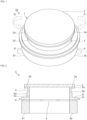
- Fig. 1 is a perspective view of a vibration device according to a first embodiment of the present invention.
- Fig. 2 is a front sectional view of the vibration device according to the first embodiment.
- Fig. 3 is a front sectional view of an imaging device that includes the vibration device of the first embodiment.
- a vibration device 1 includes a light-transmitting body 2.
- the light-transmitting body 2 is arranged on a subject side of an imaging element 9, that is, in front of the imaging element 9.
- the imaging element 9 include a CMOS, a CCD, a bolometer, a thermopile, and the like that receive light of any wavelength from the visible region to the far infrared region.
- Possible examples of the imaging device 10 include a camera, radar and LIDAR devices, and so on.
- the light-transmitting body 2 is composed of a light-transmitting material.
- a light-transmitting plastic, glass, or a light-transmitting ceramic can be used as the light-transmitting material.
- the light-transmitting body 2 has a disk shape.
- the shape of the light-transmitting body 2 is not limited to this example, and for example may instead have a dome shape.
- a cylindrical body 3 is connected to the light-transmitting body 2.
- the cylindrical body 3 includes a first end portion 3a, a second end portion 3b that is on the opposite side from the first end portion 3a, and an outer surface 3d and an inner surface 3e that connect the first end portion 3a and the second end portion 3b to each other.
- the inner surface 3e is shaped so as to face the side surface of the cylinder, and the direction connecting the inner surface 3e and the outer surface 3d to each other is the radial direction of the cylindrical body 3.
- the direction connecting the first end portion 3a and the second end portion 3b to each other is the axial direction of the cylindrical body 3.
- a plurality of piezoelectric elements 4 are provided between the first end portion 3a and the second end portion 3b of the cylindrical body 3. More specifically, the cylindrical body 3 includes a first cylindrical body part 3X that includes the first end portion 3a and a second cylindrical body part 3Y that includes the second end portion 3b, and the plurality of piezoelectric elements 4 are provided between the first cylindrical body part 3X and the second cylindrical body part 3Y.
- the cylindrical body 3 is a cylindrical body formed by integrating the first cylindrical body part 3X and the second cylindrical body part 3Y with each other with the piezoelectric elements 4 interposed therebetween.
- the cylindrical body 3 may instead be composed of one cylindrical body. In this case, for example, grooves may be provided in the cylindrical body 3 and the piezoelectric elements 4 may be arranged in the grooves.
- the piezoelectric elements 4 may be provided at a step portion or the like provided in the cylindrical body 3.
- the first end portion 3a is connected to the light-transmitting body 2. More specifically, the cylindrical body 3 has a support portion 3A that includes the first end portion 3a.
- the support portion 3A of the cylindrical body 3 is fixed to a peripheral portion of the surface of the light-transmitting body 2 on the cylindrical body 3 side so that an opening of the cylindrical body 3 on the first end portion 3a side is closed by the light-transmitting body 2.
- the support portion 3A may instead be fixed to a part of the surface of the light-transmitting body 2 on the cylindrical body 3 side that is further toward the inside than the peripheral portion.
- the cylindrical body 3 is composed of stainless steel in this embodiment.
- another metal material may be used instead of stainless steel.
- a metal that is an elastic material having high rigidity such as stainless steel is desirable.
- the cylindrical body 3 may be composed of a composite body including a resin and a material having a higher rigidity than the resin, or may be composed of glass.
- a hinge portion 3c which extends outward in the radial direction of the cylindrical body 3, is provided on the outer surface 3d of the cylindrical body 3.
- the hinge portion 3c is used to support the vibration device 1 from the outside.
- the plurality of piezoelectric elements 4 are provided close to the hinge portion 3c in the axial direction of the cylindrical body 3. The positional relationship between the hinge portion 3c and the piezoelectric elements 4 is not limited to this example.
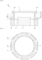
- Fig. 4 is a plan sectional view of the vibration device illustrating the arrangement of the piezoelectric elements in the first embodiment.
- the plurality of piezoelectric elements 4 are arranged in an annular shape along a circumferential direction of the cylindrical body 3.
- the plurality of piezoelectric elements 4 are arranged so as to be spaced apart from each other.
- the plurality of piezoelectric elements 4 each include a piezoelectric body 5.
- the shape of the piezoelectric body 5 is not particularly limited, and is a rectangular parallelepiped shape in this embodiment.
- Arrows P in Fig. 4 indicate the polarization directions of the piezoelectric bodies 5.
- the piezoelectric bodies 5 are polarized along the circumferential direction. More specifically, the plurality of piezoelectric bodies 5 are polarized so as to follow the circumferential direction.
- each piezoelectric body 5 has a first main surface and a second main surface that are located on the first end portion side and the second end portion side of the cylindrical body 3 and face each other. Excitation electrodes are provided on the first main surface and the second main surface. An alternating-current voltage is applied to the excitation electrodes.
- the piezoelectric elements 4 of this embodiment are shear mode piezoelectric elements that undergo sliding deformation in response to application of a voltage. When an alternating-current voltage is applied to the plurality of piezoelectric elements 4 arranged along the circumferential direction of the cylindrical body 3, the cylindrical body 3 torsionally vibrates as indicated by arrows R in Fig. 1 .
- the plurality of piezoelectric elements 4 are arranged at the position of a node of the torsional vibration of the cylindrical body 3.
- the outer surface 3d of the cylindrical body 3 has a first step portion 3f and a second step portion 3g.
- the first step portion 3f and the second step portion 3g extend in the radial direction of the cylindrical body 3 and extend along the circumferential direction of the cylindrical body 3.
- the first step portion 3f and the second step portion 3g are located between a part where the piezoelectric elements 4 are arranged and the first end portion 3a in the axial direction of the cylindrical body 3.
- the first step portion 3f is located closer to the piezoelectric elements 4 than the second step portion 3g.
- the distance between the outer surface 3d and the inner surface 3e is taken to be the thickness of the cylindrical body 3.
- the thickness of the cylindrical body 3 changes via the first step portion 3f and the second step portion 3g. More specifically, the thickness decreases from the side close to the piezoelectric elements 4 toward the first end portion 3a via the first step portion 3f. Similarly, the thickness decreases from the side close to the first step portion 3f toward the first end portion 3a via the second step portion 3g. Thus, the thickness of the cylindrical body 3 decreases in two steps between the piezoelectric elements 4 and the first end portion 3a.
- the number of places where a step portion is provided in the cylindrical body 3 is not particularly limited. Alternatively, step portions do not have to be provided in the cylindrical body 3.
- the thickness of the support portion 3A of the cylindrical body 3 is larger than the thickness of the part of the cylindrical body 3 located between the support portion 3A and the second step portion 3g.
- the light-transmitting body 2 can be suitably fixed to the cylindrical body 3.
- the thickness of the support portion 3A may instead be the same as the thickness of the part of the cylindrical body 3 located between the second step portion 3g and the support portion 3A.
- the part of the outer surface 3d that is continuous with the first step portion 3f and extends toward the first end portion 3a is located closer to the inside than the part of the outer surface 3d that is continuous with the first step portion 3f and extends toward the piezoelectric elements 4.
- the part of the outer surface 3d that is continuous with the second step portion 3g and extends toward the first end portion 3a is located closer to the inside than the part of the outer surface 3d that is continuous with the second step portion 3g and extends toward the piezoelectric elements 4. In this way, the vibration device 1 can be reduced in size.
- the vibration device 1 includes a plurality of piezoelectric elements 4 that are arranged along the circumferential direction of the cylindrical body 3 so as to torsionally vibrate the cylindrical body 3.
- the light-transmitting body 2, which is bonded to the cylindrical body 3, rotates as a result of the cylindrical body 3 torsionally vibrating.
- a centrifugal force acts on water droplets and foreign matter attached to the surface of the light-transmitting body 2.
- a force acting toward the space outside the field of view of the imaging device 10 is reliably applied to the water droplets and foreign matter. Therefore, water droplets and foreign matter inside the field of view of the imaging device 10 can be reliably removed.
- the thickness of the cylindrical body 3 becomes smaller toward first end portion 3a as a result of the cylindrical body 3 having the first step portion 3f and the second step portion 3g. Consequently, torsional vibration displacement of the first end portion 3a can be made even larger and displacement of the light-transmitting body 2 in the circumferential direction can be made even larger. Therefore, the centrifugal force acting on water droplets and foreign matter attached to the surface of the light-transmitting body 2 can be made even larger and the water droplets and foreign matter inside the field of view of the imaging device 10 can be removed even more reliably.
- the number of places where a step portion is provided in the cylindrical body 3 is not particularly limited, and for example, a step portion may be provided in one place.
- Fig. 5 is a front sectional view of a vibration device according to a first modification of the first embodiment.
- one step portion 103f is provided on an outer surface 103d of a cylindrical body 103.
- the thickness of the part of the cylindrical body 103 that is closer to a first end portion 103a than the step portion 103f is the same as the thickness of the part of the cylindrical body 3 of the first embodiment illustrated in Fig. 3 located between the first step portion 3f and the second step portion 3g.
- Fig. 6 is a front sectional view of a vibration device according to a second modification of the first embodiment.
- a step portion 113f is provided on an inner surface 113e of a cylindrical body 113.
- the piezoelectric elements 4 are provided closer to a second end portion 113b than in the first embodiment and the first modification.
- Displacements of the torsional vibrations of the vibration devices of the first embodiment, the first modification, and the second modification were evaluated.
- the dimension of the cylindrical body along the axial direction was taken to be the height of the cylindrical body.
- a value obtained by dividing the displacement of the light-transmitting body in the circumferential direction by the displacement of the second end portion of the cylindrical body in the circumferential direction was taken to be an amplification ratio.
- the specifications of the cylindrical body of first embodiment were as follows.
- the specifications of the cylindrical body of the first modification were as follows.
- the amplification ratio was 1486 nm/282 nm.
- the amplification ratio was 960 nm/288 nm.
- the amplification ratio was 902 nm/460 nm.
- the thickness of the cylindrical body 3 decreases via the first step portion 3f and the second step portion 3g, and as a result the part of the cylindrical body 3 having a small thickness has a small dimension along the axial direction. Therefore, in the first embodiment, a decrease in strength is less likely to occur and the amplification ratio can be further increased.
- Fig. 7 is a front sectional view of a vibration device according to a third modification of the first embodiment.
- a cylindrical body 123 is formed as an integrated body and the plurality of piezoelectric elements 4 are arranged on a second end portion 123b.
- the position at which the plurality of piezoelectric elements 4 are arranged in the axial direction of the cylindrical body 123 is not particularly limited.
- the plurality of piezoelectric elements 4 be arranged at the position of a node of the torsional vibration of the cylindrical body 3 as in the first embodiment illustrated in Fig. 3 .
- the piezoelectric elements 4 are not liable to deform and are not liable to be damaged.
- the hinge portion 3c is disposed close to the piezoelectric elements 4 and is provided close to the position of a node, and therefore the torsional vibration is not likely to be attenuated even when the vibration device 1 is supported from the outside.
- Fig. 8 is a front sectional view of a vibration device according to a fourth modification of the first embodiment.
- an outer surface 133d of a cylindrical body 133 includes a first inclined portion 133f and a second inclined portion 133g that extend so as to be inclined with respect to the axial direction of the cylindrical body 133.
- the first inclined portion 133f is provided so that the thickness thereof decreases from the side close to the piezoelectric elements 4 toward the side close to a first end portion 133a.
- the first inclined portion 133f extends from the side close to the piezoelectric elements 4 toward the side close to the first end portion 133a and extends toward the inside of the cylindrical body 133.
- the first inclined portion 133f extends along the circumferential direction of the cylindrical body 133.
- the second inclined portion 133g is similarly configured.
- the number of places where an inclined portion is provided in the cylindrical body 133 is not particularly limited.
- An inclined portion may be provided on an inner surface 133e.
- Fig. 9 is a plan view illustrating piezoelectric elements in a second embodiment.
- a piezoelectric element 24 includes a ring-shaped piezoelectric body 25.
- the rest of the configuration of the vibration device of this embodiment is the same as that of the vibration device 1 of the first embodiment.
- the ring-shaped piezoelectric body 25 has a first main surface 25a and a second main surface 25b, which face each other.
- the first main surface 2.5a is positioned on a side close to the first end portion of the cylindrical body and the second main surface 25b is positioned on a side close to the second end portion of the cylindrical body.
- the ring-shaped piezoelectric body 25 is divided into a plurality of regions along the circumferential direction of the cylindrical body. Single dot chain lines in Fig. 9 represent the boundaries between the plurality of regions. In this embodiment, the ring-shaped piezoelectric body 25 is divided into six regions.
- the ring-shaped piezoelectric body 25 is polarized so as to follow the circumferential direction of the cylindrical body in the plurality of regions.
- Excitation electrodes 26 are provided on the first main surface 25a and the second main surface 25b so as to cover the plurality of regions.
- the cylindrical body torsionally vibrates as a result of an alternating-current voltage being applied to the excitation electrodes 26 of the piezoelectric element 24. Therefore, similarly to the first embodiment, water droplets and foreign matter attached to the surface of the light-transmitting body inside the field of view of the imaging device can be more reliably removed.
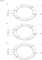
- Figs. 10(a) to 10(c) are perspective views for describing a method of manufacturing the ring-shaped piezoelectric body in the second embodiment.
- Fig. 11 is a schematic front sectional view for describing a method of manufacturing the ring-shaped piezoelectric body in the second embodiment.
- the symbols in Figs. 10(a) to 10(c) and Fig. 11 indicate the signs of electric fields applied by polarization electrodes, which are described later.
- a ring-shaped piezoelectric body 27 having a first main surface 27a and a second main surface 27b that face each other is prepared.
- a plurality of polarization electrodes 28 are uniformly provided along the circumferential direction of the ring-shaped piezoelectric body 27 on the first main surface 27a of the ring-shaped piezoelectric body 27.
- a plurality of polarization electrodes 28 are provided on the second main surface 27b so as to face the polarization electrodes 28 on the first main surface 27a.
- the ring-shaped piezoelectric body 27 is divided into a plurality of regions.
- a poling treatment is simultaneously performed using the polarization electrodes 28 on a pair of regions of the ring-shaped piezoelectric body 27 that are maximally separated from each other.
- polarization electrodes 28 that face each other in the thickness direction of the ring-shaped piezoelectric body 27 have the same sign and an electric field is applied in the circumferential direction of the regions.
- a poling treatment is performed on another pair of maximally separated regions that are different from the regions polarized in the step illustrated in Fig. 10(a) .
- a poling treatment is performed on another pair of maximally separated regions that are different from the regions polarized in the steps illustrated in Figs. 10(a) and 10(b) .
- the ring-shaped piezoelectric body 25 illustrated in Fig. 9 can be obtained.
- the poling treatment be simultaneously performed on a pair of regions. Consequently, the total number of times the poling treatment has to be performed can be reduced and productivity can be increased.
- the regions on which the poling treatment is simultaneously performed are close to each other, there is a risk of a region interposed between the regions on which the poling treatment is being simultaneously performed being polarized in the opposite direction.
- the ring-shaped piezoelectric body 27 illustrated in Figs. 10(a) to 10(c) is preferably divided into at least six regions. Therefore, the distance between the regions on which the poling treatment is to be simultaneously performed can be effectively increased. Therefore, the situation in which a region interposed between the regions on which the poling treatment is being simultaneously performed becomes polarized in the opposite direction can be more reliably suppressed.
- Fig. 12 is a front sectional view of a vibration device according to a third embodiment.
- This embodiment differs from the first embodiment in that this embodiment includes a piezoelectric vibrator 34, which is a piezoelectric element other than the piezoelectric elements 4.
- the rest of the configuration of the vibration device of the third embodiment is the same as that of the vibration device 1 of the first embodiment.
- the piezoelectric vibrator 34 includes a ring-shaped piezoelectric body 35.
- the ring-shaped piezoelectric body 35 is polarized parallel to the axial direction of the cylindrical body 3.
- the ring-shaped piezoelectric body 35 has a first main surface that is located on the first end portion 3a side of the cylindrical body 3 and a second main surface that is located on the second end portion 3b side of the cylindrical body 3.
- excitation electrodes are provided on the first main surface and the second main surface.
- a respiratory vibration which is a vibration mode in which the cylindrical body 3 is vibrated in the radial direction, is excited by applying an alternating-current voltage to the excitation electrodes of the piezoelectric vibration body 34.
- the light-transmitting body 2 undergoes bending vibration in response to the cylindrical body 3 undergoing respiratory vibration.
- the piezoelectric vibrator 34 may instead be a piezoelectric vibrator in which a vertical vibration, which is a vibration mode in which the cylindrical body 3 is vibrated in the axial direction, is excited by applying an alternating-current voltage to the excitation electrodes.
- the light-transmitting body 2 also undergoes bending vibration in the case where the cylindrical body 3 undergoing vertical vibration.
- this vibration mode can be expressed as an (m, n) mode.
- m and n are integers.
- m is the number of vibration nodes that are present in the radial direction of the disk and n is the number of nodes that are present in the circumferential direction of the disk.
- Fig. 13(a) illustrates a (0, 0) mode vibration
- Fig. 13(b) illustrates a (1, 0) mode
- Fig. 13(c) illustrates a (0, 1) mode
- Fig. 13(d) illustrates a (0, 2) mode.
- Figs. 13(a) to 13(d) points B1, B2, B3, B4, and B5 to B8 shaded with hatching indicate the points of maximum displacement.
- regions shaded with diagonal hatching and the white parts indicate parts that fluctuate with opposite phases. Therefore, in Fig. 13(b) , a circle C1 is a vibration node, the circle C1 is a singular node that exists in the radial direction and there are no nodes in the circumferential direction. Therefore, the vibration mode in Fig. 13(b) can be expressed as a (1, 0) mode.
- the light-transmitting body 2 is vibrated in a (0, 0) mode or a (1, 0) mode.
- a large displacement is generated in the vicinity of a point of maximum displacement and the attached water droplets can be atomized.
- this embodiment includes the piezoelectric elements 4 and the piezoelectric vibrator 34.
- Water droplets and foreign matter inside the field of view of the imaging device can be more reliably removed by switching between the torsional vibration generated by the piezoelectric elements 4 and the vibration mode generated by the piezoelectric vibrator 34.
- water droplets and foreign matter are moved to the outside of the light-transmitting body 2 by the torsional vibration generated by the piezoelectric elements 4 and the moved water droplets and foreign matter are then removed through the vibration mode generated by the piezoelectric vibrator 34.
- this embodiment is particularly suitable for imaging device having a wide field of view.
Landscapes
- Physics & Mathematics (AREA)
- Engineering & Computer Science (AREA)
- General Physics & Mathematics (AREA)
- Mechanical Engineering (AREA)
- Optics & Photonics (AREA)
- Multimedia (AREA)
- Electromagnetism (AREA)
- Signal Processing (AREA)
- Camera Bodies And Camera Details Or Accessories (AREA)
- General Electrical Machinery Utilizing Piezoelectricity, Electrostriction Or Magnetostriction (AREA)
- Studio Devices (AREA)
- Structure And Mechanism Of Cameras (AREA)
- Accessories Of Cameras (AREA)
- Apparatuses For Generation Of Mechanical Vibrations (AREA)
Claims (11)
- Eine Vibrationsvorrichtung (1), die folgende Merkmale aufweist:einen lichtdurchlässigen Körper (2), der auf einer Subjektseite eines Bilderzeugungselements (9) angeordnet ist;einen Zylinderkörper (3, 103, 113, 123, 133), der einen ersten Endabschnitt (3a, 103a, 133a), einen zweiten Endabschnitt (3b, 113b, 123b) an einer dem ersten Endabschnitt (3a, 103a, 133a) gegenüberliegenden Seite sowie eine Außenfläche (3d, 103d, 133d) und eine Innenfläche (3e, 113e, 133e) aufweist, die den ersten Endabschnitt (3a, 103a, 133a) und den zweiten Endabschnitt (3b, 113b, 123b) miteinander verbinden, wobei der Zylinderkörper (3, 103, 113, 123, 133) mit dem lichtdurchlässigen Körper (2) zum Halten des lichtdurchlässigen Körpers (2) an dem ersten Endabschnitt desselben verbunden ist; undein piezoelektrisches Element (4, 24);dadurch gekennzeichnet, dassdas piezoelektrische Element (4, 24) zum torsionsmäßigen Vibrieren des Zylinderkörpers (3, 103, 113, 123, 133) entlang einer Umfangsrichtung des Zylinderkörpers (3, 103, 113, 123, 133) angeordnet ist.
- Die Vibrationsvorrichtung (1) gemäß Anspruch 1,bei der zumindest eine von der Außenfläche (3d, 103d, 133d) und der Innenfläche (3e, 113e, 133e) einen Stufenabschnitt (3f, 113f, 133f) in einem Teil des Zylinderkörpers (3, 103, 113, 123, 133) aufweist, der zwischen einem Teil, an dem das piezoelektrische Element (4) angeordnet ist, und dem ersten Endabschnitt (3a, 103a, 133a) angebracht ist, in einer Richtung, die den ersten Endabschnitt (3a, 103a, 133a) und den zweiten Endabschnitt (3b, 113b, 123b) des Zylinderkörpers (3, 103, 113, 123, 133) miteinander verbindet, undsich die Dicke über den Stufenabschnitt (3f, 113f, 133f) von einer Seite nahe dem piezoelektrischen Element (4) hin zu einer Seite nahe dem ersten Endabschnitt (3a, 103a, 133a) verringert, wenn ein Abstand zwischen der Außenfläche (3d, 103d, 133d) und der Innenfläche (3e, 113e, 133e) als eine Dicke des Zylinderkörpers (3, 103, 113, 123, 133) angesehen wird.
- Die Vibrationsvorrichtung (1) gemäß Anspruch 1,bei der die Außenfläche (3d, 103d, 133d) des Zylinderkörpers (3, 103, 113, 123, 133) den Stufenabschnitt (3f, 133f) aufweist, undsich ein Teil der Außenfläche (3d, 103d, 133d), der durchgehend mit dem Stufenabschnitt ist und sich zum ersten Endabschnitt (3a, 103a, 133a) hin erstreckt, weiter innen befindet als ein Teil der Außenfläche (3d, 103d, 133d), der durchgehend mit dem Stufenabschnitt ist und sich zu dem piezoelektrischen Element (4) hin erstreckt.
- Die Vibrationsvorrichtung (1) gemäß Anspruch 1,bei der zumindest eine von der Außenfläche (133d) und der Innenfläche (133e) einen geneigten Abschnitt (133f, 133g) aufweist, der sich so erstreckt, dass er bezüglich der Richtung, die den ersten Endabschnitt (133a) und den zweiten Endabschnitt des Zylinderkörpers (133) verbindet, geneigt ist, in einem Teil, der sich zwischen dem Teil, an dem das piezoelektrische Element (4) angeordnet ist, und dem ersten Endabschnitt (133a) befindet, in der Richtung, die den ersten Endabschnitt (133a) und den zweiten Endabschnitt des Zylinderkörpers (133) verbindet, undder geneigte Abschnitt (133f, 133g) derart vorgesehen ist, dass sich die Dicke von einer Seite nahe dem piezoelektrischen Element (4) hin zu einer Seite nahe dem ersten Endabschnitt (133a) verringert, wenn ein Abstand zwischen der Außenfläche (133d) und der Innenfläche (133e) als eine Dicke des Zylinderkörpers (133) angesehen wird.
- Die Vibrationsvorrichtung (1) gemäß Anspruch 4,bei der die Außenfläche (133d) des Zylinderkörpers (133) den geneigten Abschnitt (133f, 133g) aufweist, undsich der geneigte Abschnitt (133f, 133g) von der Seite nahe dem piezoelektrischen Element (4) hin zu der Seite nahe dem ersten Endabschnitt (133a) und hin zu einem Innenraum des Zylinderkörpers (133) erstreckt.
- Die Vibrationsvorrichtung (1) gemäß einem der Ansprüche 1 bis 5,
bei der das piezoelektrische Element (4) zwischen dem ersten Endabschnitt (3a, 103a, 133a) und dem zweiten Endabschnitt (3b, 113b, 123b) des Zylinderkörpers (3, 103, 113, 123, 133) angeordnet ist. - Die Vibrationsvorrichtung (1) gemäß einem der Ansprüche 1 bis 6,
bei der das piezoelektrische Element (4) an einer Position eines Knotens einer Torsionsvibration des Zylinderkörpers (3, 103, 113, 123, 133) angeordnet ist. - Die Vibrationsvorrichtung (1) gemäß einem der Ansprüche 1 bis 7,bei der eine Mehrzahl der piezoelektrischen Elemente (4, 24) vorgesehen sind,die Mehrzahl von piezoelektrischen Elementen (4, 24) ringförmig derart entlang einer Umfangsrichtung des Zylinderkörpers (3, 103, 113, 123, 133) angeordnet sind, dass sie voneinander beabstandet sind, unddie Mehrzahl von piezoelektrischen Elementen (4) jeweils einen piezoelektrischen Körper (5, 25, 27, 35) umfasst und die Mehrzahl von piezoelektrischen Körpern (5, 25, 27, 35) der Umfangsrichtung des Zylinderkörpers (3, 103, 113, 123, 133) folgend polarisiert sind.
- Die Vibrationsvorrichtung (1) gemäß einem der Ansprüche 1 bis 7,bei der das piezoelektrische Element (24) einen ringförmigen piezoelektrischen Körper (25, 27, 35) umfasst,der ringförmige piezoelektrische Körper (25, 27, 35) eine erste Hauptfläche (25a, 27a), die sich an einer Seite nahe dem ersten Endabschnitt (3a, 103a, 133a) des Zylinderkörpers (3, 103, 113, 123, 133) befindet, und eine zweite Hauptfläche (25b, 27b) aufweist, die sich an einer Seite nahe dem zweiten Endabschnitt (3b, 113b, 123b) des Zylinderkörpers (3, 103, 113, 123, 133) befindet,der ringförmige piezoelektrische Körper (25, 27, 35) entlang der Umfangsrichtung des Zylinderkörpers (3, 103, 113, 123, 133) in eine Mehrzahl von Bereichen unterteilt ist und der ringförmige piezoelektrische Körper (25, 27, 35) der Umfangsrichtung des Zylinderkörpers (3, 103, 113, 123, 133) in der Mehrzahl von Bereichen folgend polarisiert ist, undErregungselektroden (26, 28) auf der ersten Hauptfläche (25a, 27a) und der zweiten Hauptfläche (25b, 27b) vorgesehen sind, um die Mehrzahl von Bereichen abzudecken.
- Die Vibrationsvorrichtung (1) gemäß Anspruch 9,
bei der der ringförmige piezoelektrische Körper (25, 27, 35) in zumindest sechs Bereiche unterteilt ist. - Die Vibrationsvorrichtung (1) gemäß einem der Ansprüche 1 bis 10, die ferner folgende Merkmale aufweist:ein piezoelektrisches Vibrationselement (34), das ein piezoelektrisches Element ist, das nicht das piezoelektrische Element (4, 24) ist;wobei das piezoelektrische Vibrationselement (34) einen Vibrationsmodus aufweist, der einer von einem Vibrationsmodus, bei dem das piezoelektrische Vibrationselement (34) den Zylinderkörper (3, 103, 113, 123, 133) in einer Richtung vibrieren lässt, die die Innenfläche (3e, 113e, 133e) und die Außenfläche (3d, 103d, 133d) miteinander verbindet, und einem Vibrationsmodus ist, bei dem das piezoelektrische Vibrationselement (34) den Zylinderkörper (3, 103, 113, 123, 133) in einer Richtung vibrieren lässt, die den ersten Endabschnitt (3a, 103a, 133a) und den zweiten Endabschnitt (3b, 113b, 123b) miteinander verbindet.
Applications Claiming Priority (2)
| Application Number | Priority Date | Filing Date | Title |
|---|---|---|---|
| JP2017089410 | 2017-04-28 | ||
| PCT/JP2017/044348 WO2018198417A1 (ja) | 2017-04-28 | 2017-12-11 | 振動装置 |
Publications (3)
| Publication Number | Publication Date |
|---|---|
| EP3617796A1 EP3617796A1 (de) | 2020-03-04 |
| EP3617796A4 EP3617796A4 (de) | 2021-01-06 |
| EP3617796B1 true EP3617796B1 (de) | 2023-10-18 |
Family
ID=63919574
Family Applications (1)
| Application Number | Title | Priority Date | Filing Date |
|---|---|---|---|
| EP17907986.8A Active EP3617796B1 (de) | 2017-04-28 | 2017-12-11 | Vibrationsvorrichtung |
Country Status (5)
| Country | Link |
|---|---|
| US (1) | US11504742B2 (de) |
| EP (1) | EP3617796B1 (de) |
| JP (1) | JP6610836B2 (de) |
| CN (1) | CN110573960B (de) |
| WO (1) | WO2018198417A1 (de) |
Families Citing this family (11)
| Publication number | Priority date | Publication date | Assignee | Title |
|---|---|---|---|---|
| WO2018100796A1 (ja) * | 2016-11-30 | 2018-06-07 | 株式会社村田製作所 | 振動装置、カメラ用水滴除去装置及びカメラ |
| EP3668079B1 (de) * | 2017-12-27 | 2022-09-28 | Murata Manufacturing Co., Ltd. | Vibrationsvorrichtung und optische detektionsvorrichtung |
| WO2020003572A1 (ja) * | 2018-06-28 | 2020-01-02 | 株式会社村田製作所 | 振動装置及び光学検出装置 |
| TWI686226B (zh) * | 2018-11-22 | 2020-03-01 | 國立臺灣大學 | 超音波細胞刺激裝置 |
| JP6819846B1 (ja) * | 2019-11-22 | 2021-01-27 | 株式会社村田製作所 | 振動装置、および振動装置を備える撮像ユニット |
| WO2021100227A1 (ja) * | 2019-11-22 | 2021-05-27 | 株式会社村田製作所 | 振動装置、および振動装置を備える撮像ユニット |
| JP6819845B1 (ja) * | 2019-11-22 | 2021-01-27 | 株式会社村田製作所 | 振動装置、および振動装置を備える撮像ユニット |
| WO2021111668A1 (ja) * | 2019-12-06 | 2021-06-10 | 株式会社村田製作所 | 振動装置及び撮像装置 |
| JP7111258B2 (ja) * | 2020-03-27 | 2022-08-02 | 株式会社村田製作所 | 振動装置及び振動制御方法 |
| JP7556473B2 (ja) * | 2021-08-18 | 2024-09-26 | 株式会社村田製作所 | 筐体およびセンサ装置 |
| WO2023095366A1 (ja) * | 2021-11-26 | 2023-06-01 | 株式会社村田製作所 | 振動装置および撮像装置 |
Family Cites Families (25)
| Publication number | Priority date | Publication date | Assignee | Title |
|---|---|---|---|---|
| US7324149B2 (en) | 2002-05-20 | 2008-01-29 | Olympus Optical Co., Ltd. | Camera and image pick-up device unit having an optical member that is vibrated to remove dust |
| JP2004064554A (ja) * | 2002-07-30 | 2004-02-26 | Olympus Corp | カメラ及びこれに用いる撮像素子ユニット |
| ATE489734T1 (de) | 2005-05-26 | 2010-12-15 | Nikon Corp | Vibrierender aktuator und methode zum betreiben eines vibrierenden aktuators |
| JP4835042B2 (ja) * | 2005-05-30 | 2011-12-14 | 株式会社ニコン | 振動波モータ |
| JP4871594B2 (ja) * | 2006-01-12 | 2012-02-08 | キヤノン株式会社 | 振動波駆動装置及び振動波駆動機器 |
| JP4888569B2 (ja) * | 2008-05-27 | 2012-02-29 | 株式会社村田製作所 | 超音波モータ |
| JP2010181584A (ja) * | 2009-02-05 | 2010-08-19 | Olympus Imaging Corp | レンズ鏡筒、カメラ、およびカメラシステム |
| JP4790056B2 (ja) * | 2009-03-11 | 2011-10-12 | オリンパスイメージング株式会社 | 振動装置及びそれを用いた画像機器 |
| JP5439272B2 (ja) * | 2010-04-26 | 2014-03-12 | オリンパスイメージング株式会社 | 振動装置及びそれを用いた画像機器 |
| JP5675265B2 (ja) * | 2010-10-20 | 2015-02-25 | オリンパスイメージング株式会社 | 振動装置及びそれを用いた画像機器 |
| WO2012129521A1 (en) * | 2011-03-23 | 2012-09-27 | Gentex Corporation | Lens cleaning apparatus |
| US9376066B2 (en) * | 2011-04-18 | 2016-06-28 | Magna Electronics, Inc. | Vehicular camera with variable focus capability |
| JP5948781B2 (ja) * | 2011-10-05 | 2016-07-06 | アイシン精機株式会社 | 水滴除去機能付カメラ |
| JP5965681B2 (ja) * | 2012-03-09 | 2016-08-10 | オリンパス株式会社 | 振動装置及びそれを用いた画像機器 |
| CN103376612B (zh) * | 2012-04-18 | 2015-12-02 | 华晶科技股份有限公司 | 除尘系统、摄像装置及其振动除尘方法 |
| US9436005B2 (en) * | 2012-08-02 | 2016-09-06 | Gentex Corporation | Amplified piezoelectric camera lens cleaner |
| CN107852449B (zh) * | 2015-08-04 | 2020-08-18 | 株式会社村田制作所 | 振动装置以及摄像头 |
| JP2017085276A (ja) * | 2015-10-26 | 2017-05-18 | オリンパス株式会社 | 液滴排除装置と、液滴排除装置を有する画像装置、及び液滴排除装置の制御方法、液滴排除装置の制御プログラム |
| DE112016004551T5 (de) * | 2015-12-24 | 2018-07-12 | Murata Manufacturing Co., Ltd. | Schwingvorrichtung, verfahren zum ansteuern derselben sowie kamera |
| DE112016005987B4 (de) * | 2015-12-25 | 2023-02-16 | Murata Manufacturing Co., Ltd. | Schwingungsvorrichtung und Kamera |
| JP2017170303A (ja) * | 2016-03-22 | 2017-09-28 | オリンパス株式会社 | 液滴排除装置と、液滴排除装置を有する画像装置及び上記液滴排除装置の制御方法と上記液滴排除装置の制御プログラム |
| WO2018100796A1 (ja) * | 2016-11-30 | 2018-06-07 | 株式会社村田製作所 | 振動装置、カメラ用水滴除去装置及びカメラ |
| WO2018100795A1 (ja) * | 2016-11-30 | 2018-06-07 | 株式会社村田製作所 | 振動装置、カメラ用水滴除去装置及びカメラ |
| US10838199B2 (en) * | 2016-12-30 | 2020-11-17 | Texas Instruments Incorporated | Ultrasound lens structure cleaner architecture and method using standing and traveling waves |
| JP7070497B2 (ja) * | 2019-04-25 | 2022-05-18 | 株式会社村田製作所 | 振動装置及び光学検出装置 |
-
2017
- 2017-12-11 EP EP17907986.8A patent/EP3617796B1/de active Active
- 2017-12-11 WO PCT/JP2017/044348 patent/WO2018198417A1/ja not_active Ceased
- 2017-12-11 JP JP2019515086A patent/JP6610836B2/ja active Active
- 2017-12-11 CN CN201780090103.3A patent/CN110573960B/zh active Active
-
2019
- 2019-10-10 US US16/597,871 patent/US11504742B2/en active Active
Also Published As
| Publication number | Publication date |
|---|---|
| US11504742B2 (en) | 2022-11-22 |
| EP3617796A1 (de) | 2020-03-04 |
| WO2018198417A1 (ja) | 2018-11-01 |
| US20200038914A1 (en) | 2020-02-06 |
| CN110573960A (zh) | 2019-12-13 |
| CN110573960B (zh) | 2022-02-01 |
| EP3617796A4 (de) | 2021-01-06 |
| JP6610836B2 (ja) | 2019-11-27 |
| JPWO2018198417A1 (ja) | 2019-12-12 |
Similar Documents
| Publication | Publication Date | Title |
|---|---|---|
| EP3617796B1 (de) | Vibrationsvorrichtung | |
| US10444495B2 (en) | Vibration device, method of driving the same, and camera | |
| US11511323B2 (en) | Vibration device and optical detection device | |
| EP3668079B1 (de) | Vibrationsvorrichtung und optische detektionsvorrichtung | |
| US11077464B2 (en) | Vibrating device, camera water-droplet-removing device, and camera | |
| US9219221B2 (en) | Piezoelectric actuator having prismatic piezoelectric element | |
| US20200379320A1 (en) | Vibration unit and optical detection device | |
| WO2020003571A1 (ja) | 振動装置 | |
| US10001372B2 (en) | Angular velocity detection device | |
| US11770078B2 (en) | Vibration device and driving device | |
| US11980914B2 (en) | Vibrating device and optical detection apparatus | |
| JP6591135B1 (ja) | 光学デバイス | |
| US20160062109A1 (en) | Optical scanning device | |
| JP7758173B2 (ja) | 光学装置、および光学装置を備える撮像ユニット | |
| WO2024195343A1 (ja) | 撮像ユニット | |
| JP7776020B2 (ja) | 光学装置、および光学装置を備える撮像ユニット | |
| US20250355320A1 (en) | Optical device and imaging unit including optical device | |
| CN116374939A (zh) | 微机电系统传感器 | |
| JP2015018830A (ja) | 発電デバイス |
Legal Events
| Date | Code | Title | Description |
|---|---|---|---|
| STAA | Information on the status of an ep patent application or granted ep patent |
Free format text: STATUS: THE INTERNATIONAL PUBLICATION HAS BEEN MADE |
|
| PUAI | Public reference made under article 153(3) epc to a published international application that has entered the european phase |
Free format text: ORIGINAL CODE: 0009012 |
|
| STAA | Information on the status of an ep patent application or granted ep patent |
Free format text: STATUS: REQUEST FOR EXAMINATION WAS MADE |
|
| 17P | Request for examination filed |
Effective date: 20190927 |
|
| AK | Designated contracting states |
Kind code of ref document: A1 Designated state(s): AL AT BE BG CH CY CZ DE DK EE ES FI FR GB GR HR HU IE IS IT LI LT LU LV MC MK MT NL NO PL PT RO RS SE SI SK SM TR |
|
| AX | Request for extension of the european patent |
Extension state: BA ME |
|
| DAV | Request for validation of the european patent (deleted) | ||
| DAX | Request for extension of the european patent (deleted) | ||
| A4 | Supplementary search report drawn up and despatched |
Effective date: 20201209 |
|
| RIC1 | Information provided on ipc code assigned before grant |
Ipc: H04N 5/225 20060101ALI20201203BHEP Ipc: H02N 2/00 20060101ALI20201203BHEP Ipc: G02B 7/02 20060101ALI20201203BHEP Ipc: B06B 1/06 20060101ALN20201203BHEP Ipc: G03B 15/00 20060101ALI20201203BHEP Ipc: G03B 17/08 20060101AFI20201203BHEP |
|
| GRAP | Despatch of communication of intention to grant a patent |
Free format text: ORIGINAL CODE: EPIDOSNIGR1 |
|
| STAA | Information on the status of an ep patent application or granted ep patent |
Free format text: STATUS: GRANT OF PATENT IS INTENDED |
|
| RIC1 | Information provided on ipc code assigned before grant |
Ipc: B06B 1/06 20060101ALN20230424BHEP Ipc: H04N 23/52 20230101ALI20230424BHEP Ipc: H10N 30/20 20230101ALI20230424BHEP Ipc: G02B 7/02 20060101ALI20230424BHEP Ipc: G03B 17/08 20060101AFI20230424BHEP |
|
| INTG | Intention to grant announced |
Effective date: 20230524 |
|
| GRAS | Grant fee paid |
Free format text: ORIGINAL CODE: EPIDOSNIGR3 |
|
| GRAA | (expected) grant |
Free format text: ORIGINAL CODE: 0009210 |
|
| STAA | Information on the status of an ep patent application or granted ep patent |
Free format text: STATUS: THE PATENT HAS BEEN GRANTED |
|
| AK | Designated contracting states |
Kind code of ref document: B1 Designated state(s): AL AT BE BG CH CY CZ DE DK EE ES FI FR GB GR HR HU IE IS IT LI LT LU LV MC MK MT NL NO PL PT RO RS SE SI SK SM TR |
|
| REG | Reference to a national code |
Ref country code: GB Ref legal event code: FG4D |
|
| REG | Reference to a national code |
Ref country code: CH Ref legal event code: EP |
|
| REG | Reference to a national code |
Ref country code: IE Ref legal event code: FG4D |
|
| REG | Reference to a national code |
Ref country code: DE Ref legal event code: R096 Ref document number: 602017075559 Country of ref document: DE |
|
| REG | Reference to a national code |
Ref country code: LT Ref legal event code: MG9D |
|
| REG | Reference to a national code |
Ref country code: NL Ref legal event code: MP Effective date: 20231018 |
|
| REG | Reference to a national code |
Ref country code: AT Ref legal event code: MK05 Ref document number: 1622967 Country of ref document: AT Kind code of ref document: T Effective date: 20231018 |
|
| PG25 | Lapsed in a contracting state [announced via postgrant information from national office to epo] |
Ref country code: NL Free format text: LAPSE BECAUSE OF FAILURE TO SUBMIT A TRANSLATION OF THE DESCRIPTION OR TO PAY THE FEE WITHIN THE PRESCRIBED TIME-LIMIT Effective date: 20231018 |
|
| PG25 | Lapsed in a contracting state [announced via postgrant information from national office to epo] |
Ref country code: GR Free format text: LAPSE BECAUSE OF FAILURE TO SUBMIT A TRANSLATION OF THE DESCRIPTION OR TO PAY THE FEE WITHIN THE PRESCRIBED TIME-LIMIT Effective date: 20240119 |
|
| PG25 | Lapsed in a contracting state [announced via postgrant information from national office to epo] |
Ref country code: IS Free format text: LAPSE BECAUSE OF FAILURE TO SUBMIT A TRANSLATION OF THE DESCRIPTION OR TO PAY THE FEE WITHIN THE PRESCRIBED TIME-LIMIT Effective date: 20240218 |
|
| PG25 | Lapsed in a contracting state [announced via postgrant information from national office to epo] |
Ref country code: LT Free format text: LAPSE BECAUSE OF FAILURE TO SUBMIT A TRANSLATION OF THE DESCRIPTION OR TO PAY THE FEE WITHIN THE PRESCRIBED TIME-LIMIT Effective date: 20231018 |
|
| PG25 | Lapsed in a contracting state [announced via postgrant information from national office to epo] |
Ref country code: AT Free format text: LAPSE BECAUSE OF FAILURE TO SUBMIT A TRANSLATION OF THE DESCRIPTION OR TO PAY THE FEE WITHIN THE PRESCRIBED TIME-LIMIT Effective date: 20231018 |
|
| PG25 | Lapsed in a contracting state [announced via postgrant information from national office to epo] |
Ref country code: ES Free format text: LAPSE BECAUSE OF FAILURE TO SUBMIT A TRANSLATION OF THE DESCRIPTION OR TO PAY THE FEE WITHIN THE PRESCRIBED TIME-LIMIT Effective date: 20231018 |
|
| PG25 | Lapsed in a contracting state [announced via postgrant information from national office to epo] |
Ref country code: LT Free format text: LAPSE BECAUSE OF FAILURE TO SUBMIT A TRANSLATION OF THE DESCRIPTION OR TO PAY THE FEE WITHIN THE PRESCRIBED TIME-LIMIT Effective date: 20231018 Ref country code: IS Free format text: LAPSE BECAUSE OF FAILURE TO SUBMIT A TRANSLATION OF THE DESCRIPTION OR TO PAY THE FEE WITHIN THE PRESCRIBED TIME-LIMIT Effective date: 20240218 Ref country code: GR Free format text: LAPSE BECAUSE OF FAILURE TO SUBMIT A TRANSLATION OF THE DESCRIPTION OR TO PAY THE FEE WITHIN THE PRESCRIBED TIME-LIMIT Effective date: 20240119 Ref country code: ES Free format text: LAPSE BECAUSE OF FAILURE TO SUBMIT A TRANSLATION OF THE DESCRIPTION OR TO PAY THE FEE WITHIN THE PRESCRIBED TIME-LIMIT Effective date: 20231018 Ref country code: BG Free format text: LAPSE BECAUSE OF FAILURE TO SUBMIT A TRANSLATION OF THE DESCRIPTION OR TO PAY THE FEE WITHIN THE PRESCRIBED TIME-LIMIT Effective date: 20240118 Ref country code: AT Free format text: LAPSE BECAUSE OF FAILURE TO SUBMIT A TRANSLATION OF THE DESCRIPTION OR TO PAY THE FEE WITHIN THE PRESCRIBED TIME-LIMIT Effective date: 20231018 Ref country code: PT Free format text: LAPSE BECAUSE OF FAILURE TO SUBMIT A TRANSLATION OF THE DESCRIPTION OR TO PAY THE FEE WITHIN THE PRESCRIBED TIME-LIMIT Effective date: 20240219 |
|
| PG25 | Lapsed in a contracting state [announced via postgrant information from national office to epo] |
Ref country code: SE Free format text: LAPSE BECAUSE OF FAILURE TO SUBMIT A TRANSLATION OF THE DESCRIPTION OR TO PAY THE FEE WITHIN THE PRESCRIBED TIME-LIMIT Effective date: 20231018 Ref country code: RS Free format text: LAPSE BECAUSE OF FAILURE TO SUBMIT A TRANSLATION OF THE DESCRIPTION OR TO PAY THE FEE WITHIN THE PRESCRIBED TIME-LIMIT Effective date: 20231018 Ref country code: PL Free format text: LAPSE BECAUSE OF FAILURE TO SUBMIT A TRANSLATION OF THE DESCRIPTION OR TO PAY THE FEE WITHIN THE PRESCRIBED TIME-LIMIT Effective date: 20231018 Ref country code: NO Free format text: LAPSE BECAUSE OF FAILURE TO SUBMIT A TRANSLATION OF THE DESCRIPTION OR TO PAY THE FEE WITHIN THE PRESCRIBED TIME-LIMIT Effective date: 20240118 Ref country code: LV Free format text: LAPSE BECAUSE OF FAILURE TO SUBMIT A TRANSLATION OF THE DESCRIPTION OR TO PAY THE FEE WITHIN THE PRESCRIBED TIME-LIMIT Effective date: 20231018 Ref country code: HR Free format text: LAPSE BECAUSE OF FAILURE TO SUBMIT A TRANSLATION OF THE DESCRIPTION OR TO PAY THE FEE WITHIN THE PRESCRIBED TIME-LIMIT Effective date: 20231018 |
|
| PG25 | Lapsed in a contracting state [announced via postgrant information from national office to epo] |
Ref country code: DK Free format text: LAPSE BECAUSE OF FAILURE TO SUBMIT A TRANSLATION OF THE DESCRIPTION OR TO PAY THE FEE WITHIN THE PRESCRIBED TIME-LIMIT Effective date: 20231018 |
|
| REG | Reference to a national code |
Ref country code: DE Ref legal event code: R097 Ref document number: 602017075559 Country of ref document: DE |
|
| PG25 | Lapsed in a contracting state [announced via postgrant information from national office to epo] |
Ref country code: CZ Free format text: LAPSE BECAUSE OF FAILURE TO SUBMIT A TRANSLATION OF THE DESCRIPTION OR TO PAY THE FEE WITHIN THE PRESCRIBED TIME-LIMIT Effective date: 20231018 |
|
| PG25 | Lapsed in a contracting state [announced via postgrant information from national office to epo] |
Ref country code: SK Free format text: LAPSE BECAUSE OF FAILURE TO SUBMIT A TRANSLATION OF THE DESCRIPTION OR TO PAY THE FEE WITHIN THE PRESCRIBED TIME-LIMIT Effective date: 20231018 |
|
| PG25 | Lapsed in a contracting state [announced via postgrant information from national office to epo] |
Ref country code: SM Free format text: LAPSE BECAUSE OF FAILURE TO SUBMIT A TRANSLATION OF THE DESCRIPTION OR TO PAY THE FEE WITHIN THE PRESCRIBED TIME-LIMIT Effective date: 20231018 Ref country code: SK Free format text: LAPSE BECAUSE OF FAILURE TO SUBMIT A TRANSLATION OF THE DESCRIPTION OR TO PAY THE FEE WITHIN THE PRESCRIBED TIME-LIMIT Effective date: 20231018 Ref country code: RO Free format text: LAPSE BECAUSE OF FAILURE TO SUBMIT A TRANSLATION OF THE DESCRIPTION OR TO PAY THE FEE WITHIN THE PRESCRIBED TIME-LIMIT Effective date: 20231018 Ref country code: IT Free format text: LAPSE BECAUSE OF FAILURE TO SUBMIT A TRANSLATION OF THE DESCRIPTION OR TO PAY THE FEE WITHIN THE PRESCRIBED TIME-LIMIT Effective date: 20231018 Ref country code: EE Free format text: LAPSE BECAUSE OF FAILURE TO SUBMIT A TRANSLATION OF THE DESCRIPTION OR TO PAY THE FEE WITHIN THE PRESCRIBED TIME-LIMIT Effective date: 20231018 Ref country code: DK Free format text: LAPSE BECAUSE OF FAILURE TO SUBMIT A TRANSLATION OF THE DESCRIPTION OR TO PAY THE FEE WITHIN THE PRESCRIBED TIME-LIMIT Effective date: 20231018 Ref country code: CZ Free format text: LAPSE BECAUSE OF FAILURE TO SUBMIT A TRANSLATION OF THE DESCRIPTION OR TO PAY THE FEE WITHIN THE PRESCRIBED TIME-LIMIT Effective date: 20231018 |
|
| REG | Reference to a national code |
Ref country code: CH Ref legal event code: PL |
|
| PLBE | No opposition filed within time limit |
Free format text: ORIGINAL CODE: 0009261 |
|
| STAA | Information on the status of an ep patent application or granted ep patent |
Free format text: STATUS: NO OPPOSITION FILED WITHIN TIME LIMIT |
|
| PG25 | Lapsed in a contracting state [announced via postgrant information from national office to epo] |
Ref country code: LU Free format text: LAPSE BECAUSE OF NON-PAYMENT OF DUE FEES Effective date: 20231211 |
|
| PG25 | Lapsed in a contracting state [announced via postgrant information from national office to epo] |
Ref country code: MC Free format text: LAPSE BECAUSE OF FAILURE TO SUBMIT A TRANSLATION OF THE DESCRIPTION OR TO PAY THE FEE WITHIN THE PRESCRIBED TIME-LIMIT Effective date: 20231018 |
|
| REG | Reference to a national code |
Ref country code: BE Ref legal event code: MM Effective date: 20231231 |
|
| PG25 | Lapsed in a contracting state [announced via postgrant information from national office to epo] |
Ref country code: MC Free format text: LAPSE BECAUSE OF FAILURE TO SUBMIT A TRANSLATION OF THE DESCRIPTION OR TO PAY THE FEE WITHIN THE PRESCRIBED TIME-LIMIT Effective date: 20231018 Ref country code: LU Free format text: LAPSE BECAUSE OF NON-PAYMENT OF DUE FEES Effective date: 20231211 |
|
| 26N | No opposition filed |
Effective date: 20240719 |
|
| GBPC | Gb: european patent ceased through non-payment of renewal fee |
Effective date: 20240118 |
|
| REG | Reference to a national code |
Ref country code: IE Ref legal event code: MM4A |
|
| PG25 | Lapsed in a contracting state [announced via postgrant information from national office to epo] |
Ref country code: IE Free format text: LAPSE BECAUSE OF NON-PAYMENT OF DUE FEES Effective date: 20231211 |
|
| PG25 | Lapsed in a contracting state [announced via postgrant information from national office to epo] |
Ref country code: GB Free format text: LAPSE BECAUSE OF NON-PAYMENT OF DUE FEES Effective date: 20240118 |
|
| PG25 | Lapsed in a contracting state [announced via postgrant information from national office to epo] |
Ref country code: BE Free format text: LAPSE BECAUSE OF NON-PAYMENT OF DUE FEES Effective date: 20231231 |
|
| PG25 | Lapsed in a contracting state [announced via postgrant information from national office to epo] |
Ref country code: FR Free format text: LAPSE BECAUSE OF NON-PAYMENT OF DUE FEES Effective date: 20231218 |
|
| PG25 | Lapsed in a contracting state [announced via postgrant information from national office to epo] |
Ref country code: CH Free format text: LAPSE BECAUSE OF NON-PAYMENT OF DUE FEES Effective date: 20231231 |
|
| PG25 | Lapsed in a contracting state [announced via postgrant information from national office to epo] |
Ref country code: SI Free format text: LAPSE BECAUSE OF FAILURE TO SUBMIT A TRANSLATION OF THE DESCRIPTION OR TO PAY THE FEE WITHIN THE PRESCRIBED TIME-LIMIT Effective date: 20231018 |
|
| PG25 | Lapsed in a contracting state [announced via postgrant information from national office to epo] |
Ref country code: SI Free format text: LAPSE BECAUSE OF FAILURE TO SUBMIT A TRANSLATION OF THE DESCRIPTION OR TO PAY THE FEE WITHIN THE PRESCRIBED TIME-LIMIT Effective date: 20231018 Ref country code: IE Free format text: LAPSE BECAUSE OF NON-PAYMENT OF DUE FEES Effective date: 20231211 Ref country code: GB Free format text: LAPSE BECAUSE OF NON-PAYMENT OF DUE FEES Effective date: 20240118 Ref country code: FR Free format text: LAPSE BECAUSE OF NON-PAYMENT OF DUE FEES Effective date: 20231218 Ref country code: CH Free format text: LAPSE BECAUSE OF NON-PAYMENT OF DUE FEES Effective date: 20231231 Ref country code: BE Free format text: LAPSE BECAUSE OF NON-PAYMENT OF DUE FEES Effective date: 20231231 |
|
| PG25 | Lapsed in a contracting state [announced via postgrant information from national office to epo] |
Ref country code: FI Free format text: LAPSE BECAUSE OF FAILURE TO SUBMIT A TRANSLATION OF THE DESCRIPTION OR TO PAY THE FEE WITHIN THE PRESCRIBED TIME-LIMIT Effective date: 20231019 |
|
| PG25 | Lapsed in a contracting state [announced via postgrant information from national office to epo] |
Ref country code: CY Free format text: LAPSE BECAUSE OF FAILURE TO SUBMIT A TRANSLATION OF THE DESCRIPTION OR TO PAY THE FEE WITHIN THE PRESCRIBED TIME-LIMIT; INVALID AB INITIO Effective date: 20171211 |
|
| PG25 | Lapsed in a contracting state [announced via postgrant information from national office to epo] |
Ref country code: HU Free format text: LAPSE BECAUSE OF FAILURE TO SUBMIT A TRANSLATION OF THE DESCRIPTION OR TO PAY THE FEE WITHIN THE PRESCRIBED TIME-LIMIT; INVALID AB INITIO Effective date: 20171211 |
|
| PG25 | Lapsed in a contracting state [announced via postgrant information from national office to epo] |
Ref country code: TR Free format text: LAPSE BECAUSE OF FAILURE TO SUBMIT A TRANSLATION OF THE DESCRIPTION OR TO PAY THE FEE WITHIN THE PRESCRIBED TIME-LIMIT Effective date: 20231018 |
|
| PGFP | Annual fee paid to national office [announced via postgrant information from national office to epo] |
Ref country code: DE Payment date: 20251211 Year of fee payment: 9 |