EP3617832A1 - Anzeigevorrichtung und mobiles endgerät - Google Patents
Anzeigevorrichtung und mobiles endgerät Download PDFInfo
- Publication number
- EP3617832A1 EP3617832A1 EP18798459.6A EP18798459A EP3617832A1 EP 3617832 A1 EP3617832 A1 EP 3617832A1 EP 18798459 A EP18798459 A EP 18798459A EP 3617832 A1 EP3617832 A1 EP 3617832A1
- Authority
- EP
- European Patent Office
- Prior art keywords
- fingerprint identification
- display panel
- identification module
- spacer
- display
- Prior art date
- Legal status (The legal status is an assumption and is not a legal conclusion. Google has not performed a legal analysis and makes no representation as to the accuracy of the status listed.)
- Withdrawn
Links
Images


Classifications
-
- G—PHYSICS
- G06—COMPUTING OR CALCULATING; COUNTING
- G06F—ELECTRIC DIGITAL DATA PROCESSING
- G06F1/00—Details not covered by groups G06F3/00 - G06F13/00 and G06F21/00
- G06F1/16—Constructional details or arrangements
- G06F1/1613—Constructional details or arrangements for portable computers
- G06F1/1633—Constructional details or arrangements of portable computers not specific to the type of enclosures covered by groups G06F1/1615 - G06F1/1626
- G06F1/1684—Constructional details or arrangements related to integrated I/O peripherals not covered by groups G06F1/1635 - G06F1/1675
-
- G—PHYSICS
- G06—COMPUTING OR CALCULATING; COUNTING
- G06F—ELECTRIC DIGITAL DATA PROCESSING
- G06F1/00—Details not covered by groups G06F3/00 - G06F13/00 and G06F21/00
- G06F1/16—Constructional details or arrangements
- G06F1/1613—Constructional details or arrangements for portable computers
- G06F1/1633—Constructional details or arrangements of portable computers not specific to the type of enclosures covered by groups G06F1/1615 - G06F1/1626
- G06F1/1637—Details related to the display arrangement, including those related to the mounting of the display in the housing
-
- G—PHYSICS
- G06—COMPUTING OR CALCULATING; COUNTING
- G06F—ELECTRIC DIGITAL DATA PROCESSING
- G06F1/00—Details not covered by groups G06F3/00 - G06F13/00 and G06F21/00
- G06F1/16—Constructional details or arrangements
- G06F1/1613—Constructional details or arrangements for portable computers
- G06F1/1626—Constructional details or arrangements for portable computers with a single-body enclosure integrating a flat display, e.g. Personal Digital Assistants [PDAs]
-
- G—PHYSICS
- G06—COMPUTING OR CALCULATING; COUNTING
- G06F—ELECTRIC DIGITAL DATA PROCESSING
- G06F1/00—Details not covered by groups G06F3/00 - G06F13/00 and G06F21/00
- G06F1/16—Constructional details or arrangements
- G06F1/1613—Constructional details or arrangements for portable computers
- G06F1/1633—Constructional details or arrangements of portable computers not specific to the type of enclosures covered by groups G06F1/1615 - G06F1/1626
- G06F1/1637—Details related to the display arrangement, including those related to the mounting of the display in the housing
- G06F1/1652—Details related to the display arrangement, including those related to the mounting of the display in the housing the display being flexible, e.g. mimicking a sheet of paper, or rollable
-
- G—PHYSICS
- G06—COMPUTING OR CALCULATING; COUNTING
- G06V—IMAGE OR VIDEO RECOGNITION OR UNDERSTANDING
- G06V40/00—Recognition of biometric, human-related or animal-related patterns in image or video data
- G06V40/10—Human or animal bodies, e.g. vehicle occupants or pedestrians; Body parts, e.g. hands
- G06V40/12—Fingerprints or palmprints
- G06V40/13—Sensors therefor
-
- G—PHYSICS
- G06—COMPUTING OR CALCULATING; COUNTING
- G06V—IMAGE OR VIDEO RECOGNITION OR UNDERSTANDING
- G06V40/00—Recognition of biometric, human-related or animal-related patterns in image or video data
- G06V40/10—Human or animal bodies, e.g. vehicle occupants or pedestrians; Body parts, e.g. hands
- G06V40/12—Fingerprints or palmprints
- G06V40/13—Sensors therefor
- G06V40/1306—Sensors therefor non-optical, e.g. ultrasonic or capacitive sensing
-
- H—ELECTRICITY
- H04—ELECTRIC COMMUNICATION TECHNIQUE
- H04M—TELEPHONIC COMMUNICATION
- H04M1/00—Substation equipment, e.g. for use by subscribers
- H04M1/02—Constructional features of telephone sets
- H04M1/0202—Portable telephone sets, e.g. cordless phones, mobile phones or bar type handsets
- H04M1/026—Details of the structure or mounting of specific components
-
- H—ELECTRICITY
- H04—ELECTRIC COMMUNICATION TECHNIQUE
- H04M—TELEPHONIC COMMUNICATION
- H04M1/00—Substation equipment, e.g. for use by subscribers
- H04M1/02—Constructional features of telephone sets
- H04M1/0202—Portable telephone sets, e.g. cordless phones, mobile phones or bar type handsets
- H04M1/026—Details of the structure or mounting of specific components
- H04M1/0266—Details of the structure or mounting of specific components for a display module assembly
-
- H—ELECTRICITY
- H04—ELECTRIC COMMUNICATION TECHNIQUE
- H04M—TELEPHONIC COMMUNICATION
- H04M1/00—Substation equipment, e.g. for use by subscribers
- H04M1/02—Constructional features of telephone sets
- H04M1/0202—Portable telephone sets, e.g. cordless phones, mobile phones or bar type handsets
- H04M1/026—Details of the structure or mounting of specific components
- H04M1/0266—Details of the structure or mounting of specific components for a display module assembly
- H04M1/0268—Details of the structure or mounting of specific components for a display module assembly including a flexible display panel
-
- H—ELECTRICITY
- H04—ELECTRIC COMMUNICATION TECHNIQUE
- H04M—TELEPHONIC COMMUNICATION
- H04M1/00—Substation equipment, e.g. for use by subscribers
- H04M1/66—Substation equipment, e.g. for use by subscribers with means for preventing unauthorised or fraudulent calling
- H04M1/667—Preventing unauthorised calls from a telephone set
- H04M1/67—Preventing unauthorised calls from a telephone set by electronic means
Definitions
- the present disclosure relates to the field of electronic devices in general. More particularly, and without limitation, the disclosed embodiments relate to a display device and a mobile terminal.
- the mobile terminals such as mobile phones and tablet computers are mainly locked/unlocked by fingerprint information.
- the mobile terminals may provide a fingerprint identification region in a display panel thereof, and the fingerprint identification region is generally in the same plane as a display region of the display panel.
- the fingerprint identification region may occupy display area of the mobile terminal, which is not conducive to the realization of large display area of the mobile terminal.
- the present disclosure provides a display device and a mobile terminal, to achieve a large ratio of display region to a display surface of the mobile terminal, and a high accuracy of fingerprint identification.
- the present disclosure provides a display device.
- the display device includes a display panel, a fingerprint identification module, and a spacer.
- the display panel includes a display surface and a rear surface opposite to the display surface.
- the display surface defines a display region for displaying images.
- the spacer is attached to the rear surface of the display panel; and the spacer is configured to separate the fingerprint identification module from the rear surface of the display panel.
- the fingerprint identification module is configured to identify fingerprint information received by the display region.
- the application also provides a mobile terminal, including the above display device.
- the fingerprint identification module is disposed adjacent to the rear surface of the display panel, which allows the user to input fingerprint information through the display region a of the display panel thereby a ratio of the display region a to the display surface of the mobile terminal is increased.
- the fingerprint identification module is disposed apart from the rear surface of the display panel by the spacer, so that the fingerprint identification module does not directly contact with the display panel to avoid affecting the detection of fingerprint information, that is, the accuracy of fingerprint identification is improved.
- the present disclosure further provides a mobile terminal.
- the mobile terminal 100 may be any device having communication and storage functions, such as a tablet computer, a mobile phone, an e-reader, a remote controller, a personal computer (PC), a notebook computer, an in-vehicle device, a network basing TV, a wearable device, and other smart devices with network functions, in accordance with the embodiments of the present disclosure.
- a tablet computer such as a tablet computer, a mobile phone, an e-reader, a remote controller, a personal computer (PC), a notebook computer, an in-vehicle device, a network basing TV, a wearable device, and other smart devices with network functions, in accordance with the embodiments of the present disclosure.
- the mobile terminal 100 includes a display device 1.
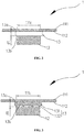
- the display device 1 includes a display panel 11, a fingerprint identification module 12, and a spacer 13.
- the display panel 11 includes a display surface 111 and a rear surface 112 opposite to the display surface 111.
- the display surface 111 includes a display region 111a for displaying images.
- the spacer 13 is attached to the rear surface 112 of the display panel 11.
- the spacer 13 is configured to separate the fingerprint identification module 12 from the rear surface 112 of the display panel 11.
- the fingerprint identification module 12 is configured to identify fingerprint information received by the display region 111a.
- the fingerprint identification module 12 may include a chip
- the fingerprint identification module 12 is attached to the display panel 11 by applying a heat-pressing process when the fingerprint identification module 12 is directly connected with the rear surface 112 of the display panel 11.
- the heat-pressing process may damage the display panel 11, and after the fingerprint identification module 12 is attached to the display panel 11, wrinkles may be generated at a connection of the fingerprint identification module 12 and the display panel 11, which may result in an incline to the fingerprint identification module 12 with respect to the display panel 11.
- This problem becomes more prominent when the display panel 11 is a flexible display panel such as an OLED (Organic Light-Emitting Diode) display panel.
- OLED Organic Light-Emitting Diode
- a connection structure of the fingerprint identification module 12 and the flexible display panel is more likely to bring wrinkles at the connection of the flexible display panel and the fingerprint identification module 12.
- the wrinkles may result in a large included angle between the flexible display panel and the fingerprint identification module 12.
- the fingerprint identification module 12 is a device that requires a small included angle between the flexible display panel and the fingerprint identification module 12 to ensure that the fingerprint identification module 12 may identify a fingerprint accurately, such as an optical fingerprint identification device. In this case, an accuracy of a fingerprint identification of the fingerprint identification module 12 is relatively low when there are wrinkles between the flexible display panel and the fingerprint identification module 12.
- the fingerprint identification module 12 is disposed apart from the rear surface 112 of the display panel 11 by disposing the spacer 13 between the fingerprint identification module 12 and the display panel 11. So that the fingerprint identification module 12 can be fixed in the mobile terminal 100 to identify the fingerprint information received by the display region 111a, and can be separated from the display panel 11. Thus the fingerprint identification module 12 is maintained to be parallel to the display panel 11, and the accuracy of fingerprint identification is improved.
- the display panel 11 is taken a flexible display panel capable of flexible bending as an example, in the illustrated embodiment.
- the display panel 11 can also be a hard screen such as the liquid crystal display 11.
- the display panel 11 is capable of displaying images and receiving a touch input to generate an instruction, that is, the display panel 11 has a display function and a touch function.
- the display surface 111 of the display panel 11 includes a display region 111a for displaying images and a non-display region 111b.
- the display region 111a is also capable of receiving fingerprint information, a ratio of the non-display region 111b to the display surface 111 is relatively small. On the contrary, the ratio of the display region 111a to the display surface 111 is greatly increased.
- display panel 11 may only have a display function.
- the fingerprint identification module 12 is an optical fingerprint identification device.
- the optical fingerprint identification device can emit a detecting light passing through the display panel 11 to the outside, and can receive the detecting light after being reflected by a fingerprint texture of a user when the user touches the display panel with a finger, wherein the detecting light after being reflected indicates fingerprint information.
- the display region 111a may define a fingerprint receiving region 111c to receive the fingerprint information.
- the fingerprint receiving region 111c allows the user to touch and input the fingerprint information.
- the fingerprint receiving region 111c is a region of the display region 111a, which is corresponding to an orthographic projection region of the fingerprint identification module 12 when the fingerprint identification module 12 is projected on the display region 111a.
- the user can press the fingerprint texture in the fingerprint receiving region 111c, thus the fingerprint identification module 12 may identify the fingerprint texture of the user, and allow user to control the mobile terminal 100, such as unlocking.
- the fingerprint identification module 12 can also be an ultrasonic fingerprint identification device.
- the ultrasonic fingerprint identification device may detect and identify the fingerprint texture by emitting and receiving ultrasonic waves.
- a distance d1 between the fingerprint identification module 12 and the rear surface 112 of the display panel 11 is greater than or equal to 0.1 mm.
- the distance d1 between the fingerprint identification module 12 and the rear surface 112 of the display panel 11 is 0.2 mm.
- the fingerprint identification module 12 is ensured to not directly connected to the display panel 11, and accurately detect the fingerprint information that is received by the display region 111a, when the distance d1 between the fingerprint identification module 12 and the rear surface 112 of the display panel 11 is 0.2 mm.
- the distance d1 between the fingerprint identification module 12 and the display panel 11 may also be 0.1 mm, 0.3 mm, etc..
- the spacer 13 is disposed on the rear surface 112 of the display panel 11.
- the spacer 13 is configured to ensure that the fingerprint identification module 12 and the rear surface 112 of the display panel 11 is spaced apart.
- the spacer 13 includes a first end surface 13a and a second end surface 13b opposite to the first end surface 13a.
- the first end surface 13a of the spacer 13 faces the rear surface 112 of the display panel 11.
- the second end surface 13b faces the fingerprint identification module 12.
- the first end surface 13a is fixed on the rear surface 112 of the display panel 11.
- the second end surface 13b is connected to the fingerprint identification module 12.
- a thickness of the spacer 13 is corresponding to the distance d1 between the fingerprint identification module 12 and the rear surface 112 of the display panel 11.
- the distance d1 between the fingerprint identification module 12 and the rear surface 112 is equal to the thickness of the spacer 13.
- an angle between an end surface of the spacer 13, which is connected to the rear surface 112, and another end surface of the spacer 13, which is connected to the fingerprint identification module 12, is less than 5°. That is, an included angle between the first end surface 13a and the second end surface 13b is less than 5°. Particularly, the included angle between the first end surface 13a and the second end surface 13b is 0°. That is, the first end surface 13a is parallel to the second end surface 13b, thereby ensuring an accurate of detection and identification for fingerprint information.
- the spacer 13 includes a transparent partition 131.
- the transparent partition 131 is disposed between the rear surface 112 of the display panel 11 and the fingerprint identification module 12, so that the fingerprint identification module 12 does not directly attach to the display panel 11, thereby ensuring that the fingerprint identification module 12 is parallel to the display panel 11, and the accuracy of the fingerprint identification of the fingerprint identification module 12 can be improved.
- the transparent partition 131 is a rectangular thin plate.
- the transparent partition 131 has a certain strength.
- the transparent partition 131 may have a thickness of 0.2 mm.
- the transparent partition 131 separates the rear surface 112 of the display panel 11 from the fingerprint identification module 12 by 0.2 mm.
- the transparent partition 131 may ensures that the fingerprint identification module 12 can emit the detecting light passing through the transparent partition 131 and the display panel 11, and may allow the detecting light after reflected to pass through the display panel 11 and the transparent partition 131 and finally arrive at the fingerprint identification module 12.
- the first end surface 13a of the transparent partition 131 is attached to the rear surface 112 of the display panel 11 by heat-pressing in a low temperature
- the fingerprint identification module 12 is attached to the second end surface 13b of the spacer 13 by heat-pressing in a high temperature. Because the transparent partition 131 has a certain hardness, a region of the display panel 11 corresponding to the transparent partition 131 may not be fold, when the display panel 11 is flexibly bent, thereby preventing generating the wrinkles on the region of the display panel 11 corresponding to the transparent partition 131. There is no wrinkles formed on the transparent partition 131 although the fingerprint identification module 12 is attached to the spacer 13 by heat-pressing in a high temperature.
- the fingerprint identification module 12 can be ensured to be parallel to the rear surface 112 of the display panel 11, thereby ensuring accurate detection and identification of fingerprint information.
- the fingerprint identification module 12 can directly resist against the second end surface 13b of the transparent partition 131 by positional relationships of components in the mobile terminal 100.
- the spacer 13 further includes multiple protrusions 132.
- the protrusions 132 are disposed on an end surface of the transparent partition 131 facing the rear surface 112 of the display panel 11 (i.e. the first end surface 13a); and/or; the protrusions 132 are disposed on the one end surface of the transparent partition 131 facing the fingerprint identification module 12 (i.e. the second end surface 13b).
- the protrusions 132 is disposed on the transparent partition 131, an area of contacting region of the transparent partition 131 and the rear surface 112 of the display panel 11 may be reduced, and/or an area of contacting region of the transparent partition 131 and the fingerprint identification module 12 is reduced. Therefore the rear surface 112 of the display panel 11 may be ensured to be parallel to the fingerprint identification module, and the accuracy of the fingerprint identification of the fingerprint identification module 12 can be improved.
- each of the protrusions 132 is a cylindrical protrusion, and the multiple protrusions 132 are respectively disposed on the first end surface 13a of the spacer 131 and the second end surface 13b of the spacer 131.
- the area of contacting region of the transparent partition 131 and the rear surface 112 of the display panel 11 may be reduced obviously, as well as the area of contacting region of the transparent partition 131 and the fingerprint identification module 12.
- the display panel 11 is bent during daily use, no large wrinkles are formed in the connection between the rear surface 112 of the display panel 11 and the transparent partition 131, which may avoid affecting the detection of fingerprint information.
- the protrusions 132 may be disposed only on the first end surface 13a of the spacer 131. In other embodiments, as illustrated in FIG. 5 , the protrusions 132 may be disposed only on the second end surface 13b of the spacer 131.
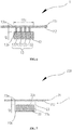
- the spacer 13 includes multiple transparent columns 133.
- the transparent columns 133 are sandwiched between the rear surface 112 of the display panel 11 and the fingerprint identification module.
- the multiple transparent columns 133 are evenly spaced distributed.
- each of the transparent columns 133 has a shape of cylinder, and each of the transparent columns 133 has a diameter of 0.1 mm, and a height of 0.2 mm.
- Each of the transparent columns 133 includes a first end surface 13a close to the rear surface 112 of the display panel 11, and a second end surface 13b close to the fingerprint identification module 12.
- the first end surface 13a of the transparent columns 133 is attached to the rear surface 112 of the display panel 11 by heat-pressing in a low temperature
- the fingerprint identification module 12 is attached to the second end surface 13b of the transparent columns 133 by heat-pressing in a high temperature.
- the spacer 13 is formed by the multiple transparent columns 133, the spacer 13 is brought into contact with the display panel 11 and the fingerprint identification module 12 in point contact, an area of contacting region of the multiple transparent columns 133 and the rear surface 112 of the display panel 11 is small, as well as an area of contacting region of the multiple transparent columns 133 and fingerprint identification module 12.
- the display panel 11 is bent during daily use, no large wrinkles are formed in the connection between the rear surface 112 of the display panel 11 and the multiple transparent columns 133, which may avoid affecting the detection of fingerprint information.
- the first end surface 13a of the spacer 13 (including the two above mentioned structures of the spacers 13) is attached to the rear surface 112 of the display panel 11 by heat-pressing, and the fingerprint identification module 12 is fixed to the second end surface 13b of the spacer 13. Because the spacer 13 has a certain hardness, a region of the display panel 11 corresponding to the spacer 13 may not be bent to cause wrinkles when the display panel 11 is flexibly bent. There is no wrinkles formed on the spacer 13 although the fingerprint identification module 12 is attached to the spacer 13 by heat-pressing in a high temperature.
- the fingerprint identification module 12 can be ensured to be parallel to the rear surface 112 of the display panel 11, thereby ensuring accurate detection and identification of fingerprint information.
- the user can press the fingerprint texture in the fingerprint receiving region 111c, thus the fingerprint identification module 12 may identify the fingerprint texture of the user.
- a region of the display panel 11 corresponding to the spacer 13 may not be bent when the mobile terminal 100 is bent. Therefore the fingerprint identification module 12 can be ensured to be parallel to the display panel 11, thereby ensuring accurate detection and identification of fingerprint information.
- the fingerprint identification module 12 is disposed adjacent to the rear surface 112 of the display panel 11, which allows the user to input fingerprint information through the display region 111a of the display panel 110. Thereby a ratio of the display region 111a to the display surface 111 of the mobile terminal 100 is increased.
- the fingerprint identification module 12 is disposed apart from the rear surface 112 of the display panel 11 by the spacer 13, so that the fingerprint identification module 12 does not directly contact with the display panel 11 to avoid affecting the detection of fingerprint information, that is, the accuracy of fingerprint identification is improved.
- a mobile terminal 200 is provided, in accordance with a second embodiment of present disclosure.
- the mobile terminal 200 is substantially the same as the mobile terminal 100 of the first embodiment, except that an end surface(herein defined as a second end face 23b) of the spacer 23 facing the fingerprint identification module 12 defines a recess 23c, and the fingerprint identification module 22 is received in the recess 23c of the spacer 23.
- the spacer 23 is a rectangular block.
- the recess 23c of the spacer 23 is substantially the same size as the fingerprint identification module 22.
- a bottom surface 23d of the recess 23c is parallel to an end surface of to the spacer 14 facing the rear surface 112 of the display panel 11 (herein the end surface is defined as a first end surface 23a). So that the fingerprint identification module 22 is still parallel to the rear surface212 of the display panel 21 when the fingerprint identification module 22 is received in the recess 23c, to ensure a better fingerprint. identification accuracy.
- a distance between the first end surface 23a of the spacer 23 and a bottom surface 23d of the recess 23c equals to a distance d2 between the fingerprint identification module 22 and the rear surface212 of the display panel 21.
- the fingerprint identification module is accommodated in the recess 23c of the spacer 23, thus a space inside the mobile terminal 200 may be saved, and the structure of the mobile terminal 200 may be further optimized.
- connection manners, connection structures and manners of the spacer 13 and the rear surface 112 of the display panel 11 in the first embodiment of the present disclosure may be applied in the second embodiment, and details are not described herein.
Landscapes
- Engineering & Computer Science (AREA)
- Theoretical Computer Science (AREA)
- Computer Hardware Design (AREA)
- Human Computer Interaction (AREA)
- Physics & Mathematics (AREA)
- General Physics & Mathematics (AREA)
- General Engineering & Computer Science (AREA)
- Signal Processing (AREA)
- Multimedia (AREA)
- Devices For Indicating Variable Information By Combining Individual Elements (AREA)
- Telephone Set Structure (AREA)
- Image Input (AREA)
Applications Claiming Priority (2)
| Application Number | Priority Date | Filing Date | Title |
|---|---|---|---|
| CN201710341780.XA CN107256067B (zh) | 2017-05-12 | 2017-05-12 | 显示装置和移动终端 |
| PCT/CN2018/085211 WO2018205864A1 (zh) | 2017-05-12 | 2018-04-28 | 显示装置和移动终端 |
Publications (2)
| Publication Number | Publication Date |
|---|---|
| EP3617832A1 true EP3617832A1 (de) | 2020-03-04 |
| EP3617832A4 EP3617832A4 (de) | 2020-05-20 |
Family
ID=60027980
Family Applications (1)
| Application Number | Title | Priority Date | Filing Date |
|---|---|---|---|
| EP18798459.6A Withdrawn EP3617832A4 (de) | 2017-05-12 | 2018-04-28 | Anzeigevorrichtung und mobiles endgerät |
Country Status (4)
| Country | Link |
|---|---|
| US (1) | US11132521B2 (de) |
| EP (1) | EP3617832A4 (de) |
| CN (1) | CN107256067B (de) |
| WO (1) | WO2018205864A1 (de) |
Families Citing this family (9)
| Publication number | Priority date | Publication date | Assignee | Title |
|---|---|---|---|---|
| CN107256067B (zh) | 2017-05-12 | 2021-03-09 | Oppo广东移动通信有限公司 | 显示装置和移动终端 |
| CN109416558B (zh) * | 2017-06-14 | 2022-09-09 | 华为技术有限公司 | 一种显示模组及移动终端 |
| CN108323207B (zh) * | 2018-02-06 | 2021-02-26 | 深圳市汇顶科技股份有限公司 | 屏下生物特征识别装置、生物特征识别组件和终端设备 |
| CN109496311A (zh) * | 2018-10-26 | 2019-03-19 | 深圳市汇顶科技股份有限公司 | 屏下生物特征识别装置和电子设备 |
| CN111222391A (zh) * | 2018-11-27 | 2020-06-02 | 北京小米移动软件有限公司 | 显示屏及电子设备 |
| US10642313B1 (en) | 2018-12-13 | 2020-05-05 | Innolux Corporation | Foldable display device and operation method of electronic device |
| CN113383343A (zh) * | 2019-07-05 | 2021-09-10 | 深圳市柔宇科技股份有限公司 | 电子装置及其柔性显示装置 |
| WO2021007836A1 (zh) * | 2019-07-18 | 2021-01-21 | 深圳市柔宇科技有限公司 | 电子装置 |
| CN111401254A (zh) * | 2020-03-17 | 2020-07-10 | 泸州市艾乐丰科技有限公司 | 一种高精度指纹识别设备 |
Family Cites Families (12)
| Publication number | Priority date | Publication date | Assignee | Title |
|---|---|---|---|---|
| JP5433465B2 (ja) * | 2010-03-16 | 2014-03-05 | 株式会社ジャパンディスプレイ | 表示装置 |
| CN104036172B (zh) * | 2014-07-02 | 2017-08-08 | 南昌欧菲生物识别技术有限公司 | 指纹识别检测组件及其电子装置 |
| US9886613B2 (en) * | 2014-07-07 | 2018-02-06 | Shenzhen GOODIX Technology Co., Ltd. | Integration of touch screen and fingerprint sensor assembly |
| CN104779222B (zh) * | 2015-04-10 | 2017-11-03 | 华进半导体封装先导技术研发中心有限公司 | 生物识别模组结构与制作方法 |
| CN107004130B (zh) * | 2015-06-18 | 2020-08-28 | 深圳市汇顶科技股份有限公司 | 用于屏幕上指纹感应的屏幕下光学传感器模块 |
| CN105094227A (zh) * | 2015-07-10 | 2015-11-25 | 麦克思商务咨询(深圳)有限公司 | 电子装置 |
| CN205721719U (zh) * | 2016-04-22 | 2016-11-23 | 上海与德通讯技术有限公司 | 显示模组及电子设备 |
| CN205656556U (zh) * | 2016-05-25 | 2016-10-19 | 广东欧珀移动通信有限公司 | 一种移动终端 |
| CN205983304U (zh) * | 2016-06-30 | 2017-02-22 | 京东方科技集团股份有限公司 | 显示装置及用户终端 |
| CN205809952U (zh) * | 2016-07-01 | 2016-12-14 | 维沃移动通信有限公司 | 一种指纹识别模组的连接结构 |
| CN106558279B (zh) * | 2017-01-13 | 2019-05-14 | 京东方科技集团股份有限公司 | 柔性显示装置及其制备方法 |
| CN107256067B (zh) * | 2017-05-12 | 2021-03-09 | Oppo广东移动通信有限公司 | 显示装置和移动终端 |
-
2017
- 2017-05-12 CN CN201710341780.XA patent/CN107256067B/zh not_active Expired - Fee Related
-
2018
- 2018-04-28 EP EP18798459.6A patent/EP3617832A4/de not_active Withdrawn
- 2018-04-28 WO PCT/CN2018/085211 patent/WO2018205864A1/zh not_active Ceased
-
2019
- 2019-11-06 US US16/675,771 patent/US11132521B2/en active Active
Also Published As
| Publication number | Publication date |
|---|---|
| US20200074141A1 (en) | 2020-03-05 |
| CN107256067A (zh) | 2017-10-17 |
| US11132521B2 (en) | 2021-09-28 |
| CN107256067B (zh) | 2021-03-09 |
| EP3617832A4 (de) | 2020-05-20 |
| WO2018205864A1 (zh) | 2018-11-15 |
Similar Documents
| Publication | Publication Date | Title |
|---|---|---|
| EP3617832A1 (de) | Anzeigevorrichtung und mobiles endgerät | |
| US11086159B2 (en) | Electronic device provided with input detection panel | |
| EP3279778B1 (de) | Elektronische vorrichtung mit fingerabdrucksensor | |
| US10607057B2 (en) | Electronic device including biometric sensor | |
| US11256347B2 (en) | Electronic device equipped with pressure sensors | |
| US10411702B2 (en) | Electronic device including input apparatus | |
| US10510980B2 (en) | Display module | |
| CN105975118B (zh) | 数字化电路图案化方法和支持其的电子装置 | |
| US9690329B2 (en) | Display module and display apparatus having the same | |
| US10782817B2 (en) | Input device and electronic apparatus comprising the same | |
| US11031717B2 (en) | Dual contact member and electronic device therewith | |
| KR20180044764A (ko) | 압력 센서를 포함하는 전자 장치 | |
| US20180081463A1 (en) | Touch control liquid crystal display device and electronic apparatus | |
| WO2019153372A1 (zh) | 一种显示装置 | |
| US20190244002A1 (en) | Display device | |
| CN107003746A (zh) | 输入设备、传感器、键盘和电子设备 | |
| JP2017068830A (ja) | タッチディスプレイ装置 | |
| US20160378231A1 (en) | Display device | |
| CN107621712A (zh) | 一种液晶屏模组及显示终端 | |
| CN110298288B (zh) | 显示屏、电子设备及其控制方法 | |
| US10372253B2 (en) | Touch display device and backlight unit thereof | |
| CN112130688B (zh) | 显示屏、电子设备及其控制方法 | |
| KR102809970B1 (ko) | 메탈 메쉬 터치 전극을 포함하는 전자 장치 | |
| US20190235727A1 (en) | Electronic device including touch key | |
| CN106445241A (zh) | 触控显示屏、触点识别方法及模块、触控显示装置 |
Legal Events
| Date | Code | Title | Description |
|---|---|---|---|
| STAA | Information on the status of an ep patent application or granted ep patent |
Free format text: STATUS: THE INTERNATIONAL PUBLICATION HAS BEEN MADE |
|
| PUAI | Public reference made under article 153(3) epc to a published international application that has entered the european phase |
Free format text: ORIGINAL CODE: 0009012 |
|
| STAA | Information on the status of an ep patent application or granted ep patent |
Free format text: STATUS: REQUEST FOR EXAMINATION WAS MADE |
|
| 17P | Request for examination filed |
Effective date: 20191129 |
|
| AK | Designated contracting states |
Kind code of ref document: A1 Designated state(s): AL AT BE BG CH CY CZ DE DK EE ES FI FR GB GR HR HU IE IS IT LI LT LU LV MC MK MT NL NO PL PT RO RS SE SI SK SM TR |
|
| AX | Request for extension of the european patent |
Extension state: BA ME |
|
| A4 | Supplementary search report drawn up and despatched |
Effective date: 20200420 |
|
| RIC1 | Information provided on ipc code assigned before grant |
Ipc: G06K 9/00 20060101ALI20200414BHEP Ipc: H04M 1/02 20060101ALI20200414BHEP Ipc: G06F 1/16 20060101AFI20200414BHEP Ipc: H04M 1/67 20060101ALI20200414BHEP Ipc: H04M 1/66 20060101ALI20200414BHEP |
|
| DAV | Request for validation of the european patent (deleted) | ||
| DAX | Request for extension of the european patent (deleted) | ||
| STAA | Information on the status of an ep patent application or granted ep patent |
Free format text: STATUS: EXAMINATION IS IN PROGRESS |
|
| 17Q | First examination report despatched |
Effective date: 20220301 |
|
| 17Q | First examination report despatched |
Effective date: 20220302 |
|
| REG | Reference to a national code |
Ref country code: DE Ref legal event code: R079 Free format text: PREVIOUS MAIN CLASS: G06F0001160000 Ipc: G06V0040130000 |
|
| GRAP | Despatch of communication of intention to grant a patent |
Free format text: ORIGINAL CODE: EPIDOSNIGR1 |
|
| STAA | Information on the status of an ep patent application or granted ep patent |
Free format text: STATUS: GRANT OF PATENT IS INTENDED |
|
| RIC1 | Information provided on ipc code assigned before grant |
Ipc: H04M 1/67 20060101ALI20240513BHEP Ipc: H04M 1/02 20060101ALI20240513BHEP Ipc: G06F 1/16 20060101ALI20240513BHEP Ipc: G06V 40/13 20220101AFI20240513BHEP |
|
| INTG | Intention to grant announced |
Effective date: 20240528 |
|
| STAA | Information on the status of an ep patent application or granted ep patent |
Free format text: STATUS: THE APPLICATION IS DEEMED TO BE WITHDRAWN |
|
| 18D | Application deemed to be withdrawn |
Effective date: 20241001 |