EP3617837A1 - Application et intégration d'un système serveur sans câble - Google Patents
Application et intégration d'un système serveur sans câble Download PDFInfo
- Publication number
- EP3617837A1 EP3617837A1 EP19176266.5A EP19176266A EP3617837A1 EP 3617837 A1 EP3617837 A1 EP 3617837A1 EP 19176266 A EP19176266 A EP 19176266A EP 3617837 A1 EP3617837 A1 EP 3617837A1
- Authority
- EP
- European Patent Office
- Prior art keywords
- board
- modules
- server system
- power
- linking
- Prior art date
- Legal status (The legal status is an assumption and is not a legal conclusion. Google has not performed a legal analysis and makes no representation as to the accuracy of the status listed.)
- Withdrawn
Links
Images












Classifications
-
- H—ELECTRICITY
- H05—ELECTRIC TECHNIQUES NOT OTHERWISE PROVIDED FOR
- H05K—PRINTED CIRCUITS; CASINGS OR CONSTRUCTIONAL DETAILS OF ELECTRIC APPARATUS; MANUFACTURE OF ASSEMBLAGES OF ELECTRICAL COMPONENTS
- H05K7/00—Constructional details common to different types of electric apparatus
- H05K7/14—Mounting supporting structure in casing or on frame or rack
- H05K7/1485—Servers; Data center rooms, e.g. 19-inch computer racks
- H05K7/1488—Cabinets therefor, e.g. chassis or racks or mechanical interfaces between blades and support structures
- H05K7/1492—Cabinets therefor, e.g. chassis or racks or mechanical interfaces between blades and support structures having electrical distribution arrangements, e.g. power supply or data communications
-
- G—PHYSICS
- G06—COMPUTING OR CALCULATING; COUNTING
- G06F—ELECTRIC DIGITAL DATA PROCESSING
- G06F1/00—Details not covered by groups G06F3/00 - G06F13/00 and G06F21/00
- G06F1/26—Power supply means, e.g. regulation thereof
-
- G—PHYSICS
- G06—COMPUTING OR CALCULATING; COUNTING
- G06F—ELECTRIC DIGITAL DATA PROCESSING
- G06F1/00—Details not covered by groups G06F3/00 - G06F13/00 and G06F21/00
- G06F1/16—Constructional details or arrangements
- G06F1/18—Packaging or power distribution
- G06F1/181—Enclosures
-
- G—PHYSICS
- G06—COMPUTING OR CALCULATING; COUNTING
- G06F—ELECTRIC DIGITAL DATA PROCESSING
- G06F1/00—Details not covered by groups G06F3/00 - G06F13/00 and G06F21/00
- G06F1/16—Constructional details or arrangements
- G06F1/18—Packaging or power distribution
- G06F1/183—Internal mounting support structures, e.g. for supporting printed circuit boards
-
- G—PHYSICS
- G06—COMPUTING OR CALCULATING; COUNTING
- G06F—ELECTRIC DIGITAL DATA PROCESSING
- G06F1/00—Details not covered by groups G06F3/00 - G06F13/00 and G06F21/00
- G06F1/16—Constructional details or arrangements
- G06F1/18—Packaging or power distribution
- G06F1/183—Internal mounting support structures, e.g. for supporting printed circuit boards
- G06F1/184—Mounting of motherboards
-
- G—PHYSICS
- G06—COMPUTING OR CALCULATING; COUNTING
- G06F—ELECTRIC DIGITAL DATA PROCESSING
- G06F1/00—Details not covered by groups G06F3/00 - G06F13/00 and G06F21/00
- G06F1/16—Constructional details or arrangements
- G06F1/18—Packaging or power distribution
- G06F1/183—Internal mounting support structures, e.g. for supporting printed circuit boards
- G06F1/185—Mounting of expansion boards
-
- G—PHYSICS
- G06—COMPUTING OR CALCULATING; COUNTING
- G06F—ELECTRIC DIGITAL DATA PROCESSING
- G06F1/00—Details not covered by groups G06F3/00 - G06F13/00 and G06F21/00
- G06F1/16—Constructional details or arrangements
- G06F1/18—Packaging or power distribution
- G06F1/183—Internal mounting support structures, e.g. for supporting printed circuit boards
- G06F1/188—Mounting of power supply units
-
- G—PHYSICS
- G06—COMPUTING OR CALCULATING; COUNTING
- G06F—ELECTRIC DIGITAL DATA PROCESSING
- G06F1/00—Details not covered by groups G06F3/00 - G06F13/00 and G06F21/00
- G06F1/16—Constructional details or arrangements
- G06F1/20—Cooling means
-
- G—PHYSICS
- G06—COMPUTING OR CALCULATING; COUNTING
- G06F—ELECTRIC DIGITAL DATA PROCESSING
- G06F13/00—Interconnection of, or transfer of information or other signals between, memories, input/output devices or central processing units
- G06F13/38—Information transfer, e.g. on bus
- G06F13/40—Bus structure
-
- H—ELECTRICITY
- H05—ELECTRIC TECHNIQUES NOT OTHERWISE PROVIDED FOR
- H05K—PRINTED CIRCUITS; CASINGS OR CONSTRUCTIONAL DETAILS OF ELECTRIC APPARATUS; MANUFACTURE OF ASSEMBLAGES OF ELECTRICAL COMPONENTS
- H05K5/00—Casings, cabinets or drawers for electric apparatus
- H05K5/0026—Casings, cabinets or drawers for electric apparatus provided with connectors and printed circuit boards [PCB], e.g. automotive electronic control units
-
- H—ELECTRICITY
- H05—ELECTRIC TECHNIQUES NOT OTHERWISE PROVIDED FOR
- H05K—PRINTED CIRCUITS; CASINGS OR CONSTRUCTIONAL DETAILS OF ELECTRIC APPARATUS; MANUFACTURE OF ASSEMBLAGES OF ELECTRICAL COMPONENTS
- H05K7/00—Constructional details common to different types of electric apparatus
- H05K7/02—Arrangements of circuit components or wiring on supporting structure
-
- H—ELECTRICITY
- H05—ELECTRIC TECHNIQUES NOT OTHERWISE PROVIDED FOR
- H05K—PRINTED CIRCUITS; CASINGS OR CONSTRUCTIONAL DETAILS OF ELECTRIC APPARATUS; MANUFACTURE OF ASSEMBLAGES OF ELECTRICAL COMPONENTS
- H05K7/00—Constructional details common to different types of electric apparatus
- H05K7/14—Mounting supporting structure in casing or on frame or rack
- H05K7/1485—Servers; Data center rooms, e.g. 19-inch computer racks
- H05K7/1487—Blade assemblies, e.g. blade cases or inner arrangements within a blade
-
- H—ELECTRICITY
- H05—ELECTRIC TECHNIQUES NOT OTHERWISE PROVIDED FOR
- H05K—PRINTED CIRCUITS; CASINGS OR CONSTRUCTIONAL DETAILS OF ELECTRIC APPARATUS; MANUFACTURE OF ASSEMBLAGES OF ELECTRICAL COMPONENTS
- H05K7/00—Constructional details common to different types of electric apparatus
- H05K7/20—Modifications to facilitate cooling, ventilating, or heating
- H05K7/20009—Modifications to facilitate cooling, ventilating, or heating using a gaseous coolant in electronic enclosures
- H05K7/20136—Forced ventilation, e.g. by fans
- H05K7/20172—Fan mounting or fan specifications
Definitions
- the disclosure generally relates to computer server systems, more particularly to cableless server systems.
- Modern computing systems comprise numerous electronic circuit boards and components. Traditionally, a plurality of cables is used to interconnect these electronic circuit boards or at least some of these electronic components. However, connecting via cables requires connectors. As a server system becomes more complex, and incorporates more electronic circuit boards and components, it can be difficult to locate a large number of connectors for cable connections inside the server system. Also, cables are subject to inadvertent impingement due to moving parts within the server system. Thus, maintaining and verifying these cable connections can be challenging.
- the server system comprises a motherboard (MB) module, a power distribution board (PDB) module, power supply unit (PSU) modules, network interface controller (NIC) modules, fan modules, graphic process unit (GPU) modules, and a hyperscale GPU accelerator (HGX) platform.
- MB motherboard
- PDB power distribution board
- PSU power supply unit
- NIC network interface controller
- fan modules fan modules
- GPU graphic process unit
- HGX hyperscale GPU accelerator
- the plurality of circuit boards includes, but is not limited to, a main board, linking boards (BDs), a PDB, a fan board, a power linking board (e.g., a PSU linking board), peripheral-component-interconnect-express (PCIe) expander boards, a plurality of NVLink bridges (e.g., NVLink boards), and HGX base boards.
- BDs linking boards
- PDB power linking board
- PCIe peripheral-component-interconnect-express
- NVLink bridges e.g., NVLink boards
- HGX base boards HGX base boards.
- a computer-implemented method for assembling a cableless server system comprises: inserting a power distribution board (PDB) module, a power linking board, and a plurality of NVLink bridges onto a first side, a second side, and a rear side of the server system, respectively, the server system comprising a motherboard (MB) module, power supply unit (PSU) modules, network interface controller (NIC) modules, fan modules, graphic process unit (GPU) modules, and a hyperscale GPU accelerator (HGX) platform, wherein components of the server system are interconnected via a main board, linking boards (BDs), a PDB, a fan board, the power linking board, a peripheral-component-interconnect-express (PCIe) expander board, the plurality of NVLink bridges, and a HGX base board; inserting the GPU modules from a front side of the server system, each of the GPU modules comprising a linking board; connecting the power linking board to a corresponding linking board
- PCIe peripheral-component-inter
- a power distribution board (PDB) module, a power linking board, and a plurality of NVLink bridges are inserted onto a first side, a second side, and a rear side of the server system, respectively.
- the server system comprises a motherboard (MB) module, power supply unit (PSU) modules, network interface controller (NIC) modules, fan modules, graphic process unit (GPU) modules, and a hyperscale GPU accelerator (HGX) platform.
- the components of the server system are interconnected via a main board, linking boards (BDs), a PDB, a fan board, the power linking board, a peripheral-component-interconnect-express (PCIe) expander board, the plurality of NVLink bridges, and a HGX base board.
- the GPU modules are inserted from a front side of the server system, with each of the GPU modules comprising a linking board.
- the power linking board is connected to a corresponding linking board of each of the GPU modules.
- a fan bay main module is installed from the rear side of the server system, and the MB module is installed from the front side of the server system.
- the main board connects to the PDB, and the fan board is connected to the power linking board.
- the PSU modules are inserted into the rear side of the server system.
- the PSU modules are connected to an AC power source to deliver power to the server system.
- a non-transitory computer-readable storage medium storing instructions.
- the instructions when executed by a processor of a cableless server system, cause the processor to perform operations including: inserting a power distribution board (PDB) module, a power linking board, and a plurality of NVLink bridges onto a first side, a second side, and a rear side of the server system, respectively, the server system comprising a motherboard (MB) module, power supply unit (PSU) modules, network interface controller (NIC) modules, fan modules, graphic process unit (GPU) modules, and a hyperscale GPU accelerator (HGX) platform, wherein components of the server system are interconnected via a main board, linking boards (BDs), a PDB, a fan board, the power linking board, a peripheral-component-interconnect-express (PCIe) expander board, the plurality of NVLink bridges, and a HGX base board; inserting the GPU modules from a front side of the server system, each
- a third aspect of the present disclosure is a non-transitory computer-readable storage medium storing instructions.
- the instructions when executed by a processor of a cableless server system, cause the processor to perform certain operations.
- a power distribution board (PDB) module, a power linking board, and a plurality of NVLink bridges are inserted onto a first side, a second side, and a rear side of the server system, respectively.
- the server system comprises a motherboard (MB) module, power supply unit (PSU) modules, network interface controller (NIC) modules, fan modules, graphic process unit (GPU) modules, and a hyperscale GPU accelerator (HGX) platform.
- the components of the server system are interconnected via a main board, linking boards (BDs), a PDB, a fan board, the power linking board, a peripheral-component-interconnect-express (PCIe) expander board, the plurality of NVLink bridges, and a HGX base board.
- the GPU modules are inserted from a front side of the server system, with each of the GPU modules comprising a linking board.
- the power linking board is connected to a corresponding linking board of each of the GPU modules.
- a fan bay main module is installed from the rear side of the server system, and the MB module is installed from the front side of the server system.
- the main board is connected to the PDB, and the fan board is connected to the power linking board.
- the PSU modules are inserted into the rear side of the server system.
- the PSU modules are connected to an AC power source to deliver power to the server system.
- the server system comprises a MB module, a PDB module, PSU modules, NIC modules, fan modules, GPU modules, and a HGX platform. These components of the server system are interconnected by a plurality of circuit boards.
- the plurality of circuit boards includes a main board, linking BDs, a PDB, a fan board, the power linking board, a PCIe expander board, the plurality of NVLink bridges, and a HGX base board.
- FIG. 1A illustrates a schematic block diagram of an exemplary cableless server system 100A, in accordance with an implementation of the present disclosure.
- the server system 100A includes a MB module 101, a PDB module 102, PSU modules 105, NIC modules 103, fan bay main modules 106, GPU modules 123 (e.g., HGX2 modules), and HGX platforms 104.
- the PSU modules 105 are configured to receive an AC power from an AC power supply, and provide power to various components of the server system 100A.
- the HGX platforms 104 are cloud server platforms for artificial intelligence (AI) and high-performance computing (HPC).
- the NIC modules 103 are configured to connect the server system 100A to a computer network.
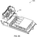
- the NIC modules 103 and the HGX2 modules are connected via ExaMax connectors 203, as illustrated in FIGs. 2N and 2O .
- GPU modules are inter-connected via Linking BD-1 109, as illustrated in FIG. 2E .
- fan modules are connected via power linking board 112, as illustrated in FIG. 2G .
- the GPU modules 123 and the NVLink bridges are connected via ExaMax connectors 201, as illustrated in FIG. 2K .
- the GPU modules 123 and the linking BD-1 109 are connected via AirMax power connectors 118, as illustrated in FIG. 2L .
- the fan board 111 and the power linking board 112 are connected via fan power connectors 120, as illustrated in FIG. 2G .
- the GPU modules 123 or FPGAs are connected to a processor of the server system 100A via PCIe switches.
- the PCIe switches enable highspeed serial point-to-point connections among multiple I/O devices, GPUs modules 123 or FPGAs, and the processor for optimized aggregation, fan-out, or peer-to-peer communication of end-point traffic to a host.
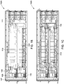
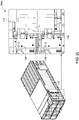
- FIGs. 1B and 1C illustrate schematic block diagrams of a plurality of circuit boards that connect various components of the exemplary cableless server system 100A, in accordance with an implementation of the present disclosure.
- the plurality of circuit boards comprises a main board 108, linking BDs 109, a PDB 110, fan boards 111, a power link board or bridge 112, PCIe expander boards 113, a plurality of NVLink bridges or boards 115, and HGX base boards 114.
- the main board 108, the linking BDs 109, the PDB 110, and the fan boards 111 are placed next to each other ranging from a front panel 107 to a rear side of the server system 100A.
- the main board 108 is configured to provide system control (e.g., baseboard management controller (BMC)).
- the PDB 110 is configured to provide main power distribution and management.
- the NVLink bridges 115 can provide signal transfer for HGX2.
- the linking BDs 109 can transfer signals and power within the PDB 110 and PCIe expander boards 113.
- the PCIe expander boards 113 can support 100G network interface card.
- the PCIe expander boards 113 can be PCIe GEN3/4.
- the power linking board 112 can transfer and manage a main power source to all systems.
- the fan board 111 can manage power delivered to fans within the system 100A, and control fan speeds of the fans.
- the main board 108 and the PDB module 102 are connected via a high density power connector, as illustrated in FIG. 2J .
- the PCIe expander boards 113 are placed between the front panel 107 and the power link board or bridge 112.
- the PCIe expander boards 113 and the linking BD 109 are connected via PCIe express connector 202, as illustrated in FIG. 2M .
- the plurality of NVLink bridges or boards 115 are situated close to the rear side of the server system 100A, and are configured to transfer signals within the HGX2 modules without providing power.
- the power link board 112 and the HGX base boards 114 e.g., GPU boards
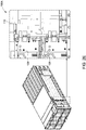
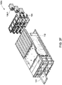
- FIGs. 2A-2I illustrate the exemplary cableless server system 100A of FIG. 1A in individual assembly steps, in accordance with an implementation of the present disclosure.
- FIG. 2A illustrates that the PDB module 102, the power linking board 112, and the NVlink board or bridge 116 are being inserted onto side walls and a rear side of the server system 100A, respectively.
- the PDB module 102 is inserted into a first side wall; the power linking board 112 is inserted into a second side wall; and the NVlink board or bridge 116 is inserted onto the rear side of the server system 100A.
- the PDB module 102 is connected to the power linking board 112 via connectors.
- the connections between the PDB module 102 and the power linking board 112 is further illustrated in FIG. 2B .
- the PDB module 102 and the power linking board 112 are connected via high speed orthogonal connectors (e.g., ExaMax Power Connectors 117-1 and 117-2).
- FIG. 2C further illustrates connectors of the power linking board 112.
- the power linking board 112 further includes orthogonal connectors (e.g., AirMax connectors 118), guiding pins 119, fan power connectors 120, power connectors 121, and guiding pins 122.
- the AirMax connectors 118 of the linking BD 109 are connected to AirMax connectors of the power linking board 112.
- the guiding pins 119 are configured to facilitate connection between the linking BD 109 and the power linking board 112.
- the connection between the linking BD 109 and the power linking board 112 are further illustrated in FIG. 2P .
- AirMax connectors 118 are used to connect the linking BD-1 109 and the power linking board 112, together with the guide pin 204 and guiding holder 205.
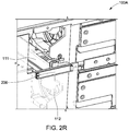
- each fan board 111 is connected to the power linking board 112 via the power connector 206, as illustrated in FIG. 2R .
- FIG. 2D illustrates two GPU modules 123 are being inserted from the front side of the server system 100A.
- Each of the GPU modules 123 comprises a linking BD 109 to be connected to the power linking board 112.
- FIG. 2E further illustrates connections between the linking BDs 109, and the power linking board 112 located on the second side of the server system 100A.
- FIG. 2F illustrates a MB module 101 being inserted from the front side of the server system 100A while a fan bay main module 106 being inserted from the rear side of the server system 100A.
- the MB module 101 can be connected to the PDB module 102 via power connectors 210, as illustrated in FIG. 2T .
- the fan bay main module 106 comprises a plurality of fans (e.g., 106-1).
- the fan bay main module 106 can be inserted into the system 100A from the rear side, and move leftward to be connected with the power linking board 112.
- the fan board 111 and the power linking board 112 are connected via fan power connectors 211, as illustrated in FIG. 2U .
- FIG. 2G illustrates a fan board 111 being inserted from the rear side of the server system 100A.
- the fan board 111 is connected to the power linking board 112 via fan power connectors 120 on the fan board 111 and the power connectors 121 (e.g., AirMax connectors) on the power linking board 112.
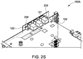
- the power connectors 121 of the power linking board 112 can also be used to connect to AirMax Power Connector 209 of the PDB module 102, as illustrated in FIG. 2S .
- guiding pins 122 and guiding holder 208 can also be used to facilitate connections between the power linking board 112 and the PDB module 102.
- FIG. 2H illustrates the plurality of PSU modules 105 being inserted from the rear side of the server system 100A.
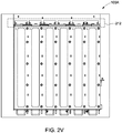
- PSU modules 105 are linked via PSU connector 212 in the PDB module 102, which is illustrated in FIG. 2V .
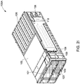
- FIG. 2I further illustrates the server system 100A comprising the MB module 101, the GPU modules 123, the PDB module 102, the PSU modules 105, the fan bay main module 106, the power linking module 112, and the linking BDs.
- the plurality of circuit boards can be used to set a cableless topology in the server system 100A.
- the above discussion is meant to be illustrative of the principles and various examples of the present disclosure. Numerous variations and modifications will become apparent once the above disclosure is fully appreciated.
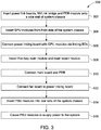
- FIG. 3 is an exemplary method 300 for assembling a cableless server system, in accordance with an implementation of the present disclosure. It should be understood that the exemplary method 300 is presented solely for illustrative purposes, and that other methods in accordance with the present disclosure can include additional, fewer, or alternative steps performed in similar or alternative orders, or in parallel.
- the exemplary method 300 starts at step 302 by inserting a power linking board, a plurality of NVLink bridges, and a PDB module onto a first side wall, a second side wall, and a rear side of the server system, respectively.
- the PDB module is connected to the power liking board via high speed orthogonal connectors, as illustrated in FIGs. 2A and 2B .
- the server system comprises a MB module, PSU modules, NIC modules, fan modules, GPU modules, and a HGX platform.
- Components of the server system are interconnected via a main board, linking BDs, a PDB, a fan board, the power linking board, a PCIe expander board, the plurality of NVLink bridges, and a HGX base board.
- the GPU modules are inserted from a front side of the server system, as illustrated in FIG. 2D .
- Each of the GPU modules comprises a linking BD.
- the power linking board is connected to a corresponding linking BD of each of the GPU modules, as illustrated in FIG. 2E .
- a fan bay main module, and the MB module are installed onto the server system, as illustrated in FIG. 2F .
- the fan bay main module comprises a plurality of fan modules.
- the main board is connected to the PDB.
- the fan board is connected to the power linking board, as illustrated in FIG. 2G .
- the fan board is connected to the power linking board via fan power connectors of the fan board and power connectors of the power linking board.
- the PSU modules are inserted into the rear side of the server system, as illustrated in FIG. 2G .
- the PSU modules are connected to an A/C power source to deliver power to the server system.
Landscapes
- Engineering & Computer Science (AREA)
- Theoretical Computer Science (AREA)
- General Engineering & Computer Science (AREA)
- Computer Hardware Design (AREA)
- Microelectronics & Electronic Packaging (AREA)
- Physics & Mathematics (AREA)
- General Physics & Mathematics (AREA)
- Human Computer Interaction (AREA)
- Power Engineering (AREA)
- Thermal Sciences (AREA)
- Power Sources (AREA)
- Cooling Or The Like Of Electrical Apparatus (AREA)
Applications Claiming Priority (2)
| Application Number | Priority Date | Filing Date | Title |
|---|---|---|---|
| US201862723230P | 2018-08-27 | 2018-08-27 | |
| US16/295,827 US10517189B1 (en) | 2018-08-27 | 2019-03-07 | Application and integration of a cableless server system |
Publications (1)
| Publication Number | Publication Date |
|---|---|
| EP3617837A1 true EP3617837A1 (fr) | 2020-03-04 |
Family
ID=68979857
Family Applications (1)
| Application Number | Title | Priority Date | Filing Date |
|---|---|---|---|
| EP19176266.5A Withdrawn EP3617837A1 (fr) | 2018-08-27 | 2019-05-23 | Application et intégration d'un système serveur sans câble |
Country Status (5)
| Country | Link |
|---|---|
| US (2) | US10517189B1 (fr) |
| EP (1) | EP3617837A1 (fr) |
| JP (1) | JP2020035425A (fr) |
| CN (1) | CN110865701A (fr) |
| TW (1) | TW202009719A (fr) |
Cited By (1)
| Publication number | Priority date | Publication date | Assignee | Title |
|---|---|---|---|---|
| EP4517480A4 (fr) * | 2023-01-04 | 2025-07-02 | Suzhou Metabrain Intelligent Technology Co Ltd | Architecture de châssis et serveur la comprenant |
Families Citing this family (2)
| Publication number | Priority date | Publication date | Assignee | Title |
|---|---|---|---|---|
| CN113918000A (zh) * | 2021-09-27 | 2022-01-11 | 深圳市国鑫恒运信息安全有限公司 | 一种实现无线缆供电连接的服务器 |
| TWI880850B (zh) * | 2024-09-16 | 2025-04-11 | 英業達股份有限公司 | 配電裝置和伺服器系統 |
Citations (4)
| Publication number | Priority date | Publication date | Assignee | Title |
|---|---|---|---|---|
| US20110185099A1 (en) * | 2010-01-28 | 2011-07-28 | Lsi Corporation | Modular and Redundant Data-Storage Controller And a Method for Providing a Hot-Swappable and Field-Serviceable Data-Storage Controller |
| US20140092541A1 (en) * | 2011-08-26 | 2014-04-03 | Huawei Technologies Co., Ltd. | Server |
| US20170235347A1 (en) * | 2014-09-04 | 2017-08-17 | Liqid Inc. | Dual-Sided Rackmount Modular Data Processing Assembly |
| CN206892754U (zh) * | 2017-04-18 | 2018-01-16 | 深圳市同泰怡信息技术有限公司 | 基于4u机箱安装36个热插拔硬盘及主板模块化插拔服务器 |
Family Cites Families (18)
| Publication number | Priority date | Publication date | Assignee | Title |
|---|---|---|---|---|
| JPH0690072A (ja) * | 1992-07-24 | 1994-03-29 | Toshiba Corp | 基板実装方式および電子システム実装方式 |
| JP4397109B2 (ja) * | 2000-08-14 | 2010-01-13 | 富士通株式会社 | 情報処理装置及びクロスバーボードユニット・バックパネル組立体の製造方法 |
| US6967837B2 (en) * | 2003-06-17 | 2005-11-22 | Evserv Tech Corporation | Computer apparatus assembled wirelessly |
| JP2006073045A (ja) * | 2004-08-31 | 2006-03-16 | Hitachi Ltd | 記憶装置システム |
| US8066515B2 (en) * | 2004-11-17 | 2011-11-29 | Nvidia Corporation | Multiple graphics adapter connection systems |
| CN102193589A (zh) * | 2010-03-15 | 2011-09-21 | 英业达股份有限公司 | 服务器辅助运算系统 |
| US10691775B2 (en) * | 2013-01-17 | 2020-06-23 | Edico Genome, Corp. | Bioinformatics systems, apparatuses, and methods executed on an integrated circuit processing platform |
| JP5926212B2 (ja) * | 2013-03-14 | 2016-05-25 | アラクサラネットワークス株式会社 | 通信装置 |
| TWI517780B (zh) * | 2013-03-27 | 2016-01-11 | 廣達電腦股份有限公司 | 伺服器機櫃及其伺服器裝置 |
| CN103970216A (zh) * | 2014-05-27 | 2014-08-06 | 浪潮电子信息产业股份有限公司 | 一种无线缆免工具拆装的1u服务器 |
| US20170270245A1 (en) * | 2016-01-11 | 2017-09-21 | Edico Genome, Corp. | Bioinformatics systems, apparatuses, and methods for performing secondary and/or tertiary processing |
| US10068183B1 (en) * | 2017-02-23 | 2018-09-04 | Edico Genome, Corp. | Bioinformatics systems, apparatuses, and methods executed on a quantum processing platform |
| US10282330B2 (en) * | 2016-09-29 | 2019-05-07 | Amazon Technologies, Inc. | Configurable logic platform with multiple reconfigurable regions |
| CN206696774U (zh) * | 2017-04-18 | 2017-12-01 | 深圳市同泰怡信息技术有限公司 | 基于3u机箱安装24个热插拔硬盘及主板模块化插拔服务器 |
| CN206649503U (zh) * | 2017-04-18 | 2017-11-17 | 北京天地超云科技有限公司 | 一种无线缆连接的模块化服务器 |
| CN206726125U (zh) * | 2017-04-18 | 2017-12-08 | 深圳市国鑫恒宇科技有限公司 | 基于现有机箱安装更多热插拔硬盘主板模块化存储服务器 |
| CN107105040A (zh) * | 2017-04-27 | 2017-08-29 | 郑州云海信息技术有限公司 | 一种支持免线缆访问服务器bmc的系统 |
| US10318461B2 (en) * | 2017-08-04 | 2019-06-11 | Dell Products L.P. | Systems and methods for interconnecting GPU accelerated compute nodes of an information handling system |
-
2019
- 2019-03-07 US US16/295,827 patent/US10517189B1/en not_active Ceased
- 2019-04-26 TW TW108114800A patent/TW202009719A/zh unknown
- 2019-05-20 CN CN201910417521.XA patent/CN110865701A/zh active Pending
- 2019-05-23 EP EP19176266.5A patent/EP3617837A1/fr not_active Withdrawn
- 2019-07-04 JP JP2019124880A patent/JP2020035425A/ja active Pending
-
2021
- 2021-12-17 US US17/554,647 patent/USRE50532E1/en active Active
Patent Citations (4)
| Publication number | Priority date | Publication date | Assignee | Title |
|---|---|---|---|---|
| US20110185099A1 (en) * | 2010-01-28 | 2011-07-28 | Lsi Corporation | Modular and Redundant Data-Storage Controller And a Method for Providing a Hot-Swappable and Field-Serviceable Data-Storage Controller |
| US20140092541A1 (en) * | 2011-08-26 | 2014-04-03 | Huawei Technologies Co., Ltd. | Server |
| US20170235347A1 (en) * | 2014-09-04 | 2017-08-17 | Liqid Inc. | Dual-Sided Rackmount Modular Data Processing Assembly |
| CN206892754U (zh) * | 2017-04-18 | 2018-01-16 | 深圳市同泰怡信息技术有限公司 | 基于4u机箱安装36个热插拔硬盘及主板模块化插拔服务器 |
Non-Patent Citations (1)
| Title |
|---|
| ANONYMOUS: "A New Building Block for HPC & AI: NVIDIA HGX-2 Cloud Reference Platform - insideHPC", 30 May 2018 (2018-05-30), XP055647535, Retrieved from the Internet <URL:https://insidehpc.com/2018/05/new-building-block-hpc-ai-nvidia-hgx-2-cloud-reference-platform/> [retrieved on 20191128] * |
Cited By (1)
| Publication number | Priority date | Publication date | Assignee | Title |
|---|---|---|---|---|
| EP4517480A4 (fr) * | 2023-01-04 | 2025-07-02 | Suzhou Metabrain Intelligent Technology Co Ltd | Architecture de châssis et serveur la comprenant |
Also Published As
| Publication number | Publication date |
|---|---|
| USRE50532E1 (en) | 2025-08-12 |
| US10517189B1 (en) | 2019-12-24 |
| JP2020035425A (ja) | 2020-03-05 |
| CN110865701A (zh) | 2020-03-06 |
| TW202009719A (zh) | 2020-03-01 |
Similar Documents
| Publication | Publication Date | Title |
|---|---|---|
| USRE50532E1 (en) | Application and integration of a cableless server system | |
| US8559183B1 (en) | Method to use empty slots in onboard aircraft servers and communication devices to install non-proprietary servers and communications interfaces | |
| US20130102237A1 (en) | Server, server component and method for controlling fan speed | |
| US9444633B2 (en) | Method and apparatus for providing power over a data network | |
| US8755265B2 (en) | Method and apparatus for receiving power over a data network | |
| CN101923530B (zh) | 一种用于PCI Express X1至CPCI Express X1的转接卡 | |
| US20120195548A1 (en) | Backplanes including optical bypass switches, and related circuit boards, computing systems, bypass switches, and methods | |
| US20160232121A1 (en) | Hybrid networking application switch | |
| CN117111693A (zh) | 一种服务器机箱系统、服务器机箱系统设计方法及设备 | |
| US20150156117A1 (en) | High density server system | |
| CN104951022A (zh) | 一种刀片服务器的背板连接系统和方法 | |
| CN102043447B (zh) | 先进电信计算架构atca扩展背板和系统 | |
| CN104820473A (zh) | 一种机架服务器基板及机架服务器基板组 | |
| CN106249838B (zh) | 用于服务器供电的方法、背板和服务器 | |
| US20170309570A1 (en) | Reconfigurable repeater system | |
| CN102650979B (zh) | 一种用于PCI Express X4至CPCI Express X4的转接卡 | |
| CN113761688A (zh) | 面向批量化生产小卫星电缆网的方法 | |
| CN114340248B (zh) | 一种存储服务器及其独立机头控制系统 | |
| CN118069563A (zh) | 一种拓扑配置方法、装置及电子设备 | |
| CN217008204U (zh) | 基于龙芯双系统平台的主控板 | |
| CN205353889U (zh) | 一种大容量无线缆1u服务器 | |
| CN116156348A (zh) | 双连接交换机模块 | |
| CN221040008U (zh) | 硬件在环测试装置与测试系统 | |
| US20250118933A1 (en) | Techniques to improve signal integrity performance for a 3-connector design | |
| US12457700B2 (en) | Removable OCP module with PCIe slots |
Legal Events
| Date | Code | Title | Description |
|---|---|---|---|
| PUAI | Public reference made under article 153(3) epc to a published international application that has entered the european phase |
Free format text: ORIGINAL CODE: 0009012 |
|
| AK | Designated contracting states |
Kind code of ref document: A1 Designated state(s): AL AT BE BG CH CY CZ DE DK EE ES FI FR GB GR HR HU IE IS IT LI LT LU LV MC MK MT NL NO PL PT RO RS SE SI SK SM TR |
|
| AX | Request for extension of the european patent |
Extension state: BA ME |
|
| STAA | Information on the status of an ep patent application or granted ep patent |
Free format text: STATUS: THE APPLICATION IS DEEMED TO BE WITHDRAWN |
|
| 18D | Application deemed to be withdrawn |
Effective date: 20200905 |