EP3617847A1 - Steuerung des betriebs einer oder mehrerer vorrichtungen - Google Patents
Steuerung des betriebs einer oder mehrerer vorrichtungen Download PDFInfo
- Publication number
- EP3617847A1 EP3617847A1 EP18191361.7A EP18191361A EP3617847A1 EP 3617847 A1 EP3617847 A1 EP 3617847A1 EP 18191361 A EP18191361 A EP 18191361A EP 3617847 A1 EP3617847 A1 EP 3617847A1
- Authority
- EP
- European Patent Office
- Prior art keywords
- stimulus
- user
- physiological characteristic
- characteristic signal
- rendered
- Prior art date
- Legal status (The legal status is an assumption and is not a legal conclusion. Google has not performed a legal analysis and makes no representation as to the accuracy of the status listed.)
- Withdrawn
Links
Images



Classifications
-
- G—PHYSICS
- G06—COMPUTING OR CALCULATING; COUNTING
- G06F—ELECTRIC DIGITAL DATA PROCESSING
- G06F3/00—Input arrangements for transferring data to be processed into a form capable of being handled by the computer; Output arrangements for transferring data from processing unit to output unit, e.g. interface arrangements
- G06F3/01—Input arrangements or combined input and output arrangements for interaction between user and computer
- G06F3/011—Arrangements for interaction with the human body, e.g. for user immersion in virtual reality
-
- G—PHYSICS
- G06—COMPUTING OR CALCULATING; COUNTING
- G06F—ELECTRIC DIGITAL DATA PROCESSING
- G06F3/00—Input arrangements for transferring data to be processed into a form capable of being handled by the computer; Output arrangements for transferring data from processing unit to output unit, e.g. interface arrangements
- G06F3/01—Input arrangements or combined input and output arrangements for interaction between user and computer
- G06F3/03—Arrangements for converting the position or the displacement of a member into a coded form
- G06F3/033—Pointing devices displaced or positioned by the user, e.g. mice, trackballs, pens or joysticks; Accessories therefor
- G06F3/038—Control and interface arrangements therefor, e.g. drivers or device-embedded control circuitry
-
- G—PHYSICS
- G06—COMPUTING OR CALCULATING; COUNTING
- G06F—ELECTRIC DIGITAL DATA PROCESSING
- G06F3/00—Input arrangements for transferring data to be processed into a form capable of being handled by the computer; Output arrangements for transferring data from processing unit to output unit, e.g. interface arrangements
- G06F3/01—Input arrangements or combined input and output arrangements for interaction between user and computer
- G06F3/048—Interaction techniques based on graphical user interfaces [GUI]
Definitions
- the disclosure relates to an apparatus and a method of operating the apparatus for use with one or more devices.
- Devices e.g. appliances in the home
- a camera may be used to track an eye of a user to determine whether the user is looking at (a certain position) on a screen or to acquire images or a video of an environment to determine whether the user is facing a device based on body or facial recognition.
- an apparatus for use with one or more devices comprises a processor configured to acquire, from a physiological characteristic sensor, a physiological characteristic signal obtained from a user and analyze the acquired physiological characteristic signal to determine whether the physiological characteristic signal is indicative of a reaction of the user to a stimulus rendered by a device.
- the processor is also configured to control a manner in which one or more devices operate based on whether the user reacted to the stimulus rendered by the device.
- the processor may be configured to, if the physiological characteristic signal is indicative of a reaction of the user to a stimulus rendered by a device, analyze the acquired physiological characteristic signal to determine an intensity of the stimulus.
- the determined intensity of the stimulus may be indicative of a location of the device with respect to the user. In some embodiments, the higher the determined intensity of the stimulus, the closer the device may be to the user. In some embodiments, the lower the determined intensity of the stimulus, the further the device may be from the user.
- the processor may be configured to, if the physiological characteristic signal is indicative of a reaction of the user to a stimulus rendered by a device, analyze the acquired physiological characteristic signal to determine an intensity of the stimulus. In some of these embodiments, the determined intensity of the stimulus may be indicative of a distance of the user from the device.
- the stimulus rendered by the device may comprise a visual stimulus and the processor may be configured to analyze the acquired physiological characteristic signal to determine whether the user is facing or partially facing the device.
- the processor may be configured to, if the physiological characteristic signal is indicative of a reaction of the user to a stimulus rendered by a device, analyze the acquired physiological characteristic signal to determine a property of the stimulus.
- the property of the stimulus may be indicative of a location of the user in an environment.
- the manner in which one or more devices operate may comprise a manner in which one or more devices render information.
- the stimulus rendered by the device may comprises a visual stimulus and the processor may be configured to, if the user reacted to the visual stimulus rendered by the device, control the device to render visual information and/or, if the user failed to react to the visual stimulus rendered by the device, control the device to render audio information, control one or more devices that the user is wearing or holding to render visual information, or control one or more devices in a field of view of the user to render visual information.
- the stimulus may be a subliminal stimulus. In some embodiments, a duration of the stimulus may be less than or equal to 10 ms. In some embodiments, the stimulus may be coded with an identity of the device.
- a system the apparatus as described earlier and the device configured to render the stimulus.
- the device may be configured to transmit, to the physiological characteristic sensor, a request for the physiological characteristic sensor to obtain the physiological characteristic signal from the user prior to rendering the stimulus, at the same time as rendering the stimulus, or after rendering the stimulus.
- a method of operating an apparatus for use with one or more devices comprises acquiring, from a physiological characteristic sensor, a physiological characteristic signal obtained from a user and analyzing the acquired physiological characteristic signal to determine whether the physiological characteristic signal is indicative of a reaction of the user to a stimulus rendered by a device.
- the method also comprises controlling a manner in which one or more devices operate based on whether the user reacted to the stimulus rendered by the device.
- a computer program product comprising a computer readable medium, the computer readable medium having computer readable code embodied therein, the computer readable code being configured such that, on execution by a suitable computer or processor, the computer or processor is caused to perform the method described above.
- Fig. 1 illustrates an apparatus 100 for use with one or more devices according to an embodiment.
- the apparatus 100 may be a device.
- the apparatus 100 may be a wearable device (e.g. a smart watch or any other wearable device) or a mobile device (e.g. a smart phone, a tablet, a laptop computer, or any other mobile device).
- the apparatus 100 may be an apparatus that is dedicated for its purpose.
- examples for the form of the apparatus 100 have been provided, it will be understood that the apparatus 100 may take any other form.
- the apparatus 100 comprises a processor 102.
- the processor 102 of the apparatus 100 is configured to acquire, from a physiological characteristic sensor 104, a physiological characteristic signal obtained from a user and analyze the acquired physiological characteristic signal to determine whether the physiological characteristic signal is indicative of a reaction (or response) of the user to a stimulus rendered by a device.
- the processor 102 of the apparatus 100 is also configured to control a manner in which one or more devices operate based on whether the user reacted to the stimulus rendered by the device.
- the reaction of the user can also be referred to as the physiological reaction of the user.
- the processor 102 of the apparatus 100 may comprise one or more processors.
- the one or more processors can be implemented in numerous ways, with software and/or hardware, to perform the various functions described herein.
- each of the one or more processors can be configured to perform individual or multiple steps of the method described herein.
- the one or more processors can comprise a plurality of software and/or hardware modules, each configured to perform, or that are for performing, individual or multiple steps of the method described herein.
- the one or more processors may comprise one or more microprocessors, one or more multi-core processors and/or one or more digital signal processors (DSPs), one or more processing units, and/or one or more controllers (such as one or more microcontrollers) that may be configured or programmed (e.g. using software or computer program code) to perform the various functions described herein.
- the one or more processors may be implemented as a combination of dedicated hardware (e.g. amplifiers, pre-amplifiers, analog-to-digital convertors (ADCs) and/or digital-to-analog convertors (DACs)) to perform some functions and one or more processors (e.g. one or more programmed microprocessors, DSPs and associated circuitry) to perform other functions.
- the apparatus 100 may comprise the physiological characteristic sensor 104.
- the physiological characteristic sensor 104 may be external to (i.e. separate to or remote from) the apparatus 100.
- the physiological characteristic sensor 104 can be a separate entity or part of another apparatus (e.g. a device).
- the physiological characteristic sensor 104 is configured to obtain the physiological characteristic signal from the user.
- the physiological characteristic sensor 104 can thus be any sensor, or any combination of sensors, suitable for obtaining a physiological characteristic signal from a user.
- the physiological characteristic sensor 104 can comprise a contact physiological characteristic sensor and/or a non-contact physiological characteristic sensor.
- a non-contact physiological characteristic sensor can be any physiological characteristic sensor that is configured to be remote from (or at a distance from) the user, such that the physiological characteristic sensor 104 has no physical contact with the body of the user.
- a contact physiological characteristic sensor 104 can be any physiological characteristic sensor that is configured to be in physical contact with the body of the user.
- the physiological characteristic sensor 104 may be configured to be worn (e.g. against the skin) on a part of the body of the user (e.g. on a finger, a wrist and/or any other part of the body of the user).
- a band configured to be worn around a part of the body of the user may comprise the physiological characteristic sensor 104 or the physiological characteristic sensor 104 may be placed under a band configured to be worn around a part of the body of the user.
- a wearable device e.g. a smart watch, a sensor patch, or any other wearable device
- the physiological characteristic sensor 104 may comprise the physiological characteristic sensor 104.
- the physiological characteristic sensor 104 may include, but are not limited to, a skin (e.g. skin conductance) response sensor, a heart rate sensor, a blood pressure sensor, a breathing (or respiration) rate sensor, a facial response sensor, a brain activity sensor, a muscle response sensor, or any other sensor, or any combination of sensors, suitable for obtaining a physiological characteristic signal from a user.
- a skin response sensor may be any type of sensor, or any combination of sensors, suitable for obtaining a skin response (e.g. a skin conductivity) signal from the user.
- a skin response sensor may include, but are not limited to, a galvanic skin response (GSR) sensor, an optical skin response sensor (e.g. a camera or any other optical sensor), or any other skin response sensor, or any combination of skin response sensors.
- GSR galvanic skin response
- optical skin response sensor e.g. a camera or any other optical sensor
- a heart rate sensor may be any type of sensor, or any combination of sensors, suitable for obtaining a heart rate signal from the user.
- a person skilled in the art will be aware of a variety of sensors that may be suitable for obtaining a heart rate signal from the user.
- examples of a heart rate sensor may include, but are not limited to, an electrocardiogram (ECG) sensor, a photoplethysmography (PPG) sensor, a phonocardiography (PCG) sensor, an optical sensor (e.g. a camera), or any other heart rate sensor, or any combination of heart rate sensors.
- ECG electrocardiogram
- PPG photoplethysmography
- PCG phonocardiography
- optical sensor e.g. a camera
- a blood pressure sensor may be any type of sensor, or any combination of sensors, suitable for obtaining a blood pressure signal from the user.
- sensors suitable for obtaining a blood pressure signal from the user.
- examples of a blood pressure sensor may include, but are not limited to, an optical biometric sensor, an electrocardiogram (ECG) sensor, an impedance cardiogram sensor, a heart sound signal sensor, a radar signal sensor, or any other blood pressure sensor, or any combination of blood pressure sensors.
- a breathing (or respiration) rate sensor may be any type of sensor, or any combination of sensors, suitable for obtaining a breathing rate signal from the user.
- a breathing rate sensor may include, but are not limited to, an electrocardiogram (ECG) sensor, a photoplethysmography (PPG) sensor, a camera (e.g. directed at the chest of the user), a motion sensor such as an accelerometer (e.g. worn on the chest of the user), or any other breathing rate sensor, or any combination of breathing rate sensors.
- a facial response sensor may be any type of sensor, or any combination of sensors, suitable for obtaining a facial response signal from the user.
- a facial response signal can be any signal that is indicative of a facial response of the user.
- a facial response signal can be a signal indicative of a facial expression of the user (e.g. blinking of the user, gaze direction of the user, or any other facial expression of the user), a pupil reaction of the user (e.g. a pupil diameter can reduce in size in response to a stimulus), or any other facial response of the user.
- a facial response sensor may include, but are not limited to, a motion sensor (e.g. to detect muscle movement from which facial expressions or micro facial expressions can be derived), an optical sensor (e.g. a camera), or any other facial response sensor, or any combination of facial response sensors.
- a brain activity sensor may be any type of sensor, or any combination of sensors, suitable for obtaining a brain activity signal from the user.
- a person skilled in the art will be aware of a variety of sensors that may be suitable for obtaining a brain activity signal from the user.
- examples of a brain activity sensor may include, but are not limited to, an electroencephalogram (EEG) sensor, or any other brain activity sensor, or any combination of brain activity sensors.
- EEG electroencephalogram
- a muscle response sensor may be any type of sensor, or any combination of sensors, suitable for obtaining a muscle response signal from the user.
- a person skilled in the art will be aware of a variety of sensors that may be suitable for obtaining a muscle response signal from the user.
- examples of a muscle response sensor may include, but are not limited to, an electromyography (EMG) sensor, or any other muscle response sensor, or any combination of muscle response sensors.
- EMG electromyography
- physiological characteristic sensor 104 Although some examples have been provided for the type of physiological characteristic sensor 104, it will be understood that other types of physiological characteristic sensor 104, or combinations of physiological characteristic sensor 104, are also possible.
- the apparatus 100 may comprise a communications interface (or communications circuitry) 106.
- the communications interface 106 may be external to (e.g. separate to or remote from) the apparatus 100.
- the communications interface 106 can be for enabling the apparatus 100, or components of the apparatus 100, to communicate with and/or connect to one or more other components, sensors, interfaces, devices, or memories (such as any of those described herein).
- the communications interface 106 can be for enabling the processor 102 of the apparatus 100 to communicate with and/or connect to the physiological characteristic sensor 104 described earlier.
- the communications interface 106 may enable the apparatus 100, or components of the apparatus 100, to communicate and/or connect in any suitable way.
- the communications interface 106 may enable the apparatus 100, or components of the apparatus 100, to communicate and/or connect wirelessly, via a wired connection, or via any other communication (or data transfer) mechanism.
- the communications interface 106 may enable the apparatus 100, or components of the apparatus 100, to use radio frequency (RF), Bluetooth, or any other wireless communication technology to communicate and/or connect.
- RF radio frequency
- the apparatus 100 may comprise a memory 108.
- the memory 108 may be external to (e.g. separate to or remote from) the apparatus 100.
- the processor of the apparatus 100 may be configured to communicate with and/or connect to the memory 108.
- the memory 108 may comprise any type of non-transitory machine-readable medium, such as cache or system memory including volatile and non-volatile computer memory such as random access memory (RAM), static RAM (SRAM), dynamic RAM (DRAM), read-only memory (ROM), programmable ROM (PROM), erasable PROM (EPROM), and electrically erasable PROM (EEPROM).
- the memory 108 can be configured to store program code that can be executed by the processor 102 to cause the apparatus 100 to operate in the manner described herein.
- the memory 108 can be configured to store information required by or resulting from the method described herein.
- the memory 108 may be configured to store any one or more of the acquired physiological characteristic signal obtained from the user, a result of the determination of whether the physiological characteristic signal is indicative of a reaction of the user to a stimulus rendered by a device, an indication of the manner in which one or more devices are controlled to operate, or any other information, or any combination of information, required by or resulting from the method described herein.
- the processor 102 of the apparatus 100 can be configured to control the memory 108 to store information required by or resulting from the method described herein.
- the apparatus 100 may comprise a user interface 110.
- the user interface 110 may be external to (e.g. separate to or remote from) the apparatus 100.
- the processor 102 of the apparatus 100 may be configured to communicate with and/or connect to a user interface 110.
- the user interface 110 can be configured to render (e.g. output, display, or provide) information required by or resulting from the method described herein.
- the user interface 110 may be configured to render (e.g.
- the user interface 110 can be configured to receive a user input.
- the user interface 110 may allow a user to manually enter information or instructions, interact with and/or control the apparatus 100.
- the user interface 110 may be any user interface that enables the rendering (or outputting, displaying, or providing) of information and, alternatively or in addition, enables a user to provide a user input.
- the processor 102 of the apparatus 100 can be configured to control the user interface 110 to operate in the manner described herein.
- the user interface 110 may comprise one or more switches, one or more buttons, a keypad, a keyboard, a mouse, a touch screen or an application (e.g. on a smart device such as a tablet, a smartphone, or any other smart device), a display or display screen, a graphical user interface (GUI) such as a touch screen, or any other visual component, one or more speakers, one or more microphones or any other audio component, one or more lights (such as light emitting diode LED lights), a component for providing tactile or haptic feedback (such as a vibration function, or any other tactile feedback component), an augmented reality device (such as augmented reality glasses, or any other augmented reality device), a smart device (such as a smart mirror, a tablet, a smart phone, a smart watch, or any other smart device), or any other user interface, or combination of user interfaces.
- the user interface that is controlled to render information may be the same user interface as that which enables the user to provide a user input.
- the apparatus 100 may comprise a battery or other power supply for powering the apparatus 100 or means for connecting the apparatus 100 to a mains power supply. It will also be understood that the apparatus 100 may comprise any other component to those described herein or any combination of components.
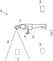
- Fig. 2 illustrates a system 200 according to an embodiment.
- the system 200 comprises the apparatus 100 described earlier.
- the system 200 may also comprise the device 202 that is configured to render the stimulus.
- the device 202 configured to render the stimulus may be any type of device.
- the device 202 configured to render the stimulus may be an appliance (e.g. a home appliance, such as a sound and/or television system, a kitchen appliance, a coffee machine, a washing machine, or any other type of appliance), a medical device, an automotive device, a security device, a signage device, or any other type of device.
- a home appliance such as a sound and/or television system, a kitchen appliance, a coffee machine, a washing machine, or any other type of appliance
- a medical device e.g. a home appliance, such as a sound and/or television system, a kitchen appliance, a coffee machine, a washing machine, or any other type of appliance
- a medical device e.g. a home appliance, such as
- the stimulus referred to herein can be any stimulus suitable to cause a reaction of the user 204.
- the stimulus can comprise any one or more of a heat stimulus, a pain stimulus, a tactile or haptic stimulus (e.g. a vibration), an audio stimulus, a visual stimulus (e.g. any one or more of a light, a color, an image, a spray of droplets, or any other visual stimulus, or any combination of visual stimuli), or any other stimulus, or any combination of stimuli.
- the heat or pain stimulus may be provided by way of a red or infra-red light beam.
- the red or infra-red light beam may, for example, be generated by a laser.
- the red or infra-red light beam may be focused.
- the audio stimulus may be provided by a speaker.
- the visual stimulus may comprise a (e.g. short) flash of light, a flash of a picture (e.g. of a loved one, a funny picture, or any other picture).
- the visual stimulus may be provided by way of a light emitting diode (LED), a light beam, or similar.
- the light beam may be focused. This can enhance the brightness of the visual stimulus, which can cause the magnitude of the reaction of the user 204 to increase.
- a field of view 206 of the user 204 is also illustrated in Fig. 2 .
- the stimulus comprises a visual stimulus
- a determination that the physiological characteristic signal is indicative of a reaction of the user 204 to the visual stimulus rendered by the device 202 means that the device 202 is in the field of view 206 of the user 204.
- a determination that the physiological characteristic signal is not indicative of a reaction of the user 204 to the visual stimulus rendered by the device 202 means that the device 202 is outside the field of view 206 of the user 204 (as illustrated in Fig. 2 ).
- a determination that the physiological characteristic signal is indicative of a reaction of the user 204 to the audio stimulus rendered by the device 202 means that the device 202 is in an audio range of the user 204 (that is, a range of the user 204 within which the user 204 can hear the audio stimulus).
- a determination that the physiological characteristic signal is indicative of a reaction of the user 204 to the audio stimulus rendered by the device 202 can provide an indication that the user 204 is near to the device 202 that renders the stimulus or in the same environment (or space) as the device 202 that renders the stimulus.
- a determination that the physiological characteristic signal is not indicative of a reaction of the user 204 to the audio stimulus rendered by the device 202 means that the device 202 is outside the audio range of the user 204.
- a determination that the physiological characteristic signal is indicative of a reaction of the user 204 to a stimulus rendered by a device 202 means that the device 202 is in a range of the user 204 within which the heat or pain stimulus is detectable by the user 204 (e.g. can be felt by the user 204).
- a determination that the physiological characteristic signal is not indicative of a reaction of the user 204 to the heat or pain stimulus rendered by the device 202 means that the device 202 is outside the range of the user 204 within which the heat or pain stimulus is detectable by the user 204.
- a determination that the physiological characteristic signal is indicative of a reaction of the user 204 to the tactile or haptic stimulus rendered by the device 202 means that the device 202 is in (e.g. direct or indirect) contact with the user 204.
- the device 202 may be worn by the user 202 or close to the body of the user 202.
- a determination that the physiological characteristic signal is not indicative of a reaction of the user 204 to the tactile or haptic stimulus rendered by the device 202 means that the device 202 is not in (e.g. direct or indirect) contact with the user 204.
- the stimulus may be a conscious stimulus. That is, the stimulus may be a stimulus that can be perceived by the user 204, such that the user 204 is aware of the stimulus. In other embodiments, the stimulus may be a subliminal (or subconscious) stimulus. Thus, although the stimulus may suitable to cause a reaction of the user 204, the user 204 may themselves be unaware of the stimulus and/or their reaction to the stimulus according to some embodiments. For example, the stimulus may be below a threshold of sensation or consciousness according to some embodiments.
- the stimulus can comprise a sequence of stimuli.
- a duration of the stimulus may be less than or equal to a threshold duration.
- the threshold duration may, for example, be 10 ms according to some embodiments. This can, for example, ensure that the stimulus is a subliminal (or subconscious) stimulus.
- the device 202 can be configured to render the stimulus with an intensity that increases over time. In some embodiments, the stimulus may be rendered by the device 202 at predetermined time intervals.
- the device 202 can be configured to vary the type of stimulus rendered over time.
- one or more properties of the stimulus may be varied over time, such as the duration and/or intensity (or amplitude) of the stimulus, or a different stimulus may be rendered over time (e.g. rendering a new picture each time).
- the stimulus may comprise one or more pulses of stimulus.
- each pulse may have different properties, e.g. any one or more of a different duration and a different intensity (or amplitude).
- the device 202 can be configured to render a plurality of stimuli. In some of these embodiments, techniques may be employed to ensure that the plurality of stimuli do not interfere with each other. For example, the device 202 can be configured to employ time slot allocation (e.g. where the device 202 may be configured to allocate different stimuli to different time slots) or collision detection (e.g. where the device 202 may be configured to detect when two or more stimuli may interference with one another and take measures to avoid such interference, such as by time slot allocation).
- time slot allocation e.g. where the device 202 may be configured to allocate different stimuli to different time slots
- collision detection e.g. where the device 202 may be configured to detect when two or more stimuli may interference with one another and take measures to avoid such interference, such as by time slot allocation.
- the stimulus may be coded with an identity of the device 202 that renders the stimulus.
- the stimulus may be modulated in a manner that is specific to the device 202 that renders the stimulus.
- different devices 202 that render a stimulus can be coded (e.g. modulated) in different ways. In this way, it can be possible for the processor 102 of the apparatus 100 to distinguish between different devices that render a stimulus in the analysis of the physiological characteristic signal.
- the identity of the device 202 that renders the stimulus may be detectable in the physiological characteristic signal.
- the stimulus may comprise different physical spaces (such as different rooms in a house) being illuminated with different colors, e.g. constantly or intermittently.
- a calibration step may be performed that assigns a specific response in the physiological characteristic signal to a particular color.
- the system 200 can also comprise the physiological characteristic sensor 104.
- the apparatus 100 and the physiological characteristic sensor 104 are illustrated as being different (that is, separate from one another) in the embodiment illustrated in Fig. 2 , as mentioned earlier, it will be understood that the apparatus 100 may comprise the physiological characteristic sensor 104 according to other embodiments.
- the physiological characteristic sensor 104 is configured to be worn on a wrist of the body of the user 204.
- the system 200 can further comprise one or more other devices 208, 210.
- Fig. 3 illustrates a method 300 of operating the apparatus 100 described earlier for use with one or more devices 202, 208, 210 according to an embodiment.
- the apparatus 100 comprises a processor 102.
- the method 300 illustrated in Fig. 3 can generally be performed by or under the control of the processor 102.
- the method 300 will now be described with reference to Figs. 2 and 3 .
- a physiological characteristic signal obtained from a user 204 is acquired from a physiological characteristic sensor 104. More specifically, the processor 102 of the apparatus 100 acquires the physiological characteristic signal from the physiological characteristic sensor 104. At block 304 of Fig. 3 , the acquired physiological characteristic signal is analyzed to determine whether the physiological characteristic signal is indicative of a reaction of the user 204 to a stimulus rendered by a device 202. More specifically, the processor 102 of the apparatus 100 analyzes the acquired physiological characteristic signal to determine whether the physiological characteristic signal is indicative of a reaction of the user 204 to the stimulus rendered by the device 202.
- a determination that the physiological characteristic signal is indicative of a reaction of the user 204 to the visual stimulus rendered by the device 202 means that the device 202 is in the field of view 206 of the user 204, whereas a determination that the physiological characteristic signal is not indicative of a reaction of the user 204 to the visual stimulus rendered by the device 202 means that the device 202 is outside the field of view 206 of the user 204.
- a determination that the physiological characteristic signal is indicative of a reaction of the user 204 to the audio stimulus rendered by the device 202 means that the device 202 is in an audio range of the user 204, whereas a determination that the physiological characteristic signal is not indicative of a reaction of the user 204 to the audio stimulus rendered by the device 202 means that the device 202 is outside the audio range of the user 204.
- a determination that the physiological characteristic signal is indicative of a reaction of the user 204 to a stimulus rendered by a device 202 means that the device 202 is in a range of the user 204 within which the heat or pain stimulus is detectable by the user 204, whereas a determination that the physiological characteristic signal is not indicative of a reaction of the user 204 to the heat or pain stimulus rendered by the device 202 means that the device 202 is outside the range of the user 204 within which the heat or pain stimulus is detectable by the user 204.
- a determination that the physiological characteristic signal is indicative of a reaction of the user 204 to the tactile or haptic stimulus rendered by the device 202 means that the device 202 is in contact with the user 204, whereas a determination that the physiological characteristic signal is not indicative of a reaction of the user 204 to the tactile or haptic stimulus rendered by the device 202 means that the device 202 is not in contact with the user 204.
- the reaction of the user 204 to a stimulus rendered by a device 202 can be used to provide an indication of an attentional awareness of the user. For example, if a mild stimulus is unnoticed by the user, an indication may be provided that the attentional awareness of the user is low. This indication can, for example, be useful for automotive or operator use.
- the device 202 that renders the stimulus may be configured to transmit, to the physiological characteristic sensor 104, a request for the physiological characteristic sensor 104 to obtain the physiological characteristic signal from the user 204.
- the request may be transmitted via a communication channel, such as a wireless communication channel (e.g. using Bluetooth or WiFi).
- the request may be transmitted by the device 202 that renders the stimulus prior to rendering the stimulus, at the same time as rendering the stimulus, or after rendering the stimulus.
- the device 202 may trigger the physiological characteristic sensor 104 to obtain the physiological characteristic signal from the user 204. In this way, the rendering of the stimuli and the obtaining of the physiological characteristic signal can be synchronized according to some embodiments.
- the physiological characteristic sensor 104 may obtain the physiological characteristic signal from the user 204 in a time period that begins (e.g. immediately) prior to the rendering of the stimulus and ends (e.g. immediately) after rendering of the stimulus.
- the processor 102 of the apparatus 100 may be configured to determine whether the physiological characteristic signal is indicative of a reaction of the user 204 to the stimulus rendered by the device 202 by being configured to determine whether there is a change in the physiological characteristic signal, e.g. a change in the physiological characteristic signal between a point in time (e.g. immediately) prior to the device 202 rendering the stimulus and a point in time (e.g. immediately) after the device 202 renders the stimulus.
- a change in the physiological characteristic signal e.g. a change in the physiological characteristic signal between a point in time (e.g. immediately) prior to the device 202 rendering the stimulus and a point in time (e.g. immediately) after the device 202 renders the stimulus.
- the processor 102 of the apparatus 100 may be configured to determine that the physiological characteristic signal is indicative of the reaction of the user 204 to the stimulus rendered by the device 202 where it is determined that there is a change in the physiological characteristic signal (or a change in the physiological characteristic signal that is greater than a threshold). Similarly, the processor 102 of the apparatus 100 may be configured to determine that the physiological characteristic signal is not indicative of the reaction of the user 204 to the stimulus rendered by the device 202 where it is determined that there is no change in the physiological characteristic signal (or a change in the physiological characteristic signal that is less than the threshold).
- the threshold may be personal to the user 204.
- the threshold may be set based on the user 204.
- the apparatus 100 can be optimized to account for reactions that may vary between users.
- each user may have a profile that outlines their expected reactions to different stimuli, such that the reactions can be recognized in the physiological characteristic signal when they occur.
- the profile may be adapted or learnt over time.
- a user identification technique may be used to select a profile for the user 204.
- Figs. 4(a) and (b) illustrate example physiological characteristic signals that are indicative of a reaction of a user 204 to a stimulus rendered by a device 202 according to an embodiment.
- Fig. 4(a) illustrates a sympathetic nervous system (SNS) signal acquired in a time period during which the stimulus 500 is rendered by the device 202
- Fig. 4(b) illustrates a skin resistance signal acquired during the time period during which the stimulus 500 is rendered by the device 202.
- SNS sympathetic nervous system
- Fig. 4(b) illustrates a skin resistance signal acquired during the time period during which the stimulus 500 is rendered by the device 202.
- an increase in the sympathetic nervous system signal that is more than a predefined threshold is indicative of the reaction of the user 204 to the stimulus 500 rendered by the device 202.
- the predefined threshold in this example may, for example, be set based on an average increase in the sympathetic nervous system signal detected in the absence of the stimulus 500. As illustrated in Fig. 4(b) , a decrease in the skin resistance signal that is more than a predefined threshold is indicative of the reaction of the user 204 to the stimulus 500 rendered by the device 202. The predefined threshold in this example may, for example, be set based on an average decrease in the skin resistance signal detected in the absence of the stimulus 500.
- a manner in which one or more devices 202, 208, 210 operate is controlled based on whether the user 204 reacted to the stimulus rendered by the device 202. More specifically, the processor 102 of the apparatus 100 controls the manner in which the one or more devices 202, 208, 210 operate based on whether the user 204 reacted to the stimulus rendered by the device 202. In some embodiments, the manner in which one or more devices 202, 208, 210 operate can comprise a manner in which one or more devices 202, 208 render information.
- the processor 102 of the apparatus 100 can be configured to control the device 202 to render visual information if the user 204 reacted to a visual stimulus rendered by the device 202. That is, the processor 102 of the apparatus 100 can be configured to control the device 202 that renders the visual stimulus to render visual information if the user 204 reacts to the visual stimulus rendered by that device 202. In this way, it can be ensured that the visual information rendered by the device 202 will be seen by the user 204.
- the processor 102 can be configured to control the device 202 to render audio information if the user 204 failed to react to the visual stimulus rendered by the device 202. That is, the processor 102 can be configured to control the device 202 that renders the visual stimulus to render audio information if the user 204 fails to react to the visual stimulus rendered by that device 202. In this way, while the user 204 is unable to observe visual information rendered by the device 202 that renders the stimulus, it can be ensured that information rendered by that device 202 can still be communicated to the user by instead rendering the information as audio information.
- the processor 102 can be configured to control one or more devices 208 that the user 204 is wearing or holding to render visual information if the user 204 failed to react to the visual stimulus rendered by the device 202. That is, the processor 102 can be configured to control one or more devices 208 other than the device 202 that renders the stimulus to render visual information if the user 204 fails to react to the visual stimulus rendered by the device 202 that renders the visual stimulus. As a device 208 that the user is wearing or holding is likely to be in the field of view 206 of the user 204, the chance of the visual information being successfully communicated to the user 204 can be improved.
- the processor 102 can be configured to control one or more devices 210 in the field of view 206 of the user 204 to render visual information if the user 204 failed to react to the visual stimulus rendered by the device 202. That is, the processor 102 can be configured to control one or more devices 210 other than the device 202 that renders the stimulus to render visual information if the user 204 fails to react to the visual stimulus rendered by the device 202 that renders the visual stimulus. As the one or more devices 210 that are controlled to render the visual information are in the field of view 206 of the user 204, it can be ensured that the visual information can still be communicated to the user 204 even when the user 204 is unable to observe visual information rendered by the device 202 that rendered the visual stimulus.
- each of the one or more devices 210 may comprise a proximity sensor, which can acquire information on the proximity of the user 204 to the device 210 for use in selecting which of the one or more devices 210 to control to render the visual information.
- the processor 102 of the apparatus 100 may be configured to, if the physiological characteristic signal is indicative of a reaction of the user 204 to a stimulus rendered by a device 202 (at block 304 of Fig. 3 ), analyze the acquired physiological characteristic signal to determine an intensity of the stimulus. For example, a change in the acquired physiological characteristic signal may be proportional to the perceived light intensity.
- the determined intensity of the stimulus may be indicative of a location of the device 202 with respect to the user 204 (e.g. with respect to a center of the field of view 206 of the user 204 according to embodiments involving a visual stimulus).
- the higher the determined intensity of the stimulus the closer the device 202 may be to the user 204 (e.g. to the center of the field of view 206 of the user 204 according to embodiments involving a visual stimulus, rather than in the peripheral vision of the user 204).
- the lower the determined intensity of the stimulus the further the device 202 may be from the user 204 (e.g. from the center of the field of view 206 of the user 204 according to embodiments involving a visual stimulus).
- the determined intensity of the stimulus may be indicative of a distance of the user 204 from the device 202.
- a point at which the physiological characteristic signal is indicative of the reaction of the user 204 to the stimulus may be indicative of a distance of the user 204 from the device 202 that renders the stimulus.
- the processor 102 of the apparatus 100 may be configured to analyze the acquired physiological characteristic signal to determine whether the user 204 is facing or partially facing the device 202. For example, this determination may be based on the determined location of the device 202 with respect to a center of the field of view 206 of the user 204.
- the physiological characteristic signal comprises a brain activity (e.g. an EEG) sensor
- the processor 102 of the apparatus 100 may be configured to analyze the acquired brain activity signal to determine if a visual stimulus is received by a left eye of the user 204, a right of the user 204, or both eyes of the user 204.
- the processor 102 of the apparatus 100 may be configured to, if the physiological characteristic signal is indicative of a reaction of the user 204 to a stimulus rendered by a device 202, analyze the acquired physiological characteristic signal to determine a property of the stimulus.
- the property of the stimulus may be indicative of a location of the user 204 in an environment.
- the processor 102 of the apparatus 100 may be configured to analyze the acquired physiological characteristic signal to determine in which physical space the user 204 is present, e.g. based on the specific responses previously assigned to a particular color in a calibration step.
- Fig. 5 illustrates an example of the method 300 of Fig. 3 performed in the system 200 of Fig. 2 according to an embodiment.
- the device 202 configured to render the stimulus may need to communicate information to the user 204.
- the device 202 may render a stimulus, e.g. in any of the manners described earlier.
- the device 202 that renders the stimulus may transmit, to the physiological characteristic sensor 104, a request for the physiological characteristic sensor 104 to obtain the physiological characteristic signal from the user 204.
- this request may be transmitted by the device 202 that renders the stimulus prior to rendering the stimulus, at the same time as rendering the stimulus, or after rendering the stimulus.
- the physiological characteristic sensor 104 may obtain a physiological characteristic signal from the user 204.
- the method 300 described earlier with reference to Fig. 3 is performed by the apparatus 100 or, more specifically, by the processor 102 of the apparatus 100. That is, at block 410 of Fig. 5 , as described in more detail earlier with reference to Fig. 3 , the processor 102 of the apparatus 100 acquires the physiological characteristic signal from the physiological characteristic sensor 104 (block 302 of Fig. 3 ), analyzes the acquired physiological characteristic signal to determine whether the physiological characteristic signal is indicative of a reaction of the user 204 to the stimulus rendered by the device 202 (block 304 of Fig. 3 ), and controls a manner in which one or more devices 202, 208, 210 operate based on whether the user 204 reacted to the stimulus rendered by the device 202 (block 306 of Fig. 3 ).
- the processor 102 of the apparatus 100 may control the device 202 that renders the stimulus to render visual information.
- the processor 102 of the apparatus 100 may control the device 202 that renders the stimulus to render audio information.
- the processor 102 of the apparatus 100 may control one or more other devices to render visual information, such as one or more devices 208 that the user 204 is wearing or holding (as illustrated in Fig. 5 ) and/or one or more devices in the field of view 206 of the user 204 to render visual information (not illustrated in Fig. 5 ).
- the processor 102 of the apparatus 100 may be configured to output information or feedback to the user 204.
- This information or feedback may, for example, depend on the reaction of the user indicated in the physiological characteristic signal.
- a brightness of a light may be adapted (e.g. to facilitate reading and/or attract the attention of the user 204), visual notifications or information may be provided via or at least supported by audio, information may be routed to a wearable device or another device that is within the peripheral vision of the user, or similar.
- the processor 102 of the apparatus 100 may be configured to detect whether the user 204 is looking at (e.g. a screen of) the device 202.
- the processor 102 of the apparatus 100 may be configured to determine that the user 204 has closed their eyes and/or fallen asleep. For example, this may be useful in detecting whether a user has fallen asleep while watching television or has closed their eyes or is falling asleep in a car at night (e.g. where there is no reaction to street lights anymore).
- a computer program product comprising a computer readable medium.
- the computer readable medium has computer readable code embodied therein.
- the computer readable code is configured such that, on execution by a suitable computer or processor, the computer or processor is caused to perform the method described herein.
- the computer readable medium may be, for example, any entity or device capable of carrying the computer program product.
- the computer readable medium may include a data storage, such as a ROM (such as a CD-ROM or a semiconductor ROM) or a magnetic recording medium (such as a hard disk).
- the computer readable medium may be a transmissible carrier, such as an electric or optical signal, which may be conveyed via electric or optical cable or by radio or other means.
- the computer readable medium may be constituted by such a cable or other device or means.
- the computer readable medium may be an integrated circuit in which the computer program product is embedded, the integrated circuit being adapted to perform, or used in the performance of, the method described herein.
- a computer program may be stored or distributed on a suitable medium, such as an optical storage medium or a solid-state medium supplied together with or as part of other hardware, but may also be distributed in other forms, such as via the Internet or other wired or wireless telecommunication systems. Any reference signs in the claims should not be construed as limiting the scope.
Landscapes
- Engineering & Computer Science (AREA)
- General Engineering & Computer Science (AREA)
- Theoretical Computer Science (AREA)
- Human Computer Interaction (AREA)
- Physics & Mathematics (AREA)
- General Physics & Mathematics (AREA)
- Measurement Of The Respiration, Hearing Ability, Form, And Blood Characteristics Of Living Organisms (AREA)
Priority Applications (2)
| Application Number | Priority Date | Filing Date | Title |
|---|---|---|---|
| EP18191361.7A EP3617847A1 (de) | 2018-08-29 | 2018-08-29 | Steuerung des betriebs einer oder mehrerer vorrichtungen |
| PCT/EP2019/073027 WO2020043807A1 (en) | 2018-08-29 | 2019-08-29 | Controlling the operation of one or more devices |
Applications Claiming Priority (1)
| Application Number | Priority Date | Filing Date | Title |
|---|---|---|---|
| EP18191361.7A EP3617847A1 (de) | 2018-08-29 | 2018-08-29 | Steuerung des betriebs einer oder mehrerer vorrichtungen |
Publications (1)
| Publication Number | Publication Date |
|---|---|
| EP3617847A1 true EP3617847A1 (de) | 2020-03-04 |
Family
ID=63682961
Family Applications (1)
| Application Number | Title | Priority Date | Filing Date |
|---|---|---|---|
| EP18191361.7A Withdrawn EP3617847A1 (de) | 2018-08-29 | 2018-08-29 | Steuerung des betriebs einer oder mehrerer vorrichtungen |
Country Status (2)
| Country | Link |
|---|---|
| EP (1) | EP3617847A1 (de) |
| WO (1) | WO2020043807A1 (de) |
Citations (4)
| Publication number | Priority date | Publication date | Assignee | Title |
|---|---|---|---|---|
| US20110105937A1 (en) * | 2009-10-29 | 2011-05-05 | Neurofocus, Inc. | Analysis of controlled and automatic attention for introduction of stimulus material |
| US20140316191A1 (en) * | 2013-04-17 | 2014-10-23 | Sri International | Biofeedback Virtual Reality Sleep Assistant |
| US20170346817A1 (en) * | 2016-05-31 | 2017-11-30 | John C. Gordon | Authentication based on gaze and physiological response to stimuli |
| US20180024626A1 (en) * | 2016-07-21 | 2018-01-25 | Magic Leap, Inc. | Technique for controlling virtual image generation system using emotional states of user |
-
2018
- 2018-08-29 EP EP18191361.7A patent/EP3617847A1/de not_active Withdrawn
-
2019
- 2019-08-29 WO PCT/EP2019/073027 patent/WO2020043807A1/en not_active Ceased
Patent Citations (4)
| Publication number | Priority date | Publication date | Assignee | Title |
|---|---|---|---|---|
| US20110105937A1 (en) * | 2009-10-29 | 2011-05-05 | Neurofocus, Inc. | Analysis of controlled and automatic attention for introduction of stimulus material |
| US20140316191A1 (en) * | 2013-04-17 | 2014-10-23 | Sri International | Biofeedback Virtual Reality Sleep Assistant |
| US20170346817A1 (en) * | 2016-05-31 | 2017-11-30 | John C. Gordon | Authentication based on gaze and physiological response to stimuli |
| US20180024626A1 (en) * | 2016-07-21 | 2018-01-25 | Magic Leap, Inc. | Technique for controlling virtual image generation system using emotional states of user |
Also Published As
| Publication number | Publication date |
|---|---|
| WO2020043807A1 (en) | 2020-03-05 |
Similar Documents
| Publication | Publication Date | Title |
|---|---|---|
| KR102820566B1 (ko) | 뇌-컴퓨터 인터페이스 | |
| JP2017535388A (ja) | 感情状態を伝えるためのモジュラウェアラブルデバイス | |
| KR102314644B1 (ko) | 주변 디바이스의 정보를 제공하는 시스템 및 방법 | |
| US8655441B2 (en) | Methods and apparatus for monitoring patients and delivering therapeutic stimuli | |
| CN106303009A (zh) | 使用用于控制用户警报的生物信号 | |
| US10936060B2 (en) | System and method for using gaze control to control electronic switches and machinery | |
| US20230026513A1 (en) | Human interface device | |
| US20220189626A1 (en) | Systems and methods for detecting and addressing quality issues in remote therapy sessions | |
| US20250362753A1 (en) | Brain-computer interface | |
| KR20190006670A (ko) | 동영상 기반 발작 추적감시 방법 및 장치 | |
| JP2023129585A (ja) | 情報処理方法、情報処理装置、及び情報処理プログラム | |
| JP7599758B2 (ja) | 情報処理方法 | |
| WO2008145957A2 (en) | Inter-active systems | |
| WO2020043807A1 (en) | Controlling the operation of one or more devices | |
| CN106096220B (zh) | 一种穴位信息展示方法、相关设备及系统 | |
| CN112925408A (zh) | 信息处理装置及计算机可读介质 | |
| JP7343168B2 (ja) | 情報処理装置、プログラム、及び、方法 | |
| WO2018215253A1 (en) | An apparatus and method for providing feedback to a participant of a communication | |
| KR102564202B1 (ko) | 사용자의 스트레스 완화를 위해 상호작용하는 가상동물을 제공하는 전자장치 및 이의 제어방법 | |
| US20210165488A1 (en) | Information processing apparatus and non-transitory computer readable medium | |
| WO2025094977A1 (ja) | 脳波誘発システム、非言語コミュニケーションシステム、脳波誘発プログラム、非言語コミュニケーションプログラム | |
| WO2022125510A1 (en) | Systems and methods for detecting and addressing quality issues in remote therapy sessions | |
| WO2023139001A1 (en) | A brain control interface system for controlling a controllable device | |
| EP3415079A1 (de) | Vorrichtung zur aufnahme einer eingabe, die eine oder mehrere symptome einer person anzeigt, und verfahren zum betrieb davon |
Legal Events
| Date | Code | Title | Description |
|---|---|---|---|
| PUAI | Public reference made under article 153(3) epc to a published international application that has entered the european phase |
Free format text: ORIGINAL CODE: 0009012 |
|
| AK | Designated contracting states |
Kind code of ref document: A1 Designated state(s): AL AT BE BG CH CY CZ DE DK EE ES FI FR GB GR HR HU IE IS IT LI LT LU LV MC MK MT NL NO PL PT RO RS SE SI SK SM TR |
|
| AX | Request for extension of the european patent |
Extension state: BA ME |
|
| RAP1 | Party data changed (applicant data changed or rights of an application transferred) |
Owner name: KONINKLIJKE PHILIPS N.V. |
|
| STAA | Information on the status of an ep patent application or granted ep patent |
Free format text: STATUS: THE APPLICATION IS DEEMED TO BE WITHDRAWN |
|
| 18D | Application deemed to be withdrawn |
Effective date: 20200905 |