EP3617878B1 - Datenverarbeitungssystem, datenverarbeitungsvorrichtung und datenverarbeitungsprogramm - Google Patents
Datenverarbeitungssystem, datenverarbeitungsvorrichtung und datenverarbeitungsprogramm Download PDFInfo
- Publication number
- EP3617878B1 EP3617878B1 EP17911177.8A EP17911177A EP3617878B1 EP 3617878 B1 EP3617878 B1 EP 3617878B1 EP 17911177 A EP17911177 A EP 17911177A EP 3617878 B1 EP3617878 B1 EP 3617878B1
- Authority
- EP
- European Patent Office
- Prior art keywords
- data
- amount
- unit
- vehicle
- resources
- Prior art date
- Legal status (The legal status is an assumption and is not a legal conclusion. Google has not performed a legal analysis and makes no representation as to the accuracy of the status listed.)
- Active
Links
Images


Classifications
-
- B—PERFORMING OPERATIONS; TRANSPORTING
- B60—VEHICLES IN GENERAL
- B60H—ARRANGEMENTS OF HEATING, COOLING, VENTILATING OR OTHER AIR-TREATING DEVICES SPECIALLY ADAPTED FOR PASSENGER OR GOODS SPACES OF VEHICLES
- B60H1/00—Heating, cooling or ventilating devices
- B60H1/00642—Control systems or circuits; Control members or indication devices for heating, cooling or ventilating devices
- B60H1/00735—Control systems or circuits characterised by their input, i.e. by the detection, measurement or calculation of particular conditions, e.g. signal treatment, dynamic models
- B60H1/00764—Control systems or circuits characterised by their input, i.e. by the detection, measurement or calculation of particular conditions, e.g. signal treatment, dynamic models the input being a vehicle driving condition, e.g. speed
- B60H1/00771—Control systems or circuits characterised by their input, i.e. by the detection, measurement or calculation of particular conditions, e.g. signal treatment, dynamic models the input being a vehicle driving condition, e.g. speed the input being a vehicle position or surrounding, e.g. GPS-based position or tunnel
-
- B—PERFORMING OPERATIONS; TRANSPORTING
- B60—VEHICLES IN GENERAL
- B60H—ARRANGEMENTS OF HEATING, COOLING, VENTILATING OR OTHER AIR-TREATING DEVICES SPECIALLY ADAPTED FOR PASSENGER OR GOODS SPACES OF VEHICLES
- B60H1/00—Heating, cooling or ventilating devices
- B60H1/00357—Air-conditioning arrangements specially adapted for particular vehicles
- B60H1/00371—Air-conditioning arrangements specially adapted for particular vehicles for vehicles carrying large numbers of passengers, e.g. buses
-
- G—PHYSICS
- G06—COMPUTING OR CALCULATING; COUNTING
- G06F—ELECTRIC DIGITAL DATA PROCESSING
- G06F9/00—Arrangements for program control, e.g. control units
- G06F9/06—Arrangements for program control, e.g. control units using stored programs, i.e. using an internal store of processing equipment to receive or retain programs
- G06F9/46—Multiprogramming arrangements
- G06F9/50—Allocation of resources, e.g. of the central processing unit [CPU]
- G06F9/5005—Allocation of resources, e.g. of the central processing unit [CPU] to service a request
- G06F9/5027—Allocation of resources, e.g. of the central processing unit [CPU] to service a request the resource being a machine, e.g. CPUs, Servers, Terminals
- G06F9/505—Allocation of resources, e.g. of the central processing unit [CPU] to service a request the resource being a machine, e.g. CPUs, Servers, Terminals considering the load
-
- G—PHYSICS
- G08—SIGNALLING
- G08C—TRANSMISSION SYSTEMS FOR MEASURED VALUES, CONTROL OR SIMILAR SIGNALS
- G08C17/00—Arrangements for transmitting signals characterised by the use of a wireless electrical link
-
- H—ELECTRICITY
- H04—ELECTRIC COMMUNICATION TECHNIQUE
- H04L—TRANSMISSION OF DIGITAL INFORMATION, e.g. TELEGRAPHIC COMMUNICATION
- H04L43/00—Arrangements for monitoring or testing data switching networks
- H04L43/04—Processing captured monitoring data, e.g. for logfile generation
-
- H—ELECTRICITY
- H04—ELECTRIC COMMUNICATION TECHNIQUE
- H04L—TRANSMISSION OF DIGITAL INFORMATION, e.g. TELEGRAPHIC COMMUNICATION
- H04L43/00—Arrangements for monitoring or testing data switching networks
- H04L43/08—Monitoring or testing based on specific metrics, e.g. QoS, energy consumption or environmental parameters
- H04L43/0876—Network utilisation, e.g. volume of load or congestion level
-
- H—ELECTRICITY
- H04—ELECTRIC COMMUNICATION TECHNIQUE
- H04L—TRANSMISSION OF DIGITAL INFORMATION, e.g. TELEGRAPHIC COMMUNICATION
- H04L47/00—Traffic control in data switching networks
- H04L47/70—Admission control; Resource allocation
- H04L47/72—Admission control; Resource allocation using reservation actions during connection setup
- H04L47/724—Admission control; Resource allocation using reservation actions during connection setup at intermediate nodes, e.g. resource reservation protocol [RSVP]
-
- H—ELECTRICITY
- H04—ELECTRIC COMMUNICATION TECHNIQUE
- H04L—TRANSMISSION OF DIGITAL INFORMATION, e.g. TELEGRAPHIC COMMUNICATION
- H04L47/00—Traffic control in data switching networks
- H04L47/70—Admission control; Resource allocation
- H04L47/76—Admission control; Resource allocation using dynamic resource allocation, e.g. in-call renegotiation requested by the user or requested by the network in response to changing network conditions
- H04L47/762—Admission control; Resource allocation using dynamic resource allocation, e.g. in-call renegotiation requested by the user or requested by the network in response to changing network conditions triggered by the network
-
- H—ELECTRICITY
- H04—ELECTRIC COMMUNICATION TECHNIQUE
- H04L—TRANSMISSION OF DIGITAL INFORMATION, e.g. TELEGRAPHIC COMMUNICATION
- H04L67/00—Network arrangements or protocols for supporting network services or applications
- H04L67/01—Protocols
- H04L67/12—Protocols specially adapted for proprietary or special-purpose networking environments, e.g. medical networks, sensor networks, networks in vehicles or remote metering networks
- H04L67/125—Protocols specially adapted for proprietary or special-purpose networking environments, e.g. medical networks, sensor networks, networks in vehicles or remote metering networks involving control of end-device applications over a network
-
- B—PERFORMING OPERATIONS; TRANSPORTING
- B60—VEHICLES IN GENERAL
- B60Y—INDEXING SCHEME RELATING TO ASPECTS CROSS-CUTTING VEHICLE TECHNOLOGY
- B60Y2200/00—Type of vehicle
- B60Y2200/30—Railway vehicles
Definitions
- the present invention relates to a technology for performing data processing while adjusting the amount of resources to be used for the data processing in the amount of resources of computer resources.
- a railroad operator and a vehicle appliance manufacturer acquire, accumulate and analyze operation data of an appliance to detect a sign of a failure of the appliance.
- a corporation aiming at data utilization uses a public cloud as an infrastructure for collecting data.
- a public cloud enables adjustment of the amount of computer resources.
- the amount of operation data changes depending on the state of an appliance mounted in a vehicle.
- the amount of resources necessary to process the operation data in the public cloud changes over time.
- Patent Literature 1 discloses a technology for adjusting the amount of resources used in the public cloud.
- US 2013/007753 A1 discloses an elastic scaling cloud-hosted batch application system and method that performs automated elastic scaling of the number of compute instances used to process batch applications in a cloud computing environment.
- the system and method use automated elastic scaling to minimize job completion time and monetary cost of resources.
- Examples of the system and method use a workload-driven approach to estimate a work volume to be performed. This is based on task arrivals and job execution times.
- an adaptive controller dynamically adapts the number of compute instances to minimize the cost and completion time. Examples of the system and method also mitigate startup delays by computing a work volume in the near future and gradually starting up additional compute instances before they are needed.
- a computer system accesses information specifying a target operational metric that is to be maintained on a plurality of cloud resources.
- the computer system determines a current measured value for the target operational metric for at least some of the cloud resources.
- the computer system further calculates a scaling factor based on the target operational metric and the current measured value, where the scaling factor represents an amount of variance between the target operational metric and the current measured value.
- the computer system also calculates a delta value representing a modified quantity of cloud resources modified by the calculated scaling factor and determines whether a scaling action is to occur based on the calculated delta value.
- JP2016185730 relates to a method for optimising the amount of sensor data (for example, airconditioners) collected onboard a vehicle, such as a train, by making the number of sampling points dependent on device state. The data is then processed by an external data processing system.
- sensor data for example, airconditioners
- Patent Literature 1 JP 2015-87935 A
- a railroad operator and a vehicle appliance manufacturer install a sensor in an appliance to be mounted in a vehicle, and monitor the state of the appliance by using the sensor.
- the amount of data that is transmitted to a public cloud changes depending on the degradation state of the appliance.
- Patent Literature 1 In a case where the technology disclosed in Patent Literature 1 is applied to a railroad service, a user of the public cloud secures necessary computer resources by notifying of the necessary amount of resources before transmitting operation data to the public cloud.
- the public cloud cannot secure the necessary computer resources before the operation data is transmitted. Accordingly, because the operation data is transmitted before the computer resources are secured, computer resources necessary to process the operation data may possibly become insufficient.
- the present invention has its object to enable data processing to be performed by securing just the necessary amount of resources.
- data processing can be performed by securing just the necessary amount of resources.
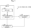
- FIG. 1 A configuration of a data processing system 100 will be described with reference to Fig. 1 .
- the data processing system 100 includes one or more appliances 200.
- the data processing system 100 further includes a vehicle monitoring apparatus 300, a travel management apparatus 400, and a data processing apparatus 500.
- the one or more appliances 200 and the vehicle monitoring apparatus 300 are mounted in a vehicle 110.
- the vehicle 110 is a railroad vehicle.
- the appliance 200 is an air conditioner.
- the vehicle monitoring apparatus 300 monitors an operation state of each appliance 200, and a travel state of the vehicle 110.
- the travel management apparatus 400 manages a travel schedule of the vehicle 110.
- the data processing apparatus 500 processes data that is acquired by each appliance 200.
- a configuration of the appliance 200 will be described with reference to Fig. 2 .
- the appliance 200 is a computer including pieces of hardware such as a processor 201, a memory 202, a sensor 203, and a communication interface 204. These pieces of hardware are interconnected by a signal line.
- the processor 201 is an integrated circuit (IC) that performs arithmetic processing, and controls other hardware.
- the processor 201 is a central processing unit (CPU).
- the memory 202 is a volatile or non-volatile storage device.
- the memory 202 is also referred to as a main storage device or a main memory.
- the memory 202 is a random access memory (RAM).
- the sensor 203 is a device that performs measurement.
- the sensor 203 is a temperature sensor.
- the communication interface 204 is an interface to which a communication device is connected.
- the communication device includes a receiver and a transmitter.
- the appliance 200 includes software elements such as a diagnosis unit 212 and an operation data amount determination unit 213.
- the software elements are elements that are implemented by software.
- Appliance programs for causing the computer to function as the diagnosis unit 212 and the operation data amount determination unit 213 are stored in the memory 202.
- the appliance programs are executed by the processor 201.
- An operating system is further stored in the memory 202.
- the OS is executed by the processor 201.
- the processor 201 executes the appliance program while executing the OS.
- Data that is obtained by executing the appliance program is stored in a storage device such as the memory 202, a register in the processor 201, or a cache memory in the processor 201.
- the sensor 203 functions as a measurement data acquisition unit 211.
- the communication interface 204 functions as an operation data transmission unit 214.
- the appliance 200 may include a plurality of processors instead of the processor 201.
- the plurality of processors share a role of the processor 201.
- the appliance program may be recorded in a non-volatile recording medium such as an optical disk or a flash memory in a computer-readable manner.
- a configuration of the vehicle monitoring apparatus 300 will be described with reference to Fig. 3 .
- the vehicle monitoring apparatus 300 is a computer including pieces of hardware such as a processor 301, a memory 302, an auxiliary storage device 303, and a communication interface 304. These pieces of hardware are interconnected by a signal line.
- the processor 301 is an IC that performs arithmetic processing, and controls other hardware.
- the processor 301 is a CPU.
- the memory 302 is a volatile storage device.
- the memory 302 is also referred to as a main storage device or a main memory.
- the memory 302 is a RAM. Data stored in the memory 302 is saved in the auxiliary storage device 303 as necessary.
- the auxiliary storage device 303 is a non-volatile storage device.
- the auxiliary storage device 303 is a read only memory (ROM), a hard disk drive (HDD), or a flash memory. Data stored in the auxiliary storage device 303 is loaded into the memory 302 as necessary.
- the communication interface 304 is an interface to which a communication device is connected.
- the vehicle monitoring apparatus 300 includes software elements such as an aggregation unit 312, a load monitoring unit 313, and a travel state acquisition unit 321.
- the software elements are elements that are implemented by software.
- Vehicle monitoring programs for causing the computer to function as the aggregation unit 312, the load monitoring unit 313, and the travel state acquisition unit 321 are stored in the auxiliary storage device 303.
- the vehicle monitoring programs are loaded into the memory 302, and are executed by the processor 301.
- An OS is further stored in the auxiliary storage device 303. At least a part of the OS is loaded into the memory 302, and is executed by the processor 301.
- the processor 301 executes the vehicle monitoring program while executing the OS.
- Data that is obtained by executing the vehicle monitoring program is stored in a storage device such as the memory 302, the auxiliary storage device 303, a register in the processor 301, or a cache memory in the processor 301.
- the communication interface 304 functions as an operation data reception unit 311, a transmission data transmission unit 314, and a travel state transmission unit 322.
- the vehicle monitoring apparatus 300 may include a plurality of processors instead of the processor 301.
- the plurality of processors share a role of the processor 301.
- the vehicle monitoring program may be recorded in a non-volatile recording medium such as a magnetic disk, an optical disk, or a flash memory in a computer-readable manner.
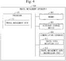
- a configuration of the travel management apparatus 400 will be described with reference to Fig. 4 .
- the travel management apparatus 400 is a computer including pieces of hardware such as a processor 401, a memory 402, an auxiliary storage device 403, and a communication interface 404. These pieces of hardware are interconnected by a signal line.
- the processor 401 is an IC that performs arithmetic processing, and controls other hardware.
- the processor 401 is a CPU.
- the memory 402 is a volatile storage device.
- the memory 402 is also referred to as a main storage device or a main memory.
- the memory 402 is a RAM. Data stored in the memory 402 is saved in the auxiliary storage device 403 as necessary.
- the auxiliary storage device 403 is a non-volatile storage device.
- the auxiliary storage device 403 is a ROM, an HDD, or a flash memory. Data stored in the auxiliary storage device 403 is loaded into the memory 402 as necessary.
- the communication interface 404 is an interface to which a communication device is connected.
- the travel management apparatus 400 includes software elements such as a travel management unit 412.
- the software elements are elements that are implemented by software.
- a travel management program for causing the computer to function as the travel management unit 412 is stored in the auxiliary storage device 403.
- the travel management program is loaded into the memory 402, and is executed by the processor 401.
- An OS is further stored in the auxiliary storage device 403. At least a part of the OS is loaded into the memory 402, and is executed by the processor 401.
- the processor 401 executes the travel management program while executing the OS.
- Data that is obtained by executing the travel management program is stored in a storage device such as the memory 402, the auxiliary storage device 403, a register in the processor 401, or a cache memory in the processor 401.
- the communication interface 404 functions as a travel state reception unit 411 and a travel management data transmission unit 413.
- the travel management apparatus 400 may include a plurality of processors instead of the processor 401.
- the plurality of processors share a role of the processor 401.
- the travel management program may be recorded in a non-volatile recording medium such as a magnetic disk, an optical disk, or a flash memory in a computer-readable manner.
- a configuration of the data processing apparatus 500 will be described with reference to Fig. 5 .
- the data processing apparatus 500 is a computer including pieces of hardware such as a processor 501, a memory 502, an auxiliary storage device 503, and a communication interface 504. These pieces of hardware are interconnected by a signal line.
- the processor 501 is an IC that performs arithmetic processing, and controls other hardware.
- the processor 501 is a CPU.
- the memory 502 is a volatile storage device.
- the memory 502 is also referred to as a main storage device or a main memory.
- the memory 502 is a RAM. Data stored in the memory 502 is saved in the auxiliary storage device 503 as necessary.
- the auxiliary storage device 503 is a non-volatile storage device.
- the auxiliary storage device 503 is a ROM, an HDD, or a flash memory. Data stored in the auxiliary storage device 503 is loaded into the memory 502 as necessary.
- the communication interface 504 is an interface to which a communication device is connected.
- the data processing apparatus 500 includes software elements such as a resource amount calculation unit 512, a resource amount adjustment unit 513, a data processing unit 514, and a vehicle management unit 522.
- the software elements are elements that are implemented by software.
- Data processing programs for causing the computer to function as the resource amount calculation unit 512, the resource amount adjustment unit 513, the data processing unit 514, and the vehicle management unit 522 are stored in the auxiliary storage device 503.
- the data processing programs are loaded into the memory 502, and are executed by the processor 501.
- An OS is further stored in the auxiliary storage device 503. At least a part of the OS is loaded into the memory 502, and is executed by the processor 501.
- the processor 501 executes the data processing program while executing the OS.
- Data that is obtained by executing the data processing program is stored in a storage device such as the memory 502, the auxiliary storage device 503, a register in the processor 501, or a cache memory in the processor 501.
- the communication interface 504 functions as a transmission data reception unit 511 and a travel management data reception unit 521.
- the data processing apparatus 500 may include a plurality of processors instead of the processor 501.
- the plurality of processors share a role of the processor 501.
- the data processing program may be recorded in a non-volatile recording medium such as a magnetic disk, an optical disk, or a flash memory in a computer-readable manner.
- An operation of the data processing system 100 corresponds to a data processing method. Furthermore, a procedure of the data processing method by the data processing apparatus 500 corresponds to a procedure of the data processing program.
- step S201 the measurement data acquisition unit 211 acquires measurement data 291 every unit time.
- the measurement data acquisition unit 211 performs measurement and generates the measurement data 291.
- the measurement data 291 includes a measurement value.
- the measurement value is a value that is obtained by measurement.
- the measurement value is a temperature.
- the unit time is 100 milliseconds.
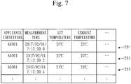
- the measurement data 291 for a case where the appliance 200 is an air conditioner will be described with reference to Fig. 7 .
- the measurement data 291 includes an appliance identifier, a measurement time, and a set temperature (set value).
- the measurement data 291 further includes a measurement value such as an exhaust temperature.
- the appliance identifier is an identifier for identifying the appliance 200.
- the measurement time is a time when measurement is performed.
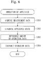
- step S202 a description will be given from step S202.
- the diagnosis unit 212 diagnoses an appliance state on the basis of the measurement data 291.
- the appliance state is a state of the appliance 200.
- the appliance state is a state of degradation of the appliance 200.
- the diagnosis unit 212 performs diagnosis in the following manner.
- the measurement data 291 is assumed to include the set temperature and the exhaust temperature.
- the diagnosis unit 212 calculates a difference between the set temperature and the exhaust temperature.
- the calculated difference will be referred to as a temperature difference.
- the diagnosis unit 212 determines the state of degradation of the appliance 200 on the basis of the temperature difference. The greater the temperature difference, the more degraded the appliance 200 is.
- the diagnosis unit 212 determines the state of degradation of the appliance 200 in the following manner. Determination standards are determined in advance.
- the diagnosis unit 212 determines that the appliance 200 is normal.
- the diagnosis unit 212 determines that the appliance 200 is somewhat degraded.
- the diagnosis unit 212 determines that the appliance 200 is degraded.
- step S203 the operation data amount determination unit 213 determines the amount of operation data on the basis of the appliance state.
- the amount of operation data is a volume of the operation data.
- the operation data is measurement data to be transmitted to the vehicle monitoring apparatus 300.
- the operation data amount determination unit 213 determines the amount of operation data in the following manner. Determination standards are determined in advance.
- the operation data amount determination unit 213 determines the amount of operation data to be 60 kilobytes per minute.
- the operation data amount determination unit 213 determines the amount of operation data to be 180 kilobytes per minute.
- step S204 the operation data transmission unit 214 transmits, to the vehicle monitoring apparatus 300, measurement data, in the acquired measurement data 291, of the amount of data corresponding to the amount of operation data.
- the measurement data that is transmitted is operation data.
- the operation data transmission unit 214 transmits one piece of measurement data 291 per second to the vehicle monitoring apparatus 300. Furthermore, in the case where the appliance 200 is somewhat degraded, the operation data transmission unit 214 transmits one piece of measurement data 291 per 100 milliseconds.
- types of measurement values to be transmitted to the vehicle monitoring apparatus 300 may be increased.
- power consumption of the appliance 200 may be included in the measurement data 291.
- Step S204 will be further described.
- the operation data transmission unit 214 transmits the amount of operation data to the vehicle monitoring apparatus 300.
- the operation data transmission unit 214 transmits the diagnosis data 292 to the vehicle monitoring apparatus 300.
- the diagnosis data 292 indicates the amount of operation data.
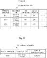
- the diagnosis data 292 will be described with reference to Fig. 8 .
- the diagnosis data 292 includes the appliance identifier, a diagnosis time, a diagnosis result, and the amount of operation data.
- the diagnosis time is a time when the state of degradation of the appliance 200 is diagnosed.
- the diagnosis result indicates the state of degradation of the appliance 200.
- KB refers to kilobyte
- min refers to minute
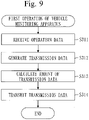
- a first operation of the vehicle monitoring apparatus 300 will be described with reference to Fig. 9 .
- step S311 the operation data reception unit 311 receives the operation data and the diagnosis data 292 transmitted from each appliance 200.
- step S312 the aggregation unit 312 aggregates the operation data of the appliances 200, and generates transmission data 391.
- the transmission data 391 is data to be transmitted to the data processing apparatus 500.
- the aggregation unit 312 creates a table including the operation data of each appliance 200.
- the created table is the transmission data 391.
- the transmission data 391 will be described with reference to Fig. 10 .
- the transmission data 391 is a data in a table format, and includes a record for each appliance 200.
- Each record includes the appliance identifier, the measurement time, and the set temperature. Each record further includes measurement values such as the exhaust temperature.
- step S313 the load monitoring unit 313 calculates the amount of transmission data by totaling the amount of operation data of the appliances 200, and .
- the amount of transmission data is the amount of the transmission data 391.
- the load monitoring unit 313 acquires the amount of operation data from the diagnosis data 292 for each appliance 200. Then, the load monitoring unit 313 calculates a total of the acquired amounts of operation data. The calculated value is the amount of transmission data.
- step S314 the transmission data transmission unit 314 transmits the transmission data 391 to the data processing apparatus 500.
- the transmission data transmission unit 314 transmits the amount of transmission data to the data processing apparatus 500.
- the transmission data transmission unit 314 transmits the load monitoring data 392 to the data processing apparatus 500.
- the load monitoring data 392 indicates the amount of transmission data.
- the load monitoring data 392 will be described with reference to Fig. 11 .
- the load monitoring data 392 includes a vehicle identifier, a calculation time, and the amount of transmission data.
- the vehicle identifier is an identifier for identifying the vehicle monitoring apparatus 300.
- the calculation time is a time when the amount of transmission data is calculated.
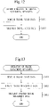
- a second operation of the vehicle monitoring apparatus 300 will be described with reference to Fig. 12 .
- step S321 the travel state acquisition unit 321 acquires travel state data.
- the travel state data is data indicating a vehicle identifier and a travel state.
- the vehicle identifier is an identifier for identifying the vehicle 110.
- the travel state is information indicating an arrival station and an arrival time.
- the arrival station is a station of arrival of the vehicle 110.
- the arrival time is a time of arrival of the vehicle 110 at the station.
- the operation state indicates that the vehicle 110 arrived at S station at 09:12:30.
- the vehicle 110 includes a travel monitoring apparatus for monitoring the travel state. Then, the travel state acquisition unit 321 acquires the travel state data from the travel monitoring apparatus.
- step S322 the travel state transmission unit 322 transmits the travel state data to the travel management apparatus 400.
- step S401 the travel state reception unit 411 receives the travel state data transmitted from the vehicle monitoring apparatus 300.
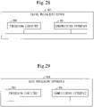
- step S402 the travel management unit 412 updates travel management data 491 on the basis of the travel state data.
- the travel management data 491 is data for managing the travel schedule of the vehicle 110 and the travel state of the vehicle 110.
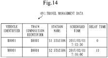
- the travel management data 491 will be described with reference to Fig. 14 .
- the travel management data 491 is stored in the storage device of the travel management apparatus 400 separately for each vehicle 110.
- the travel management data 491 for each vehicle 110 is stored in a database structured by the storage device of the travel management apparatus 400.
- the travel management data 491 in Fig. 14 is the travel management data 491 for a vehicle (R0001).
- the vehicle (R0001) is the vehicle 110 identified by a vehicle identifier "R0001".
- the travel management data 491 is data in a table format, and includes a record for each stop station.
- the stop station is a station where the vehicle 110 stops.
- Each record includes the vehicle identifier, a train composition identifier, a station name, a scheduled time, and a delay time.
- the vehicle identifier is an identifier for identifying the vehicle 110.
- the train composition identifier is an identifier for identifying a train composition.
- the station name is a name of a stop station.
- the scheduled time is a time when the vehicle 110 is scheduled to arrive at a station.
- the delay time is a time of delay from the scheduled time upon arrival of the vehicle 110 at the station.
- step S402 will be further described.
- the travel management unit 412 updates the travel management data 491 in the following manner.
- the travel management unit 412 acquires a vehicle identifier from the travel state data, and selects the travel management data 491 corresponding to the acquired vehicle identifier.
- the travel management unit 412 acquires the station name of the arrival station from the travel state data.
- the travel management unit 412 selects, in the selected travel management data 491, a record including a vehicle identifier and a station name matching the acquired vehicle identifier and the acquired station name, respectively.
- the travel management unit 412 acquires the scheduled time from the selected record.
- the travel management unit 412 acquires the arrival time from the travel state data, and calculates a time from the scheduled time to the arrival time.
- the calculated time is the delay time.
- the travel management unit 412 sets the delay time in the selected record. For example, the travel management unit 412 sets the delay time in the selected record by issuing an UPDATE command to the database where the selected travel management data 491 is stored.
- step S403 the travel management data transmission unit 413 transmits the updated travel management data 491 to the data processing apparatus 500.
- the updated travel management data 491 is the travel management data 491 updated in step S402.
- step S501 the transmission data reception unit 511 receives the transmission data 391 and the load monitoring data 392 transmitted from the vehicle monitoring apparatus 300.
- step S502 the vehicle management unit 522 updates vehicle management data 591 on the basis of the load monitoring data 392.
- the vehicle management data 591 is data for managing each vehicle 110.
- the vehicle management data 591 will be described with reference to Fig. 16 .
- the vehicle management data 591 is data in a table format, and includes a record for each vehicle 110.
- Each record includes the vehicle identifier, the train composition identifier, the amount of transmission data, a start time, and an end time.
- the start time is a time when traveling of the vehicle 110 is started.
- the end time is a time when traveling of the vehicle 110 is ended.
- step S502 will be further described.
- the vehicle management unit 522 updates the vehicle management data 591 in the following manner.
- the vehicle management unit 522 acquires the vehicle identifier and the amount of transmission data from the load monitoring data 392.
- the vehicle management unit 522 selects, in the vehicle management data 591, a record including a vehicle identifier matching the acquired vehicle identifier.
- the vehicle management unit 522 updates the amount of transmission data set in the selected record to the amount of transmission data acquired from the load monitoring data 392.
- step S503 the travel management data reception unit 521 receives the updated travel management data 491 transmitted from the travel management apparatus 400.
- step S504 the vehicle management unit 522 updates the vehicle management data 591 on the basis of the updated travel management data 491.
- the vehicle management unit 522 updates the vehicle management data 591 in the following manner.
- the updated travel management data 491 that is currently received will be referred to as current travel management data 491
- the update travel management data 491 that is previously received will be referred to as previous travel management data 491.
- the vehicle management unit 522 acquires the vehicle identifier from the current travel management data 491.
- the vehicle management unit 522 selects, in the vehicle management data 591, a record including a vehicle identifier matching the acquired vehicle identifier.
- the vehicle management unit 522 acquires the delay time from each of the current travel management data 491 and the previous travel management data 491.
- the delay time acquired from the current travel management data 491 will be referred to as a current delay time
- the delay time acquired from the previous travel management data 491 will be referred to as a previous delay time.
- the vehicle management unit 522 subtracts the previous delay time from the current delay time.
- a time that is calculated in this manner will be referred to as an adjustment time.
- the vehicle management unit 522 adds the adjustment time to the end time that is set in the selected record.
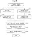
- step S510 the resource amount calculation unit 512 calculates the amount of used resources on the basis of the amount of transmission data.
- the amount of used resources is the amount of resources, in the amount of resources of computer resources, used in processing the transmission data 391. That is, the amount of used resources is the amount of resources necessary to process the transmission data 391. The amount of used resources also indicates performance necessary to process the transmission data 391.
- the computer resources are resources of the data processing apparatus 500.
- the computer resources are the processor 501, the memory 502, the auxiliary storage device 503, or a virtual machine.
- the resource amount calculation unit 512 calculates the amount of used resources in the following manner.
- the resource amount calculation unit 512 acquires the amount of transmission data from the record that is updated in step S502, among the records included in the vehicle management data 591.
- the resource amount calculation unit 512 divides the amount of transmission data by a reference amount of data.
- the value that is calculated in this manner is the amount of used resources.
- the reference amount of data is determined in advance.
- the amount of used resources is 6 instances.
- An instance is a unit indicating the amount of resources.
- Fig. 17 illustrates a specific example of the amount of used resources.
- the reference data is 1 megabyte per minute.
- the amount of transmission data is 6 megabytes per minute
- the amount of used resources is 6 instances.
- the amount of transmission data is 16 megabytes per minute
- the amount of used resources is 16 instances.
- the amount of transmission data is 11 megabytes per minute
- the amount of used resources is 11 instances.
- the amount of transmission data is 1 megabyte per minute
- the amount of used resources is 1 instance.
- step S520 the resource amount adjustment unit 513 increases or decreases the amount of secured resources to the amount of used resources.
- the amount of secured resources is the amount of resources that is secured in the amount of resources of the computer resources.
- the resource amount adjustment unit 513 operates in the following manner.
- the resource amount adjustment unit 513 decreases the amount of secured resources to the amount of used resources.
- the resource amount adjustment unit 513 increases the amount of secured resources to the amount of used resources.
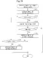
- a resource amount adjustment process (S520) will be described with reference to Fig. 18 .
- the resource amount adjustment process (S520) is performed on a regular basis. For example, the resource amount adjustment process (S520) is performed at a 10-minute interval.
- step S521 the resource amount adjustment unit 513 acquires the vehicle identifier from the record that is updated in step S502, among the records included in the vehicle management data 591.
- the resource amount adjustment unit 513 acquires the amount of secured resources corresponding to the vehicle identifier.
- the amount of secured resources corresponding to the vehicle identifier is the amount of resources secured for the transmission data 391 of the vehicle 110 identified by the vehicle identifier.
- the resource amount adjustment unit 513 inquires the OS of the amount of secured resources by issuing a command to the OS.
- the resource amount adjustment unit 513 may alternatively inquire a process, corresponding to the vehicle identifier, of the amount of secured resources by issuing a command to the process.
- the process corresponding to the vehicle identifier is a process for processing the transmission data 391 of the vehicle 110 identified by the vehicle identifier.
- step S522 the resource amount adjustment unit 513 determines whether the amount of secured resources is excessive.
- the resource amount adjustment unit 513 compares the amount of secured resources acquired in step S521 with the amount of used resources calculated in step S510. In the case where the amount of secured resources is greater than the amount of used resources, the amount of secured resources is excessive.
- step S526 In the case where the amount of secured resources is not excessive, the process proceeds to step S526.
- step S523 the resource amount adjustment unit 513 acquires a processing state corresponding to the vehicle identifier acquired in step S521.
- the processing state corresponding to the vehicle identifier is a state of processing corresponding to the vehicle identifier.
- Processing corresponding to the vehicle identifier is processing on the transmission data 391 of the vehicle 110 that is identified by the vehicle identifier.
- the resource amount adjustment unit 513 inquires the OS of the processing state by issuing a command to the OS.
- the resource amount adjustment unit 513 may alternatively inquire a process, corresponding to the vehicle identifier, of the processing state by issuing a command to the process.
- the processing state indicates complete or incomplete.
- Complete indicated by the processing state means that the processing is complete.
- Incomplete indicated by the processing state means that the processing is not complete.
- step S524 the resource amount adjustment unit 513 determines whether the processing state indicates complete.
- step S525 the resource amount adjustment unit 513 decreases the amount of secured resources corresponding to the vehicle identifier acquired in step S521 to the amount of used resources.
- the resource amount adjustment unit 513 decreases the amount of secured resources by issuing a command to the OS.
- the resource amount adjustment unit 513 may alternatively decrease the amount of secured resources by issuing a command to the process corresponding to the vehicle identifier.
- step S526 the resource amount adjustment unit 513 determines whether the amount of secured resources is insufficient.
- the resource amount adjustment unit 513 compares the amount of secured resources acquired in step S521 with the amount of used resources calculated in step S510. In the case where the amount of secured resources is smaller than the amount of used resources, the amount of secured resources is insufficient.
- step S527 In the case where the amount of secured resources is insufficient, the process proceeds to step S527.
- step S527 the resource amount adjustment unit 513 increases the amount of secured resources corresponding to the vehicle identifier acquired in step S521 to the amount of used resources.
- the resource amount adjustment unit 513 increases the amount of secured resources by issuing a command to the OS.
- the resource amount adjustment unit 513 may alternatively increase the amount of secured resources by issuing a command to the process corresponding to the vehicle identifier.
- step S527 The process is ended after step S527.
- step S530 will be described.
- step S530 the data processing unit 514 processes the transmission data 391 by using the amount of secured resources in the amount of resources of the computer resources.
- the data processing unit 514 performs specific data processing on the transmission data 391 received in step S501.
- the data processing unit 514 uses the amount of secured resources secured in step S520.
- data processing may be performed by securing just the necessary amount of resources. Accordingly, an excessive amount of resources may be prevented from being secured.
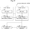
- a mode of transmission of the transmission data 391 to the travel management apparatus 400 from a first vehicle and through a second vehicle will be described with reference to Figs. 19 to 25 , focusing mainly on differences to the first embodiment.
- a configuration of the data processing system 100 will be described with reference to Fig. 19 .
- the data processing system 100 includes two vehicles (111, 112) that are connected to each other.
- the first vehicle 111 and the second vehicle 112 each correspond to the vehicle 110 according to the first embodiment.
- the first vehicle 111 includes a first vehicle monitoring apparatus 300A
- the second vehicle 112 includes a second vehicle monitoring apparatus 300B.
- the first vehicle monitoring apparatus 300A and the second vehicle monitoring apparatus 300B each correspond to the vehicle monitoring apparatus 300 according to the first embodiment.
- a configuration of the first vehicle monitoring apparatus 300A will be described with reference to Fig. 20 .
- the configuration of the first vehicle monitoring apparatus 300A is the same as the configuration of the vehicle monitoring apparatus 300 according to the first embodiment.
- a configuration of the second vehicle monitoring apparatus 300B will be described with reference to Fig. 21 .
- the second vehicle monitoring apparatus 300B includes a relay unit 315, in addition to the structural elements of the vehicle monitoring apparatus 300 according to the first embodiment.
- a data processing method is basically the same as the method according to the first embodiment.
- communication paths of the transmission data 391, the load monitoring data 392, and the travel state data are different from the communication paths according to the first embodiment.
- the first vehicle monitoring apparatus 300A transmits the transmission data 391 and the load monitoring data 392 to the data processing apparatus through the second vehicle monitoring apparatus 300B. Furthermore, the first vehicle monitoring apparatus 300A transmits the travel state data to the travel management apparatus 400 through the second vehicle monitoring apparatus 300B.
- a first operation of the first vehicle monitoring apparatus 300A will be described with reference to Fig. 22 .
- Processes from step S311A to step S313A are the same as the processes from step S311 to step S313 according to the first embodiment (see Fig. 9 ).
- step S314A the transmission data transmission unit 314 of the first vehicle monitoring apparatus 300A transmits the transmission data 391 of the first vehicle 111 and the load monitoring data 392 of the first vehicle 111 to the second vehicle monitoring apparatus 300B.
- a first operation of the second vehicle monitoring apparatus 300B will be described with reference to Fig. 23 .
- Processes from step S311B to step S314B are the same as the processes from step S311 to step S314 according to the first embodiment (see Fig. 9 ).
- the transmission data transmission unit 314 of the second vehicle monitoring apparatus 300B transmits the transmission data 391 of the second vehicle 112 and the load monitoring data 392 of the second vehicle 112 to the data processing apparatus 500.
- step S315B the relay unit 315 of the second vehicle monitoring apparatus 300B relays the transmission data 391 of the first vehicle 111 and the load monitoring data 392 of the first vehicle 111 to the data processing apparatus 500.
- the relay unit 315 receives the transmission data 391 of the first vehicle 111 and the load monitoring data 392 of the first vehicle 111. Then, the relay unit 315 transmits the transmission data 391 of the first vehicle 111 and the load monitoring data 392 of the first vehicle 111 to the data processing apparatus 500.
- a second operation of the first vehicle monitoring apparatus 300A will be described with reference to Fig. 24 .
- Step S321A is the same as step S321 according to the first embodiment (see Fig. 12 ).
- step S322A the travel state transmission unit 322 of the first vehicle monitoring apparatus 300A transmits the travel state data of the first vehicle 111 to the second vehicle monitoring apparatus 300B.
- a second operation of the second vehicle monitoring apparatus 300B will be described with reference to Fig. 25 .
- Step S321B and step S322B are the same as step S321 and step S322 according to the first embodiment (see Fig. 12 ).
- the travel state transmission unit 322 of the second vehicle monitoring apparatus 300B transmits the travel state data of the second vehicle 112 to the data processing apparatus 500.
- step S323B the relay unit 315 of the second vehicle monitoring apparatus 300B relays the travel state data of the first vehicle 111 to the data processing apparatus 500.
- the relay unit 315 receives the travel state data of the first vehicle 111. Then, the relay unit 315 transmits the travel state data of the first vehicle 111 to the data processing apparatus 500.
- the travel management apparatus 400 receives the travel state data from one vehicle, and the data processing apparatus 500 receives the transmission data 391 and the load monitoring data 392 from one vehicle. This may reduce overhead in communication.
- FIG. 26 A hardware configuration of the appliance 200 will be described with reference to Fig. 26 .
- the appliance 200 includes a processing circuitry 992.
- the processing circuitry 992 is hardware that implements the diagnosis unit 212 and the operation data amount determination unit 213.
- the processing circuitry 992 may be dedicated hardware, or may be the processor 201 that executes programs stored in the memory 202.
- the processing circuitry 992 is dedicated hardware, the processing circuitry 992 is a single circuit, multiple circuits, a programmed processor, multiple programmed processors, an ASIC, an FPGA, or a combination thereof.
- ASIC is an abbreviation for Application Specific Integrated Circuit
- FPGA is an abbreviation for Field Programmable Gate Array.
- the appliance 200 may include a plurality of processing circuits instead of the processing circuitry 992.
- the plurality of processing circuits share a role of the processing circuitry 992.
- Functions of the appliance 200 may be implemented partly by dedicated hardware, and others by software or firmware.
- processing circuitry 992 may be implemented by hardware, software, firmware, or a combination thereof.
- a hardware configuration of the vehicle monitoring apparatus 300 will be described with reference to Fig. 27 .
- the vehicle monitoring apparatus 300 includes a processing circuitry 993.
- the processing circuitry 993 is hardware that implements the aggregation unit 312, the load monitoring unit 313, and the travel state acquisition unit 321.
- the processing circuitry 993 may be dedicated hardware, or may be the processor 301 that executes programs stored in the memory 302.
- the processing circuitry 993 is dedicated hardware, the processing circuitry 993 is a single circuit, multiple circuits, a programmed processor, multiple programmed processors, an ASIC, an FPGA, or a combination thereof.
- the vehicle monitoring apparatus 300 may include a plurality of processing circuits instead of the processing circuitry 993.
- the plurality of processing circuits share a role of the processing circuitry 993.
- Functions of the vehicle monitoring apparatus 300 may be implemented partly by dedicated hardware, and others by software or firmware.
- processing circuitry 993 may be implemented by hardware, software, firmware, or a combination thereof.
- the travel management apparatus 400 includes a processing circuitry 994.
- the processing circuitry 994 is hardware that implements the travel management unit 412.
- the processing circuitry 994 may be dedicated hardware, or may be the processor 401 that executes programs stored in the memory 402.
- the processing circuitry 994 is dedicated hardware, the processing circuitry 994 is a single circuit, multiple circuits, a programmed processor, multiple programmed processors, an ASIC, an FPGA, or a combination thereof.
- the travel management apparatus 400 may include a plurality of processing circuits instead of the processing circuitry 994.
- the plurality of processing circuits share a role of the processing circuitry 994.
- Functions of the travel management apparatus 400 may be implemented partly by dedicated hardware, and others by software or firmware.
- processing circuitry 994 may be implemented by hardware, software, firmware, or a combination thereof.
- the data processing apparatus 500 includes a processing circuitry 995.
- the processing circuitry 995 is hardware that implements the resource amount calculation unit 512, the resource amount adjustment unit 513, the data processing unit 514, and the vehicle management unit 522.
- the processing circuitry 995 may be dedicated hardware, or may be the processor 501 that executes programs stored in the memory 502.
- the processing circuitry 995 is dedicated hardware, the processing circuitry 995 is a single circuit, multiple circuits, a programmed processor, multiple programmed processors, an ASIC, an FPGA, or a combination thereof.
- the data processing apparatus 500 may include a plurality of processing circuits instead of the processing circuitry 995.
- the plurality of processing circuits share a role of the processing circuitry 995.
- Functions of the data processing apparatus 500 may be implemented partly by dedicated hardware, and others by software or firmware.
- processing circuitry 995 may be implemented by hardware, software, firmware, or a combination thereof.
Landscapes
- Engineering & Computer Science (AREA)
- Computer Networks & Wireless Communication (AREA)
- Physics & Mathematics (AREA)
- Signal Processing (AREA)
- Software Systems (AREA)
- General Physics & Mathematics (AREA)
- Theoretical Computer Science (AREA)
- Thermal Sciences (AREA)
- Mechanical Engineering (AREA)
- General Engineering & Computer Science (AREA)
- Remote Sensing (AREA)
- General Health & Medical Sciences (AREA)
- Medical Informatics (AREA)
- Radar, Positioning & Navigation (AREA)
- Computing Systems (AREA)
- Health & Medical Sciences (AREA)
- Environmental & Geological Engineering (AREA)
- Data Mining & Analysis (AREA)
- Debugging And Monitoring (AREA)
- Electric Propulsion And Braking For Vehicles (AREA)
- Traffic Control Systems (AREA)
- Management, Administration, Business Operations System, And Electronic Commerce (AREA)
Claims (4)
- Datenverarbeitungssystem (100), umfassend ein oder mehrere Geräte (200), die eingerichtet sind, an einem Fahrzeug angebracht zu werden, eine Fahrzeugüberwachungsvorrichtung (300), die eingerichtet ist, an dem Fahrzeug angebracht zu werden, und eine Datenverarbeitungsvorrichtung (500), wobei die Fahrzeugüberwachungsvorrichtung (300) ein Computer ist und die Datenverarbeitungsvorrichtung (500) ein weiterer Computer ist,wobei jedes Gerät (200) aufweist:eine Messdatenerwerbungseinheit (211), die eingerichtet ist, Messdaten (291) in jeder Zeiteinheit zu erwerben,eine Diagnoseeinheit (212), die eingerichtet ist, einen Gerätezustand auf Grundlage der Messdaten (291) zu diagnostizieren, wobei die Diagnoseeinheit (212) eingerichtet ist, einen Verschlechterungszustand des Geräts (200) auf Grundlage der Messdaten (291) des Geräts zu bestimmen, undeine Betriebsdatenmenge-Bestimmungseinheit (213), die eingerichtet ist, eine Menge an Betriebsdaten auf Grundlage des Zustands des Geräts (200) zu bestimmen, wobei der Gerätezustand ein Zustand von Verschlechterung des Geräts (200) ist, und die Betriebsdatenmenge umso größer ist, je verschlechterter das Gerät (200) ist, undeine Betriebsdatenübertragungseinheit (214), die eingerichtet ist, als die Betriebsdaten, Messdaten (291), in den erworbenen Messdaten, einer Datenmenge, die der Menge an Betriebsdaten entspricht, zu übertragen und die Menge an Betriebsdaten zu übertragen,wobei die Fahrzeugüberwachungsvorrichtung (300) umfasst:eine Betriebsdatenempfangseinheit (311), die eingerichtet ist, die Betriebsdaten und die Menge an Betriebsdaten von jedem von dem einen oder den mehreren Gerät/en (200) zu empfangen;eine Aggregationseinheit (312), die eingerichtet ist, Übertragungsdaten durch Aggregieren der Betriebsdaten der Geräte zu generieren;eine Lastüberwachungseinheit (313), die eingerichtet ist, eine Menge an Übertragungsdaten durch Aufsummieren der Mengen an Betriebsdaten der Geräte zu berechnen; undeine Übertragungsdatenübertragungseinheit (314), die eingerichtet ist, die Übertragungsdaten und die Menge an Übertragungsdaten an die Datenverarbeitungsvorrichtung (500) zu übertragen;wobei die Datenverwaltungsvorrichtung (500) umfasst:eine Übertragungsdatenempfangseinheit (511), die eingerichtet ist, die Übertragungsdaten und die Menge an Übertragungsdaten von der Übertragungsdatenübertragungseinheit (314) zu empfangen;eine Ressourcenmengenberechnungseinheit (512), die eingerichtet ist, auf Grundlage der Menge an Übertragungsdaten eine Menge an genutzten Ressourcen, die eine Menge an Ressourcen ist, die bei der Verarbeitung der Übertragungsdaten genutzt wird, in einer Menge an Ressourcen von Computerressourcen zu berechnen, wobei die Ressourcenmengenberechnungseinheit (512) eingerichtet ist, die Menge an Übertragungsdaten durch eine Referenzdatenmenge zu teilen, um die Menge an genutzten Ressourcen zu berechnen, und wobei die Referenzdatenmenge im Voraus bestimmt wird;eine Ressourcenmengenanpassungseinheit (513), die eingerichtet ist, eine Menge an gesicherten Ressourcen, die eine Ressourcenmenge ist, die in der Ressourcenmenge der Computerressourcen gesichert ist, bezüglich der Menge an genutzten Ressourcen zu erhöhen oder herabzusetzen;eine Datenverarbeitungseinheit (514), die eingerichtet ist, die Übertragungsdaten unter Verwendung der Menge an gesicherten Ressourcen in der Menge an Ressourcen der Computerressourcen zu verarbeiten.
- Datenverarbeitungssystem (100) nach Anspruch 1, wobei in einem Fall, in dem die Menge an gesicherten Ressourcen größer ist als die Menge an genutzten Ressourcen, und Verarbeitung der bisherigen Übertragungsdaten bereits abgeschlossen ist, die Ressourcenmengenanpassungseinheit (513) die Menge an gesicherten Ressourcen bezüglich der Menge an genutzten Ressourcen herabsetzt.
- Datenverarbeitungssystem (100) nach Anspruch 1 oder 2, umfassend eine Bewegungsverwaltungsvorrichtung (400);wobei die Fahrzeugüberwachungsvorrichtung (300) umfasst:eine Bewegungszustandserwerbungseinheit (321), die eingerichtet ist, Bewegungszustandsdaten, anzeigend einen Betriebszustand eines Fahrzeugs (110), in dem das eine oder die mehreren Gerät/e (200) angebracht ist/sind, zu erwerben;eine Bewegungszustandsübertragungseinheit (322), die eingerichtet ist, die Bewegungszustandsdaten zu übertragen;wobei die Bewegungsverwaltungsvorrichtung (400) umfasst:eine Bewegungszustandsübertragungseinheit (411), die eingerichtet ist, die Bewegungszustandsdaten zu empfangen; undeine Bewegungsverwaltungseinheit (412), die eingerichtet ist, Bewegungsverwaltungsdaten (491) auf Grundlage der Bewegungszustandsdaten zu aktualisieren.
- Datenverarbeitungssystem (100) nach Anspruch 3, wobei die Bewegungsverwaltungsvorrichtung (400) umfasst:
eine Bewegungsverwaltungsdatenübertragungseinheit (413), die eingerichtet ist, aktualisierte Bewegungsverwaltungsdaten (491) zu übertragen;
wobei die Datenverarbeitungsvorrichtung (500) ferner umfasst:eine Bewegungsverwaltungsdatenempfangseinheit (521), die eingerichtet ist, die aktualisierten Bewegungsverwaltungsdaten zu empfangen; undeine Fahrzeugverwaltungseinheit (522), um Fahrzeugverwaltungsdaten (591) auf Grundlage der aktualisierten Bewegungsverwaltungsdaten (491) zu aktualisieren.
Applications Claiming Priority (1)
| Application Number | Priority Date | Filing Date | Title |
|---|---|---|---|
| PCT/JP2017/019371 WO2018216139A1 (ja) | 2017-05-24 | 2017-05-24 | データ処理システム、データ処理装置およびデータ処理プログラム |
Publications (3)
| Publication Number | Publication Date |
|---|---|
| EP3617878A1 EP3617878A1 (de) | 2020-03-04 |
| EP3617878A4 EP3617878A4 (de) | 2020-11-25 |
| EP3617878B1 true EP3617878B1 (de) | 2022-12-28 |
Family
ID=64396393
Family Applications (1)
| Application Number | Title | Priority Date | Filing Date |
|---|---|---|---|
| EP17911177.8A Active EP3617878B1 (de) | 2017-05-24 | 2017-05-24 | Datenverarbeitungssystem, datenverarbeitungsvorrichtung und datenverarbeitungsprogramm |
Country Status (4)
| Country | Link |
|---|---|
| US (1) | US11124046B2 (de) |
| EP (1) | EP3617878B1 (de) |
| JP (1) | JP6576601B2 (de) |
| WO (1) | WO2018216139A1 (de) |
Families Citing this family (1)
| Publication number | Priority date | Publication date | Assignee | Title |
|---|---|---|---|---|
| CN110244691B (zh) * | 2019-06-19 | 2021-04-09 | 深圳市道通科技股份有限公司 | 一种汽车诊断方法、装置及系统 |
Family Cites Families (28)
| Publication number | Priority date | Publication date | Assignee | Title |
|---|---|---|---|---|
| JP2001331332A (ja) * | 2000-05-22 | 2001-11-30 | Nippon Telegr & Teleph Corp <Ntt> | アプリケーションシステムのリソース予約方法、予約装置、リソース量推定装置およびコンピュータシステム |
| US7353269B2 (en) | 2000-12-21 | 2008-04-01 | Fujitsu Limited | Network monitoring system |
| JP3818901B2 (ja) | 2000-12-21 | 2006-09-06 | 富士通株式会社 | 記録媒体、ネットワーク監視装置、および、プログラム |
| JP4644377B2 (ja) | 2001-03-09 | 2011-03-02 | 株式会社大和証券グループ本社 | 負荷監視システム |
| JP3879471B2 (ja) | 2001-10-10 | 2007-02-14 | 株式会社日立製作所 | 計算機資源割当方法 |
| US20040267897A1 (en) * | 2003-06-24 | 2004-12-30 | Sychron Inc. | Distributed System Providing Scalable Methodology for Real-Time Control of Server Pools and Data Centers |
| EP2290979B1 (de) | 2008-06-23 | 2018-07-25 | Mitsubishi Electric Corporation | Bordüberwachungssystem für eisenbahnzüge |
| US8706863B2 (en) * | 2008-07-18 | 2014-04-22 | Apple Inc. | Systems and methods for monitoring data and bandwidth usage |
| JP4967014B2 (ja) * | 2009-12-16 | 2012-07-04 | 株式会社日立製作所 | ストリームデータ処理装置及び方法 |
| JP5939740B2 (ja) * | 2011-04-11 | 2016-06-22 | インターナショナル・ビジネス・マシーンズ・コーポレーションInternational Business Machines Corporation | 動的にリソースを割り当てる方法、システム及びプログラム |
| US8997107B2 (en) | 2011-06-28 | 2015-03-31 | Microsoft Technology Licensing, Llc | Elastic scaling for cloud-hosted batch applications |
| JP5822125B2 (ja) * | 2011-11-09 | 2015-11-24 | 日本電気株式会社 | サービス連携装置、サービス連携方法およびサービス連携プログラム |
| US9590879B2 (en) * | 2012-03-21 | 2017-03-07 | Tier 3, Inc. | Cloud application scaling framework |
| JP5982683B2 (ja) | 2013-01-17 | 2016-08-31 | 株式会社日立ソリューションズ | 計算機システム |
| US9661441B2 (en) * | 2013-04-17 | 2017-05-23 | Telefonaktiebolaget Lm Ericsson (Publ) | System and method to reduce radio resource management (RRM) related signaling in machine-to-machine (M2M) communications |
| JP6186862B2 (ja) * | 2013-05-07 | 2017-08-30 | 富士通株式会社 | 情報処理装置、省電力化制御方法および省電力化制御プログラム |
| US9602423B2 (en) * | 2013-06-28 | 2017-03-21 | Pepperdata, Inc. | Systems, methods, and devices for dynamic resource monitoring and allocation in a cluster system |
| JP6273773B2 (ja) | 2013-10-30 | 2018-02-07 | 富士ゼロックス株式会社 | 情報処理装置、情報処理システムおよびプログラム |
| JP5530020B1 (ja) | 2013-11-01 | 2014-06-25 | 株式会社日立パワーソリューションズ | 異常診断システム及び異常診断方法 |
| JP6193104B2 (ja) | 2013-12-05 | 2017-09-06 | 株式会社日立製作所 | 監視データ転送システム及び監視データ転送方法 |
| JP5530045B1 (ja) | 2014-02-10 | 2014-06-25 | 株式会社日立パワーソリューションズ | ヘルスマネージメントシステム及びヘルスマネージメント方法 |
| US9722945B2 (en) * | 2014-03-31 | 2017-08-01 | Microsoft Technology Licensing, Llc | Dynamically identifying target capacity when scaling cloud resources |
| JP6293697B2 (ja) | 2015-03-27 | 2018-03-14 | 三菱電機株式会社 | 機器診断装置及び機器診断方法 |
| WO2017001630A1 (en) * | 2015-06-30 | 2017-01-05 | British Telecommunications Public Limited Company | Model management in a dynamic qos environment |
| US10499283B2 (en) | 2015-07-01 | 2019-12-03 | Red Hat, Inc. | Data reduction in a system |
| US10554751B2 (en) * | 2016-01-27 | 2020-02-04 | Oracle International Corporation | Initial resource provisioning in cloud systems |
| US10652164B2 (en) * | 2016-04-21 | 2020-05-12 | Oracle International Corporation | Instant notification of load balance and resource scheduling based on resource capacities and event recognition |
| US10120718B2 (en) * | 2016-08-24 | 2018-11-06 | Ca, Inc. | Reservation of hardware resources in a computer system based on utilization measurements during time ranges |
-
2017
- 2017-05-24 JP JP2019519878A patent/JP6576601B2/ja active Active
- 2017-05-24 US US16/603,047 patent/US11124046B2/en active Active
- 2017-05-24 WO PCT/JP2017/019371 patent/WO2018216139A1/ja not_active Ceased
- 2017-05-24 EP EP17911177.8A patent/EP3617878B1/de active Active
Non-Patent Citations (1)
| Title |
|---|
| ANONYMOUS: "Time complexity - Wikipedia, the free encyclopedia", 14 May 2012 (2012-05-14), XP055230138, Retrieved from the Internet <URL:https://en.wikipedia.org/w/index.php?title=Time_complexity&oldid=492506715> [retrieved on 20151120] * |
Also Published As
| Publication number | Publication date |
|---|---|
| JPWO2018216139A1 (ja) | 2019-11-07 |
| EP3617878A1 (de) | 2020-03-04 |
| WO2018216139A1 (ja) | 2018-11-29 |
| EP3617878A4 (de) | 2020-11-25 |
| JP6576601B2 (ja) | 2019-09-18 |
| US11124046B2 (en) | 2021-09-21 |
| US20200189354A1 (en) | 2020-06-18 |
Similar Documents
| Publication | Publication Date | Title |
|---|---|---|
| KR102488923B1 (ko) | 자동 주차 이상 데이터 수집 방법, 장치, 저장매체 및 컴퓨터 프로그램 | |
| CN112394703B (zh) | 一种车辆故障管理系统 | |
| US9489340B2 (en) | Electrical power health monitoring system | |
| JP7607594B2 (ja) | アプリケーションプロセッサに接続された計測プロセッサを特徴とするマルチプロセッサ需給計器 | |
| CN102855369A (zh) | 一种故障信息的收集方法、系统及医疗设备 | |
| CN114600089A (zh) | 确定采集频率的方法、装置、计算设备和存储介质 | |
| KR20210046399A (ko) | 피드백을 이용한 전기차 충전소의 자가진단 방법 | |
| EP3617878B1 (de) | Datenverarbeitungssystem, datenverarbeitungsvorrichtung und datenverarbeitungsprogramm | |
| CN114979203A (zh) | 一种车辆文件的处理方法、装置、设备及存储介质 | |
| CN111737082B (zh) | 容器及容器应用的监控方法、装置、设备和介质 | |
| CN112523913B (zh) | 无人机自动启动方法及系统、存储介质及电子设备 | |
| CN113096269B (zh) | 一种信息采集方法、装置、电子设备以及存储介质 | |
| CN112235056B (zh) | 一种信号质量监测评估系统 | |
| WO2019209478A1 (en) | Gap data collection for low energy devices | |
| CN113711187B (zh) | 数据处理装置、数据处理方法及储存有程序的记录介质 | |
| CN116662128B (zh) | 虚拟机监测系统及方法 | |
| CN107104508A (zh) | 一种整合交互通信功能的停送电时间自动计算系统 | |
| US20150212809A1 (en) | Method for the Usage-Controlled Updating of a Software Product | |
| JP7013934B2 (ja) | コントローラ | |
| CN114168324B (zh) | 一种用于无人机辅助边缘计算的混合优化方法及系统 | |
| JP2012181699A (ja) | 障害調査情報資料採取システム、管理サーバ、障害調査情報資料採取方法およびそのプログラム | |
| US20160014010A1 (en) | Performance Monitoring with Reduced Transmission of Information | |
| JP2022020837A (ja) | コントローラ、制御方法およびプログラム | |
| US20250371162A1 (en) | Power supply and demand control apparatus, power supply and demand control method, and program | |
| CN118472838A (zh) | 一种基于无人机对电力设备的巡检方法、系统及巡检执行终端 |
Legal Events
| Date | Code | Title | Description |
|---|---|---|---|
| STAA | Information on the status of an ep patent application or granted ep patent |
Free format text: STATUS: THE INTERNATIONAL PUBLICATION HAS BEEN MADE |
|
| PUAI | Public reference made under article 153(3) epc to a published international application that has entered the european phase |
Free format text: ORIGINAL CODE: 0009012 |
|
| STAA | Information on the status of an ep patent application or granted ep patent |
Free format text: STATUS: REQUEST FOR EXAMINATION WAS MADE |
|
| 17P | Request for examination filed |
Effective date: 20191109 |
|
| AK | Designated contracting states |
Kind code of ref document: A1 Designated state(s): AL AT BE BG CH CY CZ DE DK EE ES FI FR GB GR HR HU IE IS IT LI LT LU LV MC MK MT NL NO PL PT RO RS SE SI SK SM TR |
|
| AX | Request for extension of the european patent |
Extension state: BA ME |
|
| RIC1 | Information provided on ipc code assigned before grant |
Ipc: G06F 9/50 20060101AFI20200513BHEP |
|
| DAV | Request for validation of the european patent (deleted) | ||
| DAX | Request for extension of the european patent (deleted) | ||
| A4 | Supplementary search report drawn up and despatched |
Effective date: 20201022 |
|
| RIC1 | Information provided on ipc code assigned before grant |
Ipc: G06F 9/50 20060101AFI20201016BHEP Ipc: H05B 1/02 20060101ALI20201016BHEP Ipc: G08C 17/00 20060101ALI20201016BHEP |
|
| STAA | Information on the status of an ep patent application or granted ep patent |
Free format text: STATUS: EXAMINATION IS IN PROGRESS |
|
| 17Q | First examination report despatched |
Effective date: 20210723 |
|
| GRAP | Despatch of communication of intention to grant a patent |
Free format text: ORIGINAL CODE: EPIDOSNIGR1 |
|
| STAA | Information on the status of an ep patent application or granted ep patent |
Free format text: STATUS: GRANT OF PATENT IS INTENDED |
|
| INTG | Intention to grant announced |
Effective date: 20220711 |
|
| GRAS | Grant fee paid |
Free format text: ORIGINAL CODE: EPIDOSNIGR3 |
|
| GRAA | (expected) grant |
Free format text: ORIGINAL CODE: 0009210 |
|
| STAA | Information on the status of an ep patent application or granted ep patent |
Free format text: STATUS: THE PATENT HAS BEEN GRANTED |
|
| AK | Designated contracting states |
Kind code of ref document: B1 Designated state(s): AL AT BE BG CH CY CZ DE DK EE ES FI FR GB GR HR HU IE IS IT LI LT LU LV MC MK MT NL NO PL PT RO RS SE SI SK SM TR |
|
| REG | Reference to a national code |
Ref country code: GB Ref legal event code: FG4D |
|
| REG | Reference to a national code |
Ref country code: CH Ref legal event code: EP |
|
| REG | Reference to a national code |
Ref country code: DE Ref legal event code: R096 Ref document number: 602017065134 Country of ref document: DE |
|
| REG | Reference to a national code |
Ref country code: AT Ref legal event code: REF Ref document number: 1540922 Country of ref document: AT Kind code of ref document: T Effective date: 20230115 |
|
| REG | Reference to a national code |
Ref country code: IE Ref legal event code: FG4D |
|
| REG | Reference to a national code |
Ref country code: LT Ref legal event code: MG9D |
|
| PG25 | Lapsed in a contracting state [announced via postgrant information from national office to epo] |
Ref country code: SE Free format text: LAPSE BECAUSE OF FAILURE TO SUBMIT A TRANSLATION OF THE DESCRIPTION OR TO PAY THE FEE WITHIN THE PRESCRIBED TIME-LIMIT Effective date: 20221228 Ref country code: NO Free format text: LAPSE BECAUSE OF FAILURE TO SUBMIT A TRANSLATION OF THE DESCRIPTION OR TO PAY THE FEE WITHIN THE PRESCRIBED TIME-LIMIT Effective date: 20230328 Ref country code: LT Free format text: LAPSE BECAUSE OF FAILURE TO SUBMIT A TRANSLATION OF THE DESCRIPTION OR TO PAY THE FEE WITHIN THE PRESCRIBED TIME-LIMIT Effective date: 20221228 Ref country code: FI Free format text: LAPSE BECAUSE OF FAILURE TO SUBMIT A TRANSLATION OF THE DESCRIPTION OR TO PAY THE FEE WITHIN THE PRESCRIBED TIME-LIMIT Effective date: 20221228 |
|
| REG | Reference to a national code |
Ref country code: NL Ref legal event code: MP Effective date: 20221228 |
|
| REG | Reference to a national code |
Ref country code: AT Ref legal event code: MK05 Ref document number: 1540922 Country of ref document: AT Kind code of ref document: T Effective date: 20221228 |
|
| PG25 | Lapsed in a contracting state [announced via postgrant information from national office to epo] |
Ref country code: RS Free format text: LAPSE BECAUSE OF FAILURE TO SUBMIT A TRANSLATION OF THE DESCRIPTION OR TO PAY THE FEE WITHIN THE PRESCRIBED TIME-LIMIT Effective date: 20221228 Ref country code: LV Free format text: LAPSE BECAUSE OF FAILURE TO SUBMIT A TRANSLATION OF THE DESCRIPTION OR TO PAY THE FEE WITHIN THE PRESCRIBED TIME-LIMIT Effective date: 20221228 Ref country code: HR Free format text: LAPSE BECAUSE OF FAILURE TO SUBMIT A TRANSLATION OF THE DESCRIPTION OR TO PAY THE FEE WITHIN THE PRESCRIBED TIME-LIMIT Effective date: 20221228 Ref country code: GR Free format text: LAPSE BECAUSE OF FAILURE TO SUBMIT A TRANSLATION OF THE DESCRIPTION OR TO PAY THE FEE WITHIN THE PRESCRIBED TIME-LIMIT Effective date: 20230329 |
|
| PG25 | Lapsed in a contracting state [announced via postgrant information from national office to epo] |
Ref country code: NL Free format text: LAPSE BECAUSE OF FAILURE TO SUBMIT A TRANSLATION OF THE DESCRIPTION OR TO PAY THE FEE WITHIN THE PRESCRIBED TIME-LIMIT Effective date: 20221228 |
|
| PG25 | Lapsed in a contracting state [announced via postgrant information from national office to epo] |
Ref country code: SM Free format text: LAPSE BECAUSE OF FAILURE TO SUBMIT A TRANSLATION OF THE DESCRIPTION OR TO PAY THE FEE WITHIN THE PRESCRIBED TIME-LIMIT Effective date: 20221228 Ref country code: RO Free format text: LAPSE BECAUSE OF FAILURE TO SUBMIT A TRANSLATION OF THE DESCRIPTION OR TO PAY THE FEE WITHIN THE PRESCRIBED TIME-LIMIT Effective date: 20221228 Ref country code: PT Free format text: LAPSE BECAUSE OF FAILURE TO SUBMIT A TRANSLATION OF THE DESCRIPTION OR TO PAY THE FEE WITHIN THE PRESCRIBED TIME-LIMIT Effective date: 20230428 Ref country code: ES Free format text: LAPSE BECAUSE OF FAILURE TO SUBMIT A TRANSLATION OF THE DESCRIPTION OR TO PAY THE FEE WITHIN THE PRESCRIBED TIME-LIMIT Effective date: 20221228 Ref country code: EE Free format text: LAPSE BECAUSE OF FAILURE TO SUBMIT A TRANSLATION OF THE DESCRIPTION OR TO PAY THE FEE WITHIN THE PRESCRIBED TIME-LIMIT Effective date: 20221228 Ref country code: CZ Free format text: LAPSE BECAUSE OF FAILURE TO SUBMIT A TRANSLATION OF THE DESCRIPTION OR TO PAY THE FEE WITHIN THE PRESCRIBED TIME-LIMIT Effective date: 20221228 Ref country code: AT Free format text: LAPSE BECAUSE OF FAILURE TO SUBMIT A TRANSLATION OF THE DESCRIPTION OR TO PAY THE FEE WITHIN THE PRESCRIBED TIME-LIMIT Effective date: 20221228 |
|
| P01 | Opt-out of the competence of the unified patent court (upc) registered |
Effective date: 20230711 |
|
| PG25 | Lapsed in a contracting state [announced via postgrant information from national office to epo] |
Ref country code: SK Free format text: LAPSE BECAUSE OF FAILURE TO SUBMIT A TRANSLATION OF THE DESCRIPTION OR TO PAY THE FEE WITHIN THE PRESCRIBED TIME-LIMIT Effective date: 20221228 Ref country code: PL Free format text: LAPSE BECAUSE OF FAILURE TO SUBMIT A TRANSLATION OF THE DESCRIPTION OR TO PAY THE FEE WITHIN THE PRESCRIBED TIME-LIMIT Effective date: 20221228 Ref country code: IS Free format text: LAPSE BECAUSE OF FAILURE TO SUBMIT A TRANSLATION OF THE DESCRIPTION OR TO PAY THE FEE WITHIN THE PRESCRIBED TIME-LIMIT Effective date: 20230428 Ref country code: AL Free format text: LAPSE BECAUSE OF FAILURE TO SUBMIT A TRANSLATION OF THE DESCRIPTION OR TO PAY THE FEE WITHIN THE PRESCRIBED TIME-LIMIT Effective date: 20221228 |
|
| REG | Reference to a national code |
Ref country code: DE Ref legal event code: R097 Ref document number: 602017065134 Country of ref document: DE |
|
| PG25 | Lapsed in a contracting state [announced via postgrant information from national office to epo] |
Ref country code: DK Free format text: LAPSE BECAUSE OF FAILURE TO SUBMIT A TRANSLATION OF THE DESCRIPTION OR TO PAY THE FEE WITHIN THE PRESCRIBED TIME-LIMIT Effective date: 20221228 |
|
| PLBE | No opposition filed within time limit |
Free format text: ORIGINAL CODE: 0009261 |
|
| STAA | Information on the status of an ep patent application or granted ep patent |
Free format text: STATUS: NO OPPOSITION FILED WITHIN TIME LIMIT |
|
| 26N | No opposition filed |
Effective date: 20230929 |
|
| REG | Reference to a national code |
Ref country code: CH Ref legal event code: PL |
|
| PG25 | Lapsed in a contracting state [announced via postgrant information from national office to epo] |
Ref country code: MC Free format text: LAPSE BECAUSE OF FAILURE TO SUBMIT A TRANSLATION OF THE DESCRIPTION OR TO PAY THE FEE WITHIN THE PRESCRIBED TIME-LIMIT Effective date: 20221228 |
|
| GBPC | Gb: european patent ceased through non-payment of renewal fee |
Effective date: 20230524 |
|
| REG | Reference to a national code |
Ref country code: BE Ref legal event code: MM Effective date: 20230531 |
|
| PG25 | Lapsed in a contracting state [announced via postgrant information from national office to epo] |
Ref country code: SI Free format text: LAPSE BECAUSE OF FAILURE TO SUBMIT A TRANSLATION OF THE DESCRIPTION OR TO PAY THE FEE WITHIN THE PRESCRIBED TIME-LIMIT Effective date: 20221228 Ref country code: MC Free format text: LAPSE BECAUSE OF FAILURE TO SUBMIT A TRANSLATION OF THE DESCRIPTION OR TO PAY THE FEE WITHIN THE PRESCRIBED TIME-LIMIT Effective date: 20221228 Ref country code: LU Free format text: LAPSE BECAUSE OF NON-PAYMENT OF DUE FEES Effective date: 20230524 Ref country code: LI Free format text: LAPSE BECAUSE OF NON-PAYMENT OF DUE FEES Effective date: 20230531 Ref country code: CH Free format text: LAPSE BECAUSE OF NON-PAYMENT OF DUE FEES Effective date: 20230531 |
|
| REG | Reference to a national code |
Ref country code: IE Ref legal event code: MM4A |
|
| PG25 | Lapsed in a contracting state [announced via postgrant information from national office to epo] |
Ref country code: IE Free format text: LAPSE BECAUSE OF NON-PAYMENT OF DUE FEES Effective date: 20230524 |
|
| PG25 | Lapsed in a contracting state [announced via postgrant information from national office to epo] |
Ref country code: IE Free format text: LAPSE BECAUSE OF NON-PAYMENT OF DUE FEES Effective date: 20230524 Ref country code: GB Free format text: LAPSE BECAUSE OF NON-PAYMENT OF DUE FEES Effective date: 20230524 |
|
| PG25 | Lapsed in a contracting state [announced via postgrant information from national office to epo] |
Ref country code: IT Free format text: LAPSE BECAUSE OF FAILURE TO SUBMIT A TRANSLATION OF THE DESCRIPTION OR TO PAY THE FEE WITHIN THE PRESCRIBED TIME-LIMIT Effective date: 20221228 Ref country code: BE Free format text: LAPSE BECAUSE OF NON-PAYMENT OF DUE FEES Effective date: 20230531 |
|
| PG25 | Lapsed in a contracting state [announced via postgrant information from national office to epo] |
Ref country code: BG Free format text: LAPSE BECAUSE OF FAILURE TO SUBMIT A TRANSLATION OF THE DESCRIPTION OR TO PAY THE FEE WITHIN THE PRESCRIBED TIME-LIMIT Effective date: 20221228 |
|
| PG25 | Lapsed in a contracting state [announced via postgrant information from national office to epo] |
Ref country code: BG Free format text: LAPSE BECAUSE OF FAILURE TO SUBMIT A TRANSLATION OF THE DESCRIPTION OR TO PAY THE FEE WITHIN THE PRESCRIBED TIME-LIMIT Effective date: 20221228 |
|
| REG | Reference to a national code |
Ref country code: DE Ref legal event code: R084 Ref document number: 602017065134 Country of ref document: DE |
|
| PGFP | Annual fee paid to national office [announced via postgrant information from national office to epo] |
Ref country code: DE Payment date: 20250402 Year of fee payment: 9 |
|
| PGFP | Annual fee paid to national office [announced via postgrant information from national office to epo] |
Ref country code: FR Payment date: 20250401 Year of fee payment: 9 |
|
| PG25 | Lapsed in a contracting state [announced via postgrant information from national office to epo] |
Ref country code: CY Free format text: LAPSE BECAUSE OF FAILURE TO SUBMIT A TRANSLATION OF THE DESCRIPTION OR TO PAY THE FEE WITHIN THE PRESCRIBED TIME-LIMIT; INVALID AB INITIO Effective date: 20170524 |
|
| PG25 | Lapsed in a contracting state [announced via postgrant information from national office to epo] |
Ref country code: HU Free format text: LAPSE BECAUSE OF FAILURE TO SUBMIT A TRANSLATION OF THE DESCRIPTION OR TO PAY THE FEE WITHIN THE PRESCRIBED TIME-LIMIT; INVALID AB INITIO Effective date: 20170524 |
|
| PG25 | Lapsed in a contracting state [announced via postgrant information from national office to epo] |
Ref country code: TR Free format text: LAPSE BECAUSE OF FAILURE TO SUBMIT A TRANSLATION OF THE DESCRIPTION OR TO PAY THE FEE WITHIN THE PRESCRIBED TIME-LIMIT Effective date: 20221228 |