EP3618427A1 - Videoüberwachungssystem - Google Patents
Videoüberwachungssystem Download PDFInfo
- Publication number
- EP3618427A1 EP3618427A1 EP17907868.8A EP17907868A EP3618427A1 EP 3618427 A1 EP3618427 A1 EP 3618427A1 EP 17907868 A EP17907868 A EP 17907868A EP 3618427 A1 EP3618427 A1 EP 3618427A1
- Authority
- EP
- European Patent Office
- Prior art keywords
- image
- person
- target person
- abandoned item
- showing
- Prior art date
- Legal status (The legal status is an assumption and is not a legal conclusion. Google has not performed a legal analysis and makes no representation as to the accuracy of the status listed.)
- Granted
Links
Images




Classifications
-
- G—PHYSICS
- G06—COMPUTING OR CALCULATING; COUNTING
- G06V—IMAGE OR VIDEO RECOGNITION OR UNDERSTANDING
- G06V20/00—Scenes; Scene-specific elements
- G06V20/50—Context or environment of the image
- G06V20/52—Surveillance or monitoring of activities, e.g. for recognising suspicious objects
-
- G—PHYSICS
- G06—COMPUTING OR CALCULATING; COUNTING
- G06T—IMAGE DATA PROCESSING OR GENERATION, IN GENERAL
- G06T7/00—Image analysis
- G06T7/20—Analysis of motion
-
- G—PHYSICS
- G06—COMPUTING OR CALCULATING; COUNTING
- G06V—IMAGE OR VIDEO RECOGNITION OR UNDERSTANDING
- G06V40/00—Recognition of biometric, human-related or animal-related patterns in image or video data
- G06V40/10—Human or animal bodies, e.g. vehicle occupants or pedestrians; Body parts, e.g. hands
- G06V40/16—Human faces, e.g. facial parts, sketches or expressions
- G06V40/172—Classification, e.g. identification
- G06V40/173—Classification, e.g. identification face re-identification, e.g. recognising unknown faces across different face tracks
-
- H—ELECTRICITY
- H04—ELECTRIC COMMUNICATION TECHNIQUE
- H04N—PICTORIAL COMMUNICATION, e.g. TELEVISION
- H04N7/00—Television systems
- H04N7/18—Closed-circuit television [CCTV] systems, i.e. systems in which the video signal is not broadcast
- H04N7/181—Closed-circuit television [CCTV] systems, i.e. systems in which the video signal is not broadcast for receiving images from a plurality of remote sources
-
- G—PHYSICS
- G06—COMPUTING OR CALCULATING; COUNTING
- G06T—IMAGE DATA PROCESSING OR GENERATION, IN GENERAL
- G06T2207/00—Indexing scheme for image analysis or image enhancement
- G06T2207/10—Image acquisition modality
- G06T2207/10016—Video; Image sequence
Definitions
- the present invention relates to an image monitoring system for monitoring images taken by imaging devices, and in particular to a system for identifying a person who has left an abandoned item and tracking the movement of the person.
- an image monitoring system has been arranged in facilities to which an unspecified large number of people visit such as airports, train station premises and shopping malls for the purpose of crime deterrence or accident prevention.
- image monitoring systems include an abandoned item detection system for detecting an abandoned item by monitoring images (Patent Literature 1, for example) and a person search system for searching an identified person within images (Patent Literature 2, for example).
- the prior art requires the user to visually confirm images and do the manual input work for a search, and therefore, it is not comfortable for the user to use the system, which is thus inconvenient, and lacks the real-time property.
- the present invention is provided in view of the above-described conventional situation, and an object thereof is to provide an image monitoring system that makes it possible to reduce the burden on the user from the work for identifying a person who has left an abandoned item and tracking the movement of the person.
- the image monitoring system or the image monitoring method according to the present invention are formed as follows.
- the present invention can provide an image monitoring system which makes it possible to reduce the burden on the user from the work of identifying a person who left an abandoned item and tracking the movement of the person.
- FIG. 1 is a diagram showing an example of the configuration of the image monitoring system according to the embodiment of the present invention.
- the image monitoring system according to the present embodiment is provided with: a plurality (N) of imaging devices 100(1) through 100(N); a monitoring server 200; and a user terminal 300, and communication between these devices is established via a network 400.
- the image monitoring system is arranged in a facility to which an unspecified number of people visit such as an airport, train station premises or a shopping mall.
- the network 400 is used for the exchange of signals or data between the respective devices.
- a LAN local area network
- a WAN wide area network
- the Internet or any other form of a network
- the respective devices in the image monitoring system can communicate with another device via the network 400 by using a wired line, a wireless line or a combination of these.
- the imaging devices 100(1) through 100(N) are devices such as IP cameras (network cameras) that are installed in the respective places within the facility where the image monitoring system is arranged.
- Each of the imaging devices 100 is provided with an imaging element such as a CCD (charge coupled device) or a CMOS (complementary metal oxide semiconductor) and carries out a digital conversion on the images that have been taken, which are transmitted to the monitoring server 200 via the network 400.
- CCD charge coupled device
- CMOS complementary metal oxide semiconductor
- the user terminal 300 is a device used by the user (surveillant) in the present system.
- the user terminal 300 has a function of transmitting input data to the monitoring server 200 upon the reception of an input resulting from the operation by the user and a function of receiving the provided data transmitted from the monitoring server 200 so as to display the provided data on a screen.
- the user terminal 300 may be an installation-type device or a portable device such as a smartphone or a tablet, and thus, various types of devices can be used.
- the monitoring server 200 is a server having a target person tracking function of identifying a person who has left an abandoned item (suspicious looking person, for example) as a target person on the basis of each video (images) taken by any of the plurality of imaging devices 100 and tracking the movement of the target person.
- the monitoring server 200 has as a process unit concerning the target person tracking function an image storage unit 201, an abandoned item detection unit 202, a person identification unit 203, a personal feature value acquisition unit 204, a person search unit 205 and a result display unit 206.
- the image storage unit 201 carries out a process for storing images that have been transmitted from each of the plurality of imaging devices 100.
- the image storage unit 201 stores images that have been received from the imaging devices 100 in a randomly accessible recording medium such as an HDD (hard disc drive), for example.
- the attribution data such as the imaging device number for identifying the imaging device 100 that took an image and the imaging time at which the image was taken is attached to each image received from the imaging device 100, and these pieces of attribute data are also stored in the recording medium.
- the abandoned item detection unit 202 carries out an abandoned item detection process for detecting an abandoned item shown in an image that had been taken by any of the plurality of imaging devices 100.
- an abandoned item is detected, for example, through the comparison between an image that has been taken and a reference image that has been prepared in advance.
- the image that has been taken and the reference image are respectively binarized, and each pixel is differentiated between the binarized images.
- a pixel region where the differential value is a predetermined threshold value or greater is sampled, and in the case where the sampled pixel region is a bundle having a predetermined size or greater, it is estimated that there is an abandoned item in this pixel region.
- a pixel region having a bundle of a predetermined size or greater as an abandoned item after carrying out an expansion/contraction process, a numbering process, a noise component removing process and the like on the sampled pixel region in order to increase the precision in the detection of an abandoned item. It is also preferable to prepare in advance a plurality of reference images having different brightness so as to select the reference image of which the brightness is the closest to the brightness of the image that has been taken before the comparison with the image that has been taken.
- the person identification unit 203 in the case where an abandoned item is detected by the abandoned item detection unit 202, carries out an abandonment timing image specification process where an image at the moment when an abandoned item is placed is specified as an image of abandonment timing, and carries out a person identification process for identifying at least one person shown in the image of abandonment timing as a target person.
- an image of abandonment timing is specified by processing a sequence of images that have been received from the imaging device 100 that took the image from which an abandoned item was detected in the time series order or in the reverse order thereof.
- an image is specified at the point in time when an abandoned item was discovered (point in time when it was estimated that there was an abandoned item) by following the log in the abandoned item detection process, and images are processed by playing the stream of the images in reverse (towards the past) starting from this point in time.
- the image at the moment when the abandoned item disappears and the original backdrop image appears, that is to say, the image directly before the abandoned item was placed is specified as the image of abandonment timing.
- the images are processed by following the stream of images in the forward direction (toward the future) starting from this point in time.
- the image at the moment where the original backdrop image disappeared and the abandoned item appeared, that is to say, the image directly after the abandoned item has been placed is specified as the image of abandonment timing.
- a person detection process is carried out on the image of abandonment timing so as to detect a person shown in the image of abandonment timing.
- the person detection process can be carried out by using an arbitrary technique, and for example, a publicly-known face recognition technology can be used.
- the person is identified as the target person.
- the distance between the place of the abandoned item and the place of each person in the image of abandonment timing is calculated, and the person whose calculated distance is the shortest is identified as the target person.
- a person whose calculated distance is a predetermined threshold value or less is identified as a target person, or several people whose calculated distance is shorter than others are identified as target people.
- the location of the abandoned item is the location that represents the image region of the abandoned item in the image of abandonment timing.
- the coordinates of the center of the image region of the abandoned item can be used.
- the location of a person is the location that represents the image region of the person in the image of abandonment timing.
- the coordinates of the center of the image region of the entirety of the person, the coordinates of the center of the image region of the head or the face, the coordinates of the center of the image region of the hand that is closer to the abandoned item, or the like can be used.
- the period of time during which a person is shown together with the abandoned item is calculated for each person who is shown together with the abandoned item from the images before the abandoned item was detected, and the person whose calculated period of time is the longest is identified as the target person.
- a person whose calculated period of time is a predetermined threshold value or greater is identified as a target person or several people whose calculated period of time is longer than other are identified as target people.
- the personal feature value acquisition unit 204 carries out a personal feature value acquisition process for acquiring a personal feature value on the basis of the image showing a person.
- a personal feature value acquisition process for acquiring a personal feature value on the basis of the image showing a person.
- the personal feature value acquisition unit 204 makes the acquired personal feature value correspond to the image from which it was acquired when storing it in the image storage unit 201.
- a plurality of personal feature values is made to correspond to an image showing a plurality of people.
- the personal feature value acquisition unit 204 acquires the personal feature value of a target person on the basis of the image of abandonment timing that had been specified by the person identification unit 203.
- the personal feature value of the target person is used as a search key to search for a person in the person search unit 205.
- the personal feature value is a value that represents the features of a person included in an image.
- the personal feature value includes at least a facial feature value that indicates the features of a face or a worn clothing value that indicates the features of the worn clothing (including a hat, a carried item, accessories and the like).
- the facial feature value can be acquired by digitizing the contour and direction of the face, the color of the skin, the size / the shape / the positional relationship and the like of the main components of the face (eyes, nose, mouth and the like).
- the worn clothing feature value can be acquired by estimating the positions of the head, the upper body, the lower body and the like of a person, and digitizing the color, the shape and the like of the clothing worn by the person (a hat, a jacket, trousers, a carried item and accessories, for example).
- the facial feature value and the worn clothing feature value can be acquired by using an arbitrary technique and by using a technique that is disclosed in Patent Literature 1, for example.
- the person search unit 205 carries out a person search process for searching for an image showing a target person from among the images that have been taken by each of the plurality of imaging devices 100 on the basis of the personal feature value of the target person that has been acquired on the basis of the image of abandonment timing specified by the person identification unit 203.
- the person search process for example, the personal feature value acquired for a target person is compared with the personal feature value acquired from another image so as to calculate the similarity. In the case where the similarity is a predetermined threshold value or greater, it is determined that the image shows the target person.
- the person search process includes a past search where a search process is carried out on the images within the image storage unit 201 by going backward from the present time and a real-time search where a search process is carried out on the images that are transmitted from the imaging devices 100 afterwards.
- the result display unit 206 carries out a tracking result display process for outputting on the screen of the user terminal 300 the display showing the movement of a target person on the basis of the search results by the person search unit 205.
- the movement of the target person can be tracked on the basis of the imaging device number and the imaging time that are made to correspond to each image of the search results.
- the order in which the imaging device numbers are aligned can be specified in the case where the respective search result images are sorted in the order of the imaging time so as to track that a target person has moved through the areas where the image was taken by an imaging device 100 in the order that corresponds to the specified order of the aligned imaging device numbers.
- An example of the display of the information that indicates the movement of a target person is described below.
- FIG. 2 shows an example of the hardware configuration of the monitoring server 200.
- the monitoring server 200 is formed of, for example, a CPU (central processing unit) 221, a main memory unit 222, an auxiliary memory unit 223 and a network interface (I/F) 224 that are linked through a bus 225.
- a CPU central processing unit
- main memory unit 222 main memory
- auxiliary memory unit 223 main memory
- I/F network interface
- the CPU 221 controls the respective units in the monitoring server 200 and runs a program for making various functions work in accordance with the present invention.
- the main memory unit 222 is implemented by a semiconductor device such as a DRAM (dynamic random access memory), which is an intermediating memory for loading and storing a program that is to be run by the CPU 221.
- the auxiliary memory unit 223 is implemented by an HDD or a flash memory, which is a memory of which the capacity is larger than that of the main memory unit 222 and which stores various types of data or programs.
- the network I/F 224 is an interface for receiving images that have been transmitted from the imaging devices 100, for receiving various types of input data that have been transmitted from the user terminal 300, for transmitting various types of supply data to the user terminal 300 and the like via the network 400.
- the monitoring server 200 in the present example is formed in such a manner that the programs that prescribe the operations of the above-described respective process units 202 through 206 are stored in the auxiliary memory unit 223 and uploaded to the main memory unit 222 in order to be run in the CPU 221, and thus, the respective process unit 201 through 206 are realized.
- part of the entirety of the process units 201 through 206 may be realized with a dedicated hardware circuit instead of being realized by the software as described above.
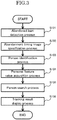
- FIG. 3 is a flow chart showing an example of a process flow for tracking a target person by means of the monitoring server 200.
- the monitoring server 200 allows the abandoned item detection unit 202 to carry out an abandoned item detection process (step S101).
- the abandoned item detection process is carried out whenever an image is received from an imaging device 100 or whenever the received image is stored in the image storage unit 201.
- the monitoring server 200 Upon the detection of an abandoned item, the monitoring server 200 issues a message to that effect to the user terminal 300 so as to let the user at the user terminal 300 know of the detection of an abandoned item.
- the monitoring server 200 allows the person identification unit 203 to carry out an abandonment timing image specification process so as to specify the image at the moment when the abandoned item was placed as an image of abandonment timing (step S102).
- the monitoring server 200 allows the person identification unit 203 to carry out a person identification process so as to identify at least one person shown in the image of abandonment timing as a target person (step S103).
- the monitoring server 200 allows the personal feature value acquisition unit 204 to carry out a personal feature value acquisition process so as to acquire a personal feature value of the target person (step S104).
- the monitoring server 200 allows the person search unit 205 to carry out a person search process on the basis of the personal feature value of the target person so as to search for images showing the target person (step S105).
- the monitoring server 200 allows the result display unit 206 to carry out a track result display process so as to display information showing the movement of the target person on the screen of the user terminal 300 (step S106).
- step S102 through step S106 may be carried out after waiting for the instruction from the user who has confirmed the message to the effect that an abandoned item has been detected or immediately after the detection of an abandoned item.
- steps S104 through S106 may be repeated for the respective target people or may be carried out on any of the target people.
- the identified plurality of target people may be shown to the user at the user terminal 300 so that the user can select a target person from among them.
- FIG. 4 shows an example of the display of the results of the tracking of a target person.
- the example of the display in FIG. 4 has a map display region 241 showing the route which the target person has moved on a map, and a timeline display region 246 showing respective images of the target person that are aligned chronologically.
- the map display region 241 shows places C1 through C4 at which an imaging device is arranged, and points T1 through T6 at which the target person is shown on a map of the area that includes the places C1 through C4 at which an imaging device that has taken an image of the target person are arranged.
- the map within the facility where the present system is arranged and the places (C1 through C4) at which an imaging device is arranged within the facility may be stored in advance.
- the place at which the imaging device that has taken an image of the target person is arranged can be specified from the imaging device numbers that are attached to the images showing the target person so as to be displayed on the map.
- timeline display region 246 displays the images that have been taken at the respective points (T1 through T6) that are aligned chronologically.
- the map in the map display region 241 shows a route 242 which the target person has moved in such a manner that the route 242 overlaps the map.
- the route 242 can be estimated on the basis of the coordinates of the respective points (T1 through T6), the time at which the target person has passed by each point (time at which the image was taken), and the general walking speed that has been preset.
- the route 242 is estimated by the result display unit 206 in the present example.
- the route 242 is estimated on the basis of the search results gained from the search in the past by the person search unit 205.
- the following route 243 of the target person may be added on the basis of the search results gained from the following real time search.
- a route which the target person will highly likely pass through afterwards may be expected on the basis of the past and present routes 242 and 243, and thus, a function of displaying a future route may be provided.
- FIG. 5 shows another example of the display of the results of the tracking of a target person.
- the example of the display in FIG. 5 has a timeline detail display region 251 showing images of a target person that are aligned chronologically for each imaging device.
- the timeline detail display region 251 is gained by dividing the timeline display region 246 in the first example of the display ( FIG. 4 ) for the respective imaging devices.
- the timeline detail display region 251 in FIG. 5 may be used instead of the timeline display region 246 in FIG. 4 .
- the image monitoring system in the present example is configured in such a manner that: the abandoned item detection unit 202 detects an abandoned item that is shown in an image taken by any of the plurality of imaging devices 100; in the case where an abandoned item is detected, the person identification unit 203 specifies the image directly before or directly after the appearance of the abandoned item as an image of abandonment timing, and identifies at least one person shown in the image of abandonment timing as a target person; the person search unit 205 searches for an image showing the target person from among the images respectively taken by any of the plurality of imaging devices 100; and the result display unit 206 outputs the display showing the movement of the target person on the screen of the user terminal 300 on the basis of the imaging device that has taken each image showing the target person and the imaging time at which each image showing the target person was taken.
- the image monitoring system in the present embodiment makes it possible to automate the processes from the detection of an abandoned item to the tracking of the movement of a target person, and therefore, the burden of the user who has to monitor within a facility can be reduced, and a target person can be efficiently tracked in real time.
- the image monitoring system in the present example is further provided with a personal feature value acquisition unit 204 for acquiring a personal feature value that includes a facial feature value and a worn clothing feature value of a target person on the basis of the image of abandonment timing, and thus is configured in such a manner that the person search unit 205 searches for an image showing a target person on the basis of the personal feature value of the target person. Therefore, the image monitoring system in the present example allows for a search by using not only the facial feature value of a target person, but also a worn clothing feature value, which makes it possible to search for other images showing the target person from the clothing or the like worn by the person even in the case where the image of abandonment timing does not clearly show the face of the target person.
- the image monitoring system in the present example is configured in such a manner that the result display unit 206 outputs on the screen the display showing a route which a target person has moved on a map or the display showing the images of the target person that are aligned chronologically for each imaging device as the display showing the movement of the target person. Accordingly, the image monitoring system in the present example makes it possible for the user at the user terminal 300 to easily confirm the target person who has left an abandoned item (including a suspicious person who has intentionally abandoned the item or a person who has unintentionally left or lost the item) and the movement of the person.
- an abandoned item including a suspicious person who has intentionally abandoned the item or a person who has unintentionally left or lost the item
- the image monitoring system in the present example is configured in such a manner that the person identification unit 203 identifies a target person on the basis of the length of the period of time a person is shown together with the abandoned item in the case where an image of abandonment timing cannot be specified. Accordingly, the image monitoring system in the present example can identify as a target person a person who highly likely left an abandoned item even in the case where an image of abandonment timing cannot be specified.
- the results of a person search may include not only images showing a target person, but also images showing other people, and in the case where the number of images of the other people is large, it is possible for the personal feature value used for the person search to be inappropriate. That is to say, it is assumed that the features that differentiate the target person from other people are not exhibited in the space of the feature value in the case where the search results include many images of other people. Therefore, several weighing patterns where the weight given to each element of the clothing feature value (hat, jacket, trousers, carried item, accessories and the like) is differentiated may be prepared so that the respective weighing patterns are applied to the trials of a person search in order to automatically select the weighing pattern that makes it easy to distinguish the resulting target person from other people.
- Each weighing pattern is applied for a trial of a person search, and the number of times that each person has been searched for in each trial is recorded.
- the probability of a person who has been searched for a large number of times being the target person is high.
- a predetermined number of people who have been searched for many times is selected in the order of the number of times of being searched. These people are referred to as the candidate people for the target person.
- the weighing pattern where the candidate people have been searched for the greatest number of times from among the search results is selected from the respective weighing patterns.
- This weighing pattern is a weighing pattern that provides a high probability of a target person being included many times, and thus provides a great weight to the feature value that contributes to the differentiation between the target person and other people while providing a small weight to the feature value that does not contribute to the differentiation.
- This weighing pattern can be used to increase the precision of a person search.
- a weighing pattern that includes a large number of candidate people can be used to exclude people who clearly seem unlikely to be a target person at the stage before the target person is identified instead of using only one weighing pattern to finally determine the target person.
- a logical multiplication process can be carried out on the search results, for example, in order to increase the probability of a target person being included, and thus, the candidates for a target person can be narrowed down through the exclusion of unlikely candidates from the search results.
- an image of the same person that clearly shows the face may be selected from among the images covering several time frames before and after the image of abandonment timing that have been taken by the same imaging device, and then, a facial feature value (and a worn clothing feature value) may be acquired from this image.
- a facial feature value and a worn clothing feature value
- whether or not the person in the images is the same can be determined from the positional relationships of the image region of the person between the images (frames), the similarity of the worn clothing feature value of the person between the images and the like.
- the configurations of the system and the devices according to the present invention may not necessarily be limited to those in the above, and various configurations may be used.
- the present invention to provide a method or a system according to which the processes according to the present invention are carried out, a program for implementing such a method or system, a recording medium for storing such a program, or the like.
- the present invention can be applied to an image monitoring system for monitoring images taken by imaging devices.
Landscapes
- Engineering & Computer Science (AREA)
- Multimedia (AREA)
- Physics & Mathematics (AREA)
- Theoretical Computer Science (AREA)
- General Physics & Mathematics (AREA)
- Signal Processing (AREA)
- Computer Vision & Pattern Recognition (AREA)
- Health & Medical Sciences (AREA)
- Human Computer Interaction (AREA)
- Oral & Maxillofacial Surgery (AREA)
- General Health & Medical Sciences (AREA)
- Closed-Circuit Television Systems (AREA)
- Image Analysis (AREA)
- Alarm Systems (AREA)
Applications Claiming Priority (1)
| Application Number | Priority Date | Filing Date | Title |
|---|---|---|---|
| PCT/JP2017/017077 WO2018198373A1 (ja) | 2017-04-28 | 2017-04-28 | 映像監視システム |
Publications (3)
| Publication Number | Publication Date |
|---|---|
| EP3618427A1 true EP3618427A1 (de) | 2020-03-04 |
| EP3618427A4 EP3618427A4 (de) | 2020-08-26 |
| EP3618427B1 EP3618427B1 (de) | 2022-04-13 |
Family
ID=63919576
Family Applications (1)
| Application Number | Title | Priority Date | Filing Date |
|---|---|---|---|
| EP17907868.8A Active EP3618427B1 (de) | 2017-04-28 | 2017-04-28 | Videoüberwachungssystem |
Country Status (5)
| Country | Link |
|---|---|
| US (1) | US11017537B2 (de) |
| EP (1) | EP3618427B1 (de) |
| JP (1) | JP6674584B2 (de) |
| SG (1) | SG11201908010YA (de) |
| WO (1) | WO2018198373A1 (de) |
Cited By (2)
| Publication number | Priority date | Publication date | Assignee | Title |
|---|---|---|---|---|
| WO2023084379A1 (en) * | 2021-11-09 | 2023-05-19 | AvaSure, LLC | Predictive system for elopement detection |
| EP4715761A1 (de) * | 2024-09-20 | 2026-03-25 | Tyco Fire & Security GmbH | Kombiniertes objektdetektions- und verhaltensdetektionssystem |
Families Citing this family (17)
| Publication number | Priority date | Publication date | Assignee | Title |
|---|---|---|---|---|
| SG11201909105TA (en) | 2017-03-30 | 2019-11-28 | Nec Corp | Information processing apparatus, control method, and program |
| CN111291585B (zh) * | 2018-12-06 | 2023-12-08 | 杭州海康威视数字技术股份有限公司 | 一种基于gps的目标跟踪系统、方法、装置及球机 |
| WO2020115910A1 (ja) | 2018-12-07 | 2020-06-11 | 日本電気株式会社 | 情報処理システム、情報処理装置、情報処理方法、およびプログラム |
| JP7298729B2 (ja) * | 2018-12-07 | 2023-06-27 | 日本電気株式会社 | 情報処理システム、情報処理装置、情報処理方法、およびプログラム |
| JP7371806B2 (ja) * | 2018-12-07 | 2023-10-31 | 日本電気株式会社 | 情報処理装置、情報処理方法、およびプログラム |
| WO2020118430A1 (en) * | 2018-12-12 | 2020-06-18 | Avigilon Corporation | Object left behind detection |
| EP3934240A4 (de) * | 2019-03-01 | 2022-10-12 | Hitachi, Ltd. | Vorrichtung zur erkennung unbeaufsichtigter objekte und verfahren zur erkennung unbeaufsichtigter objekte |
| JP7160192B2 (ja) * | 2019-05-21 | 2022-10-25 | 日本電気株式会社 | エリア管理装置、エリア管理方法及びプログラム |
| KR102712459B1 (ko) * | 2019-11-19 | 2024-10-07 | 엘지전자 주식회사 | 전자 장치 및 그의 동작 방법 |
| DE102019134813A1 (de) * | 2019-12-17 | 2021-06-17 | G2K Group GmbH | Ereignis-Überwachung in einem räumlichen Bereich |
| KR102413960B1 (ko) * | 2020-10-12 | 2022-06-27 | 서울대학교산학협력단 | 질의 응답 장치 및 방법 |
| CN112926431A (zh) * | 2021-02-20 | 2021-06-08 | 北京市商汤科技开发有限公司 | 垃圾检测方法、装置、设备及计算机存储介质 |
| CN117441189A (zh) | 2021-06-11 | 2024-01-23 | 松下知识产权经营株式会社 | 作业分析装置以及方法 |
| US11914749B2 (en) * | 2021-12-07 | 2024-02-27 | Motorola Solutions, Inc. | Selective and protected release of private information to an incident response team |
| US20240013401A1 (en) * | 2022-07-08 | 2024-01-11 | Honeywell International Inc. | Identifying and tracking abandoned objects using video analytics |
| CN116012360B (zh) * | 2023-01-18 | 2026-04-21 | 中国工商银行股份有限公司 | 遗留物品检测方法、装置、设备、介质和程序产品 |
| CN120032149B (zh) * | 2025-04-15 | 2025-07-11 | 杭州海康威视数字技术股份有限公司 | 一种基于图像检测自然语言描述目标的方法及电子设备 |
Family Cites Families (12)
| Publication number | Priority date | Publication date | Assignee | Title |
|---|---|---|---|---|
| US20060018516A1 (en) * | 2004-07-22 | 2006-01-26 | Masoud Osama T | Monitoring activity using video information |
| EP1867167A4 (de) * | 2005-04-03 | 2009-05-06 | Nice Systems Ltd | Vorrichtung und verfahren zur halbautomatischen verfolgung und untersuchung eines objekts oder eines ereignisses an einem überwachten standort |
| JP4945477B2 (ja) | 2008-02-21 | 2012-06-06 | 株式会社日立国際電気 | 監視システム、人物検索方法 |
| JP5203319B2 (ja) | 2009-08-25 | 2013-06-05 | セコム株式会社 | 置き去り監視装置 |
| JP2011061651A (ja) | 2009-09-14 | 2011-03-24 | Hitachi Kokusai Electric Inc | 不審物検知システム |
| US20130282446A1 (en) * | 2010-04-15 | 2013-10-24 | Colin Dobell | Methods and systems for capturing, measuring, sharing and influencing the behavioural qualities of a service performance |
| JP5691764B2 (ja) * | 2011-04-12 | 2015-04-01 | サクサ株式会社 | 置き去り又は持ち去り検知システム |
| JP5691807B2 (ja) | 2011-04-28 | 2015-04-01 | サクサ株式会社 | 置き去り又は持ち去り検知システム |
| US9396538B2 (en) | 2012-09-19 | 2016-07-19 | Nec Corporation | Image processing system, image processing method, and program |
| WO2014050518A1 (ja) * | 2012-09-28 | 2014-04-03 | 日本電気株式会社 | 情報処理装置、情報処理方法および情報処理プログラム |
| JP5954106B2 (ja) | 2012-10-22 | 2016-07-20 | ソニー株式会社 | 情報処理装置、情報処理方法、プログラム、及び情報処理システム |
| EP3494428A4 (de) * | 2016-08-02 | 2020-04-08 | Atlas5D, Inc. | Systeme und verfahren zur identifizierung von personen und/oder identifizierung und quantifizierung von schmerzen, müdigkeit, stimmung und absicht mit schutz der privatsphäre |
-
2017
- 2017-04-28 JP JP2019515072A patent/JP6674584B2/ja active Active
- 2017-04-28 US US16/490,043 patent/US11017537B2/en active Active
- 2017-04-28 SG SG11201908010YA patent/SG11201908010YA/en unknown
- 2017-04-28 EP EP17907868.8A patent/EP3618427B1/de active Active
- 2017-04-28 WO PCT/JP2017/017077 patent/WO2018198373A1/ja not_active Ceased
Cited By (3)
| Publication number | Priority date | Publication date | Assignee | Title |
|---|---|---|---|---|
| WO2023084379A1 (en) * | 2021-11-09 | 2023-05-19 | AvaSure, LLC | Predictive system for elopement detection |
| US12444196B2 (en) | 2021-11-09 | 2025-10-14 | AvaSure, LLC | Predictive system for elopement detection |
| EP4715761A1 (de) * | 2024-09-20 | 2026-03-25 | Tyco Fire & Security GmbH | Kombiniertes objektdetektions- und verhaltensdetektionssystem |
Also Published As
| Publication number | Publication date |
|---|---|
| EP3618427B1 (de) | 2022-04-13 |
| JPWO2018198373A1 (ja) | 2019-11-14 |
| SG11201908010YA (en) | 2019-09-27 |
| US11017537B2 (en) | 2021-05-25 |
| JP6674584B2 (ja) | 2020-04-01 |
| WO2018198373A1 (ja) | 2018-11-01 |
| US20200043174A1 (en) | 2020-02-06 |
| EP3618427A4 (de) | 2020-08-26 |
Similar Documents
| Publication | Publication Date | Title |
|---|---|---|
| US11017537B2 (en) | Image monitoring system | |
| US11157778B2 (en) | Image analysis system, image analysis method, and storage medium | |
| JP6399356B2 (ja) | 追跡支援装置、追跡支援システムおよび追跡支援方法 | |
| US12340666B2 (en) | Investigation generation in an observation and surveillance system | |
| WO2016136144A1 (ja) | モニタリング装置およびモニタリング方法 | |
| JP2022168070A (ja) | 人物検出システム | |
| JP2018160219A (ja) | 移動経路予測装置、及び移動経路予測方法 | |
| WO2018096787A1 (ja) | 人物行動監視装置および人物行動監視システム | |
| JP2018005555A (ja) | 画像処理装置、情報処理装置、および方法、並びにプログラム | |
| US11120838B2 (en) | Information processing apparatus, control method, and program | |
| WO2018179202A1 (ja) | 情報処理装置、制御方法、及びプログラム | |
| JPWO2014061342A1 (ja) | 情報処理システム、情報処理方法及びプログラム | |
| TWI794593B (zh) | 物體追蹤裝置、控制方法以及程式 | |
| JP2010244462A (ja) | 人物追跡装置、人物追跡方法及びプログラム | |
| JP6396682B2 (ja) | 監視カメラシステム | |
| EP3598764A1 (de) | Ergänzung von videomaterial | |
| US20180197000A1 (en) | Image processing device and image processing system | |
| JP2019096062A (ja) | 物体追跡装置、物体追跡方法、および、物体追跡プログラム | |
| CN111108752A (zh) | 街景服务方法及执行该方法的装置 | |
| JP2018195992A (ja) | 人物グループ追跡装置および人物グループ追跡方法 | |
| JP2015088816A (ja) | 画像監視システム | |
| WO2016194275A1 (ja) | 動線分析システム、カメラ装置及び動線分析方法 | |
| JP5909712B1 (ja) | 動線分析システム、カメラ装置及び動線分析方法 | |
| JP2008250693A (ja) | 映像検索装置 | |
| JP5051885B2 (ja) | 人物検索装置及び人物検索方法 |
Legal Events
| Date | Code | Title | Description |
|---|---|---|---|
| STAA | Information on the status of an ep patent application or granted ep patent |
Free format text: STATUS: THE INTERNATIONAL PUBLICATION HAS BEEN MADE |
|
| PUAI | Public reference made under article 153(3) epc to a published international application that has entered the european phase |
Free format text: ORIGINAL CODE: 0009012 |
|
| STAA | Information on the status of an ep patent application or granted ep patent |
Free format text: STATUS: REQUEST FOR EXAMINATION WAS MADE |
|
| 17P | Request for examination filed |
Effective date: 20190829 |
|
| AK | Designated contracting states |
Kind code of ref document: A1 Designated state(s): AL AT BE BG CH CY CZ DE DK EE ES FI FR GB GR HR HU IE IS IT LI LT LU LV MC MK MT NL NO PL PT RO RS SE SI SK SM TR |
|
| AX | Request for extension of the european patent |
Extension state: BA ME |
|
| DAV | Request for validation of the european patent (deleted) | ||
| DAX | Request for extension of the european patent (deleted) | ||
| A4 | Supplementary search report drawn up and despatched |
Effective date: 20200724 |
|
| RIC1 | Information provided on ipc code assigned before grant |
Ipc: H04N 7/18 20060101AFI20200720BHEP |
|
| STAA | Information on the status of an ep patent application or granted ep patent |
Free format text: STATUS: EXAMINATION IS IN PROGRESS |
|
| 17Q | First examination report despatched |
Effective date: 20210305 |
|
| GRAP | Despatch of communication of intention to grant a patent |
Free format text: ORIGINAL CODE: EPIDOSNIGR1 |
|
| STAA | Information on the status of an ep patent application or granted ep patent |
Free format text: STATUS: GRANT OF PATENT IS INTENDED |
|
| INTG | Intention to grant announced |
Effective date: 20220202 |
|
| GRAS | Grant fee paid |
Free format text: ORIGINAL CODE: EPIDOSNIGR3 |
|
| RAP3 | Party data changed (applicant data changed or rights of an application transferred) |
Owner name: HITACHI KOKUSAI ELECTRIC INC. |
|
| GRAA | (expected) grant |
Free format text: ORIGINAL CODE: 0009210 |
|
| STAA | Information on the status of an ep patent application or granted ep patent |
Free format text: STATUS: THE PATENT HAS BEEN GRANTED |
|
| AK | Designated contracting states |
Kind code of ref document: B1 Designated state(s): AL AT BE BG CH CY CZ DE DK EE ES FI FR GB GR HR HU IE IS IT LI LT LU LV MC MK MT NL NO PL PT RO RS SE SI SK SM TR |
|
| REG | Reference to a national code |
Ref country code: GB Ref legal event code: FG4D |
|
| REG | Reference to a national code |
Ref country code: CH Ref legal event code: EP |
|
| REG | Reference to a national code |
Ref country code: DE Ref legal event code: R096 Ref document number: 602017056097 Country of ref document: DE |
|
| REG | Reference to a national code |
Ref country code: IE Ref legal event code: FG4D |
|
| REG | Reference to a national code |
Ref country code: AT Ref legal event code: REF Ref document number: 1484302 Country of ref document: AT Kind code of ref document: T Effective date: 20220515 |
|
| REG | Reference to a national code |
Ref country code: LT Ref legal event code: MG9D |
|
| REG | Reference to a national code |
Ref country code: NL Ref legal event code: MP Effective date: 20220413 |
|
| REG | Reference to a national code |
Ref country code: AT Ref legal event code: MK05 Ref document number: 1484302 Country of ref document: AT Kind code of ref document: T Effective date: 20220413 |
|
| PG25 | Lapsed in a contracting state [announced via postgrant information from national office to epo] |
Ref country code: NL Free format text: LAPSE BECAUSE OF FAILURE TO SUBMIT A TRANSLATION OF THE DESCRIPTION OR TO PAY THE FEE WITHIN THE PRESCRIBED TIME-LIMIT Effective date: 20220413 |
|
| PG25 | Lapsed in a contracting state [announced via postgrant information from national office to epo] |
Ref country code: SE Free format text: LAPSE BECAUSE OF FAILURE TO SUBMIT A TRANSLATION OF THE DESCRIPTION OR TO PAY THE FEE WITHIN THE PRESCRIBED TIME-LIMIT Effective date: 20220413 Ref country code: PT Free format text: LAPSE BECAUSE OF FAILURE TO SUBMIT A TRANSLATION OF THE DESCRIPTION OR TO PAY THE FEE WITHIN THE PRESCRIBED TIME-LIMIT Effective date: 20220816 Ref country code: NO Free format text: LAPSE BECAUSE OF FAILURE TO SUBMIT A TRANSLATION OF THE DESCRIPTION OR TO PAY THE FEE WITHIN THE PRESCRIBED TIME-LIMIT Effective date: 20220713 Ref country code: LT Free format text: LAPSE BECAUSE OF FAILURE TO SUBMIT A TRANSLATION OF THE DESCRIPTION OR TO PAY THE FEE WITHIN THE PRESCRIBED TIME-LIMIT Effective date: 20220413 Ref country code: HR Free format text: LAPSE BECAUSE OF FAILURE TO SUBMIT A TRANSLATION OF THE DESCRIPTION OR TO PAY THE FEE WITHIN THE PRESCRIBED TIME-LIMIT Effective date: 20220413 Ref country code: GR Free format text: LAPSE BECAUSE OF FAILURE TO SUBMIT A TRANSLATION OF THE DESCRIPTION OR TO PAY THE FEE WITHIN THE PRESCRIBED TIME-LIMIT Effective date: 20220714 Ref country code: FI Free format text: LAPSE BECAUSE OF FAILURE TO SUBMIT A TRANSLATION OF THE DESCRIPTION OR TO PAY THE FEE WITHIN THE PRESCRIBED TIME-LIMIT Effective date: 20220413 Ref country code: ES Free format text: LAPSE BECAUSE OF FAILURE TO SUBMIT A TRANSLATION OF THE DESCRIPTION OR TO PAY THE FEE WITHIN THE PRESCRIBED TIME-LIMIT Effective date: 20220413 Ref country code: BG Free format text: LAPSE BECAUSE OF FAILURE TO SUBMIT A TRANSLATION OF THE DESCRIPTION OR TO PAY THE FEE WITHIN THE PRESCRIBED TIME-LIMIT Effective date: 20220713 Ref country code: AT Free format text: LAPSE BECAUSE OF FAILURE TO SUBMIT A TRANSLATION OF THE DESCRIPTION OR TO PAY THE FEE WITHIN THE PRESCRIBED TIME-LIMIT Effective date: 20220413 |
|
| REG | Reference to a national code |
Ref country code: DE Ref legal event code: R119 Ref document number: 602017056097 Country of ref document: DE |
|
| PG25 | Lapsed in a contracting state [announced via postgrant information from national office to epo] |
Ref country code: RS Free format text: LAPSE BECAUSE OF FAILURE TO SUBMIT A TRANSLATION OF THE DESCRIPTION OR TO PAY THE FEE WITHIN THE PRESCRIBED TIME-LIMIT Effective date: 20220413 Ref country code: PL Free format text: LAPSE BECAUSE OF FAILURE TO SUBMIT A TRANSLATION OF THE DESCRIPTION OR TO PAY THE FEE WITHIN THE PRESCRIBED TIME-LIMIT Effective date: 20220413 Ref country code: LV Free format text: LAPSE BECAUSE OF FAILURE TO SUBMIT A TRANSLATION OF THE DESCRIPTION OR TO PAY THE FEE WITHIN THE PRESCRIBED TIME-LIMIT Effective date: 20220413 Ref country code: IS Free format text: LAPSE BECAUSE OF FAILURE TO SUBMIT A TRANSLATION OF THE DESCRIPTION OR TO PAY THE FEE WITHIN THE PRESCRIBED TIME-LIMIT Effective date: 20220813 |
|
| REG | Reference to a national code |
Ref country code: CH Ref legal event code: PL |
|
| REG | Reference to a national code |
Ref country code: BE Ref legal event code: MM Effective date: 20220430 |
|
| PG25 | Lapsed in a contracting state [announced via postgrant information from national office to epo] |
Ref country code: SM Free format text: LAPSE BECAUSE OF FAILURE TO SUBMIT A TRANSLATION OF THE DESCRIPTION OR TO PAY THE FEE WITHIN THE PRESCRIBED TIME-LIMIT Effective date: 20220413 Ref country code: SK Free format text: LAPSE BECAUSE OF FAILURE TO SUBMIT A TRANSLATION OF THE DESCRIPTION OR TO PAY THE FEE WITHIN THE PRESCRIBED TIME-LIMIT Effective date: 20220413 Ref country code: RO Free format text: LAPSE BECAUSE OF FAILURE TO SUBMIT A TRANSLATION OF THE DESCRIPTION OR TO PAY THE FEE WITHIN THE PRESCRIBED TIME-LIMIT Effective date: 20220413 Ref country code: MC Free format text: LAPSE BECAUSE OF FAILURE TO SUBMIT A TRANSLATION OF THE DESCRIPTION OR TO PAY THE FEE WITHIN THE PRESCRIBED TIME-LIMIT Effective date: 20220413 Ref country code: LU Free format text: LAPSE BECAUSE OF NON-PAYMENT OF DUE FEES Effective date: 20220428 Ref country code: LI Free format text: LAPSE BECAUSE OF NON-PAYMENT OF DUE FEES Effective date: 20220430 Ref country code: EE Free format text: LAPSE BECAUSE OF FAILURE TO SUBMIT A TRANSLATION OF THE DESCRIPTION OR TO PAY THE FEE WITHIN THE PRESCRIBED TIME-LIMIT Effective date: 20220413 Ref country code: DK Free format text: LAPSE BECAUSE OF FAILURE TO SUBMIT A TRANSLATION OF THE DESCRIPTION OR TO PAY THE FEE WITHIN THE PRESCRIBED TIME-LIMIT Effective date: 20220413 Ref country code: DE Free format text: LAPSE BECAUSE OF NON-PAYMENT OF DUE FEES Effective date: 20221103 Ref country code: CZ Free format text: LAPSE BECAUSE OF FAILURE TO SUBMIT A TRANSLATION OF THE DESCRIPTION OR TO PAY THE FEE WITHIN THE PRESCRIBED TIME-LIMIT Effective date: 20220413 Ref country code: CH Free format text: LAPSE BECAUSE OF NON-PAYMENT OF DUE FEES Effective date: 20220430 |
|
| PLBE | No opposition filed within time limit |
Free format text: ORIGINAL CODE: 0009261 |
|
| STAA | Information on the status of an ep patent application or granted ep patent |
Free format text: STATUS: NO OPPOSITION FILED WITHIN TIME LIMIT |
|
| PG25 | Lapsed in a contracting state [announced via postgrant information from national office to epo] |
Ref country code: BE Free format text: LAPSE BECAUSE OF NON-PAYMENT OF DUE FEES Effective date: 20220430 |
|
| 26N | No opposition filed |
Effective date: 20230116 |
|
| PG25 | Lapsed in a contracting state [announced via postgrant information from national office to epo] |
Ref country code: AL Free format text: LAPSE BECAUSE OF FAILURE TO SUBMIT A TRANSLATION OF THE DESCRIPTION OR TO PAY THE FEE WITHIN THE PRESCRIBED TIME-LIMIT Effective date: 20220413 |
|
| PG25 | Lapsed in a contracting state [announced via postgrant information from national office to epo] |
Ref country code: IE Free format text: LAPSE BECAUSE OF NON-PAYMENT OF DUE FEES Effective date: 20220428 Ref country code: FR Free format text: LAPSE BECAUSE OF NON-PAYMENT OF DUE FEES Effective date: 20220613 |
|
| PG25 | Lapsed in a contracting state [announced via postgrant information from national office to epo] |
Ref country code: SI Free format text: LAPSE BECAUSE OF FAILURE TO SUBMIT A TRANSLATION OF THE DESCRIPTION OR TO PAY THE FEE WITHIN THE PRESCRIBED TIME-LIMIT Effective date: 20220413 |
|
| PG25 | Lapsed in a contracting state [announced via postgrant information from national office to epo] |
Ref country code: IT Free format text: LAPSE BECAUSE OF FAILURE TO SUBMIT A TRANSLATION OF THE DESCRIPTION OR TO PAY THE FEE WITHIN THE PRESCRIBED TIME-LIMIT Effective date: 20220413 |
|
| PG25 | Lapsed in a contracting state [announced via postgrant information from national office to epo] |
Ref country code: MK Free format text: LAPSE BECAUSE OF FAILURE TO SUBMIT A TRANSLATION OF THE DESCRIPTION OR TO PAY THE FEE WITHIN THE PRESCRIBED TIME-LIMIT Effective date: 20220413 Ref country code: CY Free format text: LAPSE BECAUSE OF FAILURE TO SUBMIT A TRANSLATION OF THE DESCRIPTION OR TO PAY THE FEE WITHIN THE PRESCRIBED TIME-LIMIT Effective date: 20220413 |
|
| PG25 | Lapsed in a contracting state [announced via postgrant information from national office to epo] |
Ref country code: HU Free format text: LAPSE BECAUSE OF FAILURE TO SUBMIT A TRANSLATION OF THE DESCRIPTION OR TO PAY THE FEE WITHIN THE PRESCRIBED TIME-LIMIT; INVALID AB INITIO Effective date: 20170428 |
|
| PG25 | Lapsed in a contracting state [announced via postgrant information from national office to epo] |
Ref country code: MT Free format text: LAPSE BECAUSE OF FAILURE TO SUBMIT A TRANSLATION OF THE DESCRIPTION OR TO PAY THE FEE WITHIN THE PRESCRIBED TIME-LIMIT Effective date: 20220413 |
|
| PG25 | Lapsed in a contracting state [announced via postgrant information from national office to epo] |
Ref country code: BG Free format text: LAPSE BECAUSE OF FAILURE TO SUBMIT A TRANSLATION OF THE DESCRIPTION OR TO PAY THE FEE WITHIN THE PRESCRIBED TIME-LIMIT Effective date: 20220413 |
|
| PG25 | Lapsed in a contracting state [announced via postgrant information from national office to epo] |
Ref country code: BG Free format text: LAPSE BECAUSE OF FAILURE TO SUBMIT A TRANSLATION OF THE DESCRIPTION OR TO PAY THE FEE WITHIN THE PRESCRIBED TIME-LIMIT Effective date: 20220413 |
|
| PGFP | Annual fee paid to national office [announced via postgrant information from national office to epo] |
Ref country code: GB Payment date: 20250306 Year of fee payment: 9 |
|
| PG25 | Lapsed in a contracting state [announced via postgrant information from national office to epo] |
Ref country code: TR Free format text: LAPSE BECAUSE OF FAILURE TO SUBMIT A TRANSLATION OF THE DESCRIPTION OR TO PAY THE FEE WITHIN THE PRESCRIBED TIME-LIMIT Effective date: 20220413 |