EP3618480A1 - Procédé de détection d'intégrité, terminal et dispositif réseau - Google Patents
Procédé de détection d'intégrité, terminal et dispositif réseau Download PDFInfo
- Publication number
- EP3618480A1 EP3618480A1 EP18791933.7A EP18791933A EP3618480A1 EP 3618480 A1 EP3618480 A1 EP 3618480A1 EP 18791933 A EP18791933 A EP 18791933A EP 3618480 A1 EP3618480 A1 EP 3618480A1
- Authority
- EP
- European Patent Office
- Prior art keywords
- integrity check
- user plane
- terminal
- plane data
- data
- Prior art date
- Legal status (The legal status is an assumption and is not a legal conclusion. Google has not performed a legal analysis and makes no representation as to the accuracy of the status listed.)
- Granted
Links
Images


Classifications
-
- H—ELECTRICITY
- H04—ELECTRIC COMMUNICATION TECHNIQUE
- H04W—WIRELESS COMMUNICATION NETWORKS
- H04W12/00—Security arrangements; Authentication; Protecting privacy or anonymity
- H04W12/10—Integrity
- H04W12/106—Packet or message integrity
-
- H—ELECTRICITY
- H04—ELECTRIC COMMUNICATION TECHNIQUE
- H04L—TRANSMISSION OF DIGITAL INFORMATION, e.g. TELEGRAPHIC COMMUNICATION
- H04L41/00—Arrangements for maintenance, administration or management of data switching networks, e.g. of packet switching networks
- H04L41/06—Management of faults, events, alarms or notifications
-
- H—ELECTRICITY
- H04—ELECTRIC COMMUNICATION TECHNIQUE
- H04L—TRANSMISSION OF DIGITAL INFORMATION, e.g. TELEGRAPHIC COMMUNICATION
- H04L63/00—Network architectures or network communication protocols for network security
- H04L63/12—Applying verification of the received information
- H04L63/123—Applying verification of the received information received data contents, e.g. message integrity
-
- H—ELECTRICITY
- H04—ELECTRIC COMMUNICATION TECHNIQUE
- H04W—WIRELESS COMMUNICATION NETWORKS
- H04W12/00—Security arrangements; Authentication; Protecting privacy or anonymity
- H04W12/10—Integrity
-
- H—ELECTRICITY
- H04—ELECTRIC COMMUNICATION TECHNIQUE
- H04W—WIRELESS COMMUNICATION NETWORKS
- H04W12/00—Security arrangements; Authentication; Protecting privacy or anonymity
- H04W12/10—Integrity
- H04W12/102—Route integrity, e.g. using trusted paths
-
- H—ELECTRICITY
- H04—ELECTRIC COMMUNICATION TECHNIQUE
- H04W—WIRELESS COMMUNICATION NETWORKS
- H04W68/00—User notification, e.g. alerting and paging, for incoming communication, change of service or the like
- H04W68/005—Transmission of information for alerting of incoming communication
-
- H—ELECTRICITY
- H04—ELECTRIC COMMUNICATION TECHNIQUE
- H04W—WIRELESS COMMUNICATION NETWORKS
- H04W76/00—Connection management
- H04W76/20—Manipulation of established connections
- H04W76/27—Transitions between radio resource control [RRC] states
-
- H—ELECTRICITY
- H04—ELECTRIC COMMUNICATION TECHNIQUE
- H04W—WIRELESS COMMUNICATION NETWORKS
- H04W76/00—Connection management
- H04W76/30—Connection release
-
- H—ELECTRICITY
- H04—ELECTRIC COMMUNICATION TECHNIQUE
- H04W—WIRELESS COMMUNICATION NETWORKS
- H04W80/00—Wireless network protocols or protocol adaptations to wireless operation
- H04W80/02—Data link layer protocols
-
- H—ELECTRICITY
- H04—ELECTRIC COMMUNICATION TECHNIQUE
- H04W—WIRELESS COMMUNICATION NETWORKS
- H04W88/00—Devices specially adapted for wireless communication networks, e.g. terminals, base stations or access point devices
- H04W88/02—Terminal devices
-
- H—ELECTRICITY
- H04—ELECTRIC COMMUNICATION TECHNIQUE
- H04W—WIRELESS COMMUNICATION NETWORKS
- H04W88/00—Devices specially adapted for wireless communication networks, e.g. terminals, base stations or access point devices
- H04W88/02—Terminal devices
- H04W88/06—Terminal devices adapted for operation in multiple networks or having at least two operational modes, e.g. multi-mode terminals
Definitions
- the present disclosure relates to wireless communication technology, in particular to a method of integrity check, a terminal, and network-side equipment.
- Security measures applied in conventional communication systems mainly include authentication, encryption, and integrity check.
- a radio resource control (RRC) message is encrypted prior to transmission. Meanwhile, an integrity check is further performed on the RRC message to prevent data tampering.
- RRC radio resource control
- Embodiment of the present disclosure provide a method of integrity check, a terminal, and network-side equipment to improve the security of user plane data.
- an embodiment of the present disclosure provides a method of integrity check, including: receiving, by a terminal, user plane data transmitted by network-side equipment; performing, by the terminal, an integrity check on the user plane data based on user-plane integrity check configuration information.
- an embodiment of the present disclosure provides a method of integrity check, including: transmitting, by network-side equipment, user-plane-data integrity check configuration information to a terminal, where the user-plane-data integrity check configuration information is configured to instruct the terminal to perform an integrity check on the user plane data received from the network-side equipment; and transmitting, by the network-side equipment, the user plane data to the terminal.
- an embodiment of the present disclosure provides a terminal, including: a data reception module, configured to receive user plane data transmitted by the network-side equipment; and an integrity check module, configured to perform an integrity check on the user plane data based on user-plane integrity check configuration information.
- an embodiment of the present disclosure provides network-side equipment, including: a configuration information transmission module, configured to transmit user-plane-data integrity check configuration information to a terminal, where the user-plane-data integrity check configuration information is configured to instruct the terminal to perform an integrity check on the user plane data received from the network-side equipment; and a data transmission module, configured to transmit the user plane data to the terminal.
- an embodiment of the present disclosure provides a terminal, including: a processor, a storage, and a computer program stored in the storage and configured to be executed by the processor, where the processor is configured to execute the computer program, to implement the steps of the method of integrity check described in the first aspect.
- an embodiment of the present disclosure provides network-side equipment, including: a processor, a storage, and a computer program stored in the storage and configured to be executed by the processor, where the processor is configured to execute the computer program, to implement the steps of the method of integrity check described in the second aspect.
- an embodiment of the present disclosure provides a computer-readable storage medium having a computer program stored therein, where the computer program is configured to be executed by a processor, to implement the steps of the method of integrity check described in the first or second aspect.
- the terminal having received user plane data transmitted by the network-side equipment, the terminal performs an integrity check on the user plane data received from the network-side equipment based on the user-plane integrity check configuration information, so as to determine whether the user plane data is tampered, thereby improving security of the user plane data.
- Fig. 1 is a first schematic view of a system architecture for a method of integrity check provided by the present disclosure.
- the system architecture provided by this embodiment includes network-side equipment and a terminal.
- the network-side equipment may be a base transceiver station (BTS) in a global system of mobile communication (GSM) or a code division multiple access (CDMA) system, or a NodeB (NB) in a wideband code division multiple access (WCDMA) system, or an evolutional Node B (eNB or eNodeB) in an LTE system, or a base station in a new radio access technical (New RAT or NR) system, or a relay station or access point, or a base station in a future 5G network, or the like, and is not limited herein.
- GSM global system of mobile communication
- CDMA code division multiple access
- NB NodeB
- WCDMA wideband code division multiple access
- eNB or eNodeB evolutional Node B
- LTE Long RAT or NR
- the terminal may be a wireless terminal or a wired terminal.
- a wireless terminal may refer to a device used to provide voice and/or other service data connectivity to a user, a hand-held device with a wireless connection function, or another processing device connected to a wireless modem.
- a wireless terminal may communicate with one or more core networks via a radio access network (RAN).
- the wireless terminal may be a mobile terminal, such as a mobile phone (also called cellphone) or a computer equipped with a mobile terminal, such as a portable, pocket-sized, hand-held, computer built-in, or vehicle-mounted mobile device, which exchanges voice and/or data with the radio access network.
- a wireless terminal may also be referred to as a system, a subscriber unit, a subscriber station, a mobile station, a mobile, a remote station, a remote terminal, an access terminal, a user terminal, a user agent, or a user device or user equipment, and is not limited herein.
- Fig. 2 is a second schematic view of a system architecture for a method of integrity check provided by the present disclosure.
- the system architecture shown in Fig.1 is a single connectivity communication system.
- the system architecture in Fig. 2 is a multi-connectivity communication system on the basis of the embodiment shown in Fig. 1 .
- the multi-connectivity communication system may be, for example, a dual connectivity (DC) communication system.
- DC dual connectivity
- the dual connectivity communication system refers to a system in which the terminal has access to both first network-side equipment and second network-side equipment.
- the first network-side equipment may be one of the network-side equipment described in the embodiment of Fig. 1
- the second network-side equipment may be one of the network-side equipment described in the embodiment of Fig. 1 .
- the dual connectivity communication system includes network-side equipment in an LTE network and network-side equipment in an NR network.
- One of the systems acts as a master node (MN), and the other system, for example, the network-side equipment in the NR network in this embodiment, acts as a secondary node (SN).
- MN master node
- SN secondary node
- MCG master cell group
- SCG secondary cell group
- the master cell group may include a primary cell (PCell) and one or more secondary cells (SCell).
- SCell secondary cell
- the secondary cell group may include a primary secondary cell (PSCell) and one or more SCells.
- the master node corresponds to the primary cell and the secondary cell
- the secondary node corresponds to the primary secondary cell and the secondary cell.
- the terminal refer to the description of the embodiment shown in Fig. 1 , and it will not be described again here in this embodiment.
- 5G 5th Generation
- eMBB enhanced mobile broadband
- URLLC ultra-reliable low latency communication
- the present disclosure provides a method of integrity check of user plane data, to ensure the security of the user plane data. Detailed description will be made of the method provided by the present disclosure with reference to specific embodiments.
- Fig. 3 is a schematic flow diagram of a method of integrity check provided by an embodiment of the present disclosure. This example is implemented by a terminal. As shown in Fig. 3 , the method includes the following steps.
- S301 receiving, by the terminal, user plane data transmitted by the network-side equipment.
- the terminal Upon start-up, the terminal selects a suitable cell from a selected public land mobile network (PLMN) to camp on. After camping on a certain cell, the terminal may receive a system message and a cell broadcast message. When the terminal needs to carry out service communication, it establishes a radio resource control (RRC) connection with network-side equipment. After establishment of the RRC connection, the terminal may exchange user plane data with the network-side equipment.
- PLMN public land mobile network
- RRC radio resource control
- the RB includes a signaling radio bearer (SRB) and a data radio bearer (DRB).
- SRB is a transmission channel for system signaling messages
- DRB is the transmission channel for user plane data.
- the SRB includes SRB0, SRB1 and SRB2, the SRB0 is configured to carry RRC messages, the SRB1 is configured to carry RRC messages and some non-access stratum (NAS) messages, and the SRB2 is configured to carry some NAS messages.
- NAS non-access stratum
- the RRC connection refers to the SRB1 established between the terminal and the network-side equipment, since it is not necessary to establish the SRB0.
- the terminal may acquire configuration and resources of the SRB0 in an idle status.
- a service initiation process in the system is as follows: signaling is transmitted over the SRB0 to establish the SRB1, once the SRB1 is established, the terminal enters an RRC connection status; then signaling is transmitted over the SRB1 to establish the SRB2 for transmission of NAS signaling; and signaling is transmitted over the SRB1 to establish the DRB for transmission of user plane data. It can be seen that after the DRB is established between the terminal and the network-side equipment, the terminal receives user plane data transmitted by the network-side equipment over the established DRB.
- S302 performing, by the terminal, an integrity check on the user plane data based on the user-plane integrity check configuration information.
- the terminal performs the integrity check on the user plane data based on the user-plane integrity check configuration information in a targeted and specific manner.
- the user-plane integrity check configuration information may be agreed upon in advance by the terminal and the network-side equipment, or configured for the terminal by the network-side equipment.
- the user-plane integrity check configuration information may instruct the terminal to perform the integrity check on all or some of the user plane data received.
- the user-plane integrity check configuration information may further include indication information configured to indicate an integrity check algorithm corresponding to the integrity check performed by the terminal on the user plane data, etc.
- the indication information may be referred to as fourth indication information herein, so as to be distinguished from first, second, and third indication information in the embodiments below.
- the integrity check algorithm may be, for example, an advanced encryption standard (AES) algorithm, a SNOW 3G algorithm, a ZUC algorithm, or the like, and the specific algorithm is not particularly limited here in this embodiment.
- AES advanced encryption standard
- SNOW 3G SNOW 3G
- ZUC ZUC algorithm
- various parameters and information related to the integrity check may be included in the user-plane integrity check configuration information.
- An exemplary process of integrity check performed on the user plane data by the terminal may be as follows.
- the terminal uses the parameters carried in the user plane data and the known parameters maintained by the terminal to generate integrity verification information by using an integrity protection algorithm, and compares the integrity verification information with known integrity verification information. If the two are consistent with each other, then the verification succeeds, and it is determined that the data are not tampered. If the two are not consistent with each other, the verification fails, i.e., the user plane data is found tampered, and it is determined that data integrity check has failed and the data is unusable.
- one integrity check process is presented herein only as an example, and other forms of integrity check processes may be applied in the embodiments of the present disclosure as well.
- the integrity check operation performed on the user plane data by the terminal is implemented at the packet data convergence protocol (PDCP) layer of the terminal.
- PDCP packet data convergence protocol
- the terminal after receiving the user plane data transmitted by the network-side equipment, the terminal performs the integrity check on the user plane data received from the network-side equipment based on the user-plane integrity check configuration information, and then determines whether the user plane data has been tampered, thereby improving the security of the user plane data.
- Fig. 4 is a schematic flow diagram of a method of integrity check provided by an embodiment of the present disclosure.
- This example is implemented by network-side equipment, which may be the network-side equipment as shown in Fig. 1 or any one of the network-side equipment in the multi-connectivity system as shown in Fig. 2 .
- this embodiment is implemented by the network-side equipment.
- this method includes the following steps.
- S401 transmitting, by the network-side equipment, user-plane-data integrity check configuration information to a terminal.
- the user-plane-data integrity check configuration information is configured to instruct the terminal to perform integrity check on the user plane data received from the network-side equipment.
- S402 transmitting, by the network-side equipment, the user plane data to the terminal.
- the network-side equipment may firstly transmit the user-plane-data integrity check configuration information to the terminal before transmitting the user plane data to the terminal.
- the user-plane integrity check configuration information may be newly added information, or extension fields added to the RRC message during RRC establishment, or information carried in the reconfiguration message during RRC reconfiguration.
- the specific process of transmitting the user-plane integrity check configuration information to the terminal by the network-side equipment is not particularly limited. After the DRB is established between the network-side equipment and the terminal, the network-side equipment transmits the user plane data to the terminal over the DRB, and the terminal performs the integrity check on the user plane data.
- the network-side equipment transmits the user-plane-data integrity check configuration information to the terminal, to instruct the terminal to perform the integrity check on the user plane data received from the network-side equipment.
- the network-side equipment performs the integrity check on the user plane data by using the user-plane integrity check configuration information.
- the terminal may determine whether the user plane data has been tampered, thereby improving the security of the user plane data.
- the user-plane integrity check configuration information includes first indication information configured to indicate a DRB corresponding to the integrity check.
- first indication information configured to indicate a DRB corresponding to the integrity check.
- a specific implementation process of a corresponding method of integrity check may be as shown in Fig. 5 .
- Fig. 5 is a flow diagram of a method of integrity check provided by an embodiment of the present disclosure. As shown in Fig. 5 , the method includes: S501, receiving, by the terminal, the user plane data transmitted by the network-side equipment; S502, performing, by the terminal, the integrity check on the user plane data carried on the DRB indicated by the first indication information, and the first indication information is configured to indicate a DRB corresponding to the integrity check.
- the protocol provides that each terminal may use up to 8 DRBs to transmit different services.
- the terminal may perform the integrity check on either all of the DRBs or some of the DRBs.
- the first indication information indicates an identifier of the DRB on which the integrity check is to be performed.
- the identifier of the DRB may be, for example, a value of the DRB, a sequence number of the DRB, etc.
- the identifier of the DRB is not particularly limited in this embodiment. Specifically, the identifier of the DRB on which the integrity check is to be performed may be indicated according to the importance of the user plane data carried on the DRB.
- the terminal may perform the integrity check on the user plane data carried on the DRB indicated by the first indication information. That is, the terminal may perform the integrity check on the user plane data carried on a specific DRB purposefully. In this way, the integrity check efficiency of the terminal is improved, while demand on the capacity of the terminal is lowered and power consumption of the terminal is also reduced.
- the terminal may determine whether data integrity check has failed according to a first determination criterion as to whether the user plane data fails the integrity check.
- the first determination criterion as to whether the user plane data fails the integrity check may be configured in the user-plane integrity check configuration information, agreed upon in advance by the terminal and the network-side equipment, transmitted to the terminal by the network-side equipment, or set by the terminal itself.
- the configuration mode of the first determination criterion as to the failure of the integrity check is not particularly limited in this embodiment.
- the first determination criterion as to the failure of the integrity check includes: if at least one of the DRBs indicated by the first indication information fails the integrity check, the user plane data fails the integrity check.
- the terminal determines that the user plane data carried on at least one of the DRBs indicated by the first indication information fails the integrity check. It can be seen from above, identifiers of multiple DRBs may be indicated in the first indication information, and the user plane data are transmitted between the network-side equipment and the terminal over multiple DRBs. The terminal may determine that the user plane data fails the integrity check when it is determined that one or more of the DRBs or all of the indicated DRBs fail the integrity check.
- That the terminal determines the user plane data carried on the DRB fails the integrity check has the following possible implementations.
- multiple data packets may be carried on the DRB.
- the terminal determines that the DRB fails the integrity check.
- the number of the data packets which fail the integrity check may be agreed upon in advance or set by the terminal itself.
- a ratio of the number of data packets carried on the DRB that fail the integrity check to the number of received data packets carried on the DRB exceeds a preset threshold, then it is determined that the user plane data carried on the DRB fails the integrity check.
- the terminal performs the integrity check consecutively on the received data packets carried on the DRB, counts the data packets which fail the integrity check, and counts the received data packets carried on the DRB.
- a ratio of the number N of data packets which fail the integrity check to the number M of received data packets carried on the DRB exceeds the preset threshold, i.e., the ratio N/M exceeds the preset threshold, then it is determined that the user plane data carried on the DRB fails the integrity check.
- the terminal performs the integrity check consecutively on the received data packets carried on the DRB, and counts the data packets which fail the integrity check. When the number of data packets which fail the integrity check exceeds the preset threshold, then the terminal determines that the user plane data carried on the DRB fails the integrity check.
- the data packets which fail the integrity check are counted. If the number of data packets carried on the DRB that fail the integrity check exceeds the preset number, then the terminal determines that the user plane data carried on the DRB fails the integrity check.
- the consecutive data packets which fail the integrity check are counted. If the counted number exceeds the preset number, then the terminal determines that the user plane data carried on the DRB fails the integrity check.
- the user-plane integrity check configuration information includes second indication information configured to instruct the terminal to perform the integrity check on all the user plane data received.
- the specific implementation process of the corresponding method of integrity check may be as shown in Fig. 6 .
- Fig. 6 is a flow diagram of a method of integrity check provided by an embodiment of the present disclosure. As shown in Fig. 6 , the method includes: S601, receiving, by the terminal, the user plane data transmitted by the network-side equipment; and S602, performing, by the terminal, the integrity check on all the user plane data received by the terminal based on the second indication information.
- the second indication information is configured to instruct the terminal to perform the integrity check on all the user plane data received.
- the terminal may be instructed at the terminal level. That is, the terminal performs the integrity check on all the user plane data, regardless of which DRB the data packet in the user plane data belongs to.
- the user-plane integrity configuration information may further include a second determination criterion as to whether the user plane data fails the integrity check.
- the terminal may determine whether data integrity check has failed based on the second determination criterion as to whether the user plane data fails the integrity check.
- the second determination criterion as to whether the user plane data fails the integrity check may be configured in the user-plane integrity check configuration information, agreed upon in advance by the terminal and the network-side equipment, transmitted to the terminal by the network-side equipment, or set by the terminal itself.
- the configuration mode of the second determination criterion as to the failure of the integrity check is not particularly limited.
- the second determination criterion as to the failure of the integrity check includes: if at least one of the data packets of the user plane data fails the integrity check, then the user plane data fails the integrity check; or if a ratio of the number of data packets of the user plane data that fail the integrity check to the number of received data packet exceeds a preset threshold, then the user plane data fails the integrity check; or if the number of data packets of the user plane data that fail the integrity check exceeds a preset number, then the user plane data fails the integrity check; or if the number of data packets of the user plane data that fail the integrity check exceeds a preset number in a preset duration, then the user plane data fails the integrity check; or if the number of consecutive data packets of the user plane data that fail the integrity check exceeds a preset number, then the user plane data fails the integrity check.
- the terminal performs the integrity check on all the user plane data received.
- the specific implementation process of the counting of the data packets or the number of the data packets refer to the embodiment shown in Fig. 5 .
- a repeated A repeated description is omitted is omitted in this embodiment.
- the data packet includes protocol data unit (PDU) and/or service data unit (SDU) of a packet data convergence protocol (PDCP) layer, a radio link control (RLC) layer, and/or a medium access control (MAC) layer.
- PDU protocol data unit
- SDU service data unit
- PDCP packet data convergence protocol
- RLC radio link control
- MAC medium access control
- determination of the user plane data fails the integrity check may be implemented in various modes.
- the mode may be configured flexibly according to the importance of the user plane data or the capacity of the terminal.
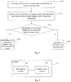
- Fig. 7 is a flow diagram of a method of integrity check provided by an embodiment of the present disclosure. As shown in Fig.
- the method includes: S701, receiving, by the terminal, user plane data transmitted by the network-side equipment; S702, performing, by the terminal, the integrity check on the user plane data based on the user-plane integrity check configuration information; S703, determining, by the terminal, whether the user plane data fails the integrity check, if so, the process proceeds to S704, otherwise, the process proceeds to S705; S704, performing, by the terminal, an integrity check failure processing process; and S705, acquiring, by the terminal, the user plane data.
- the integrity check failure process may be agreed upon in advance by the terminal and the network-side equipment, set by the terminal itself, or configured for the terminal by the network-side equipment.
- the integrity check process performed by the terminal may have two possible implementations.
- the terminal when the terminal determines that the user plane data fails the integrity check, the terminal performs the integrity check failure process. That is, the terminal performs the integrity check failure process once the integrity check fails.
- the network-side equipment before the terminal performs the integrity check, transmits a failure processing activation message to the terminal.
- the failure processing activation message is configured to instruct the terminal to start the integrity check failure processing process upon failure of the integrity check.
- the terminal will not perform the subsequent integrity check failure processing process. If the terminal has received the failure processing activation message, then after the terminal determines that the user plane data fails the integrity check, the terminal will perform the subsequent integrity check failure processing process.
- the terminal if the user plane data fails the integrity check, performs at least one of the following steps: transmitting, by the PDCP layer of the terminal, an integrity check failure notification message to the RRC layer of the terminal; discarding, by the terminal, the user plane data; transmitting, by the terminal, the integrity check failure notification message to the network-side equipment; releasing, by the terminal, the RRC connection with the network-side equipment; triggering, by the terminal, a radio link failure (RLF) mechanism; releasing, by the terminal, a DRB configuration of the network-side equipment.
- RLF radio link failure
- the integrity check failure processing process includes at least one of the steps described above.
- the PDCP layer of the terminal performs the integrity check on the user plane data.
- the PDCP layer of the terminal transmits an integrity check failure notification message to the RRC layer and discards the user plane data.
- the terminal may also transmit an integrity check failure notification message to the network-side equipment.
- the integrity check failure message involved in this embodiment may carry an identifier of the DRB that fails the integrity check.
- the network-side equipment may reconfigure the DRB for the terminal based on the identifier of the DRB that fails the integrity check.
- the terminal may also release the RRC connection with the network-side equipment and transmit a notification message that the terminal has released the RRC connection to the network-side equipment. During a subsequent processing process, the terminal may also re-establish the RRC connection with the network-side equipment.
- the terminal may also trigger a radio link failure (RLF) mechanism. After triggering the RLF mechanism, the terminal re-establishes the RRC within a specified time period. If the re-establishment fails within the specified time period, the terminal may initiate an RRC establishment request subsequently.
- RLF radio link failure
- the terminal may also release the DRB configuration of the network-side equipment.
- the network-side equipment configures an available DRB for the terminal for user plane data transmission.
- the terminal may release the DRB configuration configured by the network-side equipment for the terminal.
- the integrity check failure process may be selected flexibly according to different system architectures and different scenarios.
- the user-plane integrity check configuration information further includes third indication information configured to instruct the terminal to perform the integrity check on the received user plane data transmitted by another network-side equipment.
- the network-side equipment in the LTE transmits the user-plane integrity check configuration information to the terminal.
- the user-plane integrity check configuration information includes first indication information or second indication information described above.
- the user-plane integrity check configuration information further includes third indication information. That is, the network-side equipment in the LTE also instructs the terminal to perform integrity check on the received user plane data transmitted by the network-side equipment in the new radio access network. The process of integrity check performed by the terminal on the user plane data of the new radio access network is the same as the process of integrity check performed by the terminal on the user plane data of the LTE.
- the network-side equipment (the network-side equipment in the LTE network) transmits a configuration done notification message to the other network-side equipment (the network-side equipment in the new radio access network).
- the configuration done notification message is configured to notify the other network-side equipment that the user-plane integrity check configuration information transmitted to the terminal by the network-side equipment is applicable to the other network-side equipment.
- the other network-side equipment does not have to transmit the user-plane integrity check configuration information to the terminal.
- the terminal operates in a dual connectivity (DC) system and the network-side equipment in this embodiment is a secondary node (SN) in the DC system. If the user plane data fails the integrity check, the terminal transmits integrity check failure information to the master node (MN) in the DC system.
- DC dual connectivity
- MN master node
- the terminal may transmit integrity check failure information to the network-side equipment and/or another network-side equipment.
- the integrity check failure information includes the identifier of the network-side equipment.
- the network-side equipment in the new radio access network acts as the secondary node and the network-side equipment in the LTE network acts as the master node
- the terminal may transmit the user-plane-data integrity check failure information with the identifier of the secondary node (SN) to the master node rather than transmitting the integrity check failure information to the secondary node.
- the master node may disconnect from the secondary node (SN) and re-establish a connection with a new secondary node (SN).
- Another possible scenario may be a multi-connectivity system as shown in Fig. 2 , or a carrier aggregation (CA) scenario.
- CA carrier aggregation
- the carrier corresponding to the primary cell (Pcell) is referred to as a primary component carrier (PCC) or a primary carrier; and the carrier corresponding to the secondary cell (Scell) is referred to as a secondary component carrier (SCC) or a secondary carrier.
- PCC primary component carrier
- SCC secondary component carrier
- This embodiment presents illustratively a scenario including a primary cell, a primary secondary cell, and a secondary cell. For other scenarios including a primary cell and/or a primary secondary cell and a secondary cell, this embodiment is also applicable.
- the terminal When the terminal operates in a primary cell in a dual connectivity (DC) system or a carrier aggregation (CA) system, if the user plane data fails the integrity check, then the PDCP layer of the terminal transmits an integrity check failure notification message to the RRC layer, the terminal discards the user plane data; the terminal releases the RRC connection with the network-side equipment or triggers the radio link failure (RLF) mechanism.
- DC dual connectivity
- CA carrier aggregation
- the terminal When the terminal operates in a secondary cell in a dual connectivity (DC) system or a carrier aggregation (CA) system, if the user plane data fails the integrity check, then the terminal releases the data radio bearer (DRB) configuration of the secondary cell or all secondary cells, or stops using the DRB of the secondary cell or all secondary cells.
- DC dual connectivity
- CA carrier aggregation
- the primary cell is responsible for the RRC between the network-side equipment and the terminal, while the secondary cell is configured to provide additional radio resources, with no RRC communication between the secondary cell and the terminal. Therefore, when the terminal is located in the secondary cell described above, if the integrity check performed by the terminal fails, the terminal may not perform the process of releasing the RRC connection with the network-side equipment and triggering the RLF mechanism as described above.
- the network-side equipment When the terminal is performing the process of transmitting the integrity check failure notification message to the network-side equipment, and after the terminal transmits the integrity check failure notification message to the network-side equipment, the network-side equipment transmits RRC reconfiguration information to the terminal.
- the RRC reconfiguration message includes new user-plane-data integrity check configuration information, and the RRC reconfiguration message may also include other configuration information. There is no particular limitation in this embodiment in this respect.
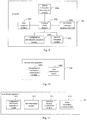
- Fig. 8 is a schematic structural diagram of a terminal provided by an embodiment of the present disclosure.
- a terminal 80 includes a data reception module 801 and an integrity check module 802.
- the data reception module 801 is configured to receive user plane data transmitted by the network-side equipment and the integrity check module 802 is configured to perform an integrity check on the user plane data based on user-plane integrity check configuration information.
- the user plane data is carried on the data radio bearer (DRB).
- the user-plane integrity check configuration information includes first indication information configured to indicate a DRB corresponding to the integrity check.
- the integrity check module is specifically configured to perform integrity check on the user plane data carried on the DRB indicated by the first indication information.
- the integrity check module 802 is specifically configured to: if the user plane data carried on at least one of DRBs indicated by the first indication information fails the integrity check, then determine that the user plane data fails the integrity check.
- the integrity check module 802 is specifically configured to: if at least one of data packets carried on the DRB fails the integrity check, determine that the user plane data carried on the DRB fails the integrity check; or if a ratio of the number of data packets carried on the DRB that fail the integrity check to the number of received data packets carried on the DRB exceeds a preset threshold, determine that the user plane data carried on the DRB fails the integrity check; or if the number of data packets carried on the DRB that fail the integrity check exceeds a preset number, determine that the user plane data carried on the DRB fails the integrity check; or if the number of data packets carried on the DRB that fail the integrity check exceeds a preset number in a preset duration, determine that the user plane data carried on the DRB fails the integrity check; or if the number of consecutive data packets carried on the DRB that fail the integrity check exceeds a preset number, determine that the user plane data carried on the DRB fails the integrity check.
- the user-plane integrity check configuration information includes second indication information configured to instruct the terminal to perform the integrity check on all the user plane data received.
- the integrity check module 802 is specifically configured to perform the integrity check on all the user plane data received by the terminal based on the second indication information.
- the integrity check module 802 is specifically configured to: if at least one of data packets of the user plane data fails the integrity check, determine that the user plane data fails the integrity check; or if a ratio of the number of data packets of the user plane data that fail the integrity check to the number of received data packets exceeds a preset threshold, determine that the user plane data fails the integrity check; or if the number of data packets of the user plane data that fail the integrity check exceeds a preset number, determine that the user plane data fails the integrity check; or if the number of data packets of the user plane data that fail the integrity check exceeds a preset number in a preset duration, determine that the user plane data fails the integrity check; or if the number of consecutive data packets of the user plane data that fail the integrity check exceeds a preset number, determine that the user plane data fails the integrity check.
- the data packet includes protocol data unit (PDU) and/or service data unit (SDU) of a packet data convergence protocol (PDCP) layer, a radio link control (RLC) layer and/or a media access control (MAC) layer.
- PDU protocol data unit
- SDU service data unit
- PDCP packet data convergence protocol
- RLC radio link control
- MAC media access control
- the user-plane integrity check configuration information further includes a determination criterion as to whether the user plane data fails the integrity check.
- the terminal according to this embodiment may perform the method shown in the embodiment described above and has similar implementation principles and technical effects and will not be described again here in this embodiment.
- Fig. 9 is a schematic structural diagram of a terminal provided by an embodiment of the present disclosure.
- the terminal in this embodiment further includes: a process execution module 803, an activation message reception module 804, a configuration information reception module 805, and a failure information transmission module 806.
- the process execution module 803 is configured to execute at least one of the following steps if the user plane data fails the integrity check: transmitting an integrity check failure notification message to the radio resource control (RRC) layer; discarding the user plane data; transmitting the integrity check failure notification message to the network-side equipment; releasing the RRC connection with the network-side equipment; triggering a radio link failure (RLF) mechanism; releasing the DRB configuration of the network-side equipment.
- RRC radio resource control
- the user plane data is carried on the Data Radio Bearer (DRB) and the integrity check failure notification message includes the identifier of the DRB that fails the integrity check.
- DRB Data Radio Bearer
- the activation message reception module 804 is configured to: before the integrity check module performs the integrity check on the user plane data based on the user-plane integrity check configuration information, receive the failure processing activation message transmitted by the network-side equipment.
- the configuration information reception module 805 is configured to: before the integrity check module performs the integrity check on the user plane data based on the user-plane integrity check configuration information, receive the user-plane-data integrity check configuration information transmitted by the network-side equipment.
- the terminal operates in a primary cell in a dual connectivity (DC) system or a carrier aggregation (CA) system
- the integrity check module 802 is further configured to: if the user plane data fails the integrity check, transmit an integrity check failure notification message to the RRC layer, discard the user plane data; release the RRC connection with the network-side equipment or trigger the radio link failure (RLF) mechanism.
- DC dual connectivity
- CA carrier aggregation
- the terminal operates in a secondary cell in a dual connectivity (DC) system or a carrier aggregation (CA) system
- the integrity check module 802 is further configured to: if the user plane data fails the integrity check, release the data radio bearer (DRB) configuration of the secondary cell or all secondary cells, or stop using the DRB of the secondary cell or all secondary cells.
- DC dual connectivity
- CA carrier aggregation
- the terminal operates in a dual connectivity (DC) system and the network-side equipment acts as the secondary node (SN) in the DC system.
- the failure information transmission module 806 is configured to: if the user plane data fails the integrity check, transmit integrity check failure information to the master node (MN) in the DC system.
- the integrity check failure information includes the identifier of the network-side equipment.
- the terminal operates in a dual connectivity (DC) system
- the user-plane-data integrity check configuration information further includes third indication information configured to instruct the terminal to perform the integrity check on the received user plane data transmitted by another network-side equipment.
- DC dual connectivity
- the user-plane integrity check configuration information further includes fourth indication information configured to indicate the integrity check algorithm corresponding to the integrity check performed on the user plane data by the terminal.
- the terminal provided by this embodiment may perform the method shown in the embodiment described above and has similar implementation principles and technical effects and will not be described again here in this embodiment.
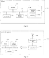
- Fig. 10 is a schematic structural diagram of network-side equipment provided by an embodiment of the present disclosure.
- the network-side equipment 100 includes a configuration information transmission module 1001 and a data transmission module 1002.
- the configuration information transmission module 1001 is configured to transmit user-plane-data integrity check configuration information to the terminal.
- the user-plane-data integrity check configuration information is configured to instruct the terminal to perform the integrity check on the user plane data received from the network-side equipment.
- the data transmission module 1002 is configured to transmit the user plane data to the terminal.
- the user plane data is carried on the data radio bearer (DRB).
- the user-plane integrity check configuration information includes first indication information configured to indicate a DRB corresponding to the integrity check.
- the user-plane integrity check configuration information further includes a first determination criterion as to whether the user plane data fails the integrity check.
- the first determination criterion as to whether the user plane data fails the integrity check includes: if the user plane data carried on at least one of DRBs indicated by the first indication information fails the integrity check, then the user plane data fails the integrity check.
- that the user plane data carried on the DRB fails the integrity check includes: if at least one of data packets carried on the DRB fails the integrity check, then the user plane data carried on the DRB fails the integrity check; or if a ratio of the number of data packets carried on the DRB that fail the integrity check to the number of received data packets carried on the DRB exceeds a preset threshold, then the user plane data carried on the DRB fails the integrity check; or if the number of data packets carried on the DRB that fail the integrity check exceeds a preset number, then the user plane data carried on the DRB fails the integrity check; or if the number of data packets carried on the DRB that fail the integrity check exceeds a preset number in a preset duration, then the user plane data carried on the DRB fails the integrity check; or if the number of consecutive data packets carried on the DRB that fail the integrity check exceeds a preset number, then the user plane data carried on the DRB fails the integrity check.
- the user-plane integrity check configuration information includes second indication information configured to instruct the terminal to perform the integrity check on all the user plane data received.
- the user-plane integrity check configuration information further includes a second determination criterion as to whether the user plane data fails the integrity check.
- the second determination criterion as to whether the user plane data fails the integrity check includes: if at least one of data packets of the user plane data fails the integrity check, then the user plane data fails the integrity check; or if a ratio of the number of data packets of the user plane data that fail the integrity check to the number of received data packets exceeds a preset threshold, then the user plane data fails the integrity check; or if the number of data packets of the user plane data that fail the integrity check exceeds a preset number, then the user plane data fails the integrity check; or if the number of data packets of the user plane data that fail the integrity check exceeds a preset number in a preset duration, then the user plane data fails the integrity check; or if the number of consecutive data packets of the user plane data that fail the integrity check exceeds a preset number, then the user plane data fails the integrity check.
- the data packet includes protocol data unit (PDU) and/or service data unit (SDU) of a packet data convergence protocol (PDCP) layer, a radio link control (RLC) layer and/or a media access control (MAC) layer.
- PDU protocol data unit
- SDU service data unit
- PDCP packet data convergence protocol
- RLC radio link control
- MAC media access control
- the network-side equipment provided by this embodiment may perform the method shown in the embodiment described above and has similar implementation principles and technical effects and will not be described again here in this embodiment.
- Fig. 11 is a schematic structural diagram of network-side equipment provided by an embodiment of the present disclosure. As shown in Fig. 11 , on the basis of the embodiment shown in Fig. 10 , the network-side equipment in this embodiment further includes an activation message transmission module 1003 and a failure information reception module 1004. The activation message transmission module 1003 is configured to transmit a failure processing activation message to the terminal.
- the network-side equipment operates in a dual connectivity (DC) system and the network-side equipment acts as the master node (MN) in the DC system.
- the failure information reception module 1004 is configured to receive the integrity check failure information transmitted by the terminal.
- the integrity check failure information includes the identifier of the secondary node corresponding to the failure of the integrity check in the DC system.
- the network-side equipment operates in a dual connectivity (DC) system and the user-plane integrity check configuration information further includes third indication information configured to instruct the terminal to perform the integrity check on the received user plane data transmitted by another network-side equipment.
- DC dual connectivity
- the user-plane integrity check configuration information further includes fourth indication information configured to indicate the integrity check algorithm corresponding to the integrity check performed on the user plane data by the terminal.
- the network-side equipment provided by this embodiment may perform the method shown in the embodiment described above and has similar implementation principles and technical effects and will not be described again here in this embodiment.
- Fig. 12 is a schematic structural diagram of a terminal provided by another embodiment of the present disclosure.
- a terminal 1200 as shown in Fig. 12 includes: at least one processor 1201, a storage 1202, at least one network interface 1204, and a user interface 1203.
- Various components in the terminal 1200 are coupled to one another via a bus system 1205.
- the bus system 1205 is configured to enable connection communication between these components.
- the bus system 1205 also includes a power bus, a control bus, and a status signal bus. However, for the sake of clarity, all the buses are denoted collectively as the bus system 1205 in Fig. 11 .
- the user interface 1203 may include a display, a keyboard, or a clicking device such as a mouse, a trackball, a touch pad, or a touch screen and the like.
- the storage 1202 in embodiments of the present disclosure may be a volatile storage or a non-volatile storage, or may include both a volatile storage and a non-volatile storage.
- the non-volatile storage may be a read-only memory (ROM), a programmable ROM (PROM), an erasable PROM (EPROM), an electrically EPROM (EEPROM), or a flash memory.
- the volatile storage may be a random access memory (RAM) that acts as an external cache.
- RAM random access memory
- DRAM dynamic RAM
- SDRAM synchronous DRAM
- DDRSDRAM double data rate SDRAM
- ESDRAM enhanced SDRAM
- SLDRAM synchlink DRAM
- DRRAM direct rambus RAM
- the storage 1202 stores the following elements, executable modules, or data structures, or the subsets thereof, or the extension sets thereof: an operating system 12021 and an application 12022.
- the operating system 12021 includes various system programs, such as a framework layer program, a core library layer program, or a driver layer program and the like, and is configured to implement various basic services and handle hardware-based tasks.
- the application 12022 includes various applications, such as a media player, a browser, and the like, and is configured to implement various application services. Programs for implementing the method of the embodiments of the present disclosure may be included in the application 12022.
- the processor 1201 by calling programs or instructions stored in the storage 1202, specifically programs or instructions stored in the application 12022, the processor 1201 is configured to perform the integrity check on the user plane data transmitted by the network-side equipment based on the user-plane integrity check configuration information after the network interface 1204 receives the user plane data.
- the method disclosed in the embodiments of the present disclosure described above may be applied to or implemented by the processor 1201.
- the processor 1201 may be an integrated circuit chip with signal processing capabilities. During implementation, various steps of the method described above may be achieved in form of hardware by integrated logical circuits in the processor 1201, or in form of software by instructions..
- the processor 1201 may be a general-purpose processor, a digital signal processor (DSP), an application specific integrated circuit (ASIC), a field programmable gate array (FPGA) or other programmable logic devices, discrete gates or transistor logic devices, or discrete hardware components.
- DSP digital signal processor
- ASIC application specific integrated circuit
- FPGA field programmable gate array
- the methods, steps, and logical block diagrams disclosed in embodiments of the present disclosure may be implemented or performed.
- the general-purpose processor may be a micro-processor or the processor may be any conventional processor or the like.
- the steps of the method disclosed in connection with the embodiments of the present disclosure may be directly embodied in form of hardware by coding processor or implemented by the combination of hardware in the coding processor and software module.
- the software module may reside in a storage medium well-known in the art, such as a random access memory, a flash memory, a read-only memory, a programmable read-only memory or an electrically erasable programmable memory, or a register.
- the storage medium resides in the storage 1202, and the processor 1201 reads the information in the storage 1202 and completes the steps of the method described above in combination with hardware of the processor 1201.
- the embodiments described in the present disclosure may be implemented in hardware, software, firmware, middleware, microcode, or a combination thereof.
- the processing unit may be implemented in one or more application specific integrated circuits (ASIC), a digital signal processor (DSP), a DSP device (DSPD), a programmable logic device (PLD), a field-programmable gate array (FPGA), a general-purpose processor, a controller, a microcontroller, a microprocessor, other electronic units for performing the functions described in the present disclosure, or combinations thereof.
- ASIC application specific integrated circuits
- DSP digital signal processor
- DSPD DSP device
- PLD programmable logic device
- FPGA field-programmable gate array
- the techniques described in the embodiments of the present disclosure may be implemented by modules (e.g., processes, functions, etc.) that perform the functions described in the embodiments of the present disclosure.
- the software codes may be stored in a storage and executed by a processor.
- the storage may be implemented internal or external to the processor.
- the processor 1201 may call programs or instructions stored in the storage 1202 to execute the method performed by the terminal in the method embodiment described above.
- the implementation principles and technical effects are similar, and will not be described again here in this embodiment.
- Fig. 13 is a schematic structural diagram of network-side equipment provided by another embodiment of the present disclosure.
- the network-side equipment 1300 includes an antenna 1301, a radio frequency unit 1302, and a baseband unit 1303.
- the antenna 1301 is connected to the radio frequency unit 1302.
- the radio frequency unit 1302 receives information via the antenna 1301 and transmits the information received to the baseband unit 1303 for processing.
- the baseband unit 1303 processes the information to be transmitted and transmits it to the radio frequency unit 1302.
- the radio frequency unit 1302 processes the received information and transmits it out via the antenna 1301.
- the frequency band processing unit may reside in the baseband unit 1303.
- the method executed by the network-side equipment in the above embodiment may be implemented in the baseband unit 1303.
- the baseband unit 1303 includes a processor 13031 and a storage 13032.
- the baseband unit 1303 may, for example, include at least one baseband processing board having multiple chips arranged thereon, as shown in Fig. 12 .
- One of the chips is, for example, the processor 13031 that is connected to the storage 13032 to call the program in the storage 13032 so as to execute the operations of the network-side equipment shown in the above method embodiment.
- the baseband unit 1303 may further include a network interface 13033 configured to exchange information with the radio frequency unit 1302.
- the interface is, for example, a common public radio interface (CPRI).
- CPRI common public radio interface
- the processor herein may be one processor or refer to multiple processing elements collectively.
- the processor may be a CPU, or may be an ASIC, or one or more integrated circuits configured to implement the method performed by the network-side equipment, such as one or more DSPs, or one or more FPGAs.
- the storage element may be one storage or may refer to multiple storage elements collectively.
- the storage 13032 may be a volatile storage or a non-volatile storage, or may include both a volatile storage and a non-volatile storage.
- the non-volatile storage may be an ROM, a PROM, an EPROM, an EEPROM or a flash memory.
- the volatile storage may be an RAM and is used as an external cache.
- various forms of RAMs are usable, such as an SRAM, a DRAM, a SDRAM, a DDRSDRAM, an ESDRAM, an SLDRAM, and a DRRAM.
- the storage 13032 described in the embodiments of the present disclosure intends to include, without limitation, these and any other suitable types of storages.
- the processor 13031 may call programs stored in the storage 13032 to execute the method performed by the network-side equipment in the embodiment described above.
- the implementation principles and technical effects are similar, and will not be described again here in this embodiment.
- the disclosed apparatuses and methods may be implemented in other ways.
- the apparatus embodiments described above are only exemplary.
- the units are divided merely in terms of their logic functions. In actual implementation, however, there may be other division methods.
- multiple units or components may be combined or integrated into another system, or some features may be ignored or not implemented.
- the displayed or discussed mutual couplings or direct couplings or communication connections may be implemented through some interfaces.
- the indirect couplings or communication connections between the devices or units may be implemented in electrical, mechanical, or other forms.
- the unit described as separate parts may be or may not be physically separated, and the parts shown as a unit may be or may not be a physical unit, i.e., they may be located in one place or may be distributed over multiple network units. Some or all of these units may be selected according to actual needs to achieve the purpose of the solution of the embodiment.
- various functional units in the embodiments of the present disclosure may be integrated into one processing unit, or each of the units may exist alone physically.
- two or more functional units may be integrated into one unit.
- the functions may be stored in a computer-readable storage medium.
- the software product is stored in a storage medium, and includes several instructions for instructing a computer device (which may be a personal computer, a server, or a network equipment) to perform all or a part of the steps of the methods described in the embodiments of the disclosure.
- the foregoing storage medium includes any medium that can store program code, such as a universal serial bus (USB) flash drive, a removable hard disk, an ROM, an RAM, a magnetic disk, or an optical disc.
- USB universal serial bus
- all or some of the steps to implement the various method embodiments described above may be executed by hardware associated with program instructions.
- the aforementioned program may be stored in a computer-readable storage medium.
- the program when executed, performs the steps of the method embodiments described above; and the aforementioned storage medium includes various media that may store program codes, such as an ROM, an RAM, a magnetic disk, or an optical disc.
Landscapes
- Engineering & Computer Science (AREA)
- Computer Security & Cryptography (AREA)
- Computer Networks & Wireless Communication (AREA)
- Signal Processing (AREA)
- Computer Hardware Design (AREA)
- Computing Systems (AREA)
- General Engineering & Computer Science (AREA)
- Mobile Radio Communication Systems (AREA)
Applications Claiming Priority (2)
| Application Number | Priority Date | Filing Date | Title |
|---|---|---|---|
| CN201710297656.8A CN108810899A (zh) | 2017-04-28 | 2017-04-28 | 完整性检测方法、终端及网络侧设备 |
| PCT/CN2018/084820 WO2018196852A1 (fr) | 2017-04-28 | 2018-04-27 | Procédé de détection d'intégrité, terminal et dispositif réseau |
Publications (3)
| Publication Number | Publication Date |
|---|---|
| EP3618480A4 EP3618480A4 (fr) | 2020-03-04 |
| EP3618480A1 true EP3618480A1 (fr) | 2020-03-04 |
| EP3618480B1 EP3618480B1 (fr) | 2022-03-23 |
Family
ID=63918853
Family Applications (1)
| Application Number | Title | Priority Date | Filing Date |
|---|---|---|---|
| EP18791933.7A Active EP3618480B1 (fr) | 2017-04-28 | 2018-04-27 | Procédé de détection d'intégrité, terminal et dispositif réseau |
Country Status (5)
| Country | Link |
|---|---|
| US (1) | US11910195B2 (fr) |
| EP (1) | EP3618480B1 (fr) |
| CN (1) | CN108810899A (fr) |
| ES (1) | ES2911555T3 (fr) |
| WO (1) | WO2018196852A1 (fr) |
Families Citing this family (7)
| Publication number | Priority date | Publication date | Assignee | Title |
|---|---|---|---|---|
| WO2020088819A1 (fr) * | 2018-11-01 | 2020-05-07 | Telefonaktiebolaget Lm Ericsson (Publ) | Traitement d'ambiguïté d'échec de rétablissement |
| CN111315039B (zh) * | 2018-12-24 | 2023-02-24 | 维沃移动通信有限公司 | 一种完整性保护失败的处理方法及终端 |
| US11677104B2 (en) * | 2020-01-30 | 2023-06-13 | Sensata Technologies, Inc. | Functional safety in a battery management system |
| CN113381966B (zh) * | 2020-03-09 | 2023-09-26 | 维沃移动通信有限公司 | 信息上报方法、信息接收方法、终端及网络侧设备 |
| DE102020111450A1 (de) * | 2020-04-27 | 2021-10-28 | Bayerische Motoren Werke Aktiengesellschaft | Erkennen von Fehlern in einem Computernetzwerk |
| CN113691986B (zh) * | 2020-05-15 | 2023-09-12 | 维沃移动通信有限公司 | 完整性保护失败的处理方法、装置和用户设备 |
| CN114513319B (zh) * | 2020-10-28 | 2023-11-07 | 展讯半导体(南京)有限公司 | 数据处理方法及装置 |
Family Cites Families (21)
| Publication number | Priority date | Publication date | Assignee | Title |
|---|---|---|---|---|
| CN101111033B (zh) | 2007-08-31 | 2013-10-02 | 华为技术有限公司 | 串话检测方法、网络侧设备及终端 |
| CN102036256B (zh) | 2009-09-28 | 2013-03-20 | 华为技术有限公司 | 数据传输方法、装置及系统 |
| KR101831448B1 (ko) * | 2010-02-02 | 2018-02-26 | 엘지전자 주식회사 | 이동 통신 시스템에서 pdcp 기능을 선택적으로 적용하는 방법 |
| CN102149088A (zh) * | 2010-02-09 | 2011-08-10 | 工业和信息化部电信传输研究所 | 一种保护移动用户数据完整性的方法 |
| CN102487507B (zh) | 2010-12-01 | 2016-01-20 | 中兴通讯股份有限公司 | 一种实现完整性保护的方法及系统 |
| DK2649740T3 (en) | 2010-12-10 | 2015-03-23 | Ericsson Telefon Ab L M | ENABLE AND DISABLE INTEGRITY PROTECTION FOR DATA CARRIERS |
| CN102547687B (zh) | 2010-12-23 | 2015-06-17 | 上海贝尔股份有限公司 | 无线通信网络中对数据包进行处理的方法及装置 |
| CN102158901B (zh) | 2011-02-16 | 2014-01-08 | 大唐移动通信设备有限公司 | 网络侧进行终端操作配置的方法及网络侧装置 |
| CN102740414A (zh) | 2011-03-31 | 2012-10-17 | 中国移动通信集团公司 | 一种选择通信网络的方法、终端及网络侧设备 |
| CN102142942B (zh) * | 2011-04-01 | 2017-02-08 | 中兴通讯股份有限公司 | 一种中继节点系统中的数据处理方法及系统 |
| CN103458475A (zh) | 2012-05-31 | 2013-12-18 | 中兴通讯股份有限公司 | Hrpd和lte间移动鲁棒性检测方法、终端和网络侧 |
| CN103781130A (zh) | 2012-10-25 | 2014-05-07 | 华为技术有限公司 | 接入网络的方法、网络侧设备与终端 |
| EP2770796B1 (fr) * | 2013-02-22 | 2016-04-27 | HTC Corporation | Procédé pour des communications simultanées avec des stations de base multiples et dispositif de communication associé |
| ES2769858T3 (es) * | 2013-04-01 | 2020-06-29 | Innovative Sonic Corp | Método y aparato para añadir células de servicio en un sistema de comunicación inalámbrica |
| MX354148B (es) * | 2013-07-03 | 2018-02-15 | Interdigital Patent Holdings Inc | Mejoramientos epc para servicios de proximidad. |
| CN104349312B (zh) * | 2013-08-02 | 2019-01-29 | 上海诺基亚贝尔股份有限公司 | 用于支持双连接的安全处理的方法 |
| CN104936169B (zh) * | 2014-03-18 | 2018-09-04 | 中国移动通信集团公司 | 一种安全验证处理方法、装置、终端及基站 |
| CN104936173B (zh) * | 2014-03-18 | 2022-02-25 | 华为技术有限公司 | 密钥生成方法、主基站、辅基站及用户设备 |
| CN106375989B (zh) * | 2015-07-20 | 2019-03-12 | 中兴通讯股份有限公司 | 实现接入层安全的方法及用户设备和无线接入小节点 |
| US10368238B2 (en) * | 2015-12-01 | 2019-07-30 | Htc Corporation | Device and method of handling data transmission/reception for dual connectivity |
| CN108617029B (zh) * | 2016-12-30 | 2023-05-12 | 夏普株式会社 | 无线承载配置方法、及相应的ue和基站 |
-
2017
- 2017-04-28 CN CN201710297656.8A patent/CN108810899A/zh active Pending
-
2018
- 2018-04-27 ES ES18791933T patent/ES2911555T3/es active Active
- 2018-04-27 EP EP18791933.7A patent/EP3618480B1/fr active Active
- 2018-04-27 US US16/608,276 patent/US11910195B2/en active Active
- 2018-04-27 WO PCT/CN2018/084820 patent/WO2018196852A1/fr not_active Ceased
Also Published As
| Publication number | Publication date |
|---|---|
| US11910195B2 (en) | 2024-02-20 |
| WO2018196852A1 (fr) | 2018-11-01 |
| EP3618480A4 (fr) | 2020-03-04 |
| EP3618480B1 (fr) | 2022-03-23 |
| US20200092726A1 (en) | 2020-03-19 |
| CN108810899A (zh) | 2018-11-13 |
| ES2911555T3 (es) | 2022-05-19 |
Similar Documents
| Publication | Publication Date | Title |
|---|---|---|
| EP3618480B1 (fr) | Procédé de détection d'intégrité, terminal et dispositif réseau | |
| US12185101B2 (en) | Multi-RAT access stratum security | |
| US20230354454A1 (en) | Re-Establishment of Component Carriers in a Wireless Communication System | |
| CN101651899B (zh) | Lte rrc连接重建立请求方法、原因值设置方法及终端 | |
| CN107113291B (zh) | 演进的数据压缩方案信令 | |
| CN104170422B (zh) | 在lte接入网中集成wifi无线电接口的安全性解决方法及装置 | |
| CN116250342A (zh) | 针对小数据传输的空闲/非活动移动性 | |
| EP3624530A1 (fr) | Procédé de traitement d'informations et appareil associé | |
| US20190174366A1 (en) | Methods, devices and nodes for resuming a radio connection for a wireless device | |
| CN108271276B (zh) | 处理系统间移动中的新无线连接的装置及方法 | |
| WO2019095885A1 (fr) | Procédé d'accès au réseau, dispositif terminal et dispositif réseau | |
| CN116017767A (zh) | 一种通信方法及无线通信装置 | |
| KR20130093774A (ko) | Pdcp 패킷 전송 방법 | |
| CN108633003A (zh) | 一种资源分配方法和装置以及终端设备 | |
| CN110915254A (zh) | 执行测量的方法以及支持该方法的装置 | |
| WO2013102446A1 (fr) | Procédé et dispositif de transmission de données | |
| US11218929B2 (en) | Information transmission method and apparatus and communication system | |
| WO2019140663A1 (fr) | Procédé de commutation de partie de largeur de bande basé sur le temps, dispositif terminal et dispositif de réseau | |
| US20160302100A1 (en) | Techniques for retransmissions during bursty traffic | |
| WO2019192458A1 (fr) | Procédé et appareil de communication | |
| US20240357690A1 (en) | Method and apparatus for transceiving information, and communication system | |
| CN116636299A (zh) | 一种处理无线链路失败的方法及装置、通信设备 | |
| CN110754137A (zh) | 处理rrc连接释放 | |
| WO2015003353A1 (fr) | Procédé et appareil de communication | |
| US10560870B2 (en) | Device and method of handling cellular-WLAN aggregation |
Legal Events
| Date | Code | Title | Description |
|---|---|---|---|
| STAA | Information on the status of an ep patent application or granted ep patent |
Free format text: STATUS: THE INTERNATIONAL PUBLICATION HAS BEEN MADE |
|
| PUAI | Public reference made under article 153(3) epc to a published international application that has entered the european phase |
Free format text: ORIGINAL CODE: 0009012 |
|
| STAA | Information on the status of an ep patent application or granted ep patent |
Free format text: STATUS: REQUEST FOR EXAMINATION WAS MADE |
|
| 17P | Request for examination filed |
Effective date: 20191028 |
|
| A4 | Supplementary search report drawn up and despatched |
Effective date: 20200116 |
|
| AK | Designated contracting states |
Kind code of ref document: A1 Designated state(s): AL AT BE BG CH CY CZ DE DK EE ES FI FR GB GR HR HU IE IS IT LI LT LU LV MC MK MT NL NO PL PT RO RS SE SI SK SM TR |
|
| AX | Request for extension of the european patent |
Extension state: BA ME |
|
| DAV | Request for validation of the european patent (deleted) | ||
| DAX | Request for extension of the european patent (deleted) | ||
| RIN1 | Information on inventor provided before grant (corrected) |
Inventor name: YANG, XIAODONG |
|
| REG | Reference to a national code |
Ref country code: DE Ref legal event code: R079 Ref document number: 602018032684 Country of ref document: DE Free format text: PREVIOUS MAIN CLASS: H04W0012100000 Ipc: H04W0012102000 |
|
| GRAP | Despatch of communication of intention to grant a patent |
Free format text: ORIGINAL CODE: EPIDOSNIGR1 |
|
| STAA | Information on the status of an ep patent application or granted ep patent |
Free format text: STATUS: GRANT OF PATENT IS INTENDED |
|
| RIC1 | Information provided on ipc code assigned before grant |
Ipc: H04W 88/02 20090101ALN20211022BHEP Ipc: H04L 29/06 20060101ALI20211022BHEP Ipc: H04W 12/106 20210101ALI20211022BHEP Ipc: H04W 12/104 20210101ALI20211022BHEP Ipc: H04W 12/102 20210101AFI20211022BHEP |
|
| INTG | Intention to grant announced |
Effective date: 20211122 |
|
| GRAS | Grant fee paid |
Free format text: ORIGINAL CODE: EPIDOSNIGR3 |
|
| GRAA | (expected) grant |
Free format text: ORIGINAL CODE: 0009210 |
|
| STAA | Information on the status of an ep patent application or granted ep patent |
Free format text: STATUS: THE PATENT HAS BEEN GRANTED |
|
| AK | Designated contracting states |
Kind code of ref document: B1 Designated state(s): AL AT BE BG CH CY CZ DE DK EE ES FI FR GB GR HR HU IE IS IT LI LT LU LV MC MK MT NL NO PL PT RO RS SE SI SK SM TR |
|
| REG | Reference to a national code |
Ref country code: GB Ref legal event code: FG4D |
|
| REG | Reference to a national code |
Ref country code: CH Ref legal event code: EP |
|
| REG | Reference to a national code |
Ref country code: IE Ref legal event code: FG4D |
|
| REG | Reference to a national code |
Ref country code: DE Ref legal event code: R096 Ref document number: 602018032684 Country of ref document: DE |
|
| REG | Reference to a national code |
Ref country code: AT Ref legal event code: REF Ref document number: 1478269 Country of ref document: AT Kind code of ref document: T Effective date: 20220415 |
|
| REG | Reference to a national code |
Ref country code: NL Ref legal event code: FP |
|
| REG | Reference to a national code |
Ref country code: ES Ref legal event code: FG2A Ref document number: 2911555 Country of ref document: ES Kind code of ref document: T3 Effective date: 20220519 |
|
| REG | Reference to a national code |
Ref country code: LT Ref legal event code: MG9D |
|
| PG25 | Lapsed in a contracting state [announced via postgrant information from national office to epo] |
Ref country code: SE Free format text: LAPSE BECAUSE OF FAILURE TO SUBMIT A TRANSLATION OF THE DESCRIPTION OR TO PAY THE FEE WITHIN THE PRESCRIBED TIME-LIMIT Effective date: 20220323 Ref country code: RS Free format text: LAPSE BECAUSE OF FAILURE TO SUBMIT A TRANSLATION OF THE DESCRIPTION OR TO PAY THE FEE WITHIN THE PRESCRIBED TIME-LIMIT Effective date: 20220323 Ref country code: NO Free format text: LAPSE BECAUSE OF FAILURE TO SUBMIT A TRANSLATION OF THE DESCRIPTION OR TO PAY THE FEE WITHIN THE PRESCRIBED TIME-LIMIT Effective date: 20220623 Ref country code: LT Free format text: LAPSE BECAUSE OF FAILURE TO SUBMIT A TRANSLATION OF THE DESCRIPTION OR TO PAY THE FEE WITHIN THE PRESCRIBED TIME-LIMIT Effective date: 20220323 Ref country code: HR Free format text: LAPSE BECAUSE OF FAILURE TO SUBMIT A TRANSLATION OF THE DESCRIPTION OR TO PAY THE FEE WITHIN THE PRESCRIBED TIME-LIMIT Effective date: 20220323 Ref country code: BG Free format text: LAPSE BECAUSE OF FAILURE TO SUBMIT A TRANSLATION OF THE DESCRIPTION OR TO PAY THE FEE WITHIN THE PRESCRIBED TIME-LIMIT Effective date: 20220623 |
|
| REG | Reference to a national code |
Ref country code: AT Ref legal event code: MK05 Ref document number: 1478269 Country of ref document: AT Kind code of ref document: T Effective date: 20220323 |
|
| PG25 | Lapsed in a contracting state [announced via postgrant information from national office to epo] |
Ref country code: LV Free format text: LAPSE BECAUSE OF FAILURE TO SUBMIT A TRANSLATION OF THE DESCRIPTION OR TO PAY THE FEE WITHIN THE PRESCRIBED TIME-LIMIT Effective date: 20220323 Ref country code: GR Free format text: LAPSE BECAUSE OF FAILURE TO SUBMIT A TRANSLATION OF THE DESCRIPTION OR TO PAY THE FEE WITHIN THE PRESCRIBED TIME-LIMIT Effective date: 20220624 Ref country code: FI Free format text: LAPSE BECAUSE OF FAILURE TO SUBMIT A TRANSLATION OF THE DESCRIPTION OR TO PAY THE FEE WITHIN THE PRESCRIBED TIME-LIMIT Effective date: 20220323 |
|
| PG25 | Lapsed in a contracting state [announced via postgrant information from national office to epo] |
Ref country code: SM Free format text: LAPSE BECAUSE OF FAILURE TO SUBMIT A TRANSLATION OF THE DESCRIPTION OR TO PAY THE FEE WITHIN THE PRESCRIBED TIME-LIMIT Effective date: 20220323 Ref country code: SK Free format text: LAPSE BECAUSE OF FAILURE TO SUBMIT A TRANSLATION OF THE DESCRIPTION OR TO PAY THE FEE WITHIN THE PRESCRIBED TIME-LIMIT Effective date: 20220323 Ref country code: RO Free format text: LAPSE BECAUSE OF FAILURE TO SUBMIT A TRANSLATION OF THE DESCRIPTION OR TO PAY THE FEE WITHIN THE PRESCRIBED TIME-LIMIT Effective date: 20220323 Ref country code: PT Free format text: LAPSE BECAUSE OF FAILURE TO SUBMIT A TRANSLATION OF THE DESCRIPTION OR TO PAY THE FEE WITHIN THE PRESCRIBED TIME-LIMIT Effective date: 20220725 Ref country code: EE Free format text: LAPSE BECAUSE OF FAILURE TO SUBMIT A TRANSLATION OF THE DESCRIPTION OR TO PAY THE FEE WITHIN THE PRESCRIBED TIME-LIMIT Effective date: 20220323 Ref country code: CZ Free format text: LAPSE BECAUSE OF FAILURE TO SUBMIT A TRANSLATION OF THE DESCRIPTION OR TO PAY THE FEE WITHIN THE PRESCRIBED TIME-LIMIT Effective date: 20220323 Ref country code: AT Free format text: LAPSE BECAUSE OF FAILURE TO SUBMIT A TRANSLATION OF THE DESCRIPTION OR TO PAY THE FEE WITHIN THE PRESCRIBED TIME-LIMIT Effective date: 20220323 |
|
| PG25 | Lapsed in a contracting state [announced via postgrant information from national office to epo] |
Ref country code: PL Free format text: LAPSE BECAUSE OF FAILURE TO SUBMIT A TRANSLATION OF THE DESCRIPTION OR TO PAY THE FEE WITHIN THE PRESCRIBED TIME-LIMIT Effective date: 20220323 Ref country code: IS Free format text: LAPSE BECAUSE OF FAILURE TO SUBMIT A TRANSLATION OF THE DESCRIPTION OR TO PAY THE FEE WITHIN THE PRESCRIBED TIME-LIMIT Effective date: 20220723 Ref country code: AL Free format text: LAPSE BECAUSE OF FAILURE TO SUBMIT A TRANSLATION OF THE DESCRIPTION OR TO PAY THE FEE WITHIN THE PRESCRIBED TIME-LIMIT Effective date: 20220323 |
|
| REG | Reference to a national code |
Ref country code: CH Ref legal event code: PL |
|
| REG | Reference to a national code |
Ref country code: DE Ref legal event code: R097 Ref document number: 602018032684 Country of ref document: DE |
|
| REG | Reference to a national code |
Ref country code: BE Ref legal event code: MM Effective date: 20220430 |
|
| PLBE | No opposition filed within time limit |
Free format text: ORIGINAL CODE: 0009261 |
|
| STAA | Information on the status of an ep patent application or granted ep patent |
Free format text: STATUS: NO OPPOSITION FILED WITHIN TIME LIMIT |
|
| PG25 | Lapsed in a contracting state [announced via postgrant information from national office to epo] |
Ref country code: MC Free format text: LAPSE BECAUSE OF FAILURE TO SUBMIT A TRANSLATION OF THE DESCRIPTION OR TO PAY THE FEE WITHIN THE PRESCRIBED TIME-LIMIT Effective date: 20220323 Ref country code: LU Free format text: LAPSE BECAUSE OF NON-PAYMENT OF DUE FEES Effective date: 20220427 Ref country code: LI Free format text: LAPSE BECAUSE OF NON-PAYMENT OF DUE FEES Effective date: 20220430 Ref country code: DK Free format text: LAPSE BECAUSE OF FAILURE TO SUBMIT A TRANSLATION OF THE DESCRIPTION OR TO PAY THE FEE WITHIN THE PRESCRIBED TIME-LIMIT Effective date: 20220323 Ref country code: CH Free format text: LAPSE BECAUSE OF NON-PAYMENT OF DUE FEES Effective date: 20220430 |
|
| PG25 | Lapsed in a contracting state [announced via postgrant information from national office to epo] |
Ref country code: BE Free format text: LAPSE BECAUSE OF NON-PAYMENT OF DUE FEES Effective date: 20220430 |
|
| 26N | No opposition filed |
Effective date: 20230102 |
|
| PG25 | Lapsed in a contracting state [announced via postgrant information from national office to epo] |
Ref country code: IE Free format text: LAPSE BECAUSE OF NON-PAYMENT OF DUE FEES Effective date: 20220427 |
|
| PG25 | Lapsed in a contracting state [announced via postgrant information from national office to epo] |
Ref country code: SI Free format text: LAPSE BECAUSE OF FAILURE TO SUBMIT A TRANSLATION OF THE DESCRIPTION OR TO PAY THE FEE WITHIN THE PRESCRIBED TIME-LIMIT Effective date: 20220323 |
|
| P01 | Opt-out of the competence of the unified patent court (upc) registered |
Effective date: 20230704 |
|
| PG25 | Lapsed in a contracting state [announced via postgrant information from national office to epo] |
Ref country code: MK Free format text: LAPSE BECAUSE OF FAILURE TO SUBMIT A TRANSLATION OF THE DESCRIPTION OR TO PAY THE FEE WITHIN THE PRESCRIBED TIME-LIMIT Effective date: 20220323 Ref country code: CY Free format text: LAPSE BECAUSE OF FAILURE TO SUBMIT A TRANSLATION OF THE DESCRIPTION OR TO PAY THE FEE WITHIN THE PRESCRIBED TIME-LIMIT Effective date: 20220323 |
|
| PG25 | Lapsed in a contracting state [announced via postgrant information from national office to epo] |
Ref country code: HU Free format text: LAPSE BECAUSE OF FAILURE TO SUBMIT A TRANSLATION OF THE DESCRIPTION OR TO PAY THE FEE WITHIN THE PRESCRIBED TIME-LIMIT; INVALID AB INITIO Effective date: 20180427 |
|
| PG25 | Lapsed in a contracting state [announced via postgrant information from national office to epo] |
Ref country code: TR Free format text: LAPSE BECAUSE OF FAILURE TO SUBMIT A TRANSLATION OF THE DESCRIPTION OR TO PAY THE FEE WITHIN THE PRESCRIBED TIME-LIMIT Effective date: 20220323 |
|
| PG25 | Lapsed in a contracting state [announced via postgrant information from national office to epo] |
Ref country code: MT Free format text: LAPSE BECAUSE OF FAILURE TO SUBMIT A TRANSLATION OF THE DESCRIPTION OR TO PAY THE FEE WITHIN THE PRESCRIBED TIME-LIMIT Effective date: 20220323 |
|
| PGFP | Annual fee paid to national office [announced via postgrant information from national office to epo] |
Ref country code: DE Payment date: 20250305 Year of fee payment: 8 |
|
| PGFP | Annual fee paid to national office [announced via postgrant information from national office to epo] |
Ref country code: ES Payment date: 20250509 Year of fee payment: 8 |
|
| PGFP | Annual fee paid to national office [announced via postgrant information from national office to epo] |
Ref country code: GB Payment date: 20260312 Year of fee payment: 9 |
|
| PGFP | Annual fee paid to national office [announced via postgrant information from national office to epo] |
Ref country code: IT Payment date: 20260320 Year of fee payment: 9 |
|
| PGFP | Annual fee paid to national office [announced via postgrant information from national office to epo] |
Ref country code: NL Payment date: 20260317 Year of fee payment: 9 |
|
| PGFP | Annual fee paid to national office [announced via postgrant information from national office to epo] |
Ref country code: FR Payment date: 20260309 Year of fee payment: 9 |