EP3618700B1 - Vorrichtung und verfahren zur bestimmung eines blutdrucks einer person - Google Patents
Vorrichtung und verfahren zur bestimmung eines blutdrucks einer person Download PDFInfo
- Publication number
- EP3618700B1 EP3618700B1 EP17866379.5A EP17866379A EP3618700B1 EP 3618700 B1 EP3618700 B1 EP 3618700B1 EP 17866379 A EP17866379 A EP 17866379A EP 3618700 B1 EP3618700 B1 EP 3618700B1
- Authority
- EP
- European Patent Office
- Prior art keywords
- signal
- photoplethysmogram
- intrinsic mode
- mode functions
- subject
- Prior art date
- Legal status (The legal status is an assumption and is not a legal conclusion. Google has not performed a legal analysis and makes no representation as to the accuracy of the status listed.)
- Active
Links
Images


Classifications
-
- A—HUMAN NECESSITIES
- A61—MEDICAL OR VETERINARY SCIENCE; HYGIENE
- A61B—DIAGNOSIS; SURGERY; IDENTIFICATION
- A61B5/00—Measuring for diagnostic purposes; Identification of persons
- A61B5/02—Detecting, measuring or recording for evaluating the cardiovascular system, e.g. pulse, heart rate, blood pressure or blood flow
- A61B5/021—Measuring pressure in heart or blood vessels
- A61B5/02108—Measuring pressure in heart or blood vessels from analysis of pulse wave characteristics
- A61B5/02125—Measuring pressure in heart or blood vessels from analysis of pulse wave characteristics of pulse wave propagation time
-
- A—HUMAN NECESSITIES
- A61—MEDICAL OR VETERINARY SCIENCE; HYGIENE
- A61B—DIAGNOSIS; SURGERY; IDENTIFICATION
- A61B5/00—Measuring for diagnostic purposes; Identification of persons
- A61B5/02—Detecting, measuring or recording for evaluating the cardiovascular system, e.g. pulse, heart rate, blood pressure or blood flow
- A61B5/024—Measuring pulse rate or heart rate
- A61B5/02416—Measuring pulse rate or heart rate using photoplethysmograph signals, e.g. generated by infrared radiation
-
- A—HUMAN NECESSITIES
- A61—MEDICAL OR VETERINARY SCIENCE; HYGIENE
- A61B—DIAGNOSIS; SURGERY; IDENTIFICATION
- A61B5/00—Measuring for diagnostic purposes; Identification of persons
- A61B5/02—Detecting, measuring or recording for evaluating the cardiovascular system, e.g. pulse, heart rate, blood pressure or blood flow
- A61B5/024—Measuring pulse rate or heart rate
- A61B5/0245—Measuring pulse rate or heart rate by using sensing means generating electric signals, i.e. ECG signals
-
- A—HUMAN NECESSITIES
- A61—MEDICAL OR VETERINARY SCIENCE; HYGIENE
- A61B—DIAGNOSIS; SURGERY; IDENTIFICATION
- A61B5/00—Measuring for diagnostic purposes; Identification of persons
- A61B5/24—Detecting, measuring or recording bioelectric or biomagnetic signals of the body or parts thereof
- A61B5/316—Modalities, i.e. specific diagnostic methods
- A61B5/318—Heart-related electrical modalities, e.g. electrocardiography [ECG]
- A61B5/346—Analysis of electrocardiograms
- A61B5/349—Detecting specific parameters of the electrocardiograph cycle
- A61B5/352—Detecting R peaks, e.g. for synchronising diagnostic apparatus; Estimating R-R interval
-
- A—HUMAN NECESSITIES
- A61—MEDICAL OR VETERINARY SCIENCE; HYGIENE
- A61B—DIAGNOSIS; SURGERY; IDENTIFICATION
- A61B5/00—Measuring for diagnostic purposes; Identification of persons
- A61B5/72—Signal processing specially adapted for physiological signals or for diagnostic purposes
- A61B5/7203—Signal processing specially adapted for physiological signals or for diagnostic purposes for noise prevention, reduction or removal
-
- A—HUMAN NECESSITIES
- A61—MEDICAL OR VETERINARY SCIENCE; HYGIENE
- A61B—DIAGNOSIS; SURGERY; IDENTIFICATION
- A61B5/00—Measuring for diagnostic purposes; Identification of persons
- A61B5/72—Signal processing specially adapted for physiological signals or for diagnostic purposes
- A61B5/7221—Determining signal validity, reliability or quality
-
- A—HUMAN NECESSITIES
- A61—MEDICAL OR VETERINARY SCIENCE; HYGIENE
- A61B—DIAGNOSIS; SURGERY; IDENTIFICATION
- A61B5/00—Measuring for diagnostic purposes; Identification of persons
- A61B5/02—Detecting, measuring or recording for evaluating the cardiovascular system, e.g. pulse, heart rate, blood pressure or blood flow
- A61B5/021—Measuring pressure in heart or blood vessels
- A61B5/02108—Measuring pressure in heart or blood vessels from analysis of pulse wave characteristics
- A61B5/02116—Measuring pressure in heart or blood vessels from analysis of pulse wave characteristics of pulse wave amplitude
-
- A—HUMAN NECESSITIES
- A61—MEDICAL OR VETERINARY SCIENCE; HYGIENE
- A61B—DIAGNOSIS; SURGERY; IDENTIFICATION
- A61B5/00—Measuring for diagnostic purposes; Identification of persons
- A61B5/72—Signal processing specially adapted for physiological signals or for diagnostic purposes
- A61B5/7225—Details of analogue processing, e.g. isolation amplifier, gain or sensitivity adjustment, filtering, baseline or drift compensation
-
- A—HUMAN NECESSITIES
- A61—MEDICAL OR VETERINARY SCIENCE; HYGIENE
- A61B—DIAGNOSIS; SURGERY; IDENTIFICATION
- A61B5/00—Measuring for diagnostic purposes; Identification of persons
- A61B5/72—Signal processing specially adapted for physiological signals or for diagnostic purposes
- A61B5/7271—Specific aspects of physiological measurement analysis
- A61B5/7278—Artificial waveform generation or derivation, e.g. synthesizing signals from measured signals
Definitions
- the present invention relates to medical devices, and more particularly, to an apparatus and a method for determining a blood pressure of a subject.
- Conventional blood pressure measurement apparatuses include sphygmomanometer, oscillometry, and invasive vascular pressure monitor. Blood pressure measurement using a sphygmomanometer is based on Korotkoff sound.
- a sphygmomanometer includes a stethoscope and a cuff.
- Oscillometry includes a cuff and electronics to determine the blood pressure based on cuff pressure oscillations.
- the invasive vascular pressure monitoring method involves placing a cannula needle or catheter into an artery. These conventional methods are either invasive or cumbersome.
- CN106073729A discloses a method for acquiring photoplethysmography signals.
- the method comprises the following steps: acquiring video of a skin region; carrying out primary treatment on the video of the skin region and outputting primary photoplethysmography signals; and carrying out secondary treatment on the primary photoplethysmography signals, and outputting the photoplethysmography signals, wherein the video of the skin region is a colorful video, and the skin region is a human face region or a finger region.
- an apparatus for determining a blood pressure of a subject is provided and the apparatus is defined by the appended claim 1.
- a method of determining a blood pressure of a subject is provided and the method is defined by the appended claim 8. Further preferred embodiments are defined in the dependent claims.
- Non-invasive and cuff-less blood pressure measuring methods and apparatuses have become a focus of research and development in recent years.
- Conventional cuff-less and non-invasive blood pressure measuring apparatuses cannot accurately and reliably measure a subject's blood pressure, e.g., providing a blood pressure measurement comparable to that measured by sphygmomanometer and oscillometry.
- some of these conventional cuff-less and non-invasive blood pressure measuring methods and apparatuses are based on photoplethysmogram signals and electrocardiography R-wave signals. These physiological signals, however, are relatively weak signals having a large noise background.
- these signals are heavily affected by low frequency baseline drifting caused by, e.g., the subject's motion and respiratory activities, making it difficult to accurately determine characteristic points of the signal such as a wave peak, a wave valley, etc.
- Conventional denoising methods are not effective in removing these noises in the physiological signals.
- the conventional cuff-less and non-invasive blood pressure measuring methods and apparatuses do not take into account the effects of vasomotor tone on the blood pressure, and the effects of body weight on the blood pressure.
- the present disclosure provides, inter alia, an apparatus and a method for determining a blood pressure of a subject that substantially obviate one or more of the problems due to limitations and disadvantages of the related art.
- the present disclosure provides an apparatus for determining a blood pressure of a subject.
- the apparatus includes one or more sensors configured to measure a first physiological parameter of the subject; a memory; and one or more processors. The one or more sensors, the memory and the one or more processors are coupled to each other.
- the memory stores computer-executable instructions for controlling the one or more processors to decompose a first physiological signal corresponding to the first physiological parameter using an empirical mode decomposition algorithm into a sum of a plurality of intrinsic mode functions and a residual; identify one or more first intrinsic mode functions of the plurality of intrinsic mode functions that are associated with a noise signal, thereby obtaining one or more second intrinsic mode functions of the plurality of intrinsic mode functions that are different from the one or more first intrinsic mode functions; and calculate a denoised physiological signal by accumulating the one or more second intrinsic mode functions.
- the present disclosure provides a method of determining a blood pressure of a subject.
- the method includes decomposing a first physiological signal corresponding to a first physiological parameter using an empirical mode decomposition algorithm into a sum of a plurality of intrinsic mode functions and a residual; identifying one or more first intrinsic mode functions of the plurality of intrinsic mode functions that are associated with a noise signal, thereby obtaining one or more second intrinsic mode functions of the plurality of intrinsic mode functions that are different from the one or more first intrinsic mode functions; and calculating a denoised physiological signal by accumulating the one or more second intrinsic mode functions.
- physiological signal refers to a signal which is received from the one or more sensors, or a signal which is received from the one or more sensors and further processed by one or more data processing treatments such as filtering and denoising.
- physiological parameter refers to any parameter that gives information about the health of a subject.
- physiological parameter refers to a parameter which may be extracted or otherwise obtained by analyzing the one or more physiological signals. Examples of physiological parameters include, but are not limited to, a blood pressure, a heart rate, and the like.
- FIG. 1 is a flow chart illustrating a method of determining a blood pressure of a subject in some embodiments according to the present disclosure.
- the method in some embodiments includes determining the blood pressure of the subject using a blood pressure calculation algorithm.
- DBP diastolic blood pressure
- SBP a systolic blood pressure
- PTT is a pulse transit time
- PIR is a photoplethysmogram intensity ratio
- m is a body weight of the subject
- h is a height of the subject
- a, b, c, d, and e are constant coefficients.
- the constant coefficients of the blood pressure calculation algorithm may be obtained by calibrating the pulse transit time and the photoplethysmogram intensity ratio with blood pressure values obtained using other reliable methods such as sphygmomanometer, oscillometry, invasive vascular pressure monitoring, or non-invasive blood pressure measuring methods.
- the pulse transit time and the photoplethysmogram intensity ratio are calibrated with subject's own blood pressure data obtained using other reliable methods.
- the constant coefficients may be first established for a plurality of groups of sub-populations, respectively. Each of the plurality of groups of sub-populations may have one or more common characteristic, e.g., age, gender, health condition, disease condition, treatment condition, height, weight, and body mass index.
- the subject When applying the method to determine a subject's blood pressure, the subject may be first classified by the one or more common characteristics. The method further includes selecting a set of reference constant coefficients established for a plurality of sub-populations, respectively. A set of constant coefficients that best fits the subject is then chosen based on the classification, and is used for calculating the subject's blood pressure. Once the constant coefficients are determined, the subject's blood pressure may be calculated based on the pulse transit time and the photoplethysmogram intensity ratio.
- the method further includes obtaining a denoised photoplethysmogram signal; and determining a photoplethysmogram intensity ratio based on the denoised photoplethysmogram signal.
- Noise signals in the photoplethysmogram signal includes low frequency baseline drifting and one or more high frequency noise signals. Low frequency baseline drifting is due to the subject's motion and respiratory activities. Examples of high frequency noise signals include random high frequency noises and power line interference noises due to environmental interference.
- one or more noises may be removed by first decomposing a first physiological signal corresponding to a first physiological parameter.
- the first physiological parameter is a pulse wave; and the first physiological signal is a pulse wave signal (e.g., a photoplethysmogram signal).
- the first physiological parameter is a heart rate, and the first physiological signal is an electrocardiography wave signal, e.g., an electrocardiography R-wave signal.
- Various other physiological signals may be denoised using the method described herein.
- the method includes decomposing a first physiological signal corresponding to a first physiological parameter using an empirical mode decomposition algorithm into a sum of a plurality of intrinsic mode functions and a residual.
- Low frequency baseline drifting includes the residual and one or more intrinsic mode functions having low frequencies.
- the empirical mode decomposition process is a reiterating process that includes decomposing the first physiological signal multiple times to obtain a plurality of intrinsic mode functions and until a residual that does not include a wave signal is obtained by the reiterating process.
- the empirical mode decomposition process includes identifying a maxima and a minima of the first physiological signal; calculating an upper envelope and a lower envelope based on the maxima and the minima; and subtracting a mean of the upper envelope and the lower envelope from the first physiological signal to obtain a first mode of the plurality of intrinsic mode functions.
- the empirical mode decomposition process further includes subtracting the first mode from the first physiological signal to obtain a first residual; identifying a maxima and a minima of the first residual; calculating an upper envelope and a lower envelope of the first residual based on the maxima and the minima of the first residual; and subtracting a mean of the upper envelope and the lower envelope from the first residual to obtain a second mode of the plurality of intrinsic mode functions.
- the empirical mode decomposition process further includes reiterating the above process to obtain the plurality of intrinsic mode functions, and a residual that does not include a wave signal and cannot be decomposed any more.
- each of the plurality of intrinsic mode functions has a characteristic frequency, and values of characteristic frequencies of the plurality of intrinsic mode functions are different from each other.
- the first physiological signal is decomposed into IMF1, IMF2, IMF3, IMF4, IMF5, and a residual r.
- the frequencies of IMF 1 to IMF5 decrease sequentially from IMF1 to IMF5, with IMF1 having the highest frequency and IMF5 having the lowest frequency.
- the method further includes identifying one or more first intrinsic mode functions of the plurality of intrinsic mode functions that are associated with a noise signal, thereby obtaining one or more second intrinsic mode functions of the plurality of intrinsic mode functions that are different from the one or more first intrinsic mode functions.
- the step of identifying the one or more first intrinsic mode functions includes selecting one or more of the plurality of intrinsic mode functions having characteristic frequencies outside a range of acceptable characteristic frequencies as the one or more first intrinsic mode functions.
- the range of acceptable characteristic frequencies is a range of characteristic frequencies corresponding to characteristic frequencies of the first physiological parameter.
- the one or more second intrinsic mode functions of the plurality of intrinsic mode functions have characteristic frequencies in the range of acceptable characteristic frequencies.
- the first physiological parameter is a pulse wave
- the first physiological signal is a pulse wave signal (e.g., a photoplethysmogram signal)
- the range of acceptable characteristic frequencies corresponding to characteristic frequencies of the pulse wave is approximately 0.8 Hz to approximately 1.6 Hz.
- IMF1, IMF4, and IMF5 are first intrinsic mode functions having characteristic frequencies outside the range of acceptable characteristic frequencies of the pulse wave
- IMF2 and IMF3 are second intrinsic mode functions having characteristic frequencies different from the first intrinsic mode functions, e.g., the characteristic frequencies of IMF2 and IMF3 are in the range of the characteristic frequencies corresponding to the pulse wave.
- IMF4 and IMF5 correspond to low frequency baseline drifting
- IMF1 corresponds to a high frequency noise signal.
- the low frequency baseline drifting can be removed from the first physiological signal, e.g., denoised.
- the high frequency noise signal can be removed from the first physiological signal.
- high frequency noise signals are removed prior to the empirical mode decomposition process.
- the decomposing process produces one or more intrinsic mode functions corresponding to the low frequency baseline drifting, but not intrinsic mode functions corresponding to the high frequency noise signals.
- the method includes removing the low frequency baseline drifting from the first physiological signal by the empirical mode decomposition process.
- the method further includes calculating a denoised physiological signal by accumulating the one or more second intrinsic mode functions.
- IMF n+1 (t) to IMP N (t) corresponds to the low frequency baseline drifting.
- IMF 1 (t) to IMF m-1 (t) corresponds to the high frequency noise signals.
- the intrinsic mode functions having the lowest characteristic frequencies, IMF n+1 to IMF N , and the residual, r N (t), are not used in computing the denoised physiological signal.
- IMF n+1 (t) to IMF N (t) corresponds to the low frequency baseline drifting.
- the intrinsic mode function having the lowest characteristic frequency, IMF N , and the residual, r N (t), are not used in computing the denoised physiological signal.
- the first physiological parameter is a pulse wave; and the first physiological signal is a pulse wave signal (e.g., a photoplethysmogram signal).
- the intrinsic mode functions having the lowest characteristic frequencies, IMF n+1 to IMF N , and the residual, r N (t), are not used in computing the denoised photoplethysmogram signal.
- the denoised pulse wave signal e.g., a denoised photoplethysmogram signal
- PPG stands for the denoised photoplethysmogram signal
- k is an integer, 1 ⁇ k ⁇ n
- n is an integer less than N, and greater than or equal to 1.
- IMF n+1 (t) to IMF N (t) corresponds to the low frequency baseline drifting.
- the intrinsic mode function having the lowest characteristic frequency, IMF N , and the residual, r N (t), are not used in computing the denoised photoplethysmogram signal.
- the denoised pulse wave signal e.g., a denoised photoplethysmogram signal
- PPG stands for the denoised photoplethysmogram signal
- k is an integer, 1 ⁇ k ⁇ N-1
- N is an integer greater than 2.
- FIG. 2 is a comparison between a photoplethysmogram signal prior to the denoising process (the dotted line) and the photoplethysmogram signal subsequent to the denoising process (the solid line) in some embodiments according to the present disclosure.
- the low frequency baseline drifting is removed in the photoplethysmogram signal subsequent to the denoising process.
- the method prior to decomposing the first physiological signal, the method further includes filtering a high frequency noise from a second physiological signal thereby obtaining the first physiological signal.
- the method prior to the filtering the high frequency noise from the second physiological signal, the method further includes measuring the second physiological signal corresponding to the first physiological parameter.
- the second physiological signal is a raw (e.g., unprocessed) data of the first physiological parameter.
- the first physiological parameter is a pulse wave
- the second physiological signal is an unprocessed pulse wave signal (e.g., an unprocessed photoplethysmogram signal)
- the first physiological signal is a pulse wave signal (e.g., a photoplethysmogram signal) in which a high frequency noise is removed.
- the step of filtering the high frequency noise is performed by mathematical morphology filtering.
- the step of filtering the high frequency noise is performed using a Savitzky-Golay FIR filter, e.g., a third derivative Savitzky-Golay FIR filter.
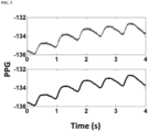
- FIG. 3 is a comparison between a photoplethysmogram signal prior to the filtering process (top panel) and the photoplethysmogram signal subsequent to the filtering process (bottom panel) in some embodiments according to the present disclosure.
- the high frequency noises in the photoplethysmogram signal are removed subsequent to the filtering process.
- the photoplethysmogram signal is smoothed after the treatment by the Savitzky-Golay FIR filter.
- the method in some embodiments further includes obtaining a first electrocardiography R-wave signal of the subject for the purpose of determining a pulse transit time based on the first electrocardiography R-wave signal and the denoised physiological signal.
- the method includes measuring an electrocardiography R-wave of the subject to obtain a second electrocardiography R-wave signal; and filtering a high frequency noise from a second electrocardiography R-wave signal thereby obtaining the first electrocardiography R-wave signal.
- the step of filtering the high frequency noise from the second electrocardiography R-wave signal is performed by mathematical morphology filtering.
- the step of filtering the high frequency noise is performed using a Savitzky-Golay FIR filter, e.g., a third derivative Savitzky-Golay FIR filter.
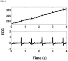
- FIG. 4 is a comparison between an electrocardiography R-wave signal prior to the filtering process (top panel) and the electrocardiography R-wave signal subsequent to the filtering process (bottom panel) in some embodiments according to the present disclosure. Referring to FIG. 4 , the high frequency noises in the electrocardiography R-wave signal are removed subsequent to the filtering process.
- the step of filtering the high frequency noise from the second electrocardiography R-wave signal is performed by the empirical mode decomposition described herein.
- the step of filtering the high frequency noise from the second electrocardiography R-wave signal includes decomposing the second electrocardiography R-wave signal using an empirical mode decomposition algorithm into a sum of a plurality of intrinsic mode functions and a residual; identifying one or more first intrinsic mode functions of the plurality of intrinsic mode functions that are associated with a noise signal (e.g., a high frequency noise), thereby obtaining one or more second intrinsic mode functions of the plurality of intrinsic mode functions that are different from the one or more first intrinsic mode functions; and calculating a denoised electrocardiography R-wave signal (e.g., the first electrocardiography R-wave signal) by accumulating the one or more second intrinsic mode functions.
- a noise signal e.g., a high frequency noise
- the method further includes determining a photoplethysmogram intensity ratio based on the denoised photoplethysmogram signal; and determining a pulse transit time based on the first electrocardiography R-wave signal and the denoised physiological signal.
- the method further includes identifying characteristic points of the denoised photoplethysmogram signal and characteristic points of the first electrocardiography R-wave signal.
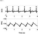
- FIG. 5 is a diagram illustrating characteristic points of the denoised photoplethysmogram signal (PPG) and characteristic points of the first electrocardiography R-wave signal (ECG).
- PPG denoised photoplethysmogram signal
- ECG first electrocardiography R-wave signal
- T denotes an electrocardiography R-wave peak of the first electrocardiography R-wave signal in each cardiac cycle.
- ⁇ de denotes a photoplethysmogram peak of the denoised photoplethysmogram signal in each cardiac cycle
- ⁇ denotes a photoplethysmogram valley of the denoised photoplethysmogram signal in each cardiac cycle
- ⁇ denotes a peak of a first derivative of the denoised photoplethysmogram signal in each cardiac cycle.
- the step of determining the photoplethysmogram intensity ratio includes calculating a ratio of a photoplethysmogram peak intensity to a photoplethysmogram valley intensity in one cardiac cycle.
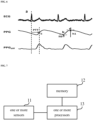
- FIG. 6 illustrates a method of determining a pulse transit time (PTT) and determining a photoplethysmogram intensity ratio.
- h 1 denotes a photoplethysmogram peak intensity of a photoplethysmogram peak d of the denoised photoplethysmogram signal in one cardiac cycle
- h 0 denotes a photoplethysmogram valley intensity of a photoplethysmogram valley b of the denoised photoplethysmogram signal in one cardiac cycle.
- the step of determining the pulse transit time includes determining a time interval between an electrocardiography R-wave peak of the first electrocardiography R-wave signal and a peak of a first derivative of the denoised physiological signal in one cardiac cycle.
- PPG diff is a first derivative of the denoised physiological signal.
- point c in one cardiac cycle of the denoised physiological signal corresponds to a peak of a first derivative of the denoised physiological signal in the same cardiac cycle
- point a of the first electrocardiography R-wave signal corresponds to an electrocardiography R-wave peak in the same cardiac cycle.
- the pulse transit time is determined as the time difference between point a and point c , i.e., the time interval between the electrocardiography R-wave peak of the first electrocardiography R-wave signal and the peak of the first derivative of the denoised physiological signal in a same cardiac cycle.
- the blood pressure of the subject can be determined using a blood pressure calculation algorithm, as discussed above.
- the method includes acquiring an electrocardiography R-wave signal and acquiring an arterial pulse wave signal, e.g., a radial arterial pulse wave signal.
- FIG. 7 is a schematic diagram illustrating the structure of an apparatus for determining a blood pressure of a subject in some embodiments according to the present disclosure.
- the apparatus in some embodiments includes one or more sensors 11, a memory 12, and one or more processors 13.
- the one or more sensors 11 are configured to acquire one or more physiological signals of the subject.
- physiological signals include both electrical signals and non-electrical signals.
- electrical signals include, but are not limited to, an electrocardiogram signal, an electroencephalogram signal, an electromyogram signal, and the like.
- non-electrical biometric signals include, but are not limited to, a blood pressure signal, a pulse wave signal, a body temperature signal, a body motion signal, and the like.
- the one or more physiological signals include at least a pulse wave signal (e.g., a photoplethysmogram signal) of the subject.
- the one or more physiological signals include at least a heart rate signal (e.g., an electrocardiography wave signal) of the subject.
- biosensors include, but are not limited to, a photoelectric sensor, a pressure sensor, an accelerometer, barometer, and an image sensor.
- the apparatus is a wearable apparatus.
- the apparatus is integrated into a smart phone.
- the apparatus is integrated into a tablet computer.
- the apparatus is a stand-alone apparatus.
- the memory 12 stores computer-executable instructions for controlling the one or more processors 13 to determine the blood pressure of the subject using a blood pressure calculation algorithm.
- the blood pressure calculation algorithm is based on a pulse transit time and a photoplethysmogram intensity ratio of the subject.
- the blood pressure of the subject is calculated using Equations (1) and (2) discussed above.
- the memory 12 stores computer-executable instructions for controlling the one or more processors 13 to first decompose a first physiological signal corresponding to a first physiological parameter.
- the first physiological parameter is a pulse wave; and the first physiological signal is a pulse wave signal (e.g., a photoplethysmogram signal).
- the first physiological parameter is a heart rate, and the first physiological signal is an electrocardiography wave signal, e.g., an electrocardiography R-wave signal.
- Various other physiological signals may be denoised using the apparatus described herein.
- the memory 12 stores computer-executable instructions for controlling the one or more processors 13 to first decompose a first physiological signal corresponding to a first physiological parameter using an empirical mode decomposition algorithm into a sum of a plurality of intrinsic mode functions and a residual.
- the first physiological signal may be decomposed into a function according to Equation (3) discussed above.
- each of the plurality of intrinsic mode functions has a characteristic frequency, values of characteristic frequencies of the plurality of intrinsic mode functions are different from each other.
- the memory 12 stores computer-executable instructions for controlling the one or more processors 13 to identify one or more first intrinsic mode functions of the plurality of intrinsic mode functions that are associated with a noise signal, thereby obtaining one or more second intrinsic mode functions of the plurality of intrinsic mode functions that are different from the one or more first intrinsic mode functions.
- the memory 12 stores computer-executable instructions for controlling the one or more processors 13 to select one or more of the plurality of intrinsic mode functions having characteristic frequencies outside a range of acceptable characteristic frequencies as the one or more first intrinsic mode functions.
- the one or more second intrinsic mode functions of the plurality of intrinsic mode functions have characteristic frequencies in the range of acceptable characteristic frequencies.
- the range of acceptable characteristic frequencies is a range of characteristic frequencies corresponding to characteristic frequencies of the first physiological parameter.
- the first physiological parameter is a pulse wave
- the first physiological signal is a pulse wave signal (e.g., a photoplethysmogram signal)
- the range of acceptable characteristic frequencies corresponding to characteristic frequencies of the pulse wave is approximately 0.8 Hz to approximately 1.6 Hz.
- the memory 12 stores computer-executable instructions for controlling the one or more processors 13 to calculate a denoised physiological signal by accumulating the one or more second intrinsic mode functions.
- the denoised physiological signal may be expressed using Equation (4) discussed above.
- the intrinsic mode functions having the lowest characteristic frequencies, IMF n+1 to IMF N , and the residual, r N (t), are not used in computing the denoised physiological signal.
- the denoised physiological signal may be expressed using Equation (5) discussed above.
- the intrinsic mode function having the lowest characteristic frequency, IMF N , and the residual, r N (t) are not used in computing the denoised physiological signal.
- the denoised physiological signal may be expressed using Equation (6) discussed above.
- the first physiological parameter is a pulse wave; and the first physiological signal is a pulse wave signal (e.g., a photoplethysmogram signal).
- the denoised pulse wave signal (e.g., a denoised photoplethysmogram signal) may be expressed using Equation (7) discussed above.
- the intrinsic mode functions having the lowest characteristic frequencies, IMF n+1 to IMF N , and the residual, r N (t), are not used in computing the denoised photoplethysmogram signal.
- the denoised pulse wave signal (e.g., a denoised photoplethysmogram signal) may be expressed using Equation (8) discussed above.
- the intrinsic mode function having the lowest characteristic frequency, IMF N , and the residual, r N (t), are not used in computing the denoised photoplethysmogram signal.
- the denoised pulse wave signal (e.g., a denoised photoplethysmogram signal) may be expressed using Equation (9) discussed above.
- the memory 12 stores computer-executable instructions for controlling the one or more processors 13 to, prior to decompose the first physiological signal, filter a high frequency noise from a second physiological signal thereby obtaining the first physiological signal.
- the one or more sensors 11 are configured to acquire the second physiological signal corresponding to the first physiological parameter.
- the second physiological signal is raw (e.g., unprocessed) data of the first physiological parameter.
- the first physiological parameter is a pulse wave
- the second physiological signal is an unprocessed pulse wave signal (e.g., an unprocessed photoplethysmogram signal)
- the first physiological signal is a pulse wave signal (e.g., a photoplethysmogram signal) in which a high frequency noise is removed.
- filtering the high frequency noise is performed by mathematical morphology filtering.
- filtering the high frequency noise is performed using a Savitzky-Golay FIR filter, e.g., a third derivative Savitzky-Golay FIR filter.
- the memory 12 stores computer-executable instructions for controlling the one or more processors 13 to obtain a first electrocardiography R-wave signal of the subject for the purpose of determining a pulse transit time based on the first electrocardiography R-wave signal and the denoised physiological signal.
- the one or more sensors are configured to acquire an electrocardiography R-wave of the subject to obtain a second electrocardiography R-wave signal; and the memory 12 stores computer-executable instructions for controlling the one or more processors 13 to filter a high frequency noise from a second electrocardiography R-wave signal thereby obtaining the first electrocardiography R-wave signal.
- filtering the high frequency noise is performed by mathematical morphology filtering.
- filtering the high frequency noise is performed using a Savitzky-Golay FIR filter, e.g., a third derivative Savitzky-Golay FIR filter.
- the memory 12 stores computer-executable instructions for controlling the one or more processors 13 to filter the high frequency noise from the second electrocardiography R-wave signal by the empirical mode decomposition algorithm described herein.
- the memory 12 stores computer-executable instructions for controlling the one or more processors 13 to decompose the second electrocardiography R-wave signal using an empirical mode decomposition algorithm into a sum of a plurality of intrinsic mode functions and a residual; identify one or more first intrinsic mode functions of the plurality of intrinsic mode functions that are associated with a noise signal (e.g., a high frequency noise), thereby obtaining one or more second intrinsic mode functions of the plurality of intrinsic mode functions that are different from the one or more first intrinsic mode functions; and calculate a denoised electrocardiography R-wave signal (e.g., the first electrocardiography R-wave signal) by accumulating the one or more second intrinsic mode functions.
- a noise signal e.g., a high frequency noise
- the first physiological parameter is a pulse wave
- the first physiological signal is a photoplethysmogram signal
- the memory 12 stores computer-executable instructions for controlling the one or more processors 13 to determine a photoplethysmogram intensity ratio based on the denoised photoplethysmogram signal; and determine a pulse transit time based on the first electrocardiography R-wave signal and the denoised physiological signal.
- the memory 12 stores computer-executable instructions for controlling the one or more processors 13 to identify characteristic points of the denoised photoplethysmogram signal and characteristic points of the first electrocardiography R-wave signal.
- the memory 12 stores computer-executable instructions for controlling the one or more processors 13 to calculate a ratio of a photoplethysmogram peak intensity to a photoplethysmogram valley intensity in one cardiac cycle, thereby determining the photoplethysmogram intensity ratio.
- the photoplethysmogram intensity ratio is calculated based on Equation (10) discussed above.
- the memory 12 stores computer-executable instructions for controlling the one or more processors 13 to determine a time interval between an electrocardiography R-wave peak of the first electrocardiography R-wave signal and a peak of a first derivative of the denoised physiological signal in one cardiac cycle, thereby determining the pulse transit time.
- the apparatus further includes a data converter such as an analog-to-digital converter for converting the physiological signal measured by the one or more sensors 11 into digital data, and transmitting the digital data to the one or more processors 13 for analysis.
- a data converter such as an analog-to-digital converter for converting the physiological signal measured by the one or more sensors 11 into digital data, and transmitting the digital data to the one or more processors 13 for analysis.
- the apparatus further includes a user interface for displaying information on a display and for the user to input data to the apparatus through an input device.
- the user may input data related to a subject's height, weight, and other physical parameters and genetic traits, and historical physiological parameter data (e.g., historical pulse wave data or historical heart rate data) of the subject.
- the one or more sensors 11 includes one or more electrocardiography sensors configured to acquire an electrocardiography R-wave signal and one or more pulse wave sensors such as a photoplethysmography sensor configured to acquire an arterial pulse wave signal, e.g., a radial arterial pulse wave signal.
- the sensor for measuring electrocardiography R-wave includes a plurality of electrocardiography electrodes.
- all sensors are integrated into the apparatus.
- at least one sensor may be separate from the apparatus's main body and is in remote communication with (e.g., via wireless connection) the processor in the apparatus's main body.
- the main body of the apparatus may be worn on one location of a subject (e.g., the wrist of the subject), and another sensor may be placed on an arterial site away from the main body (e.g., on the subject's leg).
- the apparatus includes a wireless transceiver for receiving or transmitting information from or to a remote site.
- the apparatus may receive real-time database updates through the wireless transceiver.
- the subject is a human.
- the subject is a mammal.
- the subject is a pet (e.g., a dog, a cat).
- Suitable memory may be used in the present apparatus.
- Examples of appropriate computer readable memories include, but are not limited to, magnetic disk or tape, optical storage media such as compact disk (CD) or DVD (digital versatile disk), flash memory, and other non-transitory media.
- the memory is a non-transitory memory.
Landscapes
- Health & Medical Sciences (AREA)
- Life Sciences & Earth Sciences (AREA)
- Engineering & Computer Science (AREA)
- Cardiology (AREA)
- Animal Behavior & Ethology (AREA)
- General Health & Medical Sciences (AREA)
- Biophysics (AREA)
- Biomedical Technology (AREA)
- Heart & Thoracic Surgery (AREA)
- Medical Informatics (AREA)
- Molecular Biology (AREA)
- Surgery (AREA)
- Physics & Mathematics (AREA)
- Pathology (AREA)
- Public Health (AREA)
- Veterinary Medicine (AREA)
- Physiology (AREA)
- Signal Processing (AREA)
- Artificial Intelligence (AREA)
- Computer Vision & Pattern Recognition (AREA)
- Psychiatry (AREA)
- Vascular Medicine (AREA)
- Measuring Pulse, Heart Rate, Blood Pressure Or Blood Flow (AREA)
- Power Engineering (AREA)
Claims (15)
- Vorrichtung zur Bestimmung eines Blutdrucks einer Person, umfassend:einen oder mehrere Sensoren (11), die so konfiguriert sind, dass sie einen ersten physiologischen Parameter der Person messen;einen Speicher (12); undeinen oder mehrere Prozessoren (13);wobei der eine oder die mehreren Sensoren (11) mit dem einen oder den mehreren Prozessoren (13) gekoppelt sind, und der Speicher (12) mit dem einen oder den mehreren Prozessoren (13) gekoppelt ist;der Speicher (12) computerausführbare Anweisungen zum Steuern des einen oder der mehreren Prozessoren (13) speichert zum:Zerlegen eines ersten physiologischen Signals, das dem ersten physiologischen Parameter entspricht, unter Verwendung eines empirischen Modenzerlegungsalgorithmus in eine Summe einer Vielzahl von Intrinsic Mode Functions und einen Rest, wobei der erste physiologische Parameter eine Pulswelle ist; und das erste physiologische Signal ein Photoplethysmogrammsignal ist;Identifizieren einer oder mehrerer erster Intrinsic Mode Functions der Vielzahl von Intrinsic Mode Functions, die einem Rauschsignal zugeordnet sind, wodurch eine oder mehrere zweite Intrinsic Mode Functions der Vielzahl von Intrinsic Mode Functions erhalten werden, die sich von der einen oder den mehreren ersten Intrinsic Mode Functions unterscheiden; undBerechnen eines entrauschten physiologischen Signals durch Akkumulieren der einen oder mehreren zweiten Intrinsic Mode Functions;dadurch gekennzeichnet, dass der Speicher (12) weiter computerausführbare Anweisungen zum Steuern des einen oder der mehreren Prozessoren (13) speichert, zum:Bestimmen eines Photoplethysmogramm-Intensitätsverhältnisses und Bestimmen einer Pulslaufzeit; undBestimmen des Blutdrucks der Person unter Verwendung eines Blutdruckberechnungsalgorithmus auf der Grundlage der Pulslaufzeit und des Photoplethysmogramm-Intensitätsverhältnisses nach den folgenden Gleichungen:

 wobei DBP ein diastolischer Blutdruck der Person ist, SBP ein systolischer Blutdruck der Person ist, PTT die Pulslaufzeit ist, PIR das Photoplethysmogramm-Intensitätsverhältnis ist, m ein Körpergewicht der Person ist, h eine Körpergröße der Person ist, und a, b, c, d und e konstante Koeffizienten sind;wobei das Bestimmen des Photoplethysmogramm-Intensitätsverhältnisses umfasst:Berechnen eines Verhältnisses einer Photoplethysmogramm-Spitzenintensität zu einer Photoplethysmogramm-Talintensität in einem Herzzyklus;Bestimmen des Photoplethysmogramm-Intensitätsverhältnisses auf der Grundlage des Verhältnisses der Photoplethysmogramm-Spitzenintensität zu der Photoplethysmogramm-Talintensität in dem einen Herzzyklus;wobei das Bestimmen der Pulslaufzeit umfasst:Erhalten eines ersten elektrokardiographischen R-Wellen-Signals;Bestimmen eines Zeitintervalls zwischen einer elektrokardiographischen R-Wellen-Spitze des ersten elektrokardiographischen R-Wellen-Signals und einer Spitze einer ersten Ableitung des entrauschten physiologischen Signals in einem Herzzyklus; undBestimmen der Pulslaufzeit auf der Grundlage des Zeitintervalls.
 - Vorrichtung nach Anspruch 1, dadurch gekennzeichnet, dass jede der Vielzahl von Intrinsic Mode Functions eine charakteristische Frequenz aufweist, wobei sich die Werte der charakteristischen Frequenzen der Vielzahl von Intrinsic Mode Functions voneinander unterscheiden.
- Vorrichtung nach Anspruch 2, dadurch gekennzeichnet, dass der Speicher (12) computerausführbare Anweisungen zum Steuern des einen oder der mehreren Prozessoren (13) speichert, um eine oder mehrere von der Vielzahl von Intrinsic Mode Functions mit charakteristischen Frequenzen außerhalb eines Bereichs von akzeptablen charakteristischen Frequenzen als die eine oder die mehreren ersten Intrinsic Mode Functions auszuwählen.
- Vorrichtung nach Anspruch 2, dadurch gekennzeichnet, dass die eine oder mehreren ersten Intrinsic Mode Functions einem niederfrequenten Basisliniendrift zugeordnet sind; und optional die eine oder mehreren ersten Intrinsic Mode Functions einem hochfrequenten Rauschen zugeordnet sind.
- Vorrichtung nach Anspruch 1, dadurch gekennzeichnet, dass der Speicher (12) computerausführbare Anweisungen zum Steuern des einen oder der mehreren Prozessoren (13) speichert, zum:
vor der Zerlegung eines ersten physiologischen Signals, Filtern eines hochfrequenten Rauschens aus einem zweiten physiologischen Signal, um das erste physiologische Signal zu erhalten. - Vorrichtung nach Anspruch 5, dadurch gekennzeichnet, dass das Filtern des hochfrequenten Rauschens unter Verwendung eines Savitzky-Golay FIR-Filters durchgeführt wird.
- Vorrichtung nach Anspruch 1, dadurch gekennzeichnet, dass der eine oder die mehreren Sensoren (11) so konfiguriert sind, dass sie eine elektrokardiographische R-Welle der Person detektieren, um ein zweites elektrokardiographisches R-Wellen-Signal zu erfassen;
der Speicher (12) computerausführbare Anweisungen zum Steuern des einen oder der mehreren Prozessoren (13) speichert, um ein hochfrequentes Rauschen aus dem zweiten elektrokardiographischen R-Wellen-Signal zu filtern und dadurch das erste elektrokardiographische R-Wellen-Signal zu erhalten. - Computerimplementiertes Verfahren zur Bestimmung des Blutdrucks einer Person, umfassend:Zerlegen eines ersten physiologischen Signals, das einem ersten physiologischen Parameter entspricht, unter Verwendung eines empirischen Modenzerlegungsalgorithmus in eine Summe aus einer Vielzahl von Intrinsic Mode Functions und einem Rest, wobei der erste physiologische Parameter eine Pulswelle ist; und das erste physiologische Signal ein Photoplethysmogrammsignal ist;Identifizieren einer oder mehrerer erster Intrinsic Mode Functions der Vielzahl von Intrinsic Mode Functions, die einem Rauschsignal zugeordnet sind, wodurch eine oder mehrere zweite Intrinsic Mode Functions der Vielzahl von Intrinsic Mode Functions erhalten werden, die sich von der einen oder den mehreren ersten Intrinsic Mode Functions unterscheiden; undBerechnen eines entrauschten physiologischen Signals durch Akkumulieren der einen oder mehreren zweiten Intrinsic Mode Functions;dadurch gekennzeichnet, dass das Verfahren weiter umfasst:Bestimmen eines Photoplethysmogramm-Intensitätsverhältnisses und Bestimmen einer Pulslaufzeit; undBestimmen des Blutdrucks der Person unter Verwendung eines Blutdruckberechnungsalgorithmus auf der Grundlage der Pulslaufzeit und des Photoplethysmogramm-Intensitätsverhältnisses nach den folgenden Gleichungen:

 wobei DBP ein diastolischer Blutdruck der Person ist, SBP ein systolischer Blutdruck der Person ist, PTT die Pulslaufzeit ist, PIR das Photoplethysmogramm-Intensitätsverhältnis ist, m ein Körpergewicht der Person ist, h eine Körpergröße der Person ist, und a, b, c, d und e konstante Koeffizienten sind;wobei das Bestimmen des Photoplethysmogramm-Intensitätsverhältnisses umfasst:Berechnen eines Verhältnisses einer Photoplethysmogramm-Spitzenintensität zu einer Photoplethysmogramm-Talintensität in einem Herzzyklus;Bestimmen eines Photoplethysmogramm-Intensitätsverhältnisses auf der Grundlage des Verhältnisses der Photoplethysmogramm-Spitzenintensität zu der Photoplethysmogramm-Talintensität in dem einen Herzzyklus;wobei das Bestimmen der Pulslaufzeit umfasst:Erhalten eines ersten elektrokardiographischen R-Wellen-Signals der Person;Bestimmen eines Zeitintervalls zwischen einer elektrokardiographischen R-Wellen-Spitze des ersten elektrokardiographischen R-Wellen-Signals und einer Spitze einer ersten Ableitung des entrauschten physiologischen Signals in einem Herzzyklus; undBestimmen einer Pulslaufzeit auf der Grundlage des Zeitintervalls.
 - Verfahren nach Anspruch 8, dadurch gekennzeichnet, dass jede der Vielzahl von Intrinsic Mode Functions eine charakteristische Frequenz aufweist, wobei sich die Werte der charakteristischen Frequenzen der Vielzahl von Intrinsic Mode Functions voneinander unterscheiden.
- Verfahren nach Anspruch 9, dadurch gekennzeichnet, dass das Identifizieren der einen oder mehreren ersten Intrinsic Mode Functions das Auswählen einer oder mehrerer von der Vielzahl von Intrinsic Mode Functions mit charakteristischen Frequenzen außerhalb eines Bereichs von akzeptablen charakteristischen Frequenzen als die eine oder mehreren ersten Intrinsic Mode Functions umfasst.
- Verfahren nach Anspruch 10, dadurch gekennzeichnet, dass die eine oder mehreren ersten Intrinsic Mode Functions einem niederfrequenten Basisliniendrift zugeordnet sind.
- Verfahren nach Anspruch 10, dadurch gekennzeichnet, dass die eine oder die mehreren ersten Intrinsic Mode Functions einem hochfrequenten Rauschen zugeordnet sind.
- Verfahren nach Anspruch 8, dadurch gekennzeichnet, dass es vor der Zerlegung des ersten physiologischen Signals weiter umfasst:
Filtern eines hochfrequenten Rauschens aus einem zweiten physiologischen Signal, wodurch das erste physiologische Signal erhalten wird. - Verfahren nach Anspruch 13, dadurch gekennzeichnet, dass das Filtern des hochfrequenten Rauschens unter Verwendung eines Savitzky-Golay FIR-Filters durchgeführt wird.
- Verfahren nach Anspruch 8, dadurch gekennzeichnet, dass das Verfahren weiter umfasst:Messen einer elektrophysiologischen R-Welle der Person, um ein zweites elektrokardiographisches R-Wellen-Signal zu erhalten; undFiltern eines hochfrequenten Rauschens aus einem zweiten elektrokardiographischen R-Wellen-Signal, um dadurch das erste elektrokardiographische R-Wellen-Signal zu erhalten.
Applications Claiming Priority (1)
| Application Number | Priority Date | Filing Date | Title |
|---|---|---|---|
| PCT/CN2017/083055 WO2018201395A1 (en) | 2017-05-04 | 2017-05-04 | Apparatus and method for determining a blood pressure of a subject |
Publications (3)
| Publication Number | Publication Date |
|---|---|
| EP3618700A1 EP3618700A1 (de) | 2020-03-11 |
| EP3618700A4 EP3618700A4 (de) | 2020-12-16 |
| EP3618700B1 true EP3618700B1 (de) | 2024-08-21 |
Family
ID=64016442
Family Applications (1)
| Application Number | Title | Priority Date | Filing Date |
|---|---|---|---|
| EP17866379.5A Active EP3618700B1 (de) | 2017-05-04 | 2017-05-04 | Vorrichtung und verfahren zur bestimmung eines blutdrucks einer person |
Country Status (4)
| Country | Link |
|---|---|
| US (1) | US10925495B2 (de) |
| EP (1) | EP3618700B1 (de) |
| CN (1) | CN109219391A (de) |
| WO (1) | WO2018201395A1 (de) |
Families Citing this family (15)
| Publication number | Priority date | Publication date | Assignee | Title |
|---|---|---|---|---|
| WO2016205414A1 (en) | 2015-06-15 | 2016-12-22 | Vital Labs, Inc. | Method and system for cardiovascular disease assessment and management |
| US10420515B2 (en) | 2015-06-15 | 2019-09-24 | Vital Labs, Inc. | Method and system for acquiring data for assessment of cardiovascular disease |
| EP3566641A1 (de) * | 2018-05-08 | 2019-11-13 | Koninklijke Philips N.V. | Vorrichtung zur bestimmung einer blutdruckmessung |
| EP4037555A4 (de) * | 2019-10-01 | 2023-05-31 | Riva Health, Inc. | Verfahren und system zur bestimmung von kardiovaskulären parametern |
| CN111248881B (zh) * | 2020-02-21 | 2022-08-02 | 乐普(北京)医疗器械股份有限公司 | 一种对血压进行预测的方法和装置 |
| US20240000323A1 (en) * | 2020-10-22 | 2024-01-04 | Korea University Research And Business Foundation | Photoplethysmography-based real-time blood pressure monitoring system using convolutional bidirectional short- and long-term memory recurrent neural network, and real-time blood pressure monitoring method using same |
| US11744523B2 (en) | 2021-03-05 | 2023-09-05 | Riva Health, Inc. | System and method for validating cardiovascular parameter monitors |
| CN113288158B (zh) * | 2021-05-27 | 2022-12-20 | 河北省科学院应用数学研究所 | 基线漂移和高频噪声的去除方法、装置和设备 |
| US11830624B2 (en) | 2021-09-07 | 2023-11-28 | Riva Health, Inc. | System and method for determining data quality for cardiovascular parameter determination |
| CN114027847B (zh) * | 2021-11-17 | 2023-05-05 | 湖南万脉医疗科技有限公司 | 一种基于时频分析的心电信号分析方法 |
| KR102721189B1 (ko) * | 2021-12-20 | 2024-10-24 | 삼성전자주식회사 | 혈압 추정 장치 및 방법 |
| CN115500803B (zh) * | 2022-09-29 | 2025-12-19 | 联想(北京)有限公司 | 一种信息确定方法及电子设备 |
| CN117562560B (zh) * | 2023-11-20 | 2024-07-02 | 北京宜善医学科技有限公司 | 一种康复训练中的运动效果评估方法、装置及存储介质 |
| CN118557162B (zh) * | 2024-07-31 | 2024-10-11 | 深圳市龙田医疗科技有限公司 | 一种血压计校准方法和系统 |
| CN121694716B (zh) * | 2026-02-12 | 2026-05-08 | 北京汉王大健康科技有限公司 | 基于上臂式血压计的脉搏波传导速度测量方法、装置 |
Family Cites Families (14)
| Publication number | Priority date | Publication date | Assignee | Title |
|---|---|---|---|---|
| US6381559B1 (en) | 1996-08-12 | 2002-04-30 | The United States Of America As Represented By The Administrator Of The National Aeronautics And Space Administration | Empirical mode decomposition apparatus, method and article of manufacture for analyzing biological signals and performing curve fitting |
| US8594773B2 (en) * | 2007-04-25 | 2013-11-26 | Siemens Medical Solutions Usa, Inc. | Denoising and artifact rejection for cardiac signal in a sensis system |
| US8211022B2 (en) | 2008-11-18 | 2012-07-03 | DynaDx Corporation | Systems and methods for assessing dynamic cerebral autoregulation |
| CN102018503B (zh) | 2010-10-21 | 2012-12-12 | 中国科学院深圳先进技术研究院 | 生命探测雷达中的呼吸与心跳信号的提取方法及装置 |
| CA2776204C (en) | 2011-05-02 | 2015-02-24 | The University Of Ottawa | Apparatus and method for electrocardiogram-assisted blood pressure measurement |
| CN102488503B (zh) * | 2011-12-14 | 2014-02-19 | 中国航天员科研训练中心 | 连续血压测量装置 |
| CN105796079A (zh) * | 2014-12-28 | 2016-07-27 | 天津心康科技发展有限公司 | 一种无创连续血压检测方法 |
| JP6600154B2 (ja) | 2015-04-28 | 2019-10-30 | フクダ電子株式会社 | 生体信号処理装置およびその制御方法 |
| US20170079591A1 (en) * | 2015-09-21 | 2017-03-23 | Qualcomm Incorporated | System and method for obtaining vital measurements using a mobile device |
| CA3001628A1 (en) * | 2015-10-13 | 2017-04-20 | Salu Design Group Inc. | Wearable health monitors and methods of monitoring health |
| CN106073729B (zh) * | 2016-05-31 | 2019-08-27 | 中国科学院苏州生物医学工程技术研究所 | 光电容积脉搏波信号的采集方法 |
| WO2018025257A1 (en) * | 2016-08-02 | 2018-02-08 | ChroniSense Medical Ltd. | Blood pressure measurement using a wearable device |
| CN106343976B (zh) | 2016-09-14 | 2018-09-07 | 京东方科技集团股份有限公司 | 建立血压模型的方法和装置以及确定血压的方法和装置 |
| KR102655671B1 (ko) * | 2016-10-12 | 2024-04-05 | 삼성전자주식회사 | 생체정보 추정 장치 및 방법 |
-
2017
- 2017-05-04 CN CN201780000292.0A patent/CN109219391A/zh active Pending
- 2017-05-04 EP EP17866379.5A patent/EP3618700B1/de active Active
- 2017-05-04 US US15/766,987 patent/US10925495B2/en active Active
- 2017-05-04 WO PCT/CN2017/083055 patent/WO2018201395A1/en not_active Ceased
Also Published As
| Publication number | Publication date |
|---|---|
| CN109219391A (zh) | 2019-01-15 |
| EP3618700A4 (de) | 2020-12-16 |
| US10925495B2 (en) | 2021-02-23 |
| EP3618700A1 (de) | 2020-03-11 |
| WO2018201395A1 (en) | 2018-11-08 |
| US20190059753A1 (en) | 2019-02-28 |
Similar Documents
| Publication | Publication Date | Title |
|---|---|---|
| US10925495B2 (en) | Apparatus and method for determining a blood pressure of a subject | |
| US20220296176A1 (en) | Processing biological data | |
| US11172891B2 (en) | Method and apparatus for deriving mean arterial pressure of a subject | |
| EP4154805B1 (de) | Vorrichtung zur überwachung der herzfrequenz und atmung | |
| US20120029320A1 (en) | Systems and methods for processing multiple physiological signals | |
| EP3061391B1 (de) | Vorrichtung und Verfahren zur Bestimmung des Blutdrucks | |
| US20150018702A1 (en) | Devices and Methods for Real-Time Denoising of Electrocardiograms | |
| CN115251866A (zh) | 一种采用毫米波雷达的连续血压检测方法、检测系统及可穿戴装置 | |
| US20180085069A1 (en) | Method and Device for Processing Bio-Signals | |
| Medina et al. | Continuous blood pressure estimation in wearable devices using photoplethysmography: A review | |
| Szmajda et al. | Three methods for determining respiratory waves from ECG (Part I) | |
| JP2024529373A (ja) | 被験者の心血管系に関連する健康情報を決定するための装置、システムおよび方法 | |
| Hadjem et al. | Early detection of Myocardial Infarction using WBAN | |
| Mujumdar et al. | Principal Component Analysis (PCA) based single-channel, non-invasive fetal ECG extraction | |
| JP6750030B2 (ja) | 被検者の収縮期血圧および/または拡張期血圧を導出する方法 | |
| US12178585B2 (en) | Multi sensor and method | |
| US20250380879A1 (en) | System and method for sensors integration for non-static continuous blood pressure monitoring | |
| Semiz | A Compact Multimodal Patch for Continuous and Electrode-Free Cardiopulmonary Monitoring | |
| De Alwis et al. | Parametric Model between Pulse Transit Time and Systolic and Diastolic Blood Pressures for Non-Invasive Blood Pressure Estimation | |
| CN112990029B (zh) | 一种评估静脉血管状态的装置 | |
| Escalona et al. | Feasibility of Wearable Armband Bipolar ECG Lead-1 for Long-term HRV Monitoring by Combined Signal Averaging and 2-stage Wavelet Denoising | |
| CN120203544A (zh) | 血压预测方法、装置及电子设备 | |
| Sangeetha et al. | A Continuous Smart Abdominal Fetal Heart Rate Monitor using Photoplethysmography | |
| CN121359882A (zh) | 血压监测模型的训练方法、监测方法、电子设备及装置 | |
| Kew et al. | Implementation and Estimation of Wearable ECG Monitoring System for Ubiquitous Healthcare |
Legal Events
| Date | Code | Title | Description |
|---|---|---|---|
| STAA | Information on the status of an ep patent application or granted ep patent |
Free format text: STATUS: UNKNOWN |
|
| STAA | Information on the status of an ep patent application or granted ep patent |
Free format text: STATUS: THE INTERNATIONAL PUBLICATION HAS BEEN MADE |
|
| PUAI | Public reference made under article 153(3) epc to a published international application that has entered the european phase |
Free format text: ORIGINAL CODE: 0009012 |
|
| STAA | Information on the status of an ep patent application or granted ep patent |
Free format text: STATUS: REQUEST FOR EXAMINATION WAS MADE |
|
| 17P | Request for examination filed |
Effective date: 20180509 |
|
| AK | Designated contracting states |
Kind code of ref document: A1 Designated state(s): AL AT BE BG CH CY CZ DE DK EE ES FI FR GB GR HR HU IE IS IT LI LT LU LV MC MK MT NL NO PL PT RO RS SE SI SK SM TR |
|
| AX | Request for extension of the european patent |
Extension state: BA ME |
|
| DAV | Request for validation of the european patent (deleted) | ||
| DAX | Request for extension of the european patent (deleted) | ||
| A4 | Supplementary search report drawn up and despatched |
Effective date: 20201113 |
|
| RIC1 | Information provided on ipc code assigned before grant |
Ipc: A61B 5/021 20060101AFI20201109BHEP Ipc: A61B 5/00 20060101ALN20201109BHEP Ipc: A61B 5/0456 20060101ALI20201109BHEP Ipc: A61B 5/024 20060101ALI20201109BHEP Ipc: A61B 5/0245 20060101ALI20201109BHEP |
|
| GRAP | Despatch of communication of intention to grant a patent |
Free format text: ORIGINAL CODE: EPIDOSNIGR1 |
|
| STAA | Information on the status of an ep patent application or granted ep patent |
Free format text: STATUS: GRANT OF PATENT IS INTENDED |
|
| RIC1 | Information provided on ipc code assigned before grant |
Ipc: A61B 5/021 20060101AFI20240307BHEP |
|
| INTG | Intention to grant announced |
Effective date: 20240328 |
|
| GRAS | Grant fee paid |
Free format text: ORIGINAL CODE: EPIDOSNIGR3 |
|
| GRAA | (expected) grant |
Free format text: ORIGINAL CODE: 0009210 |
|
| STAA | Information on the status of an ep patent application or granted ep patent |
Free format text: STATUS: THE PATENT HAS BEEN GRANTED |
|
| AK | Designated contracting states |
Kind code of ref document: B1 Designated state(s): AL AT BE BG CH CY CZ DE DK EE ES FI FR GB GR HR HU IE IS IT LI LT LU LV MC MK MT NL NO PL PT RO RS SE SI SK SM TR |
|
| REG | Reference to a national code |
Ref country code: GB Ref legal event code: FG4D |
|
| REG | Reference to a national code |
Ref country code: CH Ref legal event code: EP |
|
| REG | Reference to a national code |
Ref country code: IE Ref legal event code: FG4D |
|
| REG | Reference to a national code |
Ref country code: DE Ref legal event code: R096 Ref document number: 602017084322 Country of ref document: DE |
|
| REG | Reference to a national code |
Ref country code: LT Ref legal event code: MG9D |
|
| REG | Reference to a national code |
Ref country code: NL Ref legal event code: MP Effective date: 20240821 |
|
| PG25 | Lapsed in a contracting state [announced via postgrant information from national office to epo] |
Ref country code: NO Free format text: LAPSE BECAUSE OF FAILURE TO SUBMIT A TRANSLATION OF THE DESCRIPTION OR TO PAY THE FEE WITHIN THE PRESCRIBED TIME-LIMIT Effective date: 20241121 |
|
| REG | Reference to a national code |
Ref country code: AT Ref legal event code: MK05 Ref document number: 1714683 Country of ref document: AT Kind code of ref document: T Effective date: 20240821 |
|
| PG25 | Lapsed in a contracting state [announced via postgrant information from national office to epo] |
Ref country code: NL Free format text: LAPSE BECAUSE OF FAILURE TO SUBMIT A TRANSLATION OF THE DESCRIPTION OR TO PAY THE FEE WITHIN THE PRESCRIBED TIME-LIMIT Effective date: 20240821 Ref country code: PL Free format text: LAPSE BECAUSE OF FAILURE TO SUBMIT A TRANSLATION OF THE DESCRIPTION OR TO PAY THE FEE WITHIN THE PRESCRIBED TIME-LIMIT Effective date: 20240821 Ref country code: GR Free format text: LAPSE BECAUSE OF FAILURE TO SUBMIT A TRANSLATION OF THE DESCRIPTION OR TO PAY THE FEE WITHIN THE PRESCRIBED TIME-LIMIT Effective date: 20241122 Ref country code: PT Free format text: LAPSE BECAUSE OF FAILURE TO SUBMIT A TRANSLATION OF THE DESCRIPTION OR TO PAY THE FEE WITHIN THE PRESCRIBED TIME-LIMIT Effective date: 20241223 Ref country code: FI Free format text: LAPSE BECAUSE OF FAILURE TO SUBMIT A TRANSLATION OF THE DESCRIPTION OR TO PAY THE FEE WITHIN THE PRESCRIBED TIME-LIMIT Effective date: 20240821 |
|
| PG25 | Lapsed in a contracting state [announced via postgrant information from national office to epo] |
Ref country code: BG Free format text: LAPSE BECAUSE OF FAILURE TO SUBMIT A TRANSLATION OF THE DESCRIPTION OR TO PAY THE FEE WITHIN THE PRESCRIBED TIME-LIMIT Effective date: 20240821 |
|
| PG25 | Lapsed in a contracting state [announced via postgrant information from national office to epo] |
Ref country code: LV Free format text: LAPSE BECAUSE OF FAILURE TO SUBMIT A TRANSLATION OF THE DESCRIPTION OR TO PAY THE FEE WITHIN THE PRESCRIBED TIME-LIMIT Effective date: 20240821 |
|
| PG25 | Lapsed in a contracting state [announced via postgrant information from national office to epo] |
Ref country code: IS Free format text: LAPSE BECAUSE OF FAILURE TO SUBMIT A TRANSLATION OF THE DESCRIPTION OR TO PAY THE FEE WITHIN THE PRESCRIBED TIME-LIMIT Effective date: 20241221 Ref country code: AT Free format text: LAPSE BECAUSE OF FAILURE TO SUBMIT A TRANSLATION OF THE DESCRIPTION OR TO PAY THE FEE WITHIN THE PRESCRIBED TIME-LIMIT Effective date: 20240821 |
|
| PG25 | Lapsed in a contracting state [announced via postgrant information from national office to epo] |
Ref country code: HR Free format text: LAPSE BECAUSE OF FAILURE TO SUBMIT A TRANSLATION OF THE DESCRIPTION OR TO PAY THE FEE WITHIN THE PRESCRIBED TIME-LIMIT Effective date: 20240821 |
|
| PG25 | Lapsed in a contracting state [announced via postgrant information from national office to epo] |
Ref country code: RS Free format text: LAPSE BECAUSE OF FAILURE TO SUBMIT A TRANSLATION OF THE DESCRIPTION OR TO PAY THE FEE WITHIN THE PRESCRIBED TIME-LIMIT Effective date: 20241121 Ref country code: ES Free format text: LAPSE BECAUSE OF FAILURE TO SUBMIT A TRANSLATION OF THE DESCRIPTION OR TO PAY THE FEE WITHIN THE PRESCRIBED TIME-LIMIT Effective date: 20240821 |
|
| PG25 | Lapsed in a contracting state [announced via postgrant information from national office to epo] |
Ref country code: RS Free format text: LAPSE BECAUSE OF FAILURE TO SUBMIT A TRANSLATION OF THE DESCRIPTION OR TO PAY THE FEE WITHIN THE PRESCRIBED TIME-LIMIT Effective date: 20241121 Ref country code: PT Free format text: LAPSE BECAUSE OF FAILURE TO SUBMIT A TRANSLATION OF THE DESCRIPTION OR TO PAY THE FEE WITHIN THE PRESCRIBED TIME-LIMIT Effective date: 20241223 Ref country code: PL Free format text: LAPSE BECAUSE OF FAILURE TO SUBMIT A TRANSLATION OF THE DESCRIPTION OR TO PAY THE FEE WITHIN THE PRESCRIBED TIME-LIMIT Effective date: 20240821 Ref country code: NO Free format text: LAPSE BECAUSE OF FAILURE TO SUBMIT A TRANSLATION OF THE DESCRIPTION OR TO PAY THE FEE WITHIN THE PRESCRIBED TIME-LIMIT Effective date: 20241121 Ref country code: NL Free format text: LAPSE BECAUSE OF FAILURE TO SUBMIT A TRANSLATION OF THE DESCRIPTION OR TO PAY THE FEE WITHIN THE PRESCRIBED TIME-LIMIT Effective date: 20240821 Ref country code: LV Free format text: LAPSE BECAUSE OF FAILURE TO SUBMIT A TRANSLATION OF THE DESCRIPTION OR TO PAY THE FEE WITHIN THE PRESCRIBED TIME-LIMIT Effective date: 20240821 Ref country code: IS Free format text: LAPSE BECAUSE OF FAILURE TO SUBMIT A TRANSLATION OF THE DESCRIPTION OR TO PAY THE FEE WITHIN THE PRESCRIBED TIME-LIMIT Effective date: 20241221 Ref country code: HR Free format text: LAPSE BECAUSE OF FAILURE TO SUBMIT A TRANSLATION OF THE DESCRIPTION OR TO PAY THE FEE WITHIN THE PRESCRIBED TIME-LIMIT Effective date: 20240821 Ref country code: GR Free format text: LAPSE BECAUSE OF FAILURE TO SUBMIT A TRANSLATION OF THE DESCRIPTION OR TO PAY THE FEE WITHIN THE PRESCRIBED TIME-LIMIT Effective date: 20241122 Ref country code: FI Free format text: LAPSE BECAUSE OF FAILURE TO SUBMIT A TRANSLATION OF THE DESCRIPTION OR TO PAY THE FEE WITHIN THE PRESCRIBED TIME-LIMIT Effective date: 20240821 Ref country code: ES Free format text: LAPSE BECAUSE OF FAILURE TO SUBMIT A TRANSLATION OF THE DESCRIPTION OR TO PAY THE FEE WITHIN THE PRESCRIBED TIME-LIMIT Effective date: 20240821 Ref country code: BG Free format text: LAPSE BECAUSE OF FAILURE TO SUBMIT A TRANSLATION OF THE DESCRIPTION OR TO PAY THE FEE WITHIN THE PRESCRIBED TIME-LIMIT Effective date: 20240821 Ref country code: AT Free format text: LAPSE BECAUSE OF FAILURE TO SUBMIT A TRANSLATION OF THE DESCRIPTION OR TO PAY THE FEE WITHIN THE PRESCRIBED TIME-LIMIT Effective date: 20240821 |
|
| PG25 | Lapsed in a contracting state [announced via postgrant information from national office to epo] |
Ref country code: SM Free format text: LAPSE BECAUSE OF FAILURE TO SUBMIT A TRANSLATION OF THE DESCRIPTION OR TO PAY THE FEE WITHIN THE PRESCRIBED TIME-LIMIT Effective date: 20240821 Ref country code: RO Free format text: LAPSE BECAUSE OF FAILURE TO SUBMIT A TRANSLATION OF THE DESCRIPTION OR TO PAY THE FEE WITHIN THE PRESCRIBED TIME-LIMIT Effective date: 20240821 Ref country code: DK Free format text: LAPSE BECAUSE OF FAILURE TO SUBMIT A TRANSLATION OF THE DESCRIPTION OR TO PAY THE FEE WITHIN THE PRESCRIBED TIME-LIMIT Effective date: 20240821 |
|
| PG25 | Lapsed in a contracting state [announced via postgrant information from national office to epo] |
Ref country code: EE Free format text: LAPSE BECAUSE OF FAILURE TO SUBMIT A TRANSLATION OF THE DESCRIPTION OR TO PAY THE FEE WITHIN THE PRESCRIBED TIME-LIMIT Effective date: 20240821 |
|
| PG25 | Lapsed in a contracting state [announced via postgrant information from national office to epo] |
Ref country code: CZ Free format text: LAPSE BECAUSE OF FAILURE TO SUBMIT A TRANSLATION OF THE DESCRIPTION OR TO PAY THE FEE WITHIN THE PRESCRIBED TIME-LIMIT Effective date: 20240821 |
|
| PG25 | Lapsed in a contracting state [announced via postgrant information from national office to epo] |
Ref country code: SK Free format text: LAPSE BECAUSE OF FAILURE TO SUBMIT A TRANSLATION OF THE DESCRIPTION OR TO PAY THE FEE WITHIN THE PRESCRIBED TIME-LIMIT Effective date: 20240821 Ref country code: IT Free format text: LAPSE BECAUSE OF FAILURE TO SUBMIT A TRANSLATION OF THE DESCRIPTION OR TO PAY THE FEE WITHIN THE PRESCRIBED TIME-LIMIT Effective date: 20240821 |
|
| REG | Reference to a national code |
Ref country code: DE Ref legal event code: R097 Ref document number: 602017084322 Country of ref document: DE |
|
| PLBE | No opposition filed within time limit |
Free format text: ORIGINAL CODE: 0009261 |
|
| STAA | Information on the status of an ep patent application or granted ep patent |
Free format text: STATUS: NO OPPOSITION FILED WITHIN TIME LIMIT |
|
| PGFP | Annual fee paid to national office [announced via postgrant information from national office to epo] |
Ref country code: DE Payment date: 20250519 Year of fee payment: 9 |
|
| 26N | No opposition filed |
Effective date: 20250522 |
|
| PG25 | Lapsed in a contracting state [announced via postgrant information from national office to epo] |
Ref country code: SE Free format text: LAPSE BECAUSE OF FAILURE TO SUBMIT A TRANSLATION OF THE DESCRIPTION OR TO PAY THE FEE WITHIN THE PRESCRIBED TIME-LIMIT Effective date: 20240821 |
|
| REG | Reference to a national code |
Ref country code: CH Ref legal event code: H13 Free format text: ST27 STATUS EVENT CODE: U-0-0-H10-H13 (AS PROVIDED BY THE NATIONAL OFFICE) Effective date: 20251223 |
|
| PG25 | Lapsed in a contracting state [announced via postgrant information from national office to epo] |
Ref country code: LU Free format text: LAPSE BECAUSE OF NON-PAYMENT OF DUE FEES Effective date: 20250504 |
|
| PG25 | Lapsed in a contracting state [announced via postgrant information from national office to epo] |
Ref country code: CH Free format text: LAPSE BECAUSE OF NON-PAYMENT OF DUE FEES Effective date: 20250531 |
|
| REG | Reference to a national code |
Ref country code: BE Ref legal event code: MM Effective date: 20250531 |
|
| PG25 | Lapsed in a contracting state [announced via postgrant information from national office to epo] |
Ref country code: MC Free format text: LAPSE BECAUSE OF FAILURE TO SUBMIT A TRANSLATION OF THE DESCRIPTION OR TO PAY THE FEE WITHIN THE PRESCRIBED TIME-LIMIT Effective date: 20240821 |
|
| PGFP | Annual fee paid to national office [announced via postgrant information from national office to epo] |
Ref country code: GB Payment date: 20260323 Year of fee payment: 10 |
|
| PG25 | Lapsed in a contracting state [announced via postgrant information from national office to epo] |
Ref country code: IE Free format text: LAPSE BECAUSE OF NON-PAYMENT OF DUE FEES Effective date: 20250504 |
|
| PG25 | Lapsed in a contracting state [announced via postgrant information from national office to epo] |
Ref country code: BE Free format text: LAPSE BECAUSE OF NON-PAYMENT OF DUE FEES Effective date: 20250531 |
|
| PG25 | Lapsed in a contracting state [announced via postgrant information from national office to epo] |
Ref country code: FR Free format text: LAPSE BECAUSE OF NON-PAYMENT OF DUE FEES Effective date: 20250531 |