EP3619023B1 - Commande et réglage de la pression d'une machine de moulage par injection à fonctionnement cyclique - Google Patents
Commande et réglage de la pression d'une machine de moulage par injection à fonctionnement cyclique Download PDFInfo
- Publication number
- EP3619023B1 EP3619023B1 EP18721795.5A EP18721795A EP3619023B1 EP 3619023 B1 EP3619023 B1 EP 3619023B1 EP 18721795 A EP18721795 A EP 18721795A EP 3619023 B1 EP3619023 B1 EP 3619023B1
- Authority
- EP
- European Patent Office
- Prior art keywords
- pressure
- target
- actual
- holding
- function
- Prior art date
- Legal status (The legal status is an assumption and is not a legal conclusion. Google has not performed a legal analysis and makes no representation as to the accuracy of the status listed.)
- Active
Links
Images


Classifications
-
- B—PERFORMING OPERATIONS; TRANSPORTING
- B29—WORKING OF PLASTICS; WORKING OF SUBSTANCES IN A PLASTIC STATE IN GENERAL
- B29C—SHAPING OR JOINING OF PLASTICS; SHAPING OF MATERIAL IN A PLASTIC STATE, NOT OTHERWISE PROVIDED FOR; AFTER-TREATMENT OF THE SHAPED PRODUCTS, e.g. REPAIRING
- B29C45/00—Injection moulding, i.e. forcing the required volume of moulding material through a nozzle into a closed mould; Apparatus therefor
- B29C45/17—Component parts, details or accessories; Auxiliary operations
- B29C45/76—Measuring, controlling or regulating
- B29C45/77—Measuring, controlling or regulating of velocity or pressure of moulding material
-
- B—PERFORMING OPERATIONS; TRANSPORTING
- B29—WORKING OF PLASTICS; WORKING OF SUBSTANCES IN A PLASTIC STATE IN GENERAL
- B29C—SHAPING OR JOINING OF PLASTICS; SHAPING OF MATERIAL IN A PLASTIC STATE, NOT OTHERWISE PROVIDED FOR; AFTER-TREATMENT OF THE SHAPED PRODUCTS, e.g. REPAIRING
- B29C45/00—Injection moulding, i.e. forcing the required volume of moulding material through a nozzle into a closed mould; Apparatus therefor
- B29C45/17—Component parts, details or accessories; Auxiliary operations
- B29C45/76—Measuring, controlling or regulating
- B29C45/766—Measuring, controlling or regulating the setting or resetting of moulding conditions, e.g. before starting a cycle
-
- B—PERFORMING OPERATIONS; TRANSPORTING
- B29—WORKING OF PLASTICS; WORKING OF SUBSTANCES IN A PLASTIC STATE IN GENERAL
- B29C—SHAPING OR JOINING OF PLASTICS; SHAPING OF MATERIAL IN A PLASTIC STATE, NOT OTHERWISE PROVIDED FOR; AFTER-TREATMENT OF THE SHAPED PRODUCTS, e.g. REPAIRING
- B29C2945/00—Indexing scheme relating to injection moulding, i.e. forcing the required volume of moulding material through a nozzle into a closed mould
- B29C2945/76—Measuring, controlling or regulating
- B29C2945/76003—Measured parameter
- B29C2945/76006—Pressure
- B29C2945/7601—Pressure derivative, change thereof
-
- B—PERFORMING OPERATIONS; TRANSPORTING
- B29—WORKING OF PLASTICS; WORKING OF SUBSTANCES IN A PLASTIC STATE IN GENERAL
- B29C—SHAPING OR JOINING OF PLASTICS; SHAPING OF MATERIAL IN A PLASTIC STATE, NOT OTHERWISE PROVIDED FOR; AFTER-TREATMENT OF THE SHAPED PRODUCTS, e.g. REPAIRING
- B29C2945/00—Indexing scheme relating to injection moulding, i.e. forcing the required volume of moulding material through a nozzle into a closed mould
- B29C2945/76—Measuring, controlling or regulating
- B29C2945/76177—Location of measurement
- B29C2945/76254—Mould
- B29C2945/76257—Mould cavity
-
- B—PERFORMING OPERATIONS; TRANSPORTING
- B29—WORKING OF PLASTICS; WORKING OF SUBSTANCES IN A PLASTIC STATE IN GENERAL
- B29C—SHAPING OR JOINING OF PLASTICS; SHAPING OF MATERIAL IN A PLASTIC STATE, NOT OTHERWISE PROVIDED FOR; AFTER-TREATMENT OF THE SHAPED PRODUCTS, e.g. REPAIRING
- B29C2945/00—Indexing scheme relating to injection moulding, i.e. forcing the required volume of moulding material through a nozzle into a closed mould
- B29C2945/76—Measuring, controlling or regulating
- B29C2945/76177—Location of measurement
- B29C2945/76287—Moulding material
-
- B—PERFORMING OPERATIONS; TRANSPORTING
- B29—WORKING OF PLASTICS; WORKING OF SUBSTANCES IN A PLASTIC STATE IN GENERAL
- B29C—SHAPING OR JOINING OF PLASTICS; SHAPING OF MATERIAL IN A PLASTIC STATE, NOT OTHERWISE PROVIDED FOR; AFTER-TREATMENT OF THE SHAPED PRODUCTS, e.g. REPAIRING
- B29C2945/00—Indexing scheme relating to injection moulding, i.e. forcing the required volume of moulding material through a nozzle into a closed mould
- B29C2945/76—Measuring, controlling or regulating
- B29C2945/76344—Phase or stage of measurement
- B29C2945/76384—Holding, dwelling
-
- B—PERFORMING OPERATIONS; TRANSPORTING
- B29—WORKING OF PLASTICS; WORKING OF SUBSTANCES IN A PLASTIC STATE IN GENERAL
- B29C—SHAPING OR JOINING OF PLASTICS; SHAPING OF MATERIAL IN A PLASTIC STATE, NOT OTHERWISE PROVIDED FOR; AFTER-TREATMENT OF THE SHAPED PRODUCTS, e.g. REPAIRING
- B29C2945/00—Indexing scheme relating to injection moulding, i.e. forcing the required volume of moulding material through a nozzle into a closed mould
- B29C2945/76—Measuring, controlling or regulating
- B29C2945/76494—Controlled parameter
- B29C2945/76498—Pressure
-
- B—PERFORMING OPERATIONS; TRANSPORTING
- B29—WORKING OF PLASTICS; WORKING OF SUBSTANCES IN A PLASTIC STATE IN GENERAL
- B29C—SHAPING OR JOINING OF PLASTICS; SHAPING OF MATERIAL IN A PLASTIC STATE, NOT OTHERWISE PROVIDED FOR; AFTER-TREATMENT OF THE SHAPED PRODUCTS, e.g. REPAIRING
- B29C2945/00—Indexing scheme relating to injection moulding, i.e. forcing the required volume of moulding material through a nozzle into a closed mould
- B29C2945/76—Measuring, controlling or regulating
- B29C2945/76655—Location of control
- B29C2945/76732—Mould
- B29C2945/76735—Mould cavity
-
- B—PERFORMING OPERATIONS; TRANSPORTING
- B29—WORKING OF PLASTICS; WORKING OF SUBSTANCES IN A PLASTIC STATE IN GENERAL
- B29C—SHAPING OR JOINING OF PLASTICS; SHAPING OF MATERIAL IN A PLASTIC STATE, NOT OTHERWISE PROVIDED FOR; AFTER-TREATMENT OF THE SHAPED PRODUCTS, e.g. REPAIRING
- B29C2945/00—Indexing scheme relating to injection moulding, i.e. forcing the required volume of moulding material through a nozzle into a closed mould
- B29C2945/76—Measuring, controlling or regulating
- B29C2945/76655—Location of control
- B29C2945/76765—Moulding material
-
- B—PERFORMING OPERATIONS; TRANSPORTING
- B29—WORKING OF PLASTICS; WORKING OF SUBSTANCES IN A PLASTIC STATE IN GENERAL
- B29C—SHAPING OR JOINING OF PLASTICS; SHAPING OF MATERIAL IN A PLASTIC STATE, NOT OTHERWISE PROVIDED FOR; AFTER-TREATMENT OF THE SHAPED PRODUCTS, e.g. REPAIRING
- B29C2945/00—Indexing scheme relating to injection moulding, i.e. forcing the required volume of moulding material through a nozzle into a closed mould
- B29C2945/76—Measuring, controlling or regulating
- B29C2945/76822—Phase or stage of control
- B29C2945/76862—Holding, dwelling
-
- B—PERFORMING OPERATIONS; TRANSPORTING
- B29—WORKING OF PLASTICS; WORKING OF SUBSTANCES IN A PLASTIC STATE IN GENERAL
- B29C—SHAPING OR JOINING OF PLASTICS; SHAPING OF MATERIAL IN A PLASTIC STATE, NOT OTHERWISE PROVIDED FOR; AFTER-TREATMENT OF THE SHAPED PRODUCTS, e.g. REPAIRING
- B29C2945/00—Indexing scheme relating to injection moulding, i.e. forcing the required volume of moulding material through a nozzle into a closed mould
- B29C2945/76—Measuring, controlling or regulating
- B29C2945/76929—Controlling method
- B29C2945/76933—The operating conditions are corrected immediately, during the same phase or cycle
Definitions
- setpoint injection pressure As a constant during the holding pressure control phase. This can take place in the form of a setpoint jump, which takes place at a switchover point in time at which the injection molding machine enters the holding pressure control phase is switched. Due to the setpoint jump, a transition process takes place during which the actual injection pressure is adjusted to the predetermined constant setpoint injection pressure with the aid of the control means.
- a single process (intermediate process) is provided between an injection process and a packaging process in an injection molding cycle.
- conditions for switching from the injection process to the intermediate process and for switching from the intermediate process to the packaging process are individually set.
- an injection pressure is detected and a target pressure is obtained based on the injection pressure.
- Pressure control is performed in the intermediate process based on the set target pressure. Only then does it switch to the packaging process.
- a changeover to a holding pressure control phase takes place at a changeover time.
- the switching point in time can depend on different parameters and can at least approximately coincide with a point in time at which the at least one cavity is completely or at least almost completely filled with the injection molding material.
- a target pressure in particular a target injection pressure, is specified for the holding pressure control phase.
- the pressure in particular an injection pressure, can be influenced or adjusted to this by means of a suitable control device.
- the actual pressure in particular the actual injection pressure
- the actual pressure usually has a value that deviates from a pressure level desired during the post-pressure control phase. It is possible to initially adapt the setpoint pressure, in particular the setpoint injection pressure, to the current actual pressure, in particular the actual injection pressure, at the switchover time. From this actual value prevailing at the switchover time, the actual pressure, in particular the actual injection pressure, is set to a different pressure, in particular a constant pressure, during a transition process by a control and/or regulating process.
- a control-technical transition process which can also be referred to as a compensation process, can be understood here as a behavior during a period of time from the switchover time to a later further point in time, at which the actual injection pressure falls to a desired extent to a changed value of the setpoint Injection pressure is set by means of control means, in particular up to a predetermined or specifiable deviation from a constant pressure level of the readjustment phase.
- the setpoint injection pressure profile has, in particular, a large number of different gradients, in particular increasing or decreasing.
- a first derivation of the desired injection pressure profile preferably decreases in terms of absolute value, in particular decreases in terms of absolute value towards zero towards the end of the transition process.
- the setpoint injection pressure curve can therefore be optionally continuously differentiated for the smooth transition and not differentiated for the abrupt transition at the switchover time.
- an undesired transient process when the holding pressure level is reached can be avoided or at least significantly reduced by the curvature compared to a step or linear ramp.
- an otherwise customary linear ramp or step can be achieved for the target injection pressure curve by means of quadratic damping.
- a conventional controller can advantageously be used.
- a desired behavior of the injection molding machine during the transition process can therefore be achieved simply by the curvature of the target injection pressure profile in combination with the controller that is present.
- the initial gradient can be specified manually or automatically as a function of at least one parameter, measured variable and/or process variable occurring on the injection molding machine.
- An abrupt transition to the holding pressure control phase is preferably generated by means of the target injection pressure curve.
- An abrupt transition to the holding-pressure control phase can be understood to mean that the holding-pressure level of the holding-pressure control phase is adjusted as quickly as possible, starting from a current value of the actual injection pressure at the switching time.
- a first derivation of the target injection pressure curve shortly after the switchover time can be selected to be much larger or much smaller than a first derivation of the actual injection pressure curve shortly before the switchover time.
- the absolute value of the first derivative of the target injection pressure profile can decrease to zero and/or the second derivative of the target injection pressure profile can also decrease in absolute value to zero. Due to the additional course of the second derivative, an even smoother transition to the holding pressure level can be achieved.
- a smooth transition into the post-pressure control phase can be generated by means of the target injection pressure profile.
- a smooth transition can be understood to mean that the first derivation of the target injection pressure curve shortly after the switchover time corresponds to the first derivation of the actual injection pressure curve shortly before the switchover time or at least deviates only slightly from it, in particular approximately +/- 5%, preferably +/- 1%.
- a smooth transition to the holding-pressure control phase can take place.
- either the smooth or the abrupt transition into the holding pressure control phase is selectively generated.
- a smooth transition into a stationary state of the holding pressure control phase is generated by means of the target injection pressure profile.
- the post-jerk control phase has the transition process described above, in which the actual injection pressure changes, and then the stationary state, in which the actual injection pressure is set to a constant value using appropriate control and/or regulating means.
- the setpoint injection pressure curve preferably also has a constant value during the stationary state.
- the absolute value of the first derivation of the target injection pressure profile can decrease to zero.
- the course of the target injection pressure changes continuously and derivably by means of the curvature to a horizontal line representing the holding pressure level.
- the setpoint injection pressure profile can have a turning point, that is to say in particular a second derivation with a zero crossing and/or a second derivative with positive and negative values.
- the absolute value of the first derivative of the setpoint injection pressure curve initially increases and then decreases again towards the smooth transition into the stationary state, in particular monotonically decreasing/increasing and/or derivable.
- a holding pressure control profile can be specified for the holding pressure control phase.
- the holding pressure control profile can, for example, have a slightly falling pressure as a default instead of a constant pressure. Accordingly, there is a smooth transition to the predetermined pressure of the holding pressure control profile, which in particular falls slightly.
- the first derivation of the setpoint pressure curve at the transition to the holding pressure phase can be adapted to a first derivation of the predetermined slightly falling holding pressure.
- the abrupt transition to the holding pressure control phase and the smooth transition to the stationary state of the holding pressure control phase and/or to the programmed holding pressure control profile of the holding pressure control phase are generated in one cycle by means of the one target pressure curve.
- the target pressure curve By specifying the target pressure curve, it is equally possible to generate the desired abrupt transition at the beginning of the specification and the desired smooth transition at the end of the specification.
- the setpoint pressure controlled or regulated thereby assumes the values necessary for the process or for a high part quality.
- the actual injection pressure set by means of the control and/or regulating means during the transition process follows the target injection pressure profile aperiodically, in particular during the transition to the stationary holding pressure level.
- the setpoint injection pressure curve is so slow in particular that no overshooting occurs.
- a further alternative of the method provides for determining an actual cavity pressure as a function of the curved target injection pressure profile, determining, in particular additionally, the actual cavity pressure as a function of a non-curved target injection pressure ramp and determining a parameter indicating a process improvement as a function of each determined actual cavity pressures.
- the actual cavity pressures can be determined by means of a suitable additional sensor device. In particular for at least one cavity, for example on a lagging one Cavity that is the last to be completely filled due to a tool geometry. However, it is also conceivable to determine the actual cavity pressure in several cavities. In principle, the method can be carried out by means of a pressure measurement, for example the injection pressure, since the actual cavity pressure is dependent on the injection pressure in addition to other influencing factors.
- the parameter can be used to indicate how much the injection molding process on the injection molding machine is improved by the selection of the curved setpoint injection pressure curve.
- the actual cavity pressures determined in each case can be compared; in particular, a difference can be used as the parameter at a specific point in time and/or an average deviation.
- a spanned area can also be determined between two curves of the respectively measured actual mold cavity pressure occurrence, once when using the advantageous curved setpoint injection pressure curve and in comparison thereto with the non-curved ramp.
- at least two cavities, in particular two transition processes of the corresponding cavities can be considered, preferably during one cycle.
- one and the same controller is used as master controller and stationary controller during the post-pressure control phase, either unchanged or with behavior that is constant over time.
- the controller therefore has a parameterization that does not change over time for the entire holding pressure phase.
- the controller is used as a master controller. As soon as the first derivative has reached the value zero and/or remains at this value, this means that the target value corresponds to the desired holding pressure level of the holding pressure control phase, with the controller as a stationary controller adjusting the actual injection pressure to the holding pressure level as best as possible.
- Unchanged use can be understood to mean that the controller is parameterized once, for example during a start-up process of the injection molding machine, for example after a tool change or when it is put into operation for the first time.
- the controller can be a comparatively easily parameterizable PID controller.
- the controller can be designed for good control behavior, i.e. it enables the target injection pressure profile to be mapped as precisely as possible directly after the switchover time, so that in particular an abrupt transition into the holding pressure control phase is possible without undesired pressure peaks. Due to the curved target injection pressure profile Despite this one-sided controller design, overshooting when the stationary state is reached can be avoided or at least reduced to a minimum, so that filling differences are compensated particularly well, especially in the case of multiple cavities.
- the desired target pressure curve can also be achieved by changing the controller for any desired pressure curve, ie by programming it in such a way that the target pressure curve according to the invention is the result. So it depends on the target pressure curve perceived by the machine.
- both smooth and abrupt transitions at the beginning and/or end of the transition process can be generated with the lowest possible control deviation and/or tendency to oscillate.
- this is made easier for the operating personnel of the injection molding machine, since the regulator can be used to set the injection pressure for a wide variety of molds and injection molding cycles.
- a correspondingly flexible adaptation to different molds and/or cycles can be carried out by the operating personnel in a clear manner by specifying the target injection pressure profile that is curved at least in sections.
- a period of time from a switchover time to the holding pressure control phase until the first derivative of the target injection pressure profile reaches the value zero and/or remains at the value zero and/or until a holding pressure level is reached and/or until a specified holding pressure control profile is reached is dependent at least one parameter of the injection molding machine can be specified.
- the parameter can be, for example, a measured variable, the injection pressure, an injection pressure integral, an injection pressure differential, a screw path, an injection speed, an injection acceleration/deceleration, an injection time, the cavity pressure, a cavity pressure integral and/or a cavity pressure differential.
- the period of time depends on a settling time of the controller and is, for example, 0.5 to 5 times the settling time.
- the value zero of the first derivative is reached in particular when the target injection pressure profile reaches the holding pressure level or at least approximately assumes the constant value of the holding pressure level.
- the period of time corresponds to the transition process. However, depending on the design of the target injection pressure curve, the transition process can take a little longer, i.e.
- a settling time of a controller which can also be referred to as a settling time, is understood to be a period of time that elapses before the controller changes the setpoint to a tolerably small one control deviation has adjusted.
- the holding pressure level itself is subject to a change over time, ie is not constant. In one case, an asymptotic transition to the holding pressure level can also occur.
- the first derivation at the switchover time can have a value not equal to zero for an abrupt transition, for example, and for the asymptotic transition to the non-constant holding pressure level it can have a value that is matched to, in particular the same value as, a first holding pressure derivation of the holding pressure level.
- the target injection pressure curve can preferably be specified or set on the injection molding machine as a function of an operator input.
- the process can be influenced and/or optimized manually in a simple manner, in particular clearly.
- the target injection pressure profile can be displayed graphically and offered for selection by the operator. This enables intuitive operation and/or process optimization.
- the curvature and/or a mathematical function defining the curvature is changed, specified, determined, ascertained and/or calculated. It is thus possible to specify either the abrupt or smooth transition to the holding pressure control phase, an order of the mathematical function defining the target injection pressure curve, the initial gradient and/or a course of an nth-order derivative of the target injection pressure curve.
- the mathematical function that specifies the target pressure profile can be changed.
- a process of the injection molding machine can preferably be designed to act retrospectively on itself.
- a key figure can be determined, depending on which the setpoint pressure profile is set, specified and/or selected.
- the key figure can be determined depending on the actual pressure.
- the key figure in Dependency of a course of the actual pressure, in particular in comparison to the target pressure and/or course of the setpoint pressure.
- an overshoot, undershoot and/or aperiodic behavior of the actual pressure in comparison to the setpoint pressure profile can be determined and the characteristic number can be determined on this basis.
- the key figure can serve as a criterion for optimizing the process.
- the key figure can be determined in a cycle of the process and evaluated for the specification or selection of the target pressure or target pressure profile of a later cycle, in particular a directly subsequent cycle.
- the task is also set up, designed, constructed and/or programmed by a controller for carrying out a method described above and by an injection molding machine having the controller.
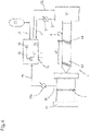
- FIG. 6 shows a highly schematic view of a cyclically operating injection molding machine 1.
- This has a plasticizing unit 43 that can be driven by a drive unit 41.
- a plasticizable injection molding material 5 can be plasticized, processed and homogenized and injected into an injection mold 45 which is hydraulically downstream of this and which is accommodated in a mold closing unit, not shown in the drawing, for opening and closing the injection mold 45.
- the injection molding material 5 is plasticized and injected in a known manner by means of a conveyor such as a worm 49 which is driven by the drive unit 41 and can be moved along a worm path 47.
- the worm path 47 is indicated by a frontmost and rearmost position of the worm 49.
- the injection molding material 5 is injected into at least one cavity 7 of the injection molding tool 45 via injection channels that are not shown in detail. Examples are in 6 two of the cavities 7 are drawn in dashed lines, but more than two cavities can also be provided be.
- an internal mold pressure 3 occurs within the cavity 7 of the injection molding tool 45 as a result of the injected injection molding material 5 .
- the injection pressure 3 can be measured by a sensor device 51 and made available as the actual injection pressure 9 to a control device 53 having a controller 27 .
- the cavity pressure 3a can be measured by means of a further sensor device 51a and made available as the actual cavity pressure 9a.
- Controller 27 generates an actuating signal 55 for setting injection pressure 3 from actual injection pressure 9 and a setpoint value.
- the target injection pressure 13 is specified in the form of a target injection pressure profile 15 that is curved at least approximately in sections.
- Target injection pressure curve 15 is generated and/or selected in particular as a function of operator input 35 by operator 57 . Alternatively or additionally, however, this can take place as a function of at least one measured variable 37 that can be measured on the injection molding machine 1 .
- Measured variable 37 can be any process variable that occurs and/or can be measured on injection molding machine 1 .
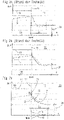
- FIGs 1a and 1b 12 each show curves occurring on an injection molding machine according to the prior art, namely a curve of a target injection pressure 13 and, in response thereto, a curve of an actual injection pressure 9.
- FIG Fig. 1a another snail path 47 drawn.
- Fig. 1a shows at least part of an injection cycle of the injection molding machine. This has an injection phase 59, in which injection molding material is injected into the cavity, and the holding pressure control phase 11 beginning at a switchover point 31. It can be seen that the setpoint injection pressure 13 or injection pressure is set to the actual injection pressure 9 at the switchover point in time 31 and is specified in a ramp-like manner from there.
- the falling ramp ends at the level of a constant predetermined holding pressure level 39 up to the end of the holding pressure control phase 11.
- the actual injection pressure 9 is controlled or adjusted by means of a comparatively hard controller as a function of the target injection pressure 13 . It can be seen that as a result an abrupt drop in actual injection pressure 9 begins at switchover point 31 . At the end of the falling ramp of the setpoint injection pressure 13, there is an overshoot, with the desired holding pressure level 39 being undershot.
- Fig. 1b shows the in Fig. 1a curves shown, the difference being that a comparatively soft controller is used for setting or influencing the actual injection pressure 9 .
- the actual injection pressure is first measured at the switching point 31 and the target injection pressure 13 is set to this value.
- the specification in the form of the ramp falling to the holding pressure level 39 also corresponds to Fig. 1a .
- the comparatively soft controller which therefore has a slower control behavior, the actual injection pressure 9 initially overshoots shortly after the switching point 31, i.e. is further increased, and then with a comparatively large deviation in time and without overshooting is set to the constant holding pressure level 39.
- the according Fig. 1b The controller used therefore has poorer control behavior and therefore lower-vibration control behavior for the constant holding pressure level 39 .
- FIG. 1 shows another possibility for a transition to the holding pressure control phase 11 that is as abrupt as possible according to the prior art.
- the target injection pressure 13 is specified in the form of a step to the holding pressure level 39.
- the actual injection pressure 9 is set according to FIG Figure 2a also with a comparatively hard controller. It can be seen that during a settling time 33, after the end of which the holding pressure level 39 has been adjusted to a tolerable control deviation, a comparatively strong overshoot occurs.
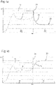
- Figure 2b shows the in Figure 2a curves shown, whereby a comparatively hard controller is also used.
- the target injection pressure 13 is according to Figure 2b similar to the Figures 1a and 1b specified by means of a ramp that falls from the switchover point 31 to the holding pressure level 39 . It can be seen that despite the specification as a ramp, an overshoot occurs after the end of the ramp.
- the controller 27 sets the actual injection pressure 9 with a comparatively smaller deviation 25 from the setpoint injection pressure profile 15 in the sense of a master controller. After the time period 29 has elapsed, the controller 27 acts as a stationary controller due to the constant specification of the holding pressure level 39, with FIG Figure 2c minimal overshoot occurs. It is possible to select the period of time 29 so large that there is no longer any overshoot when the transition to the holding pressure level 39 occurs. Alternatively or additionally, it is conceivable to also lead the second derivative 19 to the value zero, so that an even smoother transition to the holding pressure level 39 is possible. In particular, it is possible to adapt the period of time 29 to a settling time 33 of the controller 27 .
- the settling time 33 of the controller 27 is, for example, half in Figure 2a shown, for example as a time to adjust after a setpoint jump.
- a stationary state 23 follows, in which the actual injection pressure 9 is regulated to the constant holding pressure level 39 .
- an abrupt transition into the holding pressure control phase 11 can be generated at the switchover time 31, with an overshoot after the time period 29 has expired being avoidable as best as possible or at least being reduced to a minimum.
- the length of the period of time 29 can be made dependent, for example, on how well a lagging cavity 7 of the injection mold 45 can still be filled. Good control behavior results, for example, when the period of time 29 is at least 0.5 to 5 times the settling time 33 of the controller 27 .
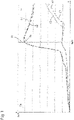
- FIG. 3 shows a total of four actual mold cavity pressure curves as an example for two cavities of a multi-cavity mold, each according to the prior art with a linear ramp as the default value and the in Figure 2c described setpoint specification according to the invention in the form of the setpoint injection pressure profile 15.
- the setpoint specifications are in 3 not shown to improve clarity.
- the switchover point 31 at which the injection molding machine 1 is switched over to the holding pressure control phase 11 can be seen.
- a course of the actual cavity pressure 9a after switching according to the invention by means of the target injection pressure course 15 of a leading cavity 7 is shown by means of a first dashed curve 61 printed in bold.
- the corresponding course of the actual cavity pressure 9a of a lagging cavity in is shown by means of a second normally printed dashed curve 63 3 shown.
- the actual internal mold pressure is plotted by means of a dot-dash third curve 65 printed in bold, as it results when switching over a linear ramp known from the prior art.
- the actual internal mold pressure according to the prior art of the lagging cavity is shown by means of a faintly printed dash-dotted fourth curve 67 .
- the leading cavity ie the first curve 61 and the third curve 65 according to the prior art, pass through a pressure peak of almost the same size shortly after the switchover time 31 .
- a desired abrupt switchover to the holding pressure control phase 11 which avoids pressure peaks, takes place.
- Fourth curve 67 shows that the lagging cavity in a switchover according to the prior art, starting from a value of actual injection pressure 9 at switchover time 31 , first falls and is then brought to holding pressure level 39 .
- the second curve 63 of the trailing cavity runs approximately horizontally, starting from the actual cavity pressure 9 at the switchover time 31 , ie without falling significantly, and is then also set to the holding pressure level 39 .
- the second curve 63 according to the invention and the fourth curve 67 according to the prior art span a surface 69 .
- This area 69 can be used as a parameter for determining an improvement in the process by using the target injection pressure curve 15 according to the invention.
- a difference between the curves 63 and 67 at a specific point in time after the switching point 31 can also be used as the parameter.
- the increase in pressure in the lagging cavity occurs significantly earlier when using the setpoint injection pressure profile 15 according to the invention than in the case of the linear holding pressure ramp according to the prior art. This is due to the smooth transition into the Packing level 39 possible.
- the behavior is therefore as soft as possible, in particular in the sense of a bionic transition at the end of the transition phase into the holding pressure level 39, ie in particular at the end of the time period 29, which leads to a process-compensating behavior.
- filling differences between the leading and the trailing cavity can be compensated for.
Landscapes
- Engineering & Computer Science (AREA)
- Manufacturing & Machinery (AREA)
- Mechanical Engineering (AREA)
- Injection Moulding Of Plastics Or The Like (AREA)
Claims (14)
- Procédé de commande et de réglage d'une pression (3,3a) d'une machine de moulage par injection à fonctionnement cyclique (1), comportant les étapes suivantes :- mise à disposition d'un matériau pour moulage par injection plastifié (5),- remplissage d'au moins une cavité (7) avec le matériau pour moulage par injection (5),- saisie d'une pression courante (9,9a),- commutation sur une phase de réglage de réimpression (11) à un moment de commutation (31),- à partir d'une pression courante (9, 9a) mesurée au moment de commutation (31), prédéfinition d'une forme de courbure d'une pression de consigne (13) pour une transition dans la phase de réglage de réimpression (11), en tant que fonction mathématique pour la production d'au moins d'une évolution de pression de consigne (15) courbée au moins par intermittence, la fonction mathématique qui définit la courbure étant fixée, déterminée et/ou calculée,- dans lequel un laps de temps (29) depuis le moment de commutation (31) sur la phase de réglage de réimpression (11) jusqu'à l'atteinte d'un profil de réglage de réimpression de la phase de réglage de réimpression (11) est prédéfini en fonction d'au moins un paramètre et/ou d'une saisie d'utilisateur (35) et- dans lequel une augmentation initiale (21) de l'évolution de la pression de consigne (15) est prédéfinie au moment de commutation (31).
- Procédé selon la revendication 1, caractérisé par :- la prédéfinition de sections partielles d'un tracé polygonal pour la production de l'évolution de la pression de consigne (15).
- Procédé selon la revendication 1 ou 2, caractérisé par :- la production d'une transition abrupte ou la production d'une transition fluide dans la phase de réglage de réimpression (11) au moyen de l'évolution de la pression de consigne (15).
- Procédé selon l'une des revendications précédentes, caractérisé par :- la production d'une transition fluide dans un état stationnaire (23) de la phase de réglage de réimpression (11) et/ou dans un profil de réglage de réimpression programmé de la phase de réglage de réimpression (11) au moyen de l'évolution de la pression de consigne (15).
- Procédé selon l'une des revendications précédentes, caractérisé en ce que la pression courante (9,9a) suit de manière apériodique l'évolution de la pression de consigne (15).
- Procédé selon l'une des revendications précédentes, caractérisé par :- la saisie de la pression courante en tant que pression interne courante d'outil (9a) en fonction d'une évolution de pression d'injection de consigne (15) incurvée en tant qu'évolution de pression (15),- la saisie de la pression interne courante d'outil (9a) en fonction d'une rampe de pression d'injection de consigne linéaire ou d'un palier,- la saisie d'une grandeur de référence donnant une amélioration du procédé en fonction de la pression interne courante d'outil (9a) saisie précitée.
- Procédé selon l'une des revendications précédentes, caractérisé par :- la mise à disposition d'un dispositif de réglage (27) pour la phase de réglage de réimpression (11),- l'utilisation inchangée du dispositif de réglage (27) en tant que dispositif de réglage de guidage, tant qu'une première dérivation (17) de l'évolution de pression de consigne (15) est différente de zéro ou d'une valeur constante, et en tant que dispositif de réglage stationnaire, dès que la première dérivation (17) reste à la valeur zéro.
- Procédé selon l'une des revendications précédentes, caractérisé par :- la prédéfinition, la saisie, la détermination, la fixation, le calcul ou le choix d'une évolution de pression de consigne (15) en fonction d'au moins un paramètre de la machine de moulage par injection (1) et/ou de la saisie de l'utilisateur (35) et/ou d'une valeur de référence.
- Procédé selon l'une des revendications précédentes, caractérisé en ce que le laps de temps (29) depuis le moment de commutation (31) dans la phase de réglage de réimpression (11) jusqu'à la première dérivation (17) de l'évolution de pression de consigne (15) reste à la valeur zéro et/ou est pré-définissable jusqu'à l'atteinte d'un niveau de réimpression (39) en fonction du ou des paramètre(s) et/ou de la saisie d'utilisateur (35).
- Procédé selon la revendication 8 ou 9, caractérisé par l'une au moins des données suivantes au choix, au moyen de l'évolution de pression de consigne (15) en fonction du paramètre et/ou de la saisie d'utilisateur (35) et/ou de la valeur de référence :- la modification de la fonction mathématique prédéfinissant l'évolution de la pression de consigne (15),- la production de la transition abrupte ou fluide dans la phase de réglage de réimpression (11),- la modification d'un ordre mathématique d'une fonction mathématique définissant l'évolution de pression de consigne (15) de n-ième ordre,- la prédéfinition d'une augmentation initiale (21) de l'évolution de pression de consigne (15) au moment de commutation (31),- la prédéfinition d'une dérivation d'ordre m ou d'une évolution de la dérivation d'ordre m de l'évolution de pression de consigne (15), dans laquelle m est inférieur à n.
- Procédé selon l'une des revendications 8 à 10, caractérisé par l'une au moins des étapes suivantes :- saisie d'une valeur de référence en fonction de la pression courante (9,9a),- saisie d'une évolution de la pression courante (9,9a) et saisie de la valeur de référence en fonction de l'évolution,- saisie de la valeur de référence en fonction la pression courante (9,9a) par rapport à l'évolution de la pression de consigne (15),- saisie de la valeur de référence en fonction d'un dépassement ou d'une diminution de la pression courante (9,9a),- saisie de la valeur de référence en fonction d'une évolution apériodique de la pression courante (9,9a),- choix ou réglage ou prédéfinition de l'évolution de pression de consigne (15) en fonction de la valeur de référence.
- Procédé selon l'une des revendications précédentes, caractérisé par :- la mise à disposition de l'évolution de pression de consigne (15) par addition d'une fonction de courbure à un niveau de réimpression (39) se trouvant à la base du réglage de réimpression en tant que valeur de consigne stationnaire et/ou à un profil de réimpression de la phase de réglage de réimpression (11) et/ou la mise à disposition de l'évolution de la pression de consigne (15) pour la totalité de la phase de réglage de réimpression (11).
- Dispositif de réglage (27), installé, réglé, construit et/ou programmé pour la mise en œuvre d'un procédé selon l'une des revendications 1 à 12.
- Machine de moulage par injection (1), installée, conçue, construite et/ou programmée pour la mise en oeuvre d'un procédé selon l'une des revendications 1 à 12 et/ou avec un dispositif de réglage (27) selon la revendication 13.
Applications Claiming Priority (2)
| Application Number | Priority Date | Filing Date | Title |
|---|---|---|---|
| DE102017207586.4A DE102017207586A1 (de) | 2017-05-05 | 2017-05-05 | STEUERN UND REGELN DES DRUCKS EINER ZYKLISCH ARBEITENDEN SPRITZGIEßMASCHINE |
| PCT/EP2018/061342 WO2018202773A1 (fr) | 2017-05-05 | 2018-05-03 | Commande et réglage de la pression d'une machine de moulage par injection à fonctionnement cyclique |
Publications (2)
| Publication Number | Publication Date |
|---|---|
| EP3619023A1 EP3619023A1 (fr) | 2020-03-11 |
| EP3619023B1 true EP3619023B1 (fr) | 2022-06-22 |
Family
ID=62104308
Family Applications (1)
| Application Number | Title | Priority Date | Filing Date |
|---|---|---|---|
| EP18721795.5A Active EP3619023B1 (fr) | 2017-05-05 | 2018-05-03 | Commande et réglage de la pression d'une machine de moulage par injection à fonctionnement cyclique |
Country Status (3)
| Country | Link |
|---|---|
| EP (1) | EP3619023B1 (fr) |
| DE (1) | DE102017207586A1 (fr) |
| WO (1) | WO2018202773A1 (fr) |
Cited By (1)
| Publication number | Priority date | Publication date | Assignee | Title |
|---|---|---|---|---|
| CN117245873A (zh) * | 2023-11-14 | 2023-12-19 | 广东美的制冷设备有限公司 | 注塑机初始工艺参数的确定方法、装置及注塑机 |
Families Citing this family (5)
| Publication number | Priority date | Publication date | Assignee | Title |
|---|---|---|---|---|
| DE102018126313A1 (de) * | 2018-10-23 | 2020-04-23 | Kraussmaffei Technologies Gmbh | Verfahren zum Betreiben einer Spritzgießmaschine, insbesondere hinsichtlich verbesserter konstanter Werkzeugfüllung, sowie Spritzgießmaschine zur Durchführung des Verfahrens |
| WO2020209291A1 (fr) * | 2019-04-09 | 2020-10-15 | 日精エー・エス・ビー機械株式会社 | Dispositif de fabrication d'article moulé en résine, et procédé de commande de dispositif de fabrication |
| CN111831022B (zh) * | 2019-04-18 | 2022-03-18 | 北京七星华创流量计有限公司 | 腔室压力控制方法及装置、半导体设备 |
| CN114077221A (zh) * | 2020-08-14 | 2022-02-22 | 中国科学院理化技术研究所 | 基于控制器的多段曲线控制实现方法及装置 |
| CN119458826B (zh) * | 2024-11-23 | 2025-11-21 | 宁波创基机械股份有限公司 | 一种注塑机的注塑控制方法、系统、存储介质及注塑机 |
Citations (2)
| Publication number | Priority date | Publication date | Assignee | Title |
|---|---|---|---|---|
| US4968462A (en) * | 1987-01-30 | 1990-11-06 | Sumitomo Heavy Industries, Ltd. | Method and apparatus for setting injection pressure of injection molding machine |
| EP0531532A1 (fr) * | 1991-01-14 | 1993-03-17 | Fanuc Ltd. | Procede de determination de la forme d'onde de pression pour le reglage de la pression d'injection dans une machine de moulage par injection |
Family Cites Families (9)
| Publication number | Priority date | Publication date | Assignee | Title |
|---|---|---|---|---|
| DE19525141C1 (de) * | 1995-07-11 | 1996-11-28 | Karl Hehl | Verfahren zur Regelung oder Steuerung einer Kunststoff-Spritzgießmaschine |
| DE19536566C1 (de) * | 1995-10-02 | 1997-02-06 | Arburg Gmbh & Co | Verfahren zur Regelung des Werkzeuginnendrucks an einer zyklisch arbeitenden Maschine |
| ATE320904T1 (de) * | 1997-08-21 | 2006-04-15 | Kistler Holding Ag | Verfahren zum regeln einer spritzgiessanlage für kunststoff-materialien |
| JP3240515B2 (ja) * | 1998-12-10 | 2001-12-17 | 住友重機械工業株式会社 | 射出成形機の射出制御方法 |
| JP3440413B2 (ja) * | 2000-06-12 | 2003-08-25 | 住友重機械工業株式会社 | 高速射出・高速圧抜きにおけるスクリュ位置制御方法 |
| TWI232162B (en) * | 2003-04-04 | 2005-05-11 | Sumitomo Heavy Industries | Injection-molding machine and method of controlling injection-molding machine |
| EP2174769A1 (fr) * | 2008-10-07 | 2010-04-14 | Neo-plastic Dr. Doetsch Diespeck GmbH | Procédé de moulage par injection et installation correspondante |
| AT514232B1 (de) * | 2013-04-18 | 2015-04-15 | Engel Austria Gmbh | Verfahren zum Steuern oder Regeln einer Spritzgießmaschine |
| JP5815646B2 (ja) * | 2013-11-15 | 2015-11-17 | ファナック株式会社 | 射出成形機の制御装置 |
-
2017
- 2017-05-05 DE DE102017207586.4A patent/DE102017207586A1/de not_active Withdrawn
-
2018
- 2018-05-03 WO PCT/EP2018/061342 patent/WO2018202773A1/fr not_active Ceased
- 2018-05-03 EP EP18721795.5A patent/EP3619023B1/fr active Active
Patent Citations (2)
| Publication number | Priority date | Publication date | Assignee | Title |
|---|---|---|---|---|
| US4968462A (en) * | 1987-01-30 | 1990-11-06 | Sumitomo Heavy Industries, Ltd. | Method and apparatus for setting injection pressure of injection molding machine |
| EP0531532A1 (fr) * | 1991-01-14 | 1993-03-17 | Fanuc Ltd. | Procede de determination de la forme d'onde de pression pour le reglage de la pression d'injection dans une machine de moulage par injection |
Cited By (2)
| Publication number | Priority date | Publication date | Assignee | Title |
|---|---|---|---|---|
| CN117245873A (zh) * | 2023-11-14 | 2023-12-19 | 广东美的制冷设备有限公司 | 注塑机初始工艺参数的确定方法、装置及注塑机 |
| CN117245873B (zh) * | 2023-11-14 | 2024-04-05 | 广东美的制冷设备有限公司 | 注塑机初始工艺参数的确定方法、装置及注塑机 |
Also Published As
| Publication number | Publication date |
|---|---|
| EP3619023A1 (fr) | 2020-03-11 |
| DE102017207586A1 (de) | 2018-11-08 |
| WO2018202773A1 (fr) | 2018-11-08 |
Similar Documents
| Publication | Publication Date | Title |
|---|---|---|
| EP3619023B1 (fr) | Commande et réglage de la pression d'une machine de moulage par injection à fonctionnement cyclique | |
| EP3055116B1 (fr) | Procédé de guidage du processus d'un cycle de remplissage d'un moule d'une machine de moulage par injection | |
| DE3884406T2 (de) | Regeleinheit für einspritzgiessvorrichtung. | |
| EP0854778A2 (fr) | Procede de regulation de la courbe de pression interne d'outils dans une machine a fonctionnement cyclique | |
| DE69113869T2 (de) | Spritzgiesssteuerung mit prozessvariablem Lernverfahren. | |
| EP3057760B1 (fr) | Procédé permettant d'évaluer les propriétés techniques d'outils de moulage par injection | |
| DE69125645T2 (de) | Spritzgiesssteuereinrichtung mit wählbaren Kontrollfunktionen | |
| EP3359365B1 (fr) | Procédé pour la détermination d'un volume réel d'une masse moulable par injection dans une opération de moulage par injection | |
| DE19952708B4 (de) | Einspritzsteuerverfahren und Einrichtung einer Druckgussmaschine | |
| DE102014008055B4 (de) | Drucksteuervorrichtung einer Spritzgießmaschine | |
| DE602004002820T2 (de) | Regelung der Düsenanpresskraft | |
| AT514847B1 (de) | Verfahren zur Bestimmung eines Sollwerts für einen Einstellparameter | |
| EP2974998A1 (fr) | Dispositif et procede de remplissage d'un recipient avec un produit de remplissage | |
| WO2010040463A1 (fr) | Procédé de moulage par injection et installation associée | |
| DE102016001039B4 (de) | Verfahren zum Betrieb eines Einspritzaggregats und Einspritzaggregat | |
| DE19616383B4 (de) | Verfahren und Vorrichtung zum Steuern der Einspritzgeschwindigkeit von Spritzgießmaschinen | |
| DE102004051109B4 (de) | Verfahren zum Betrieb einer Spritzgießmaschine | |
| AT514232B1 (de) | Verfahren zum Steuern oder Regeln einer Spritzgießmaschine | |
| AT521442B1 (de) | Dynamische Anpassung der Schließkraft | |
| DE102015008950A1 (de) | Drucksteuervorrichtung einer Spritzgiessmaschine | |
| WO2024083675A1 (fr) | Commande de mesure synchronisée par moteurs et machine de moulage par injection actionnée en fonction de ladite commande | |
| DE102007035804B3 (de) | Steuerungsverfahren für eine Kunststoffspritzgießmaschine zum Ausgleich von Chargenschwankungen | |
| DE2639938A1 (de) | Verfahren zur herstellung von formteilen aus formbaren werkstoffen auf spritzgiessmaschinen | |
| DE112021008233T5 (de) | Fernsteuerung für rückkopplungssteuerung und verfahren dafür | |
| EP2485881A1 (fr) | Procédé pour réguler la fabrication d'un produit |
Legal Events
| Date | Code | Title | Description |
|---|---|---|---|
| STAA | Information on the status of an ep patent application or granted ep patent |
Free format text: STATUS: UNKNOWN |
|
| STAA | Information on the status of an ep patent application or granted ep patent |
Free format text: STATUS: THE INTERNATIONAL PUBLICATION HAS BEEN MADE |
|
| PUAI | Public reference made under article 153(3) epc to a published international application that has entered the european phase |
Free format text: ORIGINAL CODE: 0009012 |
|
| STAA | Information on the status of an ep patent application or granted ep patent |
Free format text: STATUS: REQUEST FOR EXAMINATION WAS MADE |
|
| 17P | Request for examination filed |
Effective date: 20191204 |
|
| AK | Designated contracting states |
Kind code of ref document: A1 Designated state(s): AL AT BE BG CH CY CZ DE DK EE ES FI FR GB GR HR HU IE IS IT LI LT LU LV MC MK MT NL NO PL PT RO RS SE SI SK SM TR |
|
| AX | Request for extension of the european patent |
Extension state: BA ME |
|
| DAV | Request for validation of the european patent (deleted) | ||
| DAX | Request for extension of the european patent (deleted) | ||
| STAA | Information on the status of an ep patent application or granted ep patent |
Free format text: STATUS: EXAMINATION IS IN PROGRESS |
|
| 17Q | First examination report despatched |
Effective date: 20201009 |
|
| GRAP | Despatch of communication of intention to grant a patent |
Free format text: ORIGINAL CODE: EPIDOSNIGR1 |
|
| STAA | Information on the status of an ep patent application or granted ep patent |
Free format text: STATUS: GRANT OF PATENT IS INTENDED |
|
| INTG | Intention to grant announced |
Effective date: 20220111 |
|
| GRAS | Grant fee paid |
Free format text: ORIGINAL CODE: EPIDOSNIGR3 |
|
| GRAA | (expected) grant |
Free format text: ORIGINAL CODE: 0009210 |
|
| STAA | Information on the status of an ep patent application or granted ep patent |
Free format text: STATUS: THE PATENT HAS BEEN GRANTED |
|
| AK | Designated contracting states |
Kind code of ref document: B1 Designated state(s): AL AT BE BG CH CY CZ DE DK EE ES FI FR GB GR HR HU IE IS IT LI LT LU LV MC MK MT NL NO PL PT RO RS SE SI SK SM TR |
|
| REG | Reference to a national code |
Ref country code: GB Ref legal event code: FG4D Free format text: NOT ENGLISH |
|
| REG | Reference to a national code |
Ref country code: CH Ref legal event code: EP |
|
| REG | Reference to a national code |
Ref country code: DE Ref legal event code: R096 Ref document number: 502018009982 Country of ref document: DE |
|
| REG | Reference to a national code |
Ref country code: AT Ref legal event code: REF Ref document number: 1499499 Country of ref document: AT Kind code of ref document: T Effective date: 20220715 |
|
| REG | Reference to a national code |
Ref country code: IE Ref legal event code: FG4D Free format text: LANGUAGE OF EP DOCUMENT: GERMAN |
|
| REG | Reference to a national code |
Ref country code: NL Ref legal event code: FP |
|
| REG | Reference to a national code |
Ref country code: LT Ref legal event code: MG9D |
|
| PG25 | Lapsed in a contracting state [announced via postgrant information from national office to epo] |
Ref country code: SE Free format text: LAPSE BECAUSE OF FAILURE TO SUBMIT A TRANSLATION OF THE DESCRIPTION OR TO PAY THE FEE WITHIN THE PRESCRIBED TIME-LIMIT Effective date: 20220622 Ref country code: NO Free format text: LAPSE BECAUSE OF FAILURE TO SUBMIT A TRANSLATION OF THE DESCRIPTION OR TO PAY THE FEE WITHIN THE PRESCRIBED TIME-LIMIT Effective date: 20220922 Ref country code: LT Free format text: LAPSE BECAUSE OF FAILURE TO SUBMIT A TRANSLATION OF THE DESCRIPTION OR TO PAY THE FEE WITHIN THE PRESCRIBED TIME-LIMIT Effective date: 20220622 Ref country code: HR Free format text: LAPSE BECAUSE OF FAILURE TO SUBMIT A TRANSLATION OF THE DESCRIPTION OR TO PAY THE FEE WITHIN THE PRESCRIBED TIME-LIMIT Effective date: 20220622 Ref country code: GR Free format text: LAPSE BECAUSE OF FAILURE TO SUBMIT A TRANSLATION OF THE DESCRIPTION OR TO PAY THE FEE WITHIN THE PRESCRIBED TIME-LIMIT Effective date: 20220923 Ref country code: FI Free format text: LAPSE BECAUSE OF FAILURE TO SUBMIT A TRANSLATION OF THE DESCRIPTION OR TO PAY THE FEE WITHIN THE PRESCRIBED TIME-LIMIT Effective date: 20220622 Ref country code: BG Free format text: LAPSE BECAUSE OF FAILURE TO SUBMIT A TRANSLATION OF THE DESCRIPTION OR TO PAY THE FEE WITHIN THE PRESCRIBED TIME-LIMIT Effective date: 20220922 |
|
| PG25 | Lapsed in a contracting state [announced via postgrant information from national office to epo] |
Ref country code: RS Free format text: LAPSE BECAUSE OF FAILURE TO SUBMIT A TRANSLATION OF THE DESCRIPTION OR TO PAY THE FEE WITHIN THE PRESCRIBED TIME-LIMIT Effective date: 20220622 Ref country code: LV Free format text: LAPSE BECAUSE OF FAILURE TO SUBMIT A TRANSLATION OF THE DESCRIPTION OR TO PAY THE FEE WITHIN THE PRESCRIBED TIME-LIMIT Effective date: 20220622 |
|
| PG25 | Lapsed in a contracting state [announced via postgrant information from national office to epo] |
Ref country code: SM Free format text: LAPSE BECAUSE OF FAILURE TO SUBMIT A TRANSLATION OF THE DESCRIPTION OR TO PAY THE FEE WITHIN THE PRESCRIBED TIME-LIMIT Effective date: 20220622 Ref country code: SK Free format text: LAPSE BECAUSE OF FAILURE TO SUBMIT A TRANSLATION OF THE DESCRIPTION OR TO PAY THE FEE WITHIN THE PRESCRIBED TIME-LIMIT Effective date: 20220622 Ref country code: RO Free format text: LAPSE BECAUSE OF FAILURE TO SUBMIT A TRANSLATION OF THE DESCRIPTION OR TO PAY THE FEE WITHIN THE PRESCRIBED TIME-LIMIT Effective date: 20220622 Ref country code: PT Free format text: LAPSE BECAUSE OF FAILURE TO SUBMIT A TRANSLATION OF THE DESCRIPTION OR TO PAY THE FEE WITHIN THE PRESCRIBED TIME-LIMIT Effective date: 20221024 Ref country code: ES Free format text: LAPSE BECAUSE OF FAILURE TO SUBMIT A TRANSLATION OF THE DESCRIPTION OR TO PAY THE FEE WITHIN THE PRESCRIBED TIME-LIMIT Effective date: 20220622 Ref country code: EE Free format text: LAPSE BECAUSE OF FAILURE TO SUBMIT A TRANSLATION OF THE DESCRIPTION OR TO PAY THE FEE WITHIN THE PRESCRIBED TIME-LIMIT Effective date: 20220622 Ref country code: CZ Free format text: LAPSE BECAUSE OF FAILURE TO SUBMIT A TRANSLATION OF THE DESCRIPTION OR TO PAY THE FEE WITHIN THE PRESCRIBED TIME-LIMIT Effective date: 20220622 |
|
| PG25 | Lapsed in a contracting state [announced via postgrant information from national office to epo] |
Ref country code: PL Free format text: LAPSE BECAUSE OF FAILURE TO SUBMIT A TRANSLATION OF THE DESCRIPTION OR TO PAY THE FEE WITHIN THE PRESCRIBED TIME-LIMIT Effective date: 20220622 Ref country code: IS Free format text: LAPSE BECAUSE OF FAILURE TO SUBMIT A TRANSLATION OF THE DESCRIPTION OR TO PAY THE FEE WITHIN THE PRESCRIBED TIME-LIMIT Effective date: 20221022 |
|
| REG | Reference to a national code |
Ref country code: DE Ref legal event code: R097 Ref document number: 502018009982 Country of ref document: DE |
|
| PG25 | Lapsed in a contracting state [announced via postgrant information from national office to epo] |
Ref country code: AL Free format text: LAPSE BECAUSE OF FAILURE TO SUBMIT A TRANSLATION OF THE DESCRIPTION OR TO PAY THE FEE WITHIN THE PRESCRIBED TIME-LIMIT Effective date: 20220622 |
|
| PG25 | Lapsed in a contracting state [announced via postgrant information from national office to epo] |
Ref country code: DK Free format text: LAPSE BECAUSE OF FAILURE TO SUBMIT A TRANSLATION OF THE DESCRIPTION OR TO PAY THE FEE WITHIN THE PRESCRIBED TIME-LIMIT Effective date: 20220622 |
|
| PLBE | No opposition filed within time limit |
Free format text: ORIGINAL CODE: 0009261 |
|
| STAA | Information on the status of an ep patent application or granted ep patent |
Free format text: STATUS: NO OPPOSITION FILED WITHIN TIME LIMIT |
|
| 26N | No opposition filed |
Effective date: 20230323 |
|
| P01 | Opt-out of the competence of the unified patent court (upc) registered |
Effective date: 20230518 |
|
| PG25 | Lapsed in a contracting state [announced via postgrant information from national office to epo] |
Ref country code: SI Free format text: LAPSE BECAUSE OF FAILURE TO SUBMIT A TRANSLATION OF THE DESCRIPTION OR TO PAY THE FEE WITHIN THE PRESCRIBED TIME-LIMIT Effective date: 20220622 |
|
| PG25 | Lapsed in a contracting state [announced via postgrant information from national office to epo] |
Ref country code: MC Free format text: LAPSE BECAUSE OF FAILURE TO SUBMIT A TRANSLATION OF THE DESCRIPTION OR TO PAY THE FEE WITHIN THE PRESCRIBED TIME-LIMIT Effective date: 20220622 |
|
| REG | Reference to a national code |
Ref country code: BE Ref legal event code: MM Effective date: 20230531 |
|
| PG25 | Lapsed in a contracting state [announced via postgrant information from national office to epo] |
Ref country code: MC Free format text: LAPSE BECAUSE OF FAILURE TO SUBMIT A TRANSLATION OF THE DESCRIPTION OR TO PAY THE FEE WITHIN THE PRESCRIBED TIME-LIMIT Effective date: 20220622 Ref country code: LU Free format text: LAPSE BECAUSE OF NON-PAYMENT OF DUE FEES Effective date: 20230503 |
|
| REG | Reference to a national code |
Ref country code: IE Ref legal event code: MM4A |
|
| PG25 | Lapsed in a contracting state [announced via postgrant information from national office to epo] |
Ref country code: IE Free format text: LAPSE BECAUSE OF NON-PAYMENT OF DUE FEES Effective date: 20230503 |
|
| PG25 | Lapsed in a contracting state [announced via postgrant information from national office to epo] |
Ref country code: IE Free format text: LAPSE BECAUSE OF NON-PAYMENT OF DUE FEES Effective date: 20230503 |
|
| PG25 | Lapsed in a contracting state [announced via postgrant information from national office to epo] |
Ref country code: BE Free format text: LAPSE BECAUSE OF NON-PAYMENT OF DUE FEES Effective date: 20230531 |
|
| PG25 | Lapsed in a contracting state [announced via postgrant information from national office to epo] |
Ref country code: BG Free format text: LAPSE BECAUSE OF FAILURE TO SUBMIT A TRANSLATION OF THE DESCRIPTION OR TO PAY THE FEE WITHIN THE PRESCRIBED TIME-LIMIT Effective date: 20220622 |
|
| PG25 | Lapsed in a contracting state [announced via postgrant information from national office to epo] |
Ref country code: BG Free format text: LAPSE BECAUSE OF FAILURE TO SUBMIT A TRANSLATION OF THE DESCRIPTION OR TO PAY THE FEE WITHIN THE PRESCRIBED TIME-LIMIT Effective date: 20220622 |
|
| PGFP | Annual fee paid to national office [announced via postgrant information from national office to epo] |
Ref country code: NL Payment date: 20250522 Year of fee payment: 8 |
|
| PGFP | Annual fee paid to national office [announced via postgrant information from national office to epo] |
Ref country code: DE Payment date: 20250429 Year of fee payment: 8 |
|
| PGFP | Annual fee paid to national office [announced via postgrant information from national office to epo] |
Ref country code: GB Payment date: 20250522 Year of fee payment: 8 |
|
| PGFP | Annual fee paid to national office [announced via postgrant information from national office to epo] |
Ref country code: IT Payment date: 20250530 Year of fee payment: 8 |
|
| PGFP | Annual fee paid to national office [announced via postgrant information from national office to epo] |
Ref country code: FR Payment date: 20250526 Year of fee payment: 8 |
|
| PGFP | Annual fee paid to national office [announced via postgrant information from national office to epo] |
Ref country code: CH Payment date: 20250601 Year of fee payment: 8 |
|
| PGFP | Annual fee paid to national office [announced via postgrant information from national office to epo] |
Ref country code: AT Payment date: 20250519 Year of fee payment: 8 |
|
| PG25 | Lapsed in a contracting state [announced via postgrant information from national office to epo] |
Ref country code: CY Free format text: LAPSE BECAUSE OF FAILURE TO SUBMIT A TRANSLATION OF THE DESCRIPTION OR TO PAY THE FEE WITHIN THE PRESCRIBED TIME-LIMIT; INVALID AB INITIO Effective date: 20180503 |
|
| PG25 | Lapsed in a contracting state [announced via postgrant information from national office to epo] |
Ref country code: HU Free format text: LAPSE BECAUSE OF FAILURE TO SUBMIT A TRANSLATION OF THE DESCRIPTION OR TO PAY THE FEE WITHIN THE PRESCRIBED TIME-LIMIT; INVALID AB INITIO Effective date: 20180503 |
|
| PG25 | Lapsed in a contracting state [announced via postgrant information from national office to epo] |
Ref country code: TR Free format text: LAPSE BECAUSE OF FAILURE TO SUBMIT A TRANSLATION OF THE DESCRIPTION OR TO PAY THE FEE WITHIN THE PRESCRIBED TIME-LIMIT Effective date: 20220622 |