EP3619083B1 - Dispositif pour enregistrer et mesurer la poussière des freins - Google Patents
Dispositif pour enregistrer et mesurer la poussière des freins Download PDFInfo
- Publication number
- EP3619083B1 EP3619083B1 EP18720761.8A EP18720761A EP3619083B1 EP 3619083 B1 EP3619083 B1 EP 3619083B1 EP 18720761 A EP18720761 A EP 18720761A EP 3619083 B1 EP3619083 B1 EP 3619083B1
- Authority
- EP
- European Patent Office
- Prior art keywords
- brake
- measuring
- air duct
- exhaust air
- dust particles
- Prior art date
- Legal status (The legal status is an assumption and is not a legal conclusion. Google has not performed a legal analysis and makes no representation as to the accuracy of the status listed.)
- Active
Links
Images
Classifications
-
- B—PERFORMING OPERATIONS; TRANSPORTING
- B60—VEHICLES IN GENERAL
- B60T—VEHICLE BRAKE CONTROL SYSTEMS OR PARTS THEREOF; BRAKE CONTROL SYSTEMS OR PARTS THEREOF, IN GENERAL; ARRANGEMENT OF BRAKING ELEMENTS ON VEHICLES IN GENERAL; PORTABLE DEVICES FOR PREVENTING UNWANTED MOVEMENT OF VEHICLES; VEHICLE MODIFICATIONS TO FACILITATE COOLING OF BRAKES
- B60T17/00—Component parts, details, or accessories of power brake systems not covered by groups B60T8/00, B60T13/00 or B60T15/00, or presenting other characteristic features
- B60T17/18—Safety devices; Monitoring
- B60T17/22—Devices for monitoring or checking brake systems; Signal devices
-
- G—PHYSICS
- G01—MEASURING; TESTING
- G01N—INVESTIGATING OR ANALYSING MATERIALS BY DETERMINING THEIR CHEMICAL OR PHYSICAL PROPERTIES
- G01N15/00—Investigating characteristics of particles; Investigating permeability, pore-volume or surface-area of porous materials
- G01N15/02—Investigating particle size or size distribution
-
- G—PHYSICS
- G01—MEASURING; TESTING
- G01N—INVESTIGATING OR ANALYSING MATERIALS BY DETERMINING THEIR CHEMICAL OR PHYSICAL PROPERTIES
- G01N15/00—Investigating characteristics of particles; Investigating permeability, pore-volume or surface-area of porous materials
- G01N2015/0042—Investigating dispersion of solids
- G01N2015/0046—Investigating dispersion of solids in gas, e.g. smoke
Definitions
- the invention relates to a device for detecting and measuring brake dust and a brake test bench.
- brake dust can also lead to heavy soiling of the wheel rims, which at least has aesthetic disadvantages and can spoil the overall visual impression of a vehicle.
- Measuring devices are known to detect, quantify and determine the size of the above-mentioned brake dust particles.
- the invention is based on the object of providing an improved device for detecting and measuring brake dust.
- the device can be used at an early stage in the design of a vehicle's braking system.
- the measuring device for detecting brake dust works in conjunction with a dynamic brake test bench, where the brake to be tested is actuated, for example, with an electric brake actuator.
- the measuring device is part of the overall application and can therefore be operated as part of the brake test bench.
- the measurement of brake dust particles can be performed in real time with multiple readings per second.
- the appropriate measurement procedure for this purpose includes an automated program with defined load cycles, which are applied to the braking system in the brake test bench. This allows the brake dust particles to be reproducibly detected and measured in conjunction with the respective loads acting on the brake.
- the measuring point can be located in the exhaust air duct of a blower system, which generates a cooling air flow to cool the brakes during testing.
- the brake dust particles are then transported by the air flow through the exhaust air duct of the blower system to the actual measuring point.
- This measuring point is located at a defined location in the exhaust air duct. There, the particles are collected by the measuring system, e.g., via a hose, a heated hose, or a heated hose with cold air, and fed to the particle measuring device.
- the particle measuring device is capable of counting particles and determining their size and size distribution.
- This device can be a well-known device for measuring small or very fine particles, such as a device used in exhaust gas analysis, e.g., for measuring particles in diesel exhaust. Such devices are well-known and will therefore not be discussed in detail here.
- the particle measuring device can communicate with the brake test bench, allowing measurements to be synchronized with the brake test using load profiles. This allows the particle measuring device's measurement results to always be assigned to the respective brake loads on the brake test bench.
- the exhaust duct thus also functions as a dilution channel or tunnel. This prevents the formation of clumps or conglomerates of the brake dust particles, which could adversely affect the measurement result. would distort the results or significantly impair the reproducibility of the measurement.
- Measurement accuracy can thus be significantly improved by using an exhaust air duct that achieves a dilution effect.
- the exhaust air duct must therefore be designed to reliably achieve the desired dilution effect. Simply discharging the cooling air flow from the test chamber is therefore not sufficient. Rather, the exhaust air duct should be dimensioned to enable the dilution effect.
- the exhaust air duct is made of a non-corrosive, electrically conductive material. If necessary, the entire exhaust air duct must be heated to prevent particle clumping.
- the volume flow in the exhaust air duct can be measured using a suitable volume flow measuring device.
- the following measurement parameters may be of interest: air volume, kilometers driven (of the vehicle whose braking system is currently mounted on the test bench).
- the following measured values should be possible: number of particles per kilometer driven (simulated on the test bench) and particle size or size distribution in the respective measuring sections of the tested load cycle of the brake test.
- the brake dust measuring device can be fully integrated into the brake test bench and measure automatically within the framework of a dynamic, realistic load cycle.
- the invention accordingly relates to a device according to claim 1 for measuring and detecting brake dust particles which have been released from a brake, with a removal device for receiving brake dust particles, a particle measuring device for measuring the number and/or size of the brake dust particles, and with a conveying device for guiding and conveying the Brake dust particles from the sampling device to the particle measuring device.
- the sampling device is designed to capture and further transport the particles released by the brakes.
- the conveying device e.g., a hose carrying an air stream
- the conveying device is designed to transport the particles collected or captured by the sampling device to the particle measuring device. It can be appropriately designed and, for example, also include a heatable hose to prevent the particles from clumping.
- a brake mount may be provided for mounting a brake.
- the brake is held and secured in the mount for testing purposes and is not itself part of the measuring device. Rather, the brake is the test object to be examined using the device.
- the removal device can be designed such that it can be arranged in the area of a brake that can be installed in the brake mount, in particular in the area of a brake caliper of the brake.
- the brake is not part of the measuring device.
- the brake can be, for example, a widely known disc brake for a vehicle, with a brake disc and a brake caliper and brake disc that partially surround the brake disc.
- the brake can be installed in the brake mount for testing purposes.
- the sampling device can have a collection container for collecting the brake dust particles.
- the collection container can be made of a non-corrosive, electrically conductive material. Additional instruments can be arranged near the sampling point or collection container, where the sampling device collects the brake dust, for example, to determine the particle mass, particle size distribution, etc.
- the brake mount is enclosed in a housing impermeable to brake dust particles, defining a brake mount space.
- the brake is then mounted in the brake mount within the brake mount space and can be tested.
- the housing surrounds the brake housing and can be made of a non-corrosive, electrically conductive material.
- the housing is The enclosure is sealed from the environment so that only air can be supplied to a blower system via an air supply duct described below. Furthermore, the enclosure allows the brake dust particles emitted during testing to be completely captured. However, the enclosure does not serve to dilute or homogenize the brake emissions; rather, these processes take place in the exhaust air duct, as previously described.
- a blower system is provided with an air supply duct and an exhaust duct for guiding an air flow over the brake.
- the air supply duct and the exhaust duct are coupled to the housing and thus each connected to the brake receiving space, for guiding an air flow through the brake receiving space.
- the openings of the air supply duct (outlet opening of the air supply duct on the housing) and the exhaust duct (inlet opening of the exhaust duct on the housing) to the brake receiving space are arranged opposite one another in the housing.
- the openings can be designed such that their respective opening cross-section allows the air flow to flow through the entire brake receiving space in the housing.
- the brake receiving space can be positioned such that a brake mounted on it is arranged between the outlet opening of the air supply duct and the inlet opening of the exhaust duct.
- the exhaust air duct is dimensioned such that its free diameter at its inlet opening on the housing is no less than 70% of the diameter of the brake disc to be tested. This ensures that the air flow fully encompasses the brake and removes all brake emissions through the inlet opening of the exhaust air duct.
- the air flow guides the brake dust particles so that they can be reliably captured by the extraction device in the exhaust air duct after they have flowed through a specific flow path of a specific length in the exhaust air duct.
- the air flow can also be used to cool the brakes.
- the distance between the inlet opening of the exhaust air duct and the extraction device can be at least 5 times, in particular at least 10 times or at least 20 times the diameter or the largest diagonal of the cross-section of the exhaust air duct, in particular the cross-section of the exhaust air duct downstream of the inlet opening.
- a possible funnel shape The inlet opening and the resulting expansion of the cross-section at the inlet are not taken into account in this calculation; the distance is determined by the dimensions of the exhaust air duct, which has a substantially constant cross-section over a certain section. If the exhaust air duct has a rectangular cross-section, the largest edge length of the rectangle can also be used as a parameter, for which the aforementioned conditions then apply. This ensures that the exhaust air duct has a certain length in order to achieve the desired dilution effect.
- the length of the exhaust air duct from its inlet opening to the extraction device can be at least 100 cm or at least 200 cm.
- the distance can also be understood in particular as the length of a virtual connecting line of the respective centroids of the cross-sectional areas in the exhaust air duct from the inlet opening to the extraction device.
- the extraction device can therefore be arranged in the exhaust air duct such that the flow path of the air stream from the brake to the extraction device has a predetermined length.
- the length of the flow path of the air stream and thus the distance between the axis of rotation of the brake and the extraction device depends on the size of the cross-section of the exhaust air duct.
- the invention therefore relates in particular to a device for measuring and detecting brake dust particles released from a brake, comprising a sampling device for receiving brake dust particles, a particle measuring device for measuring the number and/or size of the brake dust particles, and a conveying device for guiding and conveying the brake dust particles from the sampling device to the particle measuring device.
- the sampling device is arranged in the exhaust air duct, the opening of which is located in the housing of the brake receiving space.
- the brake to be tested is surrounded by this housing for the purpose of brake dust particle measurement and can be supplied with a cooling air flow from an air supply duct through the opening in the housing on a side opposite the exhaust air duct.
- the direction of the airflow can be selected as appropriate.
- the airflow can be directed from top to bottom, from bottom to top, or in other directions.
- the air flow can be made uniform by flow guide elements arranged in the supply air duct in order to achieve a homogeneous mixture of brake dust particles with (dilution) air.
- the blower system can also include an air conditioning system, e.g., with inlet filters for cleaning the air supplied via the supply air duct and for conditioning the air with respect to temperature and humidity.
- Flow straighteners can also be provided. At least the flow velocity of the air in the exhaust air duct can be controlled. Conditioning the air ensures that the test conditions for the brake can be largely standardized and reproduced.
- the combination of the enclosure and the extraction device provided in the exhaust air duct enables complete capture of all particles that have been released from the brake during measurement or testing operations.
- the particle measuring device can also be used for exhaust gas analysis, particularly for measuring particles in diesel exhaust. This allows a device already available on the test bench, for example, for testing combustion engines, especially diesel engines, to also be used for measuring brake dust.
- the particle measurement can be integrated into the automation software for a brake load device (e.g., a dynamometer). However, it can also be provided separately from the automation software or at least operate without integration into the dynamometer's automation. Synchronizing the particle measurement with the operation of the brake load device is advisable, however.
- a brake load device e.g., a dynamometer
- the conveying device can have one or more pipe- or hose-like lines, which can also be heated if required.
- a line can connect the sampling device to the particle measuring device.
- a brake test bench is specified, with a brake holder for holding a brake to be tested, a drive device for applying a braking load to the brake, measuring devices for recording test and measurement parameters of the brake, and with a device for determining brake dust particles, as specified above.
- the brake test and measurement parameters can be those typically relevant for brake testing. These include the drive power of the drive device, the braking power, the brake support torque, the speed, the braking force, the temperature development, vibrations, etc.
- the brake dust particle measuring device can be an integral part of the brake tester, meaning it can be installed together with the brake tester. This ensures that the device is always available during testing.
- the measurement results from the particle measurement system and the brake test and measurement parameters can be correlated, i.e., linked to one another. For example, it is possible to record which particle quantity is produced during each test operation. This allows, for example, a correlation to be established and documented between braking performance, speed, temperature, and particle quantity or size.
- An appropriate evaluation device can be provided for correlating the measurement results and parameters.
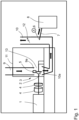
- the single figure schematically shows an embodiment of a device for detecting and measuring brake dust particles, which is intended as an integral component of a brake test bench.
- the brake test bench is designed as a flywheel brake test bench and is shown in the figure in a schematic view.
- a motor 1 e.g. an electric motor, serving as a prime mover, drives a brake disc 2 inserted in the brake test bench, which is part of the brake 3 to be tested.
- flywheel masses 4 can be integrated in a known manner.
- the brake disc 2 is partially enclosed in a known manner by a brake caliper 5, which also belongs to the brake 3 to be tested.
- the brake caliper 5 supports the brake pads (not shown in the figure), which are subject to wear when the brake 3 is applied, causing the (fine) particles to be detected to be released from the brake pads.
- Brake 3 is installed in the brake test bench in a brake mount (not shown), which supports the brake and its components and ensures stable support of the braking torque.
- a brake mount (not shown), which supports the brake and its components and ensures stable support of the braking torque.
- the design of such a brake mount in brake test benches is well known, so further description is unnecessary.
- a blower system comprising an air supply duct 9 with an outlet opening 9a and an exhaust duct 10 with an inlet opening 10a.
- the air supply duct 9 directs air through its outlet opening 9a into a housing 11 that encloses the brake 3 serving as the test specimen and is impermeable to brake dust particles.
- the exhaust duct 10 discharges this air from the housing 11 through its inlet opening 10a.
- the housing 11 thus encloses a brake receiving chamber 13.
- a measuring point for air volume flow measurement is provided in the exhaust air duct 10, e.g. at reference number 12.
- the fan system is usually present on brake test benches to ensure good ventilation of the brake, especially for cooling purposes.
- the air supplied via the supply air duct 9 can be conditioned in the desired manner with regard to temperature, humidity and purity (e.g. by means of a filter) by an air conditioning device (not shown) in order to achieve reproducible test results.
- the brake dust or brake dust particles are guided via the exhaust air duct 10 to the actual measuring point (at A), which is located in the exhaust air duct 10 and at which the sampling device 6 is provided. There, the particles are collected and guided, for example, via a heated hose 7 to the particle measuring device 8.
- the particle measuring device 8 can be a known device This could be a type of particle size analyzer, such as that used in exhaust gas measurement.
- the particle size analyzer 8 measures the number and size of particles.
Landscapes
- Chemical & Material Sciences (AREA)
- General Physics & Mathematics (AREA)
- Dispersion Chemistry (AREA)
- Health & Medical Sciences (AREA)
- Life Sciences & Earth Sciences (AREA)
- Analytical Chemistry (AREA)
- Biochemistry (AREA)
- Physics & Mathematics (AREA)
- Immunology (AREA)
- General Health & Medical Sciences (AREA)
- Pathology (AREA)
- Engineering & Computer Science (AREA)
- Transportation (AREA)
- Mechanical Engineering (AREA)
- Sampling And Sample Adjustment (AREA)
- Braking Arrangements (AREA)
Claims (12)
- Dispositif pour mesurer et capter des particules de poussière de frein, comprenant- une enceinte (11) pour définir un espace de réception de frein (13) dans lequel un frein (3) à contrôler peut être monté ;- une soufflerie comprenant un conduit d'air entrant (9) et un conduit d'air d'échappement (10) qui sont reliés chacun à l'espace de réception de frein (13) pour mener un flux d'air à travers l'espace de réception de frein (13) ;- un équipement de prélèvement (6) disposé dans le conduit d'air d'échappement (10) pour recevoir des particules de poussière de frein en un point de mesure (A) ;- un équipement de mesure de particules (8) pour mesurer le nombre et/ou la taille des particules de poussière de frein ; et comprenant- un équipement de convoyage (7) pour mener et convoyer les particules de poussière de frein de l'équipement de prélèvement (6) à l'équipement de mesure de particules (8) ; dans lequel- le conduit d'air entrant (9) présente une ouverture de sortie (9a) par laquelle de l'air peut être amené dans l'enceinte (11) ;- l'enceinte (11) est imperméable aux particules de poussière de frein ;- l'ouverture de sortie (9a) du conduit d'air entrant (9) prévue sur l'enceinte (11) et une ouverture d'admission (10a) du conduit d'air d'échappement (10) prévue sur l'enceinte (11) sont disposées l'une en face de l'autre ; caractérisé en ce que- la longueur du chemin d'écoulement du flux d'air et ainsi la distance entre l'axe de rotation du frein (3) et l'équipement de prélèvement (6) dépendent de la taille de la section transversale du conduit d'air d'échappement (10) ;- le conduit d'air d'échappement (10) est constitué d'un matériau non corrosif et électriquement conducteur ;- le conduit d'air d'échappement (10) est dimensionné de telle manière que son diamètre libre en son ouverture d'admission (10a) sur l'enceinte (11) ne soit pas inférieur à 70 % du diamètre du disque de frein à contrôler ; et dans lequel- la distance entre l'axe de rotation du frein (3) à contrôler et le point de mesure (A) est égale à 10 à 20 fois le diamètre du conduit d'air d'échappement (10).
- Dispositif selon la revendication 1, comprenant un logement de frein disposé dans l'espace de réception de frein (13) pour recevoir un frein (3).
- Dispositif selon la revendication 1 ou 2, dans lequel l'équipement de prélèvement (6) est disposé dans le conduit d'air d'échappement (10) de telle manière qu'un chemin d'écoulement du flux d'air du frein (3) jusqu'à l'équipement de prélèvement (6) présente une longueur prédéfinie.
- Dispositif selon l'une des revendications précédentes, dans lequel la distance entre l'ouverture d'admission (10a) du conduit d'air d'échappement (10) et l'équipement de prélèvement (6) correspond à 5 fois au moins le diamètre ou les plus grandes diagonales de la section transversale du conduit d'air d'échappement (10), en particulier à 10 fois au moins, en particulier à 20 fois au moins.
- Dispositif selon l'une des revendications précédentes, dans lequel le logement de frein est enfermé par un boîtier de mesure formant l'enceinte (11), ce qui permet de définir ainsi l'espace de réception de frein (13).
- Dispositif selon l'une des revendications précédentes, dans lequel- l'équipement de prélèvement (6) présente un point de prélèvement (A) dans le conduit d'air d'échappement (10) de la soufflerie ; et dans lequel- le point de prélèvement (A) est relié à l'équipement de mesure de particules (8) par l'intermédiaire de l'équipement de convoyage (7).
- Dispositif selon l'une des revendications précédentes, dans lequel, outre la mesure des particules de poussière de frein, l'équipement de mesure de particules (8) est également adapté à l'analyse des gaz d'échappement, en particulier à la mesure de particules dans des gaz d'échappement diesel.
- Dispositif selon l'une des revendications précédentes, dans lequel l'équipement de convoyage présente une conduite tubulaire ou flexible (7).
- Dispositif selon la revendication 8, dans lequel la conduite (7) relie l'équipement de prélèvement (6) à l'équipement de mesure de particules (8).
- Banc d'essai de freins, comprenant- un logement de frein pour recevoir un frein (3) à contrôler ;- un dispositif d'entraînement (1) pour appliquer une charge de freinage sur le frein (3) ;- des équipements de mesure pour acquérir des paramètres de contrôle et de mesure du frein ; et comprenant- un dispositif pour mesurer et capter des particules de poussière de frein selon l'une des revendications précédentes.
- Banc d'essai de freins selon la revendication 10, dans lequel le dispositif pour mesurer et capter des particules de poussière de frein fait partie intégrante du banc d'essai de freins.
- Banc d'essai de freins selon la revendication 10 ou 11, dans lequel les résultats de mesure de l'équipement de mesure de particules (8) et les paramètres de contrôle et de mesure du frein peuvent être corrélés les uns avec les autres.
Applications Claiming Priority (2)
| Application Number | Priority Date | Filing Date | Title |
|---|---|---|---|
| DE102017109356.7A DE102017109356A1 (de) | 2017-05-02 | 2017-05-02 | Vorrichtung zum Erfassen und Messen von Bremsstaub |
| PCT/EP2018/059801 WO2018202421A1 (fr) | 2017-05-02 | 2018-04-17 | Dispositif pour détecter et mesurer la poussière de frein |
Publications (2)
| Publication Number | Publication Date |
|---|---|
| EP3619083A1 EP3619083A1 (fr) | 2020-03-11 |
| EP3619083B1 true EP3619083B1 (fr) | 2025-05-21 |
Family
ID=62067583
Family Applications (1)
| Application Number | Title | Priority Date | Filing Date |
|---|---|---|---|
| EP18720761.8A Active EP3619083B1 (fr) | 2017-05-02 | 2018-04-17 | Dispositif pour enregistrer et mesurer la poussière des freins |
Country Status (6)
| Country | Link |
|---|---|
| US (1) | US20200150016A1 (fr) |
| EP (1) | EP3619083B1 (fr) |
| JP (1) | JP6720423B2 (fr) |
| CN (1) | CN110914123B (fr) |
| DE (1) | DE102017109356A1 (fr) |
| WO (1) | WO2018202421A1 (fr) |
Families Citing this family (25)
| Publication number | Priority date | Publication date | Assignee | Title |
|---|---|---|---|---|
| DE102017109356A1 (de) | 2017-05-02 | 2018-11-08 | Horiba Europe Gmbh | Vorrichtung zum Erfassen und Messen von Bremsstaub |
| IT201800008055A1 (it) * | 2018-08-10 | 2020-02-10 | Freni Brembo Spa | Metodo e dispositivo per rilevare e fornire informazioni di valutazione di frenata, indicative di un’emissione di particolato dovuta all’uso di un sistema frenante di un veicolo |
| DE102018120362A1 (de) * | 2018-08-21 | 2020-02-27 | Horiba Europe Gmbh | Partikelmesssystem mit einer Verdünnungsvorrichtung und Verfahren zur Partikelmessung |
| AT522936B1 (de) * | 2019-08-28 | 2021-05-15 | Avl List Gmbh | Messfelge zum Messen des Bremsabriebs einer Radbremse |
| FR3100506B1 (fr) | 2019-09-09 | 2021-08-06 | Psa Automobiles Sa | Installation de mesure de particules générées par un dispositif de freinage pendant des freinages |
| CN112229767B (zh) * | 2020-09-22 | 2024-08-20 | 中国科学院合肥物质科学研究院 | 一种测量颗粒物质振动的实验装置及方法 |
| CN112557071B (zh) * | 2020-11-05 | 2022-11-15 | 太原理工大学 | 一种气动力粉尘发生装置 |
| CN112525569B (zh) * | 2020-11-05 | 2022-11-11 | 太原理工大学 | 一种限定空间粉尘实验的电磁感应送尘测试装置及应用方法 |
| US12553802B2 (en) * | 2020-12-14 | 2026-02-17 | Horiba. Ltd. | Measurement method, and brake dust measurement program instructions |
| JP7723685B2 (ja) * | 2020-12-14 | 2025-08-14 | 株式会社堀場製作所 | ブレーキダスト測定装置及びブレーキダスト測定方法 |
| AT524701B1 (de) * | 2021-01-29 | 2022-10-15 | Avl List Gmbh | Messfelge zum Sammeln von Bremsabrieb |
| DE102021214127A1 (de) * | 2021-12-10 | 2023-06-15 | Zf Friedrichshafen Ag | Bremsenprüfstand und Prüfstandsystem |
| IT202100032402A1 (it) * | 2021-12-23 | 2023-06-23 | Brembo Spa | Metodo e sistema di rilevazione e fornitura di informazioni rappresentative di emissioni di particolato dovuta all’uso di un sistema frenante di un veicolo |
| CN114414269B (zh) * | 2022-03-30 | 2022-06-17 | 江苏天鑫机械科技有限公司 | 一种推土机驾驶室抗沙测试台架 |
| CN114964810A (zh) * | 2022-05-25 | 2022-08-30 | 中汽研汽车检验中心(天津)有限公司 | 一种用于车辆制动测试的环境模拟采样系统 |
| CN114993698A (zh) * | 2022-05-25 | 2022-09-02 | 中汽研汽车检验中心(天津)有限公司 | 制动系统磨损颗粒物排放测试系统 |
| CN114993697A (zh) * | 2022-05-25 | 2022-09-02 | 中汽研汽车检验中心(天津)有限公司 | 车辆制动系统磨损颗粒物排放测试系统 |
| AT526050B1 (de) | 2022-10-21 | 2023-11-15 | Avl List Gmbh | Vorrichtung zum Messen von Bremsemissionen |
| PL442856A1 (pl) * | 2022-11-17 | 2024-05-20 | Politechnika Gdańska | Komora do badania cząstek zużycia emitowanych z pary ciernej |
| PL442857A1 (pl) * | 2022-11-17 | 2024-05-20 | Politechnika Gdańska | Komora do badania cząstek zużycia emitowanych z pary ciernej |
| DE102023107451A1 (de) | 2023-03-24 | 2024-09-26 | Dr. Ing. H.C. F. Porsche Aktiengesellschaft | Messvorrichtung zum Messen von Bremsabriebspartikeln und Verfahren zum Messen von Bremsabriebspartikeln |
| WO2024262051A1 (fr) | 2023-06-23 | 2024-12-26 | 公益財団法人鉄道総合技術研究所 | Dispositif de collecte, système de mesure, procédé de collecte et procédé de mesure de matériau particulaire |
| CN117191421B (zh) * | 2023-08-29 | 2024-07-12 | 中汽研汽车检验中心(天津)有限公司 | 用于制动磨损颗粒物排放测试的装置和方法 |
| FR3153578B1 (fr) * | 2023-09-28 | 2025-09-05 | Tallano Tech | Procede de surveillance d’un taux de particules emises par une unite de frein, et systeme associe |
| US20250327497A1 (en) * | 2024-04-23 | 2025-10-23 | Horiba Instruments Incorporated | Systems and methods for brake-emissions testing |
Family Cites Families (14)
| Publication number | Priority date | Publication date | Assignee | Title |
|---|---|---|---|---|
| DE20308576U1 (de) * | 2003-05-30 | 2003-12-18 | Cramer Von Clausbruch, Dirk | Vorrichtung für eine Scheibenbremse als Radbremse bei einem Personenkraftwagen oder einem Nutzfahrzeug |
| DE10329961A1 (de) * | 2003-07-03 | 2005-01-27 | EL-Waraki, M. Sami, Dipl.-Ing. | Integrierte Feinstaubabsaugvorrichtung für Fahrzeuge |
| DE202005006844U1 (de) * | 2005-04-27 | 2005-07-07 | Bost, Bernd | Vorrichtung zum Auffangen des Abriebs der Reibblöcke aus Bremsanlagen von Kraftfahrzeugen |
| DE102006051972A1 (de) * | 2006-11-03 | 2008-05-08 | Konstantinos Tsiberidis | Bremsstaubsammelvorrichtung |
| DE102007009744A1 (de) * | 2007-02-28 | 2008-09-04 | Continental Automotive Gmbh | Abtransport von Bremsstaub |
| DE102009032835B4 (de) * | 2009-07-13 | 2014-12-18 | Mann + Hummel Gmbh | Vorrichtung für die Entlüftung von Kurbelgehäusegasen |
| DE102012002628A1 (de) * | 2012-02-10 | 2012-09-20 | Daimler Ag | Kraftfahrzeugbremse |
| JP5912981B2 (ja) * | 2012-08-06 | 2016-04-27 | 株式会社堀場製作所 | 排ガス希釈装置及びpm測定システム |
| DE102012016836B4 (de) * | 2012-08-27 | 2022-05-19 | Mann+Hummel Gmbh | Bremsstaubaufnahmevorrichtung für Kraftfahrzeuge |
| US9688194B2 (en) * | 2015-03-26 | 2017-06-27 | Ford Global Technologies, Llc | In-vehicle particulate sensor data analysis |
| CN106525520B (zh) * | 2015-09-15 | 2020-04-21 | 农业农村部规划设计研究院 | 固定燃烧源烟气混合通道稀释多级采样装置 |
| FR3042597B1 (fr) * | 2015-10-16 | 2021-03-19 | Planetwatch24 | Dispositif et procede de capture et d'enregistrement des particules fines et/ou densite des gaz nox dans l'air |
| WO2017097901A1 (fr) | 2015-12-09 | 2017-06-15 | Horiba Europe Gmbh | Dispositif pour détecter et mesurer la poussière de frein |
| DE102017109356A1 (de) | 2017-05-02 | 2018-11-08 | Horiba Europe Gmbh | Vorrichtung zum Erfassen und Messen von Bremsstaub |
-
2017
- 2017-05-02 DE DE102017109356.7A patent/DE102017109356A1/de active Pending
-
2018
- 2018-04-17 EP EP18720761.8A patent/EP3619083B1/fr active Active
- 2018-04-17 JP JP2019560117A patent/JP6720423B2/ja active Active
- 2018-04-17 US US16/609,588 patent/US20200150016A1/en not_active Abandoned
- 2018-04-17 WO PCT/EP2018/059801 patent/WO2018202421A1/fr not_active Ceased
- 2018-04-17 CN CN201880022475.7A patent/CN110914123B/zh active Active
Non-Patent Citations (5)
| Title |
|---|
| CARSTEN TRAUTMANN: "Erstellen eines Messprozesses zur Partikelmessung von Bremsstaub", 2 October 2013, TECHNISCHE UNIVERSITÄT ILMENAU * |
| H. SACHSE, K. AUGSBURG: "XXXIV Internationales [My]- Symposium Bremsen-Fachtagung : October 30th to 31st 2015, Bad Neuenahr, Germany", 31 October 2015, ISBN: 9783183794126 * |
| HAGINO HIROYUKI ET AL: "Laboratory testing of airborne brake wear particle emissions using a dynamometer system under urban city driving cycles", ATMOSPHERIC ENVIRONMENT, PERGAMON, GB, vol. 131, 12 February 2016 (2016-02-12), pages 269 - 278, XP029455940, ISSN: 1352-2310, DOI: 10.1016/J.ATMOSENV.2016.02.014 * |
| KLAUS AUGSBURG: "Sampling of Brake Dust Particles", 15 June 2016 (2016-06-15), Retrieved from the Internet <URL:http://2016.eurobrake.net/> [retrieved on 20201002] * |
| S. GRAMSTAT, A CSERHATI, M. SCHROEDER, DMYTRO LUGOVYY: "Brake Particle Emission Measurements - Testing Method and results", 28 March 2017 (2017-03-28), Retrieved from the Internet <URL:http://2016.eurobrake.net/> [retrieved on 20201002] * |
Also Published As
| Publication number | Publication date |
|---|---|
| EP3619083A1 (fr) | 2020-03-11 |
| CN110914123B (zh) | 2023-07-04 |
| JP2020520448A (ja) | 2020-07-09 |
| JP6720423B2 (ja) | 2020-07-08 |
| WO2018202421A1 (fr) | 2018-11-08 |
| CN110914123A (zh) | 2020-03-24 |
| DE102017109356A1 (de) | 2018-11-08 |
| US20200150016A1 (en) | 2020-05-14 |
Similar Documents
| Publication | Publication Date | Title |
|---|---|---|
| EP3619083B1 (fr) | Dispositif pour enregistrer et mesurer la poussière des freins | |
| WO2017097901A1 (fr) | Dispositif pour détecter et mesurer la poussière de frein | |
| EP2270465B2 (fr) | Procédé et dispositif pour la détection, caractérisation et/ou élimination de particules | |
| DE112009002558T5 (de) | Partikelprobenentnahmesystem und Verfahren zum Verringern einer Überentnahme während Übergängen | |
| DE602004004688T2 (de) | Aktive Steuerung der Temperatur eines Filters | |
| DE102014222786B4 (de) | Verfahren und Vorrichtung zur Dichtigkeitsprüfung von elektrochemischen Speichern in Form von Batterien oder Batterieeinzelzellen | |
| EP2051055A2 (fr) | Dispositif d'examen d'un disque de frein sous influence du sel, de l'humidité et du froid | |
| DE112014000290T5 (de) | Akustik-Messvorrichtung | |
| EP1923694B1 (fr) | Methode et dispositif pour déterminer la quantité d'huile dans un flux de gaz | |
| DE102010046597A1 (de) | Lagerprüfstand zur Durchführung von Messsungen an einem Abgasturboladerlager und ein Verfahren zur Vermessung eines Abgasturboladerlagers mit Hilfe des Lagerprüfstandes | |
| AT527039B1 (de) | Verfahren zum Durchführen eines Lecktests in einer Messanordnung | |
| DE102010038897A1 (de) | Streulichtmessverfahren | |
| WO2019120820A1 (fr) | Système pour vérifier des appareils aérosols et de mesure de flux | |
| CN206146647U (zh) | 一种汽车尾气流量测量控制系统 | |
| Sanuddin et al. | Airflow Simulation and Measurement of Brake Wear Particle Emissions with a Novel Test Rig | |
| DE102021211155B3 (de) | Versuchsvorrichtung für ein Fahrzeugbremsenuntersuchungssystem, Fahrzeugbremsenuntersuchungssystem zum Messen und Erfassen von Bremsstaub-Partikeln, Verfahren zum Messen und Erfassen von Bremsstaub-Partikeln bei einem Fahrzeug | |
| WO2016023878A1 (fr) | Banc d'essai avec dispositif d'alimentation en gaz de refroidissement | |
| EP4050319B1 (fr) | Dispositif et procédé de prélèvement isocinétique d'un échantillon à partir d'un aérosol en écoulement | |
| DE102012211538B4 (de) | Verfahren und System zum Nachweisen von in einem Aerosol schwebenden Kohlenstoffnanoröhren | |
| DE202008013327U1 (de) | Aerosolquellsystem mit Aerosolausströmern für eine gleichmäßige Verteilung von Aerosol eines Aerosolgenerators zu Prüfzwecken in die Umgebung | |
| AT526050B1 (de) | Vorrichtung zum Messen von Bremsemissionen | |
| Sanuddin et al. | Measurement of brake wear particle emissions with a novel test rig | |
| AT525576B1 (de) | Vorrichtung und Verfahren zur Abgasmessung an einem Prüfling | |
| EP3387396A1 (fr) | Dispositif pour système de mesure laser | |
| DE102004046529A1 (de) | Verfahren zur Ermittlung einer Geschwindigkeitsverteilung einer Gasströmung |
Legal Events
| Date | Code | Title | Description |
|---|---|---|---|
| STAA | Information on the status of an ep patent application or granted ep patent |
Free format text: STATUS: UNKNOWN |
|
| STAA | Information on the status of an ep patent application or granted ep patent |
Free format text: STATUS: THE INTERNATIONAL PUBLICATION HAS BEEN MADE |
|
| PUAI | Public reference made under article 153(3) epc to a published international application that has entered the european phase |
Free format text: ORIGINAL CODE: 0009012 |
|
| STAA | Information on the status of an ep patent application or granted ep patent |
Free format text: STATUS: REQUEST FOR EXAMINATION WAS MADE |
|
| 17P | Request for examination filed |
Effective date: 20190607 |
|
| AK | Designated contracting states |
Kind code of ref document: A1 Designated state(s): AL AT BE BG CH CY CZ DE DK EE ES FI FR GB GR HR HU IE IS IT LI LT LU LV MC MK MT NL NO PL PT RO RS SE SI SK SM TR |
|
| AX | Request for extension of the european patent |
Extension state: BA ME |
|
| TPAC | Observations filed by third parties |
Free format text: ORIGINAL CODE: EPIDOSNTIPA |
|
| DAV | Request for validation of the european patent (deleted) | ||
| DAX | Request for extension of the european patent (deleted) | ||
| STAA | Information on the status of an ep patent application or granted ep patent |
Free format text: STATUS: EXAMINATION IS IN PROGRESS |
|
| 17Q | First examination report despatched |
Effective date: 20201027 |
|
| TPAC | Observations filed by third parties |
Free format text: ORIGINAL CODE: EPIDOSNTIPA |
|
| GRAP | Despatch of communication of intention to grant a patent |
Free format text: ORIGINAL CODE: EPIDOSNIGR1 |
|
| STAA | Information on the status of an ep patent application or granted ep patent |
Free format text: STATUS: GRANT OF PATENT IS INTENDED |
|
| TPAC | Observations filed by third parties |
Free format text: ORIGINAL CODE: EPIDOSNTIPA |
|
| INTG | Intention to grant announced |
Effective date: 20211202 |
|
| GRAJ | Information related to disapproval of communication of intention to grant by the applicant or resumption of examination proceedings by the epo deleted |
Free format text: ORIGINAL CODE: EPIDOSDIGR1 |
|
| STAA | Information on the status of an ep patent application or granted ep patent |
Free format text: STATUS: EXAMINATION IS IN PROGRESS |
|
| INTC | Intention to grant announced (deleted) | ||
| TPAC | Observations filed by third parties |
Free format text: ORIGINAL CODE: EPIDOSNTIPA |
|
| TPAC | Observations filed by third parties |
Free format text: ORIGINAL CODE: EPIDOSNTIPA |
|
| TPAC | Observations filed by third parties |
Free format text: ORIGINAL CODE: EPIDOSNTIPA |
|
| GRAP | Despatch of communication of intention to grant a patent |
Free format text: ORIGINAL CODE: EPIDOSNIGR1 |
|
| STAA | Information on the status of an ep patent application or granted ep patent |
Free format text: STATUS: GRANT OF PATENT IS INTENDED |
|
| INTG | Intention to grant announced |
Effective date: 20241112 |
|
| GRAS | Grant fee paid |
Free format text: ORIGINAL CODE: EPIDOSNIGR3 |
|
| GRAA | (expected) grant |
Free format text: ORIGINAL CODE: 0009210 |
|
| STAA | Information on the status of an ep patent application or granted ep patent |
Free format text: STATUS: THE PATENT HAS BEEN GRANTED |
|
| AK | Designated contracting states |
Kind code of ref document: B1 Designated state(s): AL AT BE BG CH CY CZ DE DK EE ES FI FR GB GR HR HU IE IS IT LI LT LU LV MC MK MT NL NO PL PT RO RS SE SI SK SM TR |
|
| REG | Reference to a national code |
Ref country code: GB Ref legal event code: FG4D Free format text: NOT ENGLISH |
|
| REG | Reference to a national code |
Ref country code: CH Ref legal event code: EP |
|
| REG | Reference to a national code |
Ref country code: DE Ref legal event code: R096 Ref document number: 502018015828 Country of ref document: DE |
|
| REG | Reference to a national code |
Ref country code: IE Ref legal event code: FG4D Free format text: LANGUAGE OF EP DOCUMENT: GERMAN |
|
| REG | Reference to a national code |
Ref country code: DE Ref legal event code: R081 Ref document number: 502018015828 Country of ref document: DE Owner name: HORIBA EUROPE GMBH, ZWEIGNIEDERLASSUNG DARMSTA, DE Free format text: FORMER OWNER: HORIBA EUROPE GMBH, ZWEIGNIEDERLASSUNG DARMSTADT, 64293 DARMSTADT, DE Ref country code: DE Ref legal event code: R081 Ref document number: 502018015828 Country of ref document: DE Owner name: AUDI AKTIENGESELLSCHAFT, DE Free format text: FORMER OWNER: HORIBA EUROPE GMBH, ZWEIGNIEDERLASSUNG DARMSTADT, 64293 DARMSTADT, DE |
|
| REG | Reference to a national code |
Ref country code: DE Ref legal event code: R081 Ref document number: 502018015828 Country of ref document: DE Owner name: HORIBA EUROPE GMBH, ZWEIGNIEDERLASSUNG DARMSTA, DE Free format text: FORMER OWNERS: AUDI AKTIENGESELLSCHAFT, 85057 INGOLSTADT, DE; HORIBA EUROPE GMBH, ZWEIGNIEDERLASSUNG DARMSTADT, 64293 DARMSTADT, DE |
|
| REG | Reference to a national code |
Ref country code: NL Ref legal event code: MP Effective date: 20250521 |
|
| PG25 | Lapsed in a contracting state [announced via postgrant information from national office to epo] |
Ref country code: PT Free format text: LAPSE BECAUSE OF FAILURE TO SUBMIT A TRANSLATION OF THE DESCRIPTION OR TO PAY THE FEE WITHIN THE PRESCRIBED TIME-LIMIT Effective date: 20250922 Ref country code: ES Free format text: LAPSE BECAUSE OF FAILURE TO SUBMIT A TRANSLATION OF THE DESCRIPTION OR TO PAY THE FEE WITHIN THE PRESCRIBED TIME-LIMIT Effective date: 20250521 Ref country code: FI Free format text: LAPSE BECAUSE OF FAILURE TO SUBMIT A TRANSLATION OF THE DESCRIPTION OR TO PAY THE FEE WITHIN THE PRESCRIBED TIME-LIMIT Effective date: 20250521 |
|
| REG | Reference to a national code |
Ref country code: LT Ref legal event code: MG9D |
|
| PG25 | Lapsed in a contracting state [announced via postgrant information from national office to epo] |
Ref country code: NO Free format text: LAPSE BECAUSE OF FAILURE TO SUBMIT A TRANSLATION OF THE DESCRIPTION OR TO PAY THE FEE WITHIN THE PRESCRIBED TIME-LIMIT Effective date: 20250821 Ref country code: GR Free format text: LAPSE BECAUSE OF FAILURE TO SUBMIT A TRANSLATION OF THE DESCRIPTION OR TO PAY THE FEE WITHIN THE PRESCRIBED TIME-LIMIT Effective date: 20250822 |
|
| PG25 | Lapsed in a contracting state [announced via postgrant information from national office to epo] |
Ref country code: PL Free format text: LAPSE BECAUSE OF FAILURE TO SUBMIT A TRANSLATION OF THE DESCRIPTION OR TO PAY THE FEE WITHIN THE PRESCRIBED TIME-LIMIT Effective date: 20250521 Ref country code: NL Free format text: LAPSE BECAUSE OF FAILURE TO SUBMIT A TRANSLATION OF THE DESCRIPTION OR TO PAY THE FEE WITHIN THE PRESCRIBED TIME-LIMIT Effective date: 20250521 |
|
| PG25 | Lapsed in a contracting state [announced via postgrant information from national office to epo] |
Ref country code: BG Free format text: LAPSE BECAUSE OF FAILURE TO SUBMIT A TRANSLATION OF THE DESCRIPTION OR TO PAY THE FEE WITHIN THE PRESCRIBED TIME-LIMIT Effective date: 20250521 |
|
| PG25 | Lapsed in a contracting state [announced via postgrant information from national office to epo] |
Ref country code: HR Free format text: LAPSE BECAUSE OF FAILURE TO SUBMIT A TRANSLATION OF THE DESCRIPTION OR TO PAY THE FEE WITHIN THE PRESCRIBED TIME-LIMIT Effective date: 20250521 |
|
| PG25 | Lapsed in a contracting state [announced via postgrant information from national office to epo] |
Ref country code: RS Free format text: LAPSE BECAUSE OF FAILURE TO SUBMIT A TRANSLATION OF THE DESCRIPTION OR TO PAY THE FEE WITHIN THE PRESCRIBED TIME-LIMIT Effective date: 20250821 |
|
| PG25 | Lapsed in a contracting state [announced via postgrant information from national office to epo] |
Ref country code: IS Free format text: LAPSE BECAUSE OF FAILURE TO SUBMIT A TRANSLATION OF THE DESCRIPTION OR TO PAY THE FEE WITHIN THE PRESCRIBED TIME-LIMIT Effective date: 20250921 |
|
| PG25 | Lapsed in a contracting state [announced via postgrant information from national office to epo] |
Ref country code: LV Free format text: LAPSE BECAUSE OF FAILURE TO SUBMIT A TRANSLATION OF THE DESCRIPTION OR TO PAY THE FEE WITHIN THE PRESCRIBED TIME-LIMIT Effective date: 20250521 |
|
| PG25 | Lapsed in a contracting state [announced via postgrant information from national office to epo] |
Ref country code: DK Free format text: LAPSE BECAUSE OF FAILURE TO SUBMIT A TRANSLATION OF THE DESCRIPTION OR TO PAY THE FEE WITHIN THE PRESCRIBED TIME-LIMIT Effective date: 20250521 Ref country code: SM Free format text: LAPSE BECAUSE OF FAILURE TO SUBMIT A TRANSLATION OF THE DESCRIPTION OR TO PAY THE FEE WITHIN THE PRESCRIBED TIME-LIMIT Effective date: 20250521 |
|
| PG25 | Lapsed in a contracting state [announced via postgrant information from national office to epo] |
Ref country code: CZ Free format text: LAPSE BECAUSE OF FAILURE TO SUBMIT A TRANSLATION OF THE DESCRIPTION OR TO PAY THE FEE WITHIN THE PRESCRIBED TIME-LIMIT Effective date: 20250521 |
|
| PG25 | Lapsed in a contracting state [announced via postgrant information from national office to epo] |
Ref country code: EE Free format text: LAPSE BECAUSE OF FAILURE TO SUBMIT A TRANSLATION OF THE DESCRIPTION OR TO PAY THE FEE WITHIN THE PRESCRIBED TIME-LIMIT Effective date: 20250521 |
|
| PG25 | Lapsed in a contracting state [announced via postgrant information from national office to epo] |
Ref country code: RO Free format text: LAPSE BECAUSE OF FAILURE TO SUBMIT A TRANSLATION OF THE DESCRIPTION OR TO PAY THE FEE WITHIN THE PRESCRIBED TIME-LIMIT Effective date: 20250521 Ref country code: SK Free format text: LAPSE BECAUSE OF FAILURE TO SUBMIT A TRANSLATION OF THE DESCRIPTION OR TO PAY THE FEE WITHIN THE PRESCRIBED TIME-LIMIT Effective date: 20250521 |
|
| PG25 | Lapsed in a contracting state [announced via postgrant information from national office to epo] |
Ref country code: IT Free format text: LAPSE BECAUSE OF FAILURE TO SUBMIT A TRANSLATION OF THE DESCRIPTION OR TO PAY THE FEE WITHIN THE PRESCRIBED TIME-LIMIT Effective date: 20250521 |
|
| REG | Reference to a national code |
Ref country code: DE Ref legal event code: R097 Ref document number: 502018015828 Country of ref document: DE |
|
| PLBE | No opposition filed within time limit |
Free format text: ORIGINAL CODE: 0009261 |
|
| STAA | Information on the status of an ep patent application or granted ep patent |
Free format text: STATUS: NO OPPOSITION FILED WITHIN TIME LIMIT |
|
| REG | Reference to a national code |
Ref country code: CH Ref legal event code: L10 Free format text: ST27 STATUS EVENT CODE: U-0-0-L10-L00 (AS PROVIDED BY THE NATIONAL OFFICE) Effective date: 20260402 |
|
| 26N | No opposition filed |
Effective date: 20260224 |