EP3619155B1 - Ensemble actionneur de bras pour grue - Google Patents
Ensemble actionneur de bras pour grue Download PDFInfo
- Publication number
- EP3619155B1 EP3619155B1 EP18793885.7A EP18793885A EP3619155B1 EP 3619155 B1 EP3619155 B1 EP 3619155B1 EP 18793885 A EP18793885 A EP 18793885A EP 3619155 B1 EP3619155 B1 EP 3619155B1
- Authority
- EP
- European Patent Office
- Prior art keywords
- arm
- crane
- actuator assembly
- main arm
- main
- Prior art date
- Legal status (The legal status is an assumption and is not a legal conclusion. Google has not performed a legal analysis and makes no representation as to the accuracy of the status listed.)
- Active
Links
Images



Classifications
-
- B—PERFORMING OPERATIONS; TRANSPORTING
- B66—HOISTING; LIFTING; HAULING
- B66C—CRANES; LOAD-ENGAGING ELEMENTS OR DEVICES FOR CRANES, CAPSTANS, WINCHES, OR TACKLES
- B66C23/00—Cranes comprising essentially a beam, boom, or triangular structure acting as a cantilever and mounted for translatory of swinging movements in vertical or horizontal planes or a combination of such movements, e.g. jib-cranes, derricks, tower cranes
- B66C23/62—Constructional features or details
- B66C23/82—Luffing gear
-
- B—PERFORMING OPERATIONS; TRANSPORTING
- B66—HOISTING; LIFTING; HAULING
- B66C—CRANES; LOAD-ENGAGING ELEMENTS OR DEVICES FOR CRANES, CAPSTANS, WINCHES, OR TACKLES
- B66C23/00—Cranes comprising essentially a beam, boom, or triangular structure acting as a cantilever and mounted for translatory of swinging movements in vertical or horizontal planes or a combination of such movements, e.g. jib-cranes, derricks, tower cranes
-
- A—HUMAN NECESSITIES
- A63—SPORTS; GAMES; AMUSEMENTS
- A63H—TOYS, e.g. TOPS, DOLLS, HOOPS OR BUILDING BLOCKS
- A63H17/00—Toy vehicles, e.g. with self-drive; ; Cranes, winches or the like; Accessories therefor
- A63H17/12—Toy vehicles, e.g. with self-drive; ; Cranes, winches or the like; Accessories therefor with cranes, winches or the like
-
- B—PERFORMING OPERATIONS; TRANSPORTING
- B66—HOISTING; LIFTING; HAULING
- B66C—CRANES; LOAD-ENGAGING ELEMENTS OR DEVICES FOR CRANES, CAPSTANS, WINCHES, OR TACKLES
- B66C23/00—Cranes comprising essentially a beam, boom, or triangular structure acting as a cantilever and mounted for translatory of swinging movements in vertical or horizontal planes or a combination of such movements, e.g. jib-cranes, derricks, tower cranes
- B66C23/06—Cranes comprising essentially a beam, boom, or triangular structure acting as a cantilever and mounted for translatory of swinging movements in vertical or horizontal planes or a combination of such movements, e.g. jib-cranes, derricks, tower cranes with jibs mounted for jibbing or luffing movements
- B66C23/08—Cranes comprising essentially a beam, boom, or triangular structure acting as a cantilever and mounted for translatory of swinging movements in vertical or horizontal planes or a combination of such movements, e.g. jib-cranes, derricks, tower cranes with jibs mounted for jibbing or luffing movements and adapted to move the loads in predetermined paths
- B66C23/10—Cranes comprising essentially a beam, boom, or triangular structure acting as a cantilever and mounted for translatory of swinging movements in vertical or horizontal planes or a combination of such movements, e.g. jib-cranes, derricks, tower cranes with jibs mounted for jibbing or luffing movements and adapted to move the loads in predetermined paths the paths being substantially horizontal; Level-luffing jib-cranes
- B66C23/14—Cranes comprising essentially a beam, boom, or triangular structure acting as a cantilever and mounted for translatory of swinging movements in vertical or horizontal planes or a combination of such movements, e.g. jib-cranes, derricks, tower cranes with jibs mounted for jibbing or luffing movements and adapted to move the loads in predetermined paths the paths being substantially horizontal; Level-luffing jib-cranes with means, e.g. pantograph arrangements, for varying jib configuration
-
- B—PERFORMING OPERATIONS; TRANSPORTING
- B66—HOISTING; LIFTING; HAULING
- B66C—CRANES; LOAD-ENGAGING ELEMENTS OR DEVICES FOR CRANES, CAPSTANS, WINCHES, OR TACKLES
- B66C23/00—Cranes comprising essentially a beam, boom, or triangular structure acting as a cantilever and mounted for translatory of swinging movements in vertical or horizontal planes or a combination of such movements, e.g. jib-cranes, derricks, tower cranes
- B66C23/62—Constructional features or details
-
- B—PERFORMING OPERATIONS; TRANSPORTING
- B66—HOISTING; LIFTING; HAULING
- B66C—CRANES; LOAD-ENGAGING ELEMENTS OR DEVICES FOR CRANES, CAPSTANS, WINCHES, OR TACKLES
- B66C2700/00—Cranes
- B66C2700/03—Cranes with arms or jibs; Multiple cranes
-
- E—FIXED CONSTRUCTIONS
- E02—HYDRAULIC ENGINEERING; FOUNDATIONS; SOIL SHIFTING
- E02F—DREDGING; SOIL-SHIFTING
- E02F3/00—Dredgers; Soil-shifting machines
- E02F3/04—Dredgers; Soil-shifting machines mechanically-driven
- E02F3/28—Dredgers; Soil-shifting machines mechanically-driven with digging tools mounted on a dipper- or bucket-arm, i.e. there is either one arm or a pair of arms, e.g. dippers, buckets
- E02F3/34—Dredgers; Soil-shifting machines mechanically-driven with digging tools mounted on a dipper- or bucket-arm, i.e. there is either one arm or a pair of arms, e.g. dippers, buckets with bucket-arms, i.e. a pair of arms, e.g. manufacturing processes, form, geometry, material of bucket-arms directly pivoted on the frames of tractors or self-propelled machines
Definitions
- the present invention is related to an arm actuator assembly for a crane, according to the preamble of claim 1.
- the present invention is especially related to an arm actuator assembly for a crane, which can contribute to electrification and replace solutions of cranes where there are used hydraulic cylinders today.
- a slewing actuator system for horizontally rotating a boom structure by means of engagement with gearing means.
- the slewing actuator system comprises a rotatable cylindrical disc with exterior teeth that are in engagement with one or more fixed motor-driven (electrical) fearing means that impart rotational movement to cylindrical disc and thus the boom structure arranged thereto.
- CN205709609 U (BEIQI FONTON MOTOR CO LTD) describes a similar solution to US8123053 B2 where a crane boom is arranged to a rotatable disc.
- the main object of the present invention is to provide an arm actuator assembly for a crane partly or entirely solving the above-mentioned drawbacks of prior art.
- An object of the present invention is to provide an arm actuator assembly for a crane comprising at least one fixed cogwheel arranged in a parallel vertical plane of an arm of the crane and at least one arm drive pinion gear arranged to the arm and in engagement with the fixed cogwheel enabling elevation and lowering of the arm in the vertical plane by operation of the at least one arm drive pinion gear.
- An object of the present invention is to provide an arm actuator assembly for a crane which provides an environmentally friendly solution by that it does not use polluting fluids, such as hydraulic oil or similar, which can constitute a risk for the environment or personnel at breakdown or leakage.
- An arm actuator assembly for a crane is defined by the technical features of claim 1. Preferable features of the arm actuator assembly are disclosed in the dependent claims.
- Cranes comprise at least one main arm pivotally arranged to a support structure at a lower end thereof by means of a pivoting connection. Cranes further may comprise at least one elbow arm pivotally arranged to the upper end of the main arm, possibly via a connection link.
- the support structure of the crane is typically formed by a tower (pedestal) and a base platform, where the base platform, which the main arm of the crane are connected to, typically is arranged to the tower by means of a rotational interface (slew bearing), enabling the crane to rotate about the tower.
- the present invention provides an arm actuator assembly for a crane where the main components are at least one fixed cogwheel and at least one arm drive pinion gear.
- the arm actuator assembly comprises at least one cogwheel arranged in a parallel vertical plane of the main arm and fixed to the support structure with its horizontal center axis corresponding with horizontal center axis of the pivoting connection between the main arm and support structure.
- the arm actuator assembly further comprises at least one main arm drive pinion gear arranged to the main arm and in engagement with the at least one fixed cogwheel. Accordingly, in the first embodiment of the arm actuator assembly for a crane according to the present invention operation of the at least one main arm drive pinion gear in engagement with the at least one fixed cogwheel enable elevation or lowering of the main arm of the crane in the vertical plane.
- the at least one main arm drive pinion gear is preferably driven by at least one electric power source (motor). If desired or necessary there can be arranged a gear exchange between the electric power source and the main arm drive pinion gear.
- the at least one cogwheel exhibits a (considerably) larger diameter than the at least one main arm drive pinion gear.
- the present invention is preferably at least one main arm drive pinion gear arranged at lower side of the main arm.
- the arm actuator assembly for a crane works by that operation of the at least one electrical power source results in that the at least one main arm drive pinion gear travels along the exterior circumference of the fixed cogwheel and in engagement therewith, resulting in that the main arm is elevated or lowered in the vertical plane according to the rotational direction of the main arm drive pinion gear.
- the arm actuator assembly further comprises an upper elbow arm drive unit for an elbow arm arranged for operating an upper elbow arm of the crane.
- the elbow arm drive unit is arranged to the lower part of the main arm or the support structure for the crane.
- the elbow arm drive unit is formed by a torque arm pivotally arranged to lower part of the main arm and further comprising a tension arm extending between the upper elbow arm and torque arm, wherein the tension arm is pivotally arranged to the upper elbow arm and main arm, respectively.
- the torque arm is a single or double torque arm.
- the torque arm is arranged with to pivot about a horizontal centre axis of a main arm drive pinion gear arranged at rear part of the main arm.
- the arm actuator assembly for a crane works by that, as the main arm is elevated or lowered in the vertical plane as described above, the elbow arm will correspondingly move in the vertical plane due to the interaction of the tension arm.
- the elbow arm drive unit is formed by a tension winch, preferably an electrically driven winch, arranged to the support structure of the crane and a tension wire extending between the tension winch and rear part of the elbow arm, alternatively rear part of a connection link connecting the main arm and elbow arm.
- a tension winch preferably an electrically driven winch
- the elbow arm can be controlled both in correspondence with the movement of the main arm and separately.
- the arm actuator assembly for a crane provides a solution, which enables the crane to be driven by electrical power. Accordingly, there is no need for hydraulic cylinders for operation of the arms of the crane.
- sufficient power/moment of the arm actuator assembly for a crane according to the present invention can be achieved by utilizing several main arm drive pinion gears in engagement with the at least one fixed cogwheel. Further, the diameter of the cogwheel can also be designed to achieve sufficient power/moment of the arm actuator assembly according to the present invention.
- the arm actuator assembly according to the present invention removes the need for hydraulic reservoir, hydraulic pipes and hoses, as well as hydraulic pumps, which would provide free space at the deck of a marine vessel.
- the present invention would further provide a more rapid/force/power effective controlling of the crane, as the there are no intermediate means transferring the power/force to the crane arm, as the main arm drive pinion gears are directly connected to the main arm via the cogwheel.
- a great advantage with the present invention is that there are low requirements for maintenance due to few moveable and force transferring parts.
- the present invention further provides a solution which is less exposed to wear, compared to prior art, due to few parts for transferring forces and that there is no requirement for a sealed system as hydraulic systems.
- the present invention is mainly related to operation of the main arm by means of the fixed cogwheel and the main arm drive pinion gears
- the same principle can also be used for operation of the elbow arm in relation to the main arm by arranging a fixed cogwheel to upper end portion of the main arm, with its center in the pivoting connection between the main arm and the elbow arm, and further arrange at least one elbow arm drive pinion gear to the elbow arm.
- FIG. 1 is a principle drawing of a crane 100, in the form of a deck crane, according to prior art.
- the crane 100 has a support structure 101 formed by a base platform 102 rotatably arranged on upper end of a tower 103 (pedestal) via a rotational interface 104 (slew bearing), which is well known in prior art and needs no further description herein.
- the crane 100 further comprises a main arm 110 having a lower end pivotally mounted on the base platform 102 by means of a pivoting connection 105, e.g. formed by a shaft 106 and attachment lugs 107.
- the main arm 110 can be raised and lowered by actuation of at least one hydraulic cylinder 111 having its lower end arranged to the base platform 102 and upper end arranged to an intermediate location along the length of the main arm 110.
- the crane 100 also comprises an upper elbow arm 120 having a lower end pivotally arranged to the upper end portion of the main arm 110.
- the upper elbow arm 120 is pivotally connected relative to the main arm 110 by at least one hydraulic cylinder 121 having lower end portion pivotally arranged to an intermediate location along the main arm 110 and upper end portion pivotally arranged an intermediate location along the length of the upper elbow arm 120.
- Operation of the hydraulic cylinders 111 and 121 enables the crane 100 to be raised and lowered as well as to be extended and retracted, and the rotational interface 104 enables the crane 100 to be rotated about the tower 103.
- the crane 100 further includes a main load winch 130 mounted on the lower end portion of the main arm 110 or the base platform 102 to pay out or reel in a main load wire 131 which is wound about a spool 132.
- a hook 133 is attached to the distal end of the wire 131.
- the wire 131 extends over a guide sheave 134 mounted on the distal end of the main arm 110, a further guide sheave 135 mounted on the lower or proximal end of elbow arm 120, and a distal sheave 136 mounted on the distal end portion of the elbow arm 120.
- the present invention is related to an arm actuator assembly enabling such cranes, especially offshore/maritime cranes, to be operated without the use of hydraulic cylinders, at least minimizing the use of hydraulic cylinders for operation thereof.
- FIG. 2a-c is a principle drawing of a crane 100 provided with an arm actuator assembly 200 for a crane according to a first embodiment of the present invention.
- the crane 100 comprises as described above a support structure 101 comprising a base platform 102 rotatably arranged to a tower 103 by means of a rotational interface 104.
- the main arm 110 is pivotably arranged to the base platform 102 by that the base platform 102 is provided with a pivoting connection 105.
- the pivoting connection 105 can e.g.
- the longitudinal centre axis of the shaft 106 forms a pivoting centre axis which the main arm 110 pivots about.
- the present invention provides, as mentioned, an arm actuator assembly 200 which removes the need for hydraulic cylinders 111 and 121 for operation of the main arm 110 and/or elbow arm 120.
- the main component of the arm actuator assembly 200 according to the present invention is at least one cogwheel 210, wherein the at least one cogwheel 210, with its circumference, is arranged in a parallel vertical plane with the main arm 110 and fixed to the support structure 100, i.e. the base platform 102 with its horizontal center axis corresponding with the pivoting centre axis of the main arm 110, i.e. the horizontal center axis of the pivoting connection 105/shaft 106.
- the arm actuator assembly 200 further comprises at least one main arm drive pinion gear 220a-b arranged to the main arm 110 and in engagement with the fixed cogwheel 210.
- the at least one cogwheel 210 exhibits a (considerably) larger diameter than the at least one main arm drive pinion gear 220a-b.
- the arm actuator assembly 200 comprises a main arm drive pinion gear 220a, arranged to the main arm 110 at a distance from the lower end of the main arm 110 corresponding to the exterior circumference of and in engagement with the cogwheel 210 by means of an attachment device 221, wherein the main arm drive pinion gear 220a is arranged at a lower side of the main arm 110.
- the arm actuator assembly 200 in the shown example further comprises a main arm drive pinion gear 220b arranged to the main arm 110 at rear part thereof and in engagement with the fixed cogwheel 210 by means of an attachment device 222, wherein the main arm drive pinion gear 220b is arranged at an upper side of the main arm 110.
- the at least one main arm drive pinion gear 220a-b is arranged to at least one electrical power source 225, such as an electric motor, capable of providing the necessary driving torque for the at least one main arm drive pinion gear 220a-b to operate the main arm 110 in the vertical plane directly or via a gear exchange.
- at least one electrical power source 225 such as an electric motor
- the main arm 110 is elevated or lowered in the vertical plane.
- the upper elbow arm 120 is pivotally connected to the main arm 110 via a connection link 300, wherein the connection link 300 connects the upper elbow arm 120 and main arm 110 at one end and provides a connection point 301 at the other end for a tension arm 310.
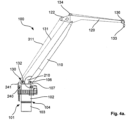
- the upper elbow arm 120 can alternatively be pivotally connected to the main arm 110, as shown in Figure 4a .
- the arm actuator assembly 200 further comprises an elbow drive unit 230 arranged at lower part of the main arm 110 and which is arranged for connection to the tension arm 310, such that the tension arm 310 is arranged extending between the elbow drive unit 230 and the connection link 300.
- the tension arm 310 is connected to a rear end of the elbow arm 120 as shown for a tension wire 311 in Figure 4a .
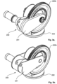
- the elbow drive unit 230 is formed by a single or double torque arm 231, as shown in Figures 3a-b , respectively.
- the single or double torque arm 231 is rotatably connected at a center axis of the main arm drive pinion gear 220b, wherein the torque arm 231 has a longitudinal extension longer than the exterior circumference of the main arm drive pinion gear 220b allowing it to pivot freely about the main arm drive pinion gear 220b.
- the elbow arm 120 will correspondingly move in the vertical plane due to the interaction of the tension arm 310 which is pivotally connected to the elbow drive unit 230 at one end and to the connection link 300 or rear part of the elbow arm 120 at the other end.
- elbow drive unit 230 can e.g. be arranged to a separate attachment lug arranged to the lower part of the main arm 110.
- FIGS 4a-b are principle drawings of an alternative embodiment of the arm actuator assembly 200, which is not a part of the present invention, arranged to a knuckle jib crane 100.
- the elbow arm 120 is pivotally connected to the main arm 110 at a distance from the end of the elbow arm 120, such that the elbow arm 120 exhibits overhang 122 at rear end thereof.
- the arm actuator assembly 200 according to the alternative embodiment comprises three main arm drive pinion gears 220a-c providing a higher moment which is required for a larger crane, compared to the first embodiment, arranged to the main arm 110 by means of separate attachment devices or where two or more pinion gears 220a-c are arranged to a common attachment device, as described in the first embodiment.
- main arm drive pinion gears 220a-c are arranged at lower part and lower end of the main arm 110, and the main arm drive pinion gears 220a-c are distributed along the circumference of the cogwheel 210.
- the arm actuator assembly 200 for operation of the elbow arm 120 comprises a controllable tension winch 240 arranged to the base platform 102 for controlling a tension wire 311 arranged fixed to the overhang 122 at one end, alternatively rear end of a connection link 300 connecting the main arm 110 and elbow arm 120, and running over a pulley 241 and is arranged to the tension winch 240 at the other end.
- the arm actuator assembly 200 in the alternative embodiment is capable of operation of both the main arm 110 and elbow arm 120.
- the tension winch 240 can be controlled to move the elbow arm 120 both in correspondence with the movement of the main arm 110 and separately.
- cranes 100 which comprise both main arm 110 and elbow arm 120 it is obvious for a skilled person that the main principle of the present invention can be used on cranes comprising only one arm or more than two arms.
- Any crane 100 which would require elevation or lowering movement in the vertical plane of an arm 110 pivotally arranged to a base platform 102 at one end can utilize the fixed cogwheel 210 and drive pinion gear(s) 220a-c for operation thereof.
- the arm actuator assembly 200 can comprise only one drive pinion gear 220a-c or several drive pinion gears 220a-c depending on the size/requirements of the crane 100. Further, gear exchanges can be used in connection with the arm drive pinion gear 220a-c if required or desired.
- the arm actuator assembly 200 is provided with safety devices, which will lock the arm drive pinion gear(s) 220a-c at loss of power or fail function.
- the main arm 120 is provided with a safety mechanism that locks the main arm 110 to the fixed cogwheel 210.
- a crane provided with the arm actuator assembly according to the present invention will have a more horizontal load path than conventional cranes and due to that it can be electrically controlled.
- a crane provided with the arm actuator system according to the present invention will be easier and safer to use within automatic operations.
- a crane provided with the arm actuator assembly according to the present invention will provide enhanced monitoring and improved precise control compared to hydraulically operated cranes.
- Remote monitoring of an electrically driven crane provides more accurate state of the crane than hydraulic cranes. This will be beneficial for cranes arranged on unmanned offshore installations. When e.g. a platform is to be manned, one can better predict if the crane is operational or not.
Landscapes
- Engineering & Computer Science (AREA)
- Mechanical Engineering (AREA)
- Jib Cranes (AREA)
Claims (6)
- Ensemble d'actionneur de bras (200) pour une grue (100), comprenant au moins un bras principal (110) agencé en pivotement sur une structure de support (101) à une extrémité inférieure de celle-ci au moyen d'une connexion pivotante (105), l'ensemble d'actionneur de bras (200) comprenant :- au moins une roue dentée (210) agencée avec sa circonférence dans un plan vertical parallèle du bras principal (110) et fixée avec son axe central horizontal qui correspond à l'axe central horizontal de la connexion pivotante (105) entre le bras principal (110) et la structure de support (101),- au moins un pignon d'attaque (220a-c) de bras principal, agencé par rapport au bras principal (110) en prise avec ladite au moins une roue dentée fixe (210),- une unité d'entraînement (230) de bras coudé supérieur pour un bras coudé (120) agencé pour actionner un bras coudé supérieur (120) de la grue (100), l'unité d'entraînement (230) de bras coudé étant formée par un support de couple (231) agencé en pivotement par rapport à un axe central horizontal d'un pignon d'attaque (220b) de bras principal, agencé à une partie arrière du bras principal (110), et comprenant en outre un bras de tension (310) s'étendant entre le bras coudé supérieur (120) et le support de couple (231), le bras de tension (310) étant agencé en pivotement par rapport au bras coudé supérieur (120) et au bras principal (110), respectivement,dans lequel le fonctionnement dudit au moins un pignon d'attaque (220a-c) en prise avec ladite au moins une roue dentée fixe (210) fait monter ou descendre le bras principal (110) de la grue (100) dans le plan vertical.
- Ensemble d'actionneur de bras selon la revendication 1, caractérisé en ce que le support de couple (231) est un support de couple (231) simple ou double.
- Ensemble d'actionneur de bras selon la revendication 1, caractérisé en ce que ladite au moins une roue dentée (210) présente un diamètre supérieur à celui dudit au moins un pignon d'attaque (220a-c) de bras principal.
- Ensemble d'actionneur de bras selon la revendication 1, caractérisé en ce que ledit au moins un pignon d'attaque (220a-c) de bras principal est agencé sur une source d'énergie électrique (225).
- Ensemble d'actionneur de bras selon la revendication 4, caractérisé en ce qu'un dispositif de changement d'engrenage est agencé entre la source d'énergie électrique (225) et le pignon d'attaque (220a-c) de bras principal.
- Ensemble d'actionneur de bras selon la revendication 1, caractérisé en ce que ledit au moins un pignon d'attaque (220a) de bras principal est agencé sur la face inférieure du bras principal (110).
Applications Claiming Priority (2)
| Application Number | Priority Date | Filing Date | Title |
|---|---|---|---|
| NO20170731A NO343046B1 (en) | 2017-05-04 | 2017-05-04 | Arm actuator assembly for a crane |
| PCT/NO2018/050117 WO2018203756A1 (fr) | 2017-05-04 | 2018-05-03 | Ensemble actionneur de bras pour grue |
Publications (4)
| Publication Number | Publication Date |
|---|---|
| EP3619155A1 EP3619155A1 (fr) | 2020-03-11 |
| EP3619155A4 EP3619155A4 (fr) | 2021-03-10 |
| EP3619155B1 true EP3619155B1 (fr) | 2024-10-02 |
| EP3619155C0 EP3619155C0 (fr) | 2024-10-02 |
Family
ID=63960646
Family Applications (1)
| Application Number | Title | Priority Date | Filing Date |
|---|---|---|---|
| EP18793885.7A Active EP3619155B1 (fr) | 2017-05-04 | 2018-05-03 | Ensemble actionneur de bras pour grue |
Country Status (3)
| Country | Link |
|---|---|
| EP (1) | EP3619155B1 (fr) |
| NO (1) | NO343046B1 (fr) |
| WO (1) | WO2018203756A1 (fr) |
Families Citing this family (1)
| Publication number | Priority date | Publication date | Assignee | Title |
|---|---|---|---|---|
| US12060137B2 (en) * | 2019-07-02 | 2024-08-13 | Macartney A/S | Lifting device and methods of operating a lifting device |
Family Cites Families (14)
| Publication number | Priority date | Publication date | Assignee | Title |
|---|---|---|---|---|
| US3221908A (en) * | 1964-02-25 | 1965-12-07 | Beloit Corp | Material handling device |
| DE1260733B (de) * | 1966-05-04 | 1968-02-08 | Herbert Biedermann Dipl Ing | Wippkran, insbesondere Turmdrehkran |
| GB1207505A (en) * | 1967-06-22 | 1970-10-07 | Herbert Clement Tampin | Hoists, particularly roof hoists |
| JPS5539520B2 (fr) * | 1972-11-14 | 1980-10-11 | ||
| AU8321075A (en) * | 1975-07-18 | 1977-01-20 | Foralkranar Ab | Load handler with pantograph-type jib |
| US4268214A (en) * | 1979-03-26 | 1981-05-19 | Bucyrus-Erie Company | Excavator front end |
| US4274778A (en) * | 1979-06-05 | 1981-06-23 | Putnam Paul S | Mechanized stand handling apparatus for drilling rigs |
| JPS6117995Y2 (fr) * | 1981-04-30 | 1986-05-31 | ||
| JPS6044492A (ja) * | 1983-08-19 | 1985-03-09 | 森 敬 | クレ−ン |
| JPH0754227Y2 (ja) * | 1993-12-28 | 1995-12-13 | 株式会社技研製作所 | クレーン車 |
| CA2600932C (fr) | 2007-09-07 | 2010-02-02 | Ems-Tech Inc. | Systeme actionneur pour orientation de fleche |
| DE102010013987B4 (de) * | 2010-04-06 | 2015-07-02 | Sieper Lüdenscheid GmbH & Co. KG | Spielzeug-Frontlader für ein Spielfahrzeug |
| CN202953754U (zh) * | 2012-11-14 | 2013-05-29 | 湖北神河汽车改装(集团)有限公司 | 一种电动平衡吊 |
| CN205709609U (zh) | 2016-04-26 | 2016-11-23 | 北汽福田汽车股份有限公司 | 一种汽车起重机及其臂架对中系统 |
-
2017
- 2017-05-04 NO NO20170731A patent/NO343046B1/en unknown
-
2018
- 2018-05-03 EP EP18793885.7A patent/EP3619155B1/fr active Active
- 2018-05-03 WO PCT/NO2018/050117 patent/WO2018203756A1/fr not_active Ceased
Also Published As
| Publication number | Publication date |
|---|---|
| EP3619155A1 (fr) | 2020-03-11 |
| NO20170731A1 (en) | 2018-10-15 |
| NO343046B1 (en) | 2018-10-15 |
| EP3619155A4 (fr) | 2021-03-10 |
| WO2018203756A1 (fr) | 2018-11-08 |
| EP3619155C0 (fr) | 2024-10-02 |
Similar Documents
| Publication | Publication Date | Title |
|---|---|---|
| US7328811B2 (en) | Even reeving system | |
| US7641421B2 (en) | Offshore vessel | |
| US12172733B2 (en) | Apparatus for launch and recovery of a submersible vessel from and to an off-shore site | |
| EP3072844B1 (fr) | Grue de levage en mer | |
| RU2717111C1 (ru) | Мобильная шахтная лебедка | |
| US3828941A (en) | Hydraulic jib | |
| EP3619155B1 (fr) | Ensemble actionneur de bras pour grue | |
| JPH10279285A (ja) | 旋回ロック機構 | |
| CN108341356B (zh) | 一种用于起重机的应急系统以及起重机 | |
| CN201777375U (zh) | 电驱动一体化控制锚机 | |
| DK202070277A8 (en) | Ship crane with a fish pump | |
| US20100071487A1 (en) | Self contained hydraulic system for a remote controlled unit | |
| NO341416B1 (en) | Knuckle boom crane | |
| CA1044651A (fr) | Commande a battant et regulateur automatique d'arret | |
| KR102278789B1 (ko) | 회전식 천장 크레인 | |
| NO343924B1 (no) | Kransystem for en utligger | |
| CN217350480U (zh) | 起重机 | |
| US11453464B2 (en) | Electrohydraulic device, method, and marine vessel or platform | |
| WO2019158504A1 (fr) | Système de levage en mer | |
| RU2707668C1 (ru) | Монтажное устройство | |
| KR101287388B1 (ko) | 견인장치 | |
| WO2015160305A1 (fr) | Système et procédé d'utilisation d'unités de puissance hydraulique d'un système de levage pour le fonctionnement d'une grue dans une plate-forme de travail auto-élévatrice | |
| KR200331491Y1 (ko) | 유압식 크레인 | |
| SU176811A1 (ru) | Стационарное шлангующее устройство для налива жидкостей | |
| EP2314535B1 (fr) | Dispositif de guidage de pivotement illimité avec le disque d'entraînement actionner par le moteur hydraulique |
Legal Events
| Date | Code | Title | Description |
|---|---|---|---|
| STAA | Information on the status of an ep patent application or granted ep patent |
Free format text: STATUS: THE INTERNATIONAL PUBLICATION HAS BEEN MADE |
|
| PUAI | Public reference made under article 153(3) epc to a published international application that has entered the european phase |
Free format text: ORIGINAL CODE: 0009012 |
|
| STAA | Information on the status of an ep patent application or granted ep patent |
Free format text: STATUS: REQUEST FOR EXAMINATION WAS MADE |
|
| 17P | Request for examination filed |
Effective date: 20191128 |
|
| AK | Designated contracting states |
Kind code of ref document: A1 Designated state(s): AL AT BE BG CH CY CZ DE DK EE ES FI FR GB GR HR HU IE IS IT LI LT LU LV MC MK MT NL NO PL PT RO RS SE SI SK SM TR |
|
| AX | Request for extension of the european patent |
Extension state: BA ME |
|
| DAV | Request for validation of the european patent (deleted) | ||
| DAX | Request for extension of the european patent (deleted) | ||
| A4 | Supplementary search report drawn up and despatched |
Effective date: 20210208 |
|
| RIC1 | Information provided on ipc code assigned before grant |
Ipc: B66C 23/82 20060101ALI20210202BHEP Ipc: B66C 23/14 20060101AFI20210202BHEP Ipc: B66C 23/62 20060101ALI20210202BHEP |
|
| P01 | Opt-out of the competence of the unified patent court (upc) registered |
Effective date: 20230526 |
|
| GRAP | Despatch of communication of intention to grant a patent |
Free format text: ORIGINAL CODE: EPIDOSNIGR1 |
|
| STAA | Information on the status of an ep patent application or granted ep patent |
Free format text: STATUS: GRANT OF PATENT IS INTENDED |
|
| INTG | Intention to grant announced |
Effective date: 20240430 |
|
| GRAS | Grant fee paid |
Free format text: ORIGINAL CODE: EPIDOSNIGR3 |
|
| GRAA | (expected) grant |
Free format text: ORIGINAL CODE: 0009210 |
|
| STAA | Information on the status of an ep patent application or granted ep patent |
Free format text: STATUS: THE PATENT HAS BEEN GRANTED |
|
| AK | Designated contracting states |
Kind code of ref document: B1 Designated state(s): AL AT BE BG CH CY CZ DE DK EE ES FI FR GB GR HR HU IE IS IT LI LT LU LV MC MK MT NL NO PL PT RO RS SE SI SK SM TR |
|
| REG | Reference to a national code |
Ref country code: GB Ref legal event code: FG4D |
|
| REG | Reference to a national code |
Ref country code: CH Ref legal event code: EP |
|
| REG | Reference to a national code |
Ref country code: DE Ref legal event code: R096 Ref document number: 602018074983 Country of ref document: DE |
|
| REG | Reference to a national code |
Ref country code: IE Ref legal event code: FG4D |
|
| U01 | Request for unitary effect filed |
Effective date: 20241022 |
|
| U07 | Unitary effect registered |
Designated state(s): AT BE BG DE DK EE FI FR IT LT LU LV MT NL PT RO SE SI Effective date: 20241105 |
|
| P04 | Withdrawal of opt-out of the competence of the unified patent court (upc) registered |
Free format text: CASE NUMBER: APP_59257/2024 Effective date: 20241030 |
|
| PG25 | Lapsed in a contracting state [announced via postgrant information from national office to epo] |
Ref country code: HR Free format text: LAPSE BECAUSE OF FAILURE TO SUBMIT A TRANSLATION OF THE DESCRIPTION OR TO PAY THE FEE WITHIN THE PRESCRIBED TIME-LIMIT Effective date: 20241002 Ref country code: IS Free format text: LAPSE BECAUSE OF FAILURE TO SUBMIT A TRANSLATION OF THE DESCRIPTION OR TO PAY THE FEE WITHIN THE PRESCRIBED TIME-LIMIT Effective date: 20250202 |
|
| PG25 | Lapsed in a contracting state [announced via postgrant information from national office to epo] |
Ref country code: ES Free format text: LAPSE BECAUSE OF FAILURE TO SUBMIT A TRANSLATION OF THE DESCRIPTION OR TO PAY THE FEE WITHIN THE PRESCRIBED TIME-LIMIT Effective date: 20241002 |
|
| PG25 | Lapsed in a contracting state [announced via postgrant information from national office to epo] |
Ref country code: NO Free format text: LAPSE BECAUSE OF FAILURE TO SUBMIT A TRANSLATION OF THE DESCRIPTION OR TO PAY THE FEE WITHIN THE PRESCRIBED TIME-LIMIT Effective date: 20250102 |
|
| PG25 | Lapsed in a contracting state [announced via postgrant information from national office to epo] |
Ref country code: GR Free format text: LAPSE BECAUSE OF FAILURE TO SUBMIT A TRANSLATION OF THE DESCRIPTION OR TO PAY THE FEE WITHIN THE PRESCRIBED TIME-LIMIT Effective date: 20250103 |
|
| PG25 | Lapsed in a contracting state [announced via postgrant information from national office to epo] |
Ref country code: PL Free format text: LAPSE BECAUSE OF FAILURE TO SUBMIT A TRANSLATION OF THE DESCRIPTION OR TO PAY THE FEE WITHIN THE PRESCRIBED TIME-LIMIT Effective date: 20241002 Ref country code: CZ Free format text: LAPSE BECAUSE OF FAILURE TO SUBMIT A TRANSLATION OF THE DESCRIPTION OR TO PAY THE FEE WITHIN THE PRESCRIBED TIME-LIMIT Effective date: 20241002 |
|
| PG25 | Lapsed in a contracting state [announced via postgrant information from national office to epo] |
Ref country code: RS Free format text: LAPSE BECAUSE OF FAILURE TO SUBMIT A TRANSLATION OF THE DESCRIPTION OR TO PAY THE FEE WITHIN THE PRESCRIBED TIME-LIMIT Effective date: 20250102 |
|
| U1N | Appointed representative for the unitary patent procedure changed after the registration of the unitary effect |
Representative=s name: METIDA; LT |
|
| PG25 | Lapsed in a contracting state [announced via postgrant information from national office to epo] |
Ref country code: SM Free format text: LAPSE BECAUSE OF FAILURE TO SUBMIT A TRANSLATION OF THE DESCRIPTION OR TO PAY THE FEE WITHIN THE PRESCRIBED TIME-LIMIT Effective date: 20241002 |
|
| PG25 | Lapsed in a contracting state [announced via postgrant information from national office to epo] |
Ref country code: SK Free format text: LAPSE BECAUSE OF FAILURE TO SUBMIT A TRANSLATION OF THE DESCRIPTION OR TO PAY THE FEE WITHIN THE PRESCRIBED TIME-LIMIT Effective date: 20241002 |
|
| PLBE | No opposition filed within time limit |
Free format text: ORIGINAL CODE: 0009261 |
|
| STAA | Information on the status of an ep patent application or granted ep patent |
Free format text: STATUS: NO OPPOSITION FILED WITHIN TIME LIMIT |
|
| 26N | No opposition filed |
Effective date: 20250703 |
|
| REG | Reference to a national code |
Ref country code: CH Ref legal event code: H13 Free format text: ST27 STATUS EVENT CODE: U-0-0-H10-H13 (AS PROVIDED BY THE NATIONAL OFFICE) Effective date: 20251223 |
|
| PG25 | Lapsed in a contracting state [announced via postgrant information from national office to epo] |
Ref country code: CH Free format text: LAPSE BECAUSE OF NON-PAYMENT OF DUE FEES Effective date: 20250531 |
|
| U90 | Renewal fees not paid: noting of loss of rights |
Free format text: RENEWAL FEE NOT PAID FOR YEAR 08 Effective date: 20251219 |
|
| GBPC | Gb: european patent ceased through non-payment of renewal fee |
Effective date: 20250503 |
|
| PG25 | Lapsed in a contracting state [announced via postgrant information from national office to epo] |
Ref country code: MC Free format text: LAPSE BECAUSE OF FAILURE TO SUBMIT A TRANSLATION OF THE DESCRIPTION OR TO PAY THE FEE WITHIN THE PRESCRIBED TIME-LIMIT Effective date: 20241002 |
|
| U93 | Unitary patent lapsed |
Free format text: RENEWAL FEE NOT PAID Effective date: 20250531 |
|
| PG25 | Lapsed in a contracting state [announced via postgrant information from national office to epo] |
Ref country code: GB Free format text: LAPSE BECAUSE OF NON-PAYMENT OF DUE FEES Effective date: 20250503 |
|
| PG25 | Lapsed in a contracting state [announced via postgrant information from national office to epo] |
Ref country code: IE Free format text: LAPSE BECAUSE OF NON-PAYMENT OF DUE FEES Effective date: 20250503 |