EP3619945B1 - Vorrichtung und verfahren zur erzeugung eines pufferstatusberichts - Google Patents
Vorrichtung und verfahren zur erzeugung eines pufferstatusberichts Download PDFInfo
- Publication number
- EP3619945B1 EP3619945B1 EP18795180.1A EP18795180A EP3619945B1 EP 3619945 B1 EP3619945 B1 EP 3619945B1 EP 18795180 A EP18795180 A EP 18795180A EP 3619945 B1 EP3619945 B1 EP 3619945B1
- Authority
- EP
- European Patent Office
- Prior art keywords
- numerology
- bsr
- priority
- buffer size
- logical channel
- Prior art date
- Legal status (The legal status is an assumption and is not a legal conclusion. Google has not performed a legal analysis and makes no representation as to the accuracy of the status listed.)
- Active
Links
Images


Classifications
-
- H—ELECTRICITY
- H04—ELECTRIC COMMUNICATION TECHNIQUE
- H04W—WIRELESS COMMUNICATION NETWORKS
- H04W28/00—Network traffic management; Network resource management
- H04W28/02—Traffic management, e.g. flow control or congestion control
- H04W28/0278—Traffic management, e.g. flow control or congestion control using buffer status reports
-
- H—ELECTRICITY
- H04—ELECTRIC COMMUNICATION TECHNIQUE
- H04W—WIRELESS COMMUNICATION NETWORKS
- H04W72/00—Local resource management
- H04W72/20—Control channels or signalling for resource management
- H04W72/21—Control channels or signalling for resource management in the uplink direction of a wireless link, i.e. towards the network
-
- H—ELECTRICITY
- H04—ELECTRIC COMMUNICATION TECHNIQUE
- H04W—WIRELESS COMMUNICATION NETWORKS
- H04W72/00—Local resource management
- H04W72/20—Control channels or signalling for resource management
- H04W72/23—Control channels or signalling for resource management in the downlink direction of a wireless link, i.e. towards a terminal
-
- H—ELECTRICITY
- H04—ELECTRIC COMMUNICATION TECHNIQUE
- H04W—WIRELESS COMMUNICATION NETWORKS
- H04W72/00—Local resource management
- H04W72/50—Allocation or scheduling criteria for wireless resources
- H04W72/56—Allocation or scheduling criteria for wireless resources based on priority criteria
- H04W72/566—Allocation or scheduling criteria for wireless resources based on priority criteria of the information or information source or recipient
- H04W72/569—Allocation or scheduling criteria for wireless resources based on priority criteria of the information or information source or recipient of the traffic information
Definitions
- the present invention relates to wireless communication, and more particularly, to apparatus and method for generating buffer status report.
- LTE 3rd Generation Partnership Project Long Term Evolution
- FIG. 1 is a block diagram illustrating network structure of an evolved universal mobile telecommunication system (E-UMTS).
- E-UMTS may be also referred to as an LTE system.
- the communication network is widely deployed to provide a variety of communication services such as voice (VoIP) through IMS and packet data.
- VoIP voice
- IMS packet data
- the E-UMTS network includes an evolved UMTS terrestrial radio access network (E-UTRAN), an Evolved Packet Core (EPC) and one or more user equipment.
- the E-UTRAN may include one or more evolved NodeB (eNodeB) 20, and a plurality of user equipment (UE) 10 may be located in one cell.
- eNodeB evolved NodeB
- UE user equipment
- MME mobility management entity
- downlink refers to communication from eNodeB 20 to UE 10
- uplink refers to communication from the UE to an eNodeB.
- UE 10 refers to communication equipment carried by a user and may be also referred to as a mobile station (MS), a user terminal (UT), a subscriber station (SS) or a wireless device.
- eNode B 20 may be reffered to as eNB and gNode B (gNB), etc. However, in the following explanation, the term 'UE' and 'eNodeB' are used for convenience.
- FIG. 2 is a block diagram depicting architecture of a typical E-UTRAN and a typical EPC.
- an eNodeB 20 provides end points of a user plane and a control plane to the UE 10.
- MME/SAE gateway 30 provides an end point of a session and mobility management function for UE 10.
- the eNodeB and MME/SAE gateway may be connected via an S1 interface.
- the eNodeB 20 is generally a fixed station that communicates with a UE 10, and may also be referred to as a base station (BS) or an access point.
- BS base station
- One eNodeB 20 may be deployed per cell.
- An interface for transmitting user traffic or control traffic may be used between eNodeBs 20.
- the MME provides various functions including NAS signaling to eNodeBs 20, NAS signaling security, AS Security control, Inter CN node signaling for mobility between 3GPP access networks, Idle mode UE Reachability (including control and execution of paging retransmission), Tracking Area list management (for UE in idle and active mode), PDN GW and Serving GW selection, MME selection for handovers with MME change, SGSN selection for handovers to 2G or 3G 3GPP access networks, Roaming, Authentication, Bearer management functions including dedicated bearer establishment, Support for PWS (which includes ETWS and CMAS) message transmission.
- the SAE gateway host provides assorted functions including Per-user based packet filtering (by e.g.
- MME/SAE gateway 30 will be referred to herein simply as a "gateway,” but it is understood that this entity includes both an MME and an SAE gateway.
- a plurality of nodes may be connected between eNodeB 20 and gateway 30 via the S1 interface.
- the eNodeBs 20 may be connected to each other via an X2 interface and neighboring eNodeBs may have a meshed network structure that has the X2 interface.
- eNodeB 20 may perform functions of selection for gateway 30, routing toward the gateway during a Radio Resource Control (RRC) activation, scheduling and transmitting of paging messages, scheduling and transmitting of Broadcast Channel (BCCH) information, dynamic allocation of resources to UEs 10 in both uplink and downlink, configuration and provisioning of eNodeB measurements, radio bearer control, radio admission control (RAC), and connection mobility control in LTE_ACTIVE state.
- gateway 30 may perform functions of paging origination, LTE-IDLE state management, ciphering of the user plane, System Architecture Evolution (SAE) bearer control, and ciphering and integrity protection of Non-Access Stratum (NAS) signaling.
- SAE System Architecture Evolution
- NAS Non-Access Stratum
- the EPC includes a mobility management entity (MME), a serving-gateway (S-GW), and a packet data network-gateway (PDN-GW).
- MME mobility management entity
- S-GW serving-gateway
- PDN-GW packet data network-gateway
- FIG. 3 is a diagram showing a control plane and a user plane of a radio interface protocol between a UE and an E-UTRAN based on a 3GPP radio access network standard.
- the control plane refers to a path used for transmitting control messages used for managing a call between the UE and the E-UTRAN.
- the user plane refers to a path used for transmitting data generated in an application layer, e.g., voice data or Internet packet data.
- a physical (PHY) layer (L1) of a first layer provides an information transfer service to a higher layer using a physical channel.
- the PHY layer is connected to a medium access control (MAC) layer located on the higher layer via a transport channel.
- Data is transported between the MAC layer and the PHY layer via the transport channel.
- Data is transported between a physical layer of a transmitting side and a physical layer of a receiving side via physical channels.
- the physical channels use time and frequency as radio resources.
- the physical channel is modulated using an orthogonal frequency division multiple access (OFDMA) scheme in downlink and is modulated using a single carrier frequency division multiple access (SC-FDMA) scheme in uplink.
- OFDMA orthogonal frequency division multiple access
- SC-FDMA single carrier frequency division multiple access
- the MAC layer (L2) of a second layer provides a service to a radio link control (RLC) layer of a higher layer via a logical channel.
- the RLC layer of the second layer supports reliable data transmission.
- a function of the RLC layer may be implemented by a functional block of the MAC layer.
- a packet data convergence protocol (PDCP) layer of the second layer performs a header compression function to reduce unnecessary control information for efficient transmission of an Internet protocol (IP) packet such as an IP version 4 (IPv4) packet or an IP version 6 (IPv6) packet in a radio interface having a relatively small bandwidth.
- IP Internet protocol
- IPv4 IP version 4
- IPv6 IP version 6
- a radio resource control (RRC) layer located at the bottom of a third layer is defined only in the control plane.
- the RRC layer controls logical channels, transport channels, and physical channels in relation to configuration, re-configuration, and release of radio bearers (RBs).
- An RB refers to a service that the second layer provides for data transmission between the UE and the E-UTRAN.
- the RRC layer of the UE and the RRC layer of the E-UTRAN exchange RRC messages with each other.
- One cell of the eNB is set to operate in one of bandwidths such as 1.25, 2.5, 5, 10, 15, and 20MHz and provides a downlink or uplink transmission service to a plurality of UEs in the bandwidth. Different cells may be set to provide different bandwidths.
- Downlink transport channels for transmission of data from the E-UTRAN to the UE include a broadcast channel (BCH) for transmission of system information, a paging channel (PCH) for transmission of paging messages, and a downlink shared channel (SCH) for transmission of user traffic or control messages.
- BCH broadcast channel
- PCH paging channel
- SCH downlink shared channel
- Traffic or control messages of a downlink multicast or broadcast service may be transmitted through the downlink SCH and may also be transmitted through a separate downlink multicast channel (MCH).
- MCH downlink multicast channel
- Uplink transport channels for transmission of data from the UE to the E-UTRAN include a random access channel (RACH) for transmission of initial control messages and an uplink SCH for transmission of user traffic or control messages.
- Logical channels that are defined above the transport channels and mapped to the transport channels include a broadcast control channel (BCCH), a paging control channel (PCCH), a common control channel (CCCH), a multicast control channel (MCCH), and a multicast traffic channel (MTCH).
- BCCH broadcast control channel
- PCCH paging control channel
- CCCH common control channel
- MCCH multicast control channel
- MTCH multicast traffic channel
- NR New Radio Access Technology
- NR Random access
- RA random access
- An object of the present invention devised to solve the problem lies in method for a user equipment (UE) transmitting a buffer status report (BSR).
- UE user equipment
- BSR buffer status report
- Another object of the present invention is to provide a user equipment (UE) for transmitting a buffer status report (BSR).
- UE user equipment
- BSR buffer status report
- the object of the present invention can be achieved by providing a method according to claim 1.
- the numerology priority can be configured by the network.
- the numerology priority of a numerology is determined by the UE based on a highest logical channel priority of the logical channels which are mapped to the numerology, wherein the logical channel priority can be configured by the network.
- Priority of a first numerology mapped to a first set of logical channels is higher than that of a second numerology mapped to a second set of logical channels if a highest logical channel priority of the first set of the logical channels is higher than a highest logical channel priority of the second set of the logical channels.
- the generating comprises truncating buffer size information of at least one numerology in increasing order of numerology priority when an uplink grant is not enough to include buffer size information of each of numerologies in the BSR.
- the calculating the buffer size of each numerology comprises calculating a first sum of buffer sizes of logical channels mapped to a first numerology; and calculating a second sum of buffer sizes of logical channels mapped to a second numerology.
- the method further comprises transmitting the BSR to the network.
- a user equipment configured to claim 8.
- the numerology priority is configured by the network.
- the processor is configured to determine numerology priority of a numerology based on a highest logical channel priority of the logical channels which are mapped to the numerology, wherein the logical channel priority is configured by the network. Priority of a first numerology mapped to a first set of logical channels is higher than that of a second numerology mapped to a second set of logical channels if a highest logical channel priority of the first set of the logical channels is higher than a highest logical channel priority of the second set of the logical channels.
- the processor is configured to truncate buffer size information of at least one numerology in increasing order of numerology priority when an uplink grant is not enough to include buffer size information of each of numerologies in the BSR.
- the processor is configured to: calculate a first sum of buffer sizes of logical channels mapped to a first numerology; and calculate a second sum of buffer sizes of logical channels mapped to a second numerology.
- the UE can generate BSR by truncating numerology or including selected numerology when uplink grant is not enough to include buffer size for all numerologies so that communication performance is enhanced.
- the Buffer Status reporting procedure is used to provide the serving eNB with information about the amount of data available for transmission in the UL buffers associated with the MAC entity.
- RRC controls BSR reporting by configuring the three timers periodicBSR-Timer, retxBSR-Timer and logicalChannelSR-ProhibitTimer and by, for each logical channel, optionally signalling logicalChannelGroup which allocates the logical channel to an LCG (Logical Channel Group).
- the MAC entity shall consider all radio bearers which are not suspended and may consider radio bearers which are suspended.
- the Long BSR is not supported and all logical channels belong to one LCG.
- a Buffer Status Report shall be triggered if any of the following events occur:
- a MAC PDU shall contain at most one MAC BSR control element, even when multiple events trigger a BSR by the time a BSR can be transmitted in which case the Regular BSR and the Periodic BSR shall have precedence over the padding BSR.
- the MAC entity shall restart retxBSR-Timer upon indication of a grant for transmission of new data on any UL-SCH.
- All triggered BSRs shall be cancelled in case the UL grant(s) in this TTI can accommodate all pending data available for transmission but is not sufficient to additionally accommodate the BSR MAC control element plus its subheader. All triggered BSRs shall be cancelled when a BSR is included in a MAC PDU for transmission.
- the MAC entity shall transmit at most one Regular/Periodic BSR in a TTI. If the MAC entity is requested to transmit multiple MAC PDUs in a TTI, it may include a padding BSR in any of the MAC PDUs which do not contain a Regular/Periodic BSR.
- All BSRs transmitted in a TTI always reflect the buffer status after all MAC PDUs have been built for this TTI.
- Each LCG shall report at the most one buffer status value per TTI and this value shall be reported in all BSRs reporting buffer status for this LCG.
- a Padding BSR is not allowed to cancel a triggered Regular/Periodic BSR, except for NB-IoT.
- a Padding BSR is triggered for a specific MAC PDU only and the trigger is cancelled when this MAC PDU has been built.
- FIG. 4 is a diagram illustrating a short BSR and Truncated BSR MAC control element
- FIG. 5 is a diagram illustrating a long BSR and Truncated BSR MAC control element.
- BSR Buffer Status Report
- the Table 1 illustrates a buffer size levels for BSR.
- Index Buffer Size (BS) value [bytes]
- Index Buffer Size (BS) value [bytes]
- BS Index Buffer Size
- the Table 2 illustrates extended Buffer size levels for BSR.
- Index Buffer Size (BS) value [bytes]
- Index Buffer Size (BS) value [bytes]
- BS Index Buffer Size
- the BSR formats are identified by MAC PDU subheaders with LCIDs as specified in the Table 2.
- the existing LTE BSR framework is used as baseline for NR BSR framework. Further enhancements at least related to numerologies and granularity and can be further discussed.
- Single logical channel can be mapped to one or more numerology/ TTI duration. ARQ can be performed on any numerologies/TTI lengths that the LCH is mapped to.
- the RLC configuration is per logical channel without dependency on numerology/TTI length.
- Logical channel to numerology/TTI length mapping can be reconfigured via RRC reconfiguration.
- a single MAC entity can support one or more numerology/TTI durations.
- Logical Channel Prioritization (LCP) takes into account the mapping of logical channel to one or more numerology/TTI duration.
- FIG. 6 is a diagram illustrating Sidelink BSR and Truncated Sidelink BSR MAC control element for even N
- FIG. 7 is a diagram illustrating Sidelink BSR and Truncated Sidelink BSR MAC control element for odd N.
- Sidelink BSR and Truncated Sidelink BSR MAC control elements consist of one Destination Index field, one LCG ID field and one corresponding Buffer Size field per reported target group.
- the Sidelink BSR MAC control elements are identified by MAC PDU subheaders with LCIDs as specified in table 3. They have variable sizes.
- the Table 3 illustrates values of LCID for UL-SCH.
- Index LCID values 00000 CCCH 00001-01010 Identity of the logical channel 01011 CCCH 01100 CCCH 01101-10011 Reserved 10100 Recommended bit rate query 10101 SPS confirmation 10110 Truncated Sidelink BSR 10111 Sidelink BSR 11000 Dual Connectivity Power Headroom Report 11001 Extended Power Headroom Report 11010 Power Headroom Report 11011 C-RNTI 11100 Truncated BSR 11101 Short BSR 11110 Long BSR 11111 Padding
- Buffer Sizes of LCGs are included in decreasing order of the highest priority of the sidelink logical channel belonging to the LCG irrespective of the value of the Destination Index field.
- numerology refers to OFDM Subcarrier Spacing (OFDM SCS), Cyclic Prefix (CP) length, Transmission Time Interval (TTI) length, sampling time, OFDM symbol duration, and so on.
- OFDM SCS OFDM Subcarrier Spacing
- CP Cyclic Prefix
- TTI Transmission Time Interval
- sampling time OFDM symbol duration
- URLLC ultra-reliable and low- latency communication
- the network In order to schedule uplink resource with proper numerology, the network needs to know the amount of data that can be transmitted by using the uplink resource with a numerology. One simple way to do this is to report BSR per numerology.
- a UE is configured with a logical channel which is mapped to at least two numerologies.
- the UE when the UE generates a BSR, the UE includes the buffer size of a numerology to the BSR in decreasing order of the priority of the numerology regardless of a logical channel priority considered in the buffer size of the numerology.
- the UE receives information related to logical channel configuration (variously called as logical channel configuration information, etc.) from a network (e.g., gNode B).
- a network e.g., gNode B
- the logical channel configuration information includes information related to a plurality of numerologies mapped to each logical channel.
- the logical channel configuration information may include (1) information of the logical channel identity and (2) information of one or more numerologies mapped to each logical channel.
- the UE may receive numerology priority configuration information from the network.
- the numerology priority configuration information may indicate as following information.
- the UE When the UE triggers a BSR or BSR is triggered, the UE generates the BSR MAC CE by including the buffer size (BS) of a numerology in decreasing order of a numerology priority as following method.
- BS buffer size
- the UE may truncate the BSR MAC CE in increasing order of numerology priority. In other words, the UE does not include a buffer size (BS) of a numerology with lower numerology priority but the UE includes a buffer size (BS) of a numerology with higher numerology priority in the BSR MAC CE.
- BS buffer size
- the UE may truncate the BSR MAC CE by truncating buffer size information of N2 to according to increasing order of numerology priority.
- the UE may truncate the BSR MAC CE, the truncated BSR MAC CE includes as many numerologies having non-zero buffer size (BS) as possible by taking the uplink grant size into account.
- BS buffer size
- FIG. 8 is a diagram illustrating the embodiment 1 according to the present invention.
- a UE may receive logical channel configuration information from a network (e.g., gNode B).
- the logical channel configuration information includes information related to a plurality of numerologies mapped to each logical channel. Referring the FIG. 8 , numerology 1 (N1) is mapped to logical channel 3 (L3) and logical channel (L4) and numerology 2 (N2) is mapped to logical channel 1 (L1) and logical channel 2 (L2).
- the UE may receive information related to numerology priority (e.g., variously called as numerology priority configuration information, numerology priority information, etc.) from the network (e.g., gNode B). Assume that priority of N1 is higher than priority of N2.
- the UE may be configured with logical channels (e.g., LC1, LC2, LC3, and LC4). As shown in FIG. 8 , the priority of the logical channels (LC1, LC2, LC3, and LC4) is represented as P1, P2, P4, and P3, respectively.
- the priority of the logical channels is in decreasing order of P1, P2, P3, and P4, i.e., P1 has the highest priority and P4 has the lowest priority.
- the UE calculates a buffer size (BS) of each numerology.
- buffer size (BS) of N1 is calculated as the sum of buffer size (BS) of LC3 and LC4 by the UE.
- Buffer size (BS) of N2 is calculated as the sum of buffer size (BS) LC2, LC3 and LC4 by the UE.
- the UE check numerology priority of N1 and N2. Since priority of N1 is higher than that of N2, the UE first includes the buffer size (BS) of N1 to BSR, and followed by the buffer size (BS) of N2.
- the UE transmits the generated BSR (e.g., as type of BSR MAC CE) to the network.
- a UE may be configured with a logical channel which is mapped to at least two numerologies.
- the UE When the UE generates a BSR, the UE includes the buffer size of a numerology to the BSR in decreasing order of the highest priority of the logical channel considered in the buffer size of the numerology.
- the UE may receive logical channel configuration information from a network (e.g., gNode B).
- the logical channel configuration information may include (1) information of the logical channel identity and (2) information of one or more numerologies mapped to each logical channel.
- the UE When the UE triggers a BSR or the BSR is triggered, the UE generates the BSR MAC CE by including a buffer size (BS) of a numerology in decreasing order of the highest priority of the logical channel considered in the buffer size (BS) of the numerology.
- the buffer size (BS) of a numerology having the highest priority of the logical channel is included first to the BSR, and followed by a buffer size (BS) of the numerology having the next highest priority of the logical channel.
- the logical channel has data available for transmission.
- the logical channel is the logical channel of which amount of data is calculated into the buffer size (BS) of the numerology.
- the UE doesn't take the priority of the logical channel into account when checking the highest priority of logical channel for a numerology.
- the UE truncates the BSR MAC CE in increasing order of numerology priority, i.e., the UE does not include a buffer size (BS) of a numerology with lower numerology priority but the UE includes a buffer size (BS) of a numerology with higher numerology priority in the BSR MAC CE.
- the UE may truncate the BSR MAC CE by truncating buffer size information of N2 to according to increasing order of numerology priority.
- the UE truncates the BSR MAC CE, the truncated BSR MAC CE includes as many numerologies having non-zero buffer size (BS) as possible by taking the uplink grant size into account.
- FIG. 9 is a diagram illustrating the embodiment 2 according to the present invention.
- a UE may receive logical channel configuration information from a network (e.g., gNode B).
- the logical channel configuration information includes information related to one or more numerologies mapped to each logical channel. Referring the FIG. 9 , numerology 1 (N1) is mapped to logical channel 3 (L3) and logical channel (L4), and numerology 2 (N2) is mapped to logical channel 1 (L1), logical channel 2 (L2), and logical channel 3 (L3).
- the UE may receive information related to numerology priority (e.g., variously called as numerology priority configuration information, numerology priority information, etc.) from the network (e.g., gNode B). Assume that priority of N1 is higher than priority of N2.
- the UE may be configured with logical channels (e.g., LC1, LC2, LC3 and LC4). As shown in FIG. 9 , the priority of the logical channels (LC1, LC2, LC3, and LC4) is represented as P1, P2, P4, and P3, respectively.
- the priority of the logical channels is in decreasing order of P1, P2, P3, and P4, i.e., P1 has the highest priority and P4 has the lowest priority.
- the UE triggers a BSR.
- BSR MAC CE when the UE triggers a BSR and the BSR is trigged, the UE calculates a buffer size (BS) of each numerology.
- the buffer size (BS) of N1 is calculated as sum of buffer size (BS) of LC3 and LC4 by the UE.
- the buffer size (BS) of N2 is calculated as sum of LC1, LC2, and LC3 by the UE.
- the UE checks what logical channel is a highest priority in logical channels of N1 and what logical channel is a highest priority in logical channels of N2. Referring to FIG.
- a highest priority in logical channels of N1 is P3, a highest priority in logical channels of N2 is P1.
- the UE first includes the buffer size (BS) of N2 followed by the buffer size (BS) of N1 as the highest priority of logical channel of N1, i.e., P3, is lower than the highest priority of logical channel of N2, i.e., P1.
- the UE transmits the generated BSR (as type of BSR MAC CE) to the network.
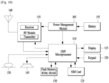
- FIG. 10 is a block diagram of an apparatus (e.g., communication apparatus) according to an embodiment of the present invention.
- the apparatus shown in FIG. 10 can be a user equipment (UE) and/or eNB adapted to perform the above mechanism, but it can be any apparatus for performing the same operation.
- UE user equipment
- eNB evolved node B
- the apparatus may comprise a DSP/microprocessor (110) and RF module (transceiver; 135).
- the DSP/microprocessor (110) is electrically connected with the transceiver (135) and controls it.
- the apparatus may further include power management module (105), battery (155), display (115), keypad (120), SIM card (125), memory device (130), speaker (145) and input device (150), based on its implementation and designer's choice.
- FIG. 10 may represent a UE comprising a receiver (135) configured to receive signal from the network, and a transmitter (135) configured to transmit signals to the network.
- the receiver and transmitter can constitute the transceiver (135).
- the UE further comprises a processor (110) connected to the transceiver (135: receiver and transmitter).
- FIG. 10 may represent a network apparatus comprising a transmitter (135) configured to transmit signals to a UE and a receiver (135) configured to receive signal from the UE. These transmitter and receiver may constitute the transceiver (135).
- the network further comprises a processor (110) connected to the transmitter and the receiver.
- a specific operation described as performed by the BS may be performed by an upper node of the BS. Namely, it is apparent that, in a network comprised of a plurality of network nodes including a BS, various operations performed for communication with an MS may be performed by the BS, or network nodes other than the BS.
- the term ⁇ eNB' may be replaced with the term 'fixed station', ⁇ Node B', ⁇ Base Station (BS)', ⁇ access point', 'gNB', etc.
- the method according to the embodiments of the present invention may be implemented by one or more Application Specific Integrated Circuits (ASICs), Digital Signal Processors (DSPs), Digital Signal Processing Devices (DSPDs), Programmable Logic Devices (PLDs), Field Programmable Gate Arrays (FPGAs), processors, controllers, microcontrollers, or microprocessors.
- ASICs Application Specific Integrated Circuits
- DSPs Digital Signal Processors
- DSPDs Digital Signal Processing Devices
- PLDs Programmable Logic Devices
- FPGAs Field Programmable Gate Arrays
- processors controllers, microcontrollers, or microprocessors.
- the method according to the embodiments of the present invention may be implemented in the form of modules, procedures, functions, etc. performing the above-described functions or operations.
- Software code may be stored in a memory unit and executed by a processor.
- the memory unit may be located at the interior or exterior of the processor and may transmit and receive data to and from the processor via various known means.
- BSR buffer status report
Landscapes
- Engineering & Computer Science (AREA)
- Computer Networks & Wireless Communication (AREA)
- Signal Processing (AREA)
- Mobile Radio Communication Systems (AREA)
Claims (13)
- Verfahren für eine Benutzerausrüstung, UE, die einen Pufferstatusbericht, BSR, erzeugt, wobei das Verfahren umfasst:Empfangen von Konfigurationsinformationen für logische Kanäle von einem Netzwerk, wobei die Konfigurationsinformationen für logische Kanäle Informationen einschließen, die sich auf eine Vielzahl von Numerologien beziehen, die auf jeden logischen Kanal abgebildet werden;Berechnen einer Puffergröße jeder Numerologie auf Basis der Konfigurationsinformationen für logische Kanäle, wenn der BSR ausgelöst wird;Erzeugen eines BSR, der Informationen über die Puffergröße mindestens einer Numerologie in absteigender Reihenfolge der Numerologiepriorität einschließt, ungeachtet einer Priorität von logischen Kanälen, die bei der Puffergröße der Numerologie berücksichtigt wird,wobei die Informationen über die Puffergröße eine Vielzahl von Puffergrößenwerten einschließen,wobei der Puffergrößenwert einer ersten Numerologie, die eine höchste Numerologiepriorität aufweist, als erstes in den BSR eingeschlossen wird, gefolgt vom Puffergrößenwert einer zweiten Numerologie, die eine nächsthöhere Numerologiepriorität aufweist; undÜbertragen des BSR an das Netzwerk.
- Verfahren nach Anspruch 1, wobei die Numerologiepriorität vom Netzwerk konfiguriert wird.
- Verfahren nach Anspruch 1, wobei die Numerologiepriorität einer Numerologie von der UE bestimmt wird,
wobei die Priorität von logischen Kanälen vom Netzwerk konfiguriert wird. - Verfahren nach Anspruch 3, wobei die Priorität einer ersten Numerologie, die auf einen ersten Satz von logischen Kanälen abgebildet wird, höher ist als die einer zweiten Numerologie, die auf einen zweiten Satz von logischen Kanälen abgebildet wird, wenn eine höchste Priorität von logischen Kanälen des ersten Satzes der logischen Kanäle höher ist als eine höchste Priorität von logischen Kanälen des zweiten Satzes der logischen Kanäle.
- Verfahren nach Anspruch 1, wobei das Erzeugen das Abschneiden von Informationen über die Puffergröße mindestens einer Numerologie in aufsteigender Reihenfolge der Numerologiepriorität umfasst, wenn eine Aufwärtsstreckengewährung nicht ausreicht, um Informationen über die Puffergröße jeder der Numerologien in den BSR einzuschließen.
- Verfahren nach Anspruch 1, weiter umfassend:
Übertragen des BSR an das Netzwerk. - Verfahren nach Anspruch 1, wobei das Berechnen der Puffergröße jeder Numerologie umfasst:Berechnen einer ersten Summe von Puffergrößen von logischen Kanälen, die auf eine erste Numerologie abgebildet werden; undBerechnen einer zweiten Summe von Puffergrößen von logischen Kanälen, die auf eine zweite Numerologie abgebildet werden.
- Benutzerausrüstung, UE, die einen Pufferstatusbericht, BSR, erzeugt, wobei die UE umfasst:einen Empfänger, der so konfiguriert ist, dass er Konfigurationsinformationen für logische Kanäle von einem Netzwerk empfängt, wobei die Konfigurationsinformationen für logische Kanäle Informationen einschließen, die sich auf eine Vielzahl von Numerologien beziehen, die auf jeden logischen Kanal abgebildet werden;einen Prozessor, der so konfiguriert ist, dass er:auf Basis der Konfigurationsinformationen für logische Kanäle eine Puffergröße jeder Numerologie berechnet, wenn der BSR ausgelöst wird;einen BSR erzeugt, der Informationen über die Puffergröße mindestens einer Numerologie in absteigender Reihenfolge der Numerologiepriorität einschließt, ungeachtet einer Priorität von logischen Kanälen, die bei der Puffergröße der Numerologie berücksichtigt wird,wobei die Informationen über die Puffergröße eine Vielzahl von Puffergrößenwerten einschließen,wobei der Puffergrößenwert einer ersten Numerologie, die eine höchste Numerologiepriorität aufweist, als erstes in den BSR eingeschlossen wird, gefolgt vom Puffergrößenwert einer zweiten Numerologie, die eine nächsthöhere Numerologiepriorität aufweist; undÜbertragen des BSR an das Netzwerk.
- UE nach Anspruch 8, wobei die Numerologiepriorität vom Netzwerk konfiguriert wird.
- UE nach Anspruch 8, wobei der Prozessor so konfiguriert ist, dass er die Numerologiepriorität einer Numerologie bestimmt,
wobei die Priorität von logischen Kanälen vom Netzwerk konfiguriert wird. - UE nach Anspruch 10, wobei die Priorität einer ersten Numerologie, die auf einen ersten Satz von logischen Kanälen abgebildet wird, höher ist als die einer zweiten Numerologie, die auf einen zweiten Satz von logischen Kanälen abgebildet wird, wenn eine höchste Priorität von logischen Kanälen des ersten Satzes der logischen Kanäle höher ist als eine höchste Priorität von logischen Kanälen des zweiten Satzes der logischen Kanäle.
- UE nach Anspruch 8, wobei der Prozessor zum Erzeugen so konfiguriert ist, dass er Informationen über die Puffergröße mindestens einer Numerologie in aufsteigender Reihenfolge der Numerologiepriorität abschneidet, wenn eine Aufwärtsstreckengewährung nicht ausreicht, um Informationen über die Puffergröße jeder der Numerologien in den BSR einzuschließen.
- UE nach Anspruch 8, wobei der Prozessor zum Berechnen der Puffergröße jeder Numerologie so konfiguriert ist, dass er:eine erste Summe von Puffergrößen von logischen Kanälen, die auf eine erste Numerologie abgebildet werden, berechnet; undeine zweite Summe von Puffergrößen von logischen Kanälen, die auf eine zweite Numerologie abgebildet werden, berechnet.
Applications Claiming Priority (2)
| Application Number | Priority Date | Filing Date | Title |
|---|---|---|---|
| US201762501106P | 2017-05-04 | 2017-05-04 | |
| PCT/KR2018/005154 WO2018203688A1 (en) | 2017-05-04 | 2018-05-03 | Apparatus and method for generating a buffer status report |
Publications (3)
| Publication Number | Publication Date |
|---|---|
| EP3619945A1 EP3619945A1 (de) | 2020-03-11 |
| EP3619945A4 EP3619945A4 (de) | 2020-12-16 |
| EP3619945B1 true EP3619945B1 (de) | 2024-12-04 |
Family
ID=64016204
Family Applications (1)
| Application Number | Title | Priority Date | Filing Date |
|---|---|---|---|
| EP18795180.1A Active EP3619945B1 (de) | 2017-05-04 | 2018-05-03 | Vorrichtung und verfahren zur erzeugung eines pufferstatusberichts |
Country Status (3)
| Country | Link |
|---|---|
| US (1) | US11026116B2 (de) |
| EP (1) | EP3619945B1 (de) |
| WO (1) | WO2018203688A1 (de) |
Families Citing this family (6)
| Publication number | Priority date | Publication date | Assignee | Title |
|---|---|---|---|---|
| US11160107B2 (en) * | 2017-07-21 | 2021-10-26 | Lg Electronics Inc. | Method for performing a LCP procedure in wireless communication system and a device therefor |
| CN109392008B (zh) * | 2017-08-11 | 2021-01-29 | 华为技术有限公司 | 通信方法与设备 |
| KR102632780B1 (ko) * | 2018-05-10 | 2024-02-02 | 삼성전자주식회사 | 무선 통신 시스템에서 서비스를 제공하기 위한 장치 및 방법 |
| CN111263457B (zh) * | 2019-01-23 | 2022-03-01 | 维沃移动通信有限公司 | 一种副链路缓存状态报告发送、接收方法和设备 |
| US11284292B2 (en) * | 2019-06-28 | 2022-03-22 | Apple Inc. | Queuing latency aware buffer status report |
| US12610275B2 (en) * | 2022-07-08 | 2026-04-21 | Qualcomm Incorporated | Sidelink buffer status reporting for multi-hop sidelink networks |
Family Cites Families (7)
| Publication number | Priority date | Publication date | Assignee | Title |
|---|---|---|---|---|
| WO2009038377A2 (en) * | 2007-09-20 | 2009-03-26 | Lg Electronics Inc. | Method of effectively transmitting radio resource allocation request in mobile communication system |
| US9369904B2 (en) | 2010-05-03 | 2016-06-14 | Alcatel Lucent | Method and apparatus for transmitting buffer status report in wireless network |
| US10856174B2 (en) * | 2017-03-16 | 2020-12-01 | Ofinno, Llc | Buffer status report control |
| US10863380B2 (en) * | 2017-03-16 | 2020-12-08 | Ofinno, Llc | Buffer status reporting procedure in a wireless device and wireless network |
| US10397958B2 (en) * | 2017-03-17 | 2019-08-27 | Asustek Computer Inc. | Method and apparatus for backoff mechanism applied for random access procedure in a wireless communication system |
| US10805941B2 (en) * | 2017-03-24 | 2020-10-13 | Sharp Kabushiki Kaisha | Radio resource control (RRC) messages for enhanced scheduling request |
| WO2018184503A1 (en) * | 2017-04-02 | 2018-10-11 | Wei, Chia-Hung | Logical channel data packet transmission method and wireless communication system |
-
2018
- 2018-05-03 EP EP18795180.1A patent/EP3619945B1/de active Active
- 2018-05-03 US US16/498,345 patent/US11026116B2/en active Active
- 2018-05-03 WO PCT/KR2018/005154 patent/WO2018203688A1/en not_active Ceased
Also Published As
| Publication number | Publication date |
|---|---|
| US20200077293A1 (en) | 2020-03-05 |
| EP3619945A4 (de) | 2020-12-16 |
| US11026116B2 (en) | 2021-06-01 |
| EP3619945A1 (de) | 2020-03-11 |
| WO2018203688A1 (en) | 2018-11-08 |
Similar Documents
| Publication | Publication Date | Title |
|---|---|---|
| US11641599B2 (en) | Method for performing a buffer status reporting in a D2D communication system and device therefor | |
| US11653381B2 (en) | Uplink transmission based on UL-grant associated with specific logical channel priority | |
| US10911980B2 (en) | Method for triggering a sidelink buffer status reporting in a D2D communication system and device therefor | |
| US10555208B2 (en) | Method for performing a buffer status reporting in a wireless communication system and device therefor | |
| US11089504B2 (en) | Apparatus and method for a user equipment (UE) operating a split bearer | |
| US10165418B2 (en) | Method for transmitting a sidelink buffer status reporting in a D2D communication system and device therefor | |
| US10512096B2 (en) | Method for transmitting data in dual connectivity and a device therefor | |
| US10342035B2 (en) | Method for reporting a buffer status and device therefor | |
| EP3619945B1 (de) | Vorrichtung und verfahren zur erzeugung eines pufferstatusberichts | |
| US10548047B2 (en) | Method for transmitting a buffer status report in a D2D communication system and device therefor | |
| US9661651B2 (en) | Forwarding a buffer status report for dual connectivity | |
| US11160119B2 (en) | Method for requesting an uplink resource in a wireless communication system and a device therefor | |
| US10912145B2 (en) | Method for performing transmission of a SR bundle in a wireless communication system and a device therefor | |
| US10939455B2 (en) | Method for allocating priorities to a logical channel group implicitly in a D2D communication system and device therefor | |
| US11528687B2 (en) | Apparatus and method for transmitting a buffer status report | |
| US10321443B2 (en) | Method for performing a PUCCH transmission on a deactivated PUCCH SCell in a carrier aggregation system and a device therefor | |
| EP3689078B1 (de) | Gegen kollisionen auf einer gemeinsam genutzten uplink-ressource in einem drahtlosen kommunikationssystem robustes verfahren zur übertragung von uplink-daten und vorrichtung dafür |
Legal Events
| Date | Code | Title | Description |
|---|---|---|---|
| STAA | Information on the status of an ep patent application or granted ep patent |
Free format text: STATUS: THE INTERNATIONAL PUBLICATION HAS BEEN MADE |
|
| PUAI | Public reference made under article 153(3) epc to a published international application that has entered the european phase |
Free format text: ORIGINAL CODE: 0009012 |
|
| STAA | Information on the status of an ep patent application or granted ep patent |
Free format text: STATUS: REQUEST FOR EXAMINATION WAS MADE |
|
| 17P | Request for examination filed |
Effective date: 20191125 |
|
| AK | Designated contracting states |
Kind code of ref document: A1 Designated state(s): AL AT BE BG CH CY CZ DE DK EE ES FI FR GB GR HR HU IE IS IT LI LT LU LV MC MK MT NL NO PL PT RO RS SE SI SK SM TR |
|
| AX | Request for extension of the european patent |
Extension state: BA ME |
|
| DAV | Request for validation of the european patent (deleted) | ||
| DAX | Request for extension of the european patent (deleted) | ||
| A4 | Supplementary search report drawn up and despatched |
Effective date: 20201113 |
|
| RIC1 | Information provided on ipc code assigned before grant |
Ipc: H04W 72/12 20090101AFI20201109BHEP |
|
| STAA | Information on the status of an ep patent application or granted ep patent |
Free format text: STATUS: EXAMINATION IS IN PROGRESS |
|
| 17Q | First examination report despatched |
Effective date: 20221007 |
|
| REG | Reference to a national code |
Ref country code: DE Ref legal event code: R079 Free format text: PREVIOUS MAIN CLASS: H04W0028020000 Ipc: H04W0072210000 Ref country code: DE Ref legal event code: R079 Ref document number: 602018077277 Country of ref document: DE Free format text: PREVIOUS MAIN CLASS: H04W0028020000 Ipc: H04W0072210000 |
|
| GRAP | Despatch of communication of intention to grant a patent |
Free format text: ORIGINAL CODE: EPIDOSNIGR1 |
|
| STAA | Information on the status of an ep patent application or granted ep patent |
Free format text: STATUS: GRANT OF PATENT IS INTENDED |
|
| RIC1 | Information provided on ipc code assigned before grant |
Ipc: H04W 72/566 20230101ALN20240612BHEP Ipc: H04W 72/21 20230101AFI20240612BHEP |
|
| INTG | Intention to grant announced |
Effective date: 20240701 |
|
| GRAS | Grant fee paid |
Free format text: ORIGINAL CODE: EPIDOSNIGR3 |
|
| GRAA | (expected) grant |
Free format text: ORIGINAL CODE: 0009210 |
|
| STAA | Information on the status of an ep patent application or granted ep patent |
Free format text: STATUS: THE PATENT HAS BEEN GRANTED |
|
| AK | Designated contracting states |
Kind code of ref document: B1 Designated state(s): AL AT BE BG CH CY CZ DE DK EE ES FI FR GB GR HR HU IE IS IT LI LT LU LV MC MK MT NL NO PL PT RO RS SE SI SK SM TR |
|
| REG | Reference to a national code |
Ref country code: GB Ref legal event code: FG4D |
|
| REG | Reference to a national code |
Ref country code: CH Ref legal event code: EP |
|
| REG | Reference to a national code |
Ref country code: DE Ref legal event code: R096 Ref document number: 602018077277 Country of ref document: DE |
|
| REG | Reference to a national code |
Ref country code: IE Ref legal event code: FG4D |
|
| REG | Reference to a national code |
Ref country code: LT Ref legal event code: MG9D |
|
| REG | Reference to a national code |
Ref country code: NL Ref legal event code: MP Effective date: 20241204 |
|
| PG25 | Lapsed in a contracting state [announced via postgrant information from national office to epo] |
Ref country code: HR Free format text: LAPSE BECAUSE OF FAILURE TO SUBMIT A TRANSLATION OF THE DESCRIPTION OR TO PAY THE FEE WITHIN THE PRESCRIBED TIME-LIMIT Effective date: 20241204 |
|
| PG25 | Lapsed in a contracting state [announced via postgrant information from national office to epo] |
Ref country code: FI Free format text: LAPSE BECAUSE OF FAILURE TO SUBMIT A TRANSLATION OF THE DESCRIPTION OR TO PAY THE FEE WITHIN THE PRESCRIBED TIME-LIMIT Effective date: 20241204 |
|
| PG25 | Lapsed in a contracting state [announced via postgrant information from national office to epo] |
Ref country code: BG Free format text: LAPSE BECAUSE OF FAILURE TO SUBMIT A TRANSLATION OF THE DESCRIPTION OR TO PAY THE FEE WITHIN THE PRESCRIBED TIME-LIMIT Effective date: 20241204 |
|
| PG25 | Lapsed in a contracting state [announced via postgrant information from national office to epo] |
Ref country code: ES Free format text: LAPSE BECAUSE OF FAILURE TO SUBMIT A TRANSLATION OF THE DESCRIPTION OR TO PAY THE FEE WITHIN THE PRESCRIBED TIME-LIMIT Effective date: 20241204 |
|
| PG25 | Lapsed in a contracting state [announced via postgrant information from national office to epo] |
Ref country code: NO Free format text: LAPSE BECAUSE OF FAILURE TO SUBMIT A TRANSLATION OF THE DESCRIPTION OR TO PAY THE FEE WITHIN THE PRESCRIBED TIME-LIMIT Effective date: 20250304 |
|
| PG25 | Lapsed in a contracting state [announced via postgrant information from national office to epo] |
Ref country code: LV Free format text: LAPSE BECAUSE OF FAILURE TO SUBMIT A TRANSLATION OF THE DESCRIPTION OR TO PAY THE FEE WITHIN THE PRESCRIBED TIME-LIMIT Effective date: 20241204 Ref country code: GR Free format text: LAPSE BECAUSE OF FAILURE TO SUBMIT A TRANSLATION OF THE DESCRIPTION OR TO PAY THE FEE WITHIN THE PRESCRIBED TIME-LIMIT Effective date: 20250305 |
|
| PG25 | Lapsed in a contracting state [announced via postgrant information from national office to epo] |
Ref country code: RS Free format text: LAPSE BECAUSE OF FAILURE TO SUBMIT A TRANSLATION OF THE DESCRIPTION OR TO PAY THE FEE WITHIN THE PRESCRIBED TIME-LIMIT Effective date: 20250304 |
|
| PG25 | Lapsed in a contracting state [announced via postgrant information from national office to epo] |
Ref country code: NL Free format text: LAPSE BECAUSE OF FAILURE TO SUBMIT A TRANSLATION OF THE DESCRIPTION OR TO PAY THE FEE WITHIN THE PRESCRIBED TIME-LIMIT Effective date: 20241204 |
|
| REG | Reference to a national code |
Ref country code: AT Ref legal event code: MK05 Ref document number: 1749489 Country of ref document: AT Kind code of ref document: T Effective date: 20241204 |
|
| PG25 | Lapsed in a contracting state [announced via postgrant information from national office to epo] |
Ref country code: SM Free format text: LAPSE BECAUSE OF FAILURE TO SUBMIT A TRANSLATION OF THE DESCRIPTION OR TO PAY THE FEE WITHIN THE PRESCRIBED TIME-LIMIT Effective date: 20241204 |
|
| PG25 | Lapsed in a contracting state [announced via postgrant information from national office to epo] |
Ref country code: PL Free format text: LAPSE BECAUSE OF FAILURE TO SUBMIT A TRANSLATION OF THE DESCRIPTION OR TO PAY THE FEE WITHIN THE PRESCRIBED TIME-LIMIT Effective date: 20241204 |
|
| PGFP | Annual fee paid to national office [announced via postgrant information from national office to epo] |
Ref country code: DE Payment date: 20250407 Year of fee payment: 8 |
|
| PGFP | Annual fee paid to national office [announced via postgrant information from national office to epo] |
Ref country code: GB Payment date: 20250407 Year of fee payment: 8 |
|
| PG25 | Lapsed in a contracting state [announced via postgrant information from national office to epo] |
Ref country code: IS Free format text: LAPSE BECAUSE OF FAILURE TO SUBMIT A TRANSLATION OF THE DESCRIPTION OR TO PAY THE FEE WITHIN THE PRESCRIBED TIME-LIMIT Effective date: 20250404 |
|
| PG25 | Lapsed in a contracting state [announced via postgrant information from national office to epo] |
Ref country code: PT Free format text: LAPSE BECAUSE OF FAILURE TO SUBMIT A TRANSLATION OF THE DESCRIPTION OR TO PAY THE FEE WITHIN THE PRESCRIBED TIME-LIMIT Effective date: 20250404 |
|
| PG25 | Lapsed in a contracting state [announced via postgrant information from national office to epo] |
Ref country code: EE Free format text: LAPSE BECAUSE OF FAILURE TO SUBMIT A TRANSLATION OF THE DESCRIPTION OR TO PAY THE FEE WITHIN THE PRESCRIBED TIME-LIMIT Effective date: 20241204 |
|
| PG25 | Lapsed in a contracting state [announced via postgrant information from national office to epo] |
Ref country code: AT Free format text: LAPSE BECAUSE OF FAILURE TO SUBMIT A TRANSLATION OF THE DESCRIPTION OR TO PAY THE FEE WITHIN THE PRESCRIBED TIME-LIMIT Effective date: 20241204 Ref country code: RO Free format text: LAPSE BECAUSE OF FAILURE TO SUBMIT A TRANSLATION OF THE DESCRIPTION OR TO PAY THE FEE WITHIN THE PRESCRIBED TIME-LIMIT Effective date: 20241204 |
|
| PG25 | Lapsed in a contracting state [announced via postgrant information from national office to epo] |
Ref country code: SK Free format text: LAPSE BECAUSE OF FAILURE TO SUBMIT A TRANSLATION OF THE DESCRIPTION OR TO PAY THE FEE WITHIN THE PRESCRIBED TIME-LIMIT Effective date: 20241204 |
|
| PG25 | Lapsed in a contracting state [announced via postgrant information from national office to epo] |
Ref country code: CZ Free format text: LAPSE BECAUSE OF FAILURE TO SUBMIT A TRANSLATION OF THE DESCRIPTION OR TO PAY THE FEE WITHIN THE PRESCRIBED TIME-LIMIT Effective date: 20241204 |
|
| PG25 | Lapsed in a contracting state [announced via postgrant information from national office to epo] |
Ref country code: IT Free format text: LAPSE BECAUSE OF FAILURE TO SUBMIT A TRANSLATION OF THE DESCRIPTION OR TO PAY THE FEE WITHIN THE PRESCRIBED TIME-LIMIT Effective date: 20241204 |
|
| REG | Reference to a national code |
Ref country code: DE Ref legal event code: R097 Ref document number: 602018077277 Country of ref document: DE |
|
| PG25 | Lapsed in a contracting state [announced via postgrant information from national office to epo] |
Ref country code: SE Free format text: LAPSE BECAUSE OF FAILURE TO SUBMIT A TRANSLATION OF THE DESCRIPTION OR TO PAY THE FEE WITHIN THE PRESCRIBED TIME-LIMIT Effective date: 20241204 |
|
| PG25 | Lapsed in a contracting state [announced via postgrant information from national office to epo] |
Ref country code: DK Free format text: LAPSE BECAUSE OF FAILURE TO SUBMIT A TRANSLATION OF THE DESCRIPTION OR TO PAY THE FEE WITHIN THE PRESCRIBED TIME-LIMIT Effective date: 20241204 |
|
| PLBE | No opposition filed within time limit |
Free format text: ORIGINAL CODE: 0009261 |
|
| STAA | Information on the status of an ep patent application or granted ep patent |
Free format text: STATUS: NO OPPOSITION FILED WITHIN TIME LIMIT |
|
| REG | Reference to a national code |
Ref country code: CH Ref legal event code: L10 Free format text: ST27 STATUS EVENT CODE: U-0-0-L10-L00 (AS PROVIDED BY THE NATIONAL OFFICE) Effective date: 20251015 |
|
| 26N | No opposition filed |
Effective date: 20250905 |
|
| REG | Reference to a national code |
Ref country code: CH Ref legal event code: H13 Free format text: ST27 STATUS EVENT CODE: U-0-0-H10-H13 (AS PROVIDED BY THE NATIONAL OFFICE) Effective date: 20251223 |
|
| PG25 | Lapsed in a contracting state [announced via postgrant information from national office to epo] |
Ref country code: LU Free format text: LAPSE BECAUSE OF NON-PAYMENT OF DUE FEES Effective date: 20250503 |
|
| PG25 | Lapsed in a contracting state [announced via postgrant information from national office to epo] |
Ref country code: CH Free format text: LAPSE BECAUSE OF NON-PAYMENT OF DUE FEES Effective date: 20250531 |
|
| REG | Reference to a national code |
Ref country code: BE Ref legal event code: MM Effective date: 20250531 |
|
| PG25 | Lapsed in a contracting state [announced via postgrant information from national office to epo] |
Ref country code: MC Free format text: LAPSE BECAUSE OF FAILURE TO SUBMIT A TRANSLATION OF THE DESCRIPTION OR TO PAY THE FEE WITHIN THE PRESCRIBED TIME-LIMIT Effective date: 20241204 |
|
| PG25 | Lapsed in a contracting state [announced via postgrant information from national office to epo] |
Ref country code: IE Free format text: LAPSE BECAUSE OF NON-PAYMENT OF DUE FEES Effective date: 20250503 |
|
| PG25 | Lapsed in a contracting state [announced via postgrant information from national office to epo] |
Ref country code: BE Free format text: LAPSE BECAUSE OF NON-PAYMENT OF DUE FEES Effective date: 20250531 |
|
| PG25 | Lapsed in a contracting state [announced via postgrant information from national office to epo] |
Ref country code: FR Free format text: LAPSE BECAUSE OF NON-PAYMENT OF DUE FEES Effective date: 20250531 |