EP3620037A1 - Appareil de traitement du sol - Google Patents
Appareil de traitement du sol Download PDFInfo
- Publication number
- EP3620037A1 EP3620037A1 EP19186939.5A EP19186939A EP3620037A1 EP 3620037 A1 EP3620037 A1 EP 3620037A1 EP 19186939 A EP19186939 A EP 19186939A EP 3620037 A1 EP3620037 A1 EP 3620037A1
- Authority
- EP
- European Patent Office
- Prior art keywords
- loosening
- tillage
- tools
- tines
- undercarriage
- Prior art date
- Legal status (The legal status is an assumption and is not a legal conclusion. Google has not performed a legal analysis and makes no representation as to the accuracy of the status listed.)
- Granted
Links
Images


Classifications
-
- A—HUMAN NECESSITIES
- A01—AGRICULTURE; FORESTRY; ANIMAL HUSBANDRY; HUNTING; TRAPPING; FISHING
- A01B—SOIL WORKING IN AGRICULTURE OR FORESTRY; PARTS, DETAILS, OR ACCESSORIES OF AGRICULTURAL MACHINES OR IMPLEMENTS, IN GENERAL
- A01B49/00—Combined machines
- A01B49/02—Combined machines with two or more soil-working tools of different kind
-
- A—HUMAN NECESSITIES
- A01—AGRICULTURE; FORESTRY; ANIMAL HUSBANDRY; HUNTING; TRAPPING; FISHING
- A01B—SOIL WORKING IN AGRICULTURE OR FORESTRY; PARTS, DETAILS, OR ACCESSORIES OF AGRICULTURAL MACHINES OR IMPLEMENTS, IN GENERAL
- A01B37/00—Devices for loosening soil compacted by wheels or the like
Definitions
- the present invention relates to a tillage implement for attachment to a tractor, with a machine frame on which a plurality of tillage tools, in particular cultivator tines, are preferably arranged in a plurality of rows, and a carriage which is arranged on the machine frame between and / or adjacent to the tillage tools. wherein the chassis has a tillage position for depth control of the tillage tools.
- the undercarriage which is intended as a transport undercarriage, in the middle of the machine between the tillage tools.
- a chassis of this type which is integrated into the field of tillage tools in this way and which is arranged, as it were, within, or at least at the edge of, the tool matrix, makes it possible to achieve a compact construction of the machine.
- such an integrated running gear can also be used to guide the depth of the tool units.
- the undercarriage is brought into a tillage position in which the tillage tools engage in the ground or deeper than the contact area of the undercarriage, which guides the tillage tools in depth and supports the machine frame on the ground.
- such tillage implements such as cultivators
- a tillage implement configured in this way in particular in the form of a cultivator with several rows of cultivator tines, is usually used in late autumn when the cultivated soil surface is to remain loose in order to enable natural frosting on the surface over the winter.
- the integrated undercarriage viewed in the direction of travel, is arranged in front of the last row of tillage tools, so that the last row of tools loosens up the partially compacted traces of the undercarriage and leaves a uniformly machined surface.
- a disadvantage of such systems is that the undercarriage has to be positioned relatively far forward in the machine or within the floor tool field, so that low or even negative support loads can result on the drawbar of the device. This makes driving behavior unstable, which is why it has already been proposed to provide such systems with additional ballast weights in the front area. However, such ballast weights worsen fuel consumption and also lead to an undesirably high compaction of the soil due to the overall additional contact force.
- said chassis is not only used as a transport chassis but also as a work chassis which takes over the depth control in a tillage position in order to enable operation without a follower roller, if necessary the problem that the undercarriage compacted the soil loosened by the cultivator tines and the compacted soil was no longer loosened in the lanes of the undercarriage.
- the natural freeze over winter that is aimed at is impaired by this.
- the present invention seeks to provide an improved tillage implement of the type mentioned at the outset which avoids disadvantages of the prior art and advantageously develops the latter.
- a running gear that can provide depth guidance in a tillage position is intended to enable stable driving behavior without leaving soil-compacted lanes that prevent natural frost.
- the undercarriage with at least one undercarriage axle as far back as possible in or on the field of the tillage tools, in order to achieve stable driving behavior, but to prevent the undesirable soil compaction of the lane by preventing the floor in the lane behind the undercarriage from having at least a loosening tine is loosened again in order to reverse the soil compaction in the lane of the chassis.
- loosening tines are provided behind the undercarriage in the direction of travel to loosen the soil in the track compacted by the undercarriage. In this way, stable driving behavior can be achieved without impairing the desired natural frost on the surface in winter.
- the undercarriage can have at least one undercarriage axis, which is arranged in the direction of travel behind the tillage tools, which is the intended tillage of the device according to its intended purpose To run.
- the named chassis axis can be arranged behind all cultivator tines of the cultivator tine field, in particular in an area adjacent to the mentioned cultivator tine field.
- the loosening tines mentioned for loosening up the lane of the running gear are again positioned behind the named running gear axis.
- a follow-up unit can nonetheless be provided on the tillage implement following the tillage tools and for example a packer roller and / or a follow-up roller and / or comprise a grooved roller.
- Such a back-up system can then take over the depth control of the leading tillage tools, whereby the above-mentioned back-up system, for example the back-up roller, can be suspended in a height-adjustable manner with respect to the machine frame.
- the aforementioned undercarriage In order to be able to drive the attachment in back-up operation, it can be advantageous to design the aforementioned undercarriage to be height-adjustable and / or pivotable away, so that the transport undercarriage can be raised to such an extent that the undercarriage no longer supports the machine frame on the ground, but the back-up system. If necessary, the floor support can also be provided with both elements, so that part of the drawbar load is transferred via the back-up system and part of the drawbar load is transferred via the chassis.
- the undercarriage or at least one undercarriage axis of the undercarriage can be arranged between the floor tool field and said back-up system.
- said chassis axle can be arranged behind all cultivator tines, but in front of the back-up system.
- the above-mentioned loosening tines can advantageously be arranged between the above-mentioned chassis axle and the back-up system, around which Loosen the soil in the lane of the undercarriage when the undercarriage is driven in the above-mentioned tillage position and riot forces are removed via the undercarriage.
- the arrangement of the loosening tines between the chassis and the trailer system results in a compact design.
- a short distance between the loosening tines and the undercarriage helps to prevent a misalignment when cornering.
- the loosening tools mentioned which loosen the ground in the track of the undercarriage, can comprise loosening tines.
- Such loosening tines can advantageously be used in conjunction with tillage disks, in particular in the form of hollow disks.
- Slanted discs can be arranged in pairs, whereby a loosening tine can be arranged between and / or behind a pair of discs in order to run in the track or between the tracks of the paired discs and to loosen the soil.
- the disks mentioned can be set to the direction of travel and / or to the vertical, in each case inclined at an acute angle, and can be rotatably mounted.
- the disks mentioned can have a serrated or crenellated or wavy contoured circumferential contour.
- the loosening tines can be arranged behind a pair of disks in the V-shaped space spanned by this pair of disks or can extend along a rear circumferential contour of the disks between them down to the floor.
- the loosening tools that follow the chassis are designed to be height-adjustable relative to the machine frame are stored or are adjustable in height.
- the aforementioned loosening tines can be height-adjustable relative to the pair of disks to which they are assigned.
- the height adjustability can be such that different working positions with different working depths, in which the loosening tool loosens the soil to different depths, can be set.
- the loosening tines can be brought in different working positions relative to the said pair of disks in order to project downwards differently over the bottom contour of the said disks or to be arranged above the bottom contour of the disks or to be positioned essentially at the same height as the bottom contour of the disks become.
- the height adjustability of the tillage tools can also be such that the loosening tools can be moved from at least one working position engaging the floor into an inactive position not working the floor. If the aforementioned loosening tines are provided, such a non-working position can consist in that the loosening tines with their lower engagement section are arranged a sufficient distance far above the bottom contour of the assigned disks.
- the tillage tools can be at least approximately linearly adjusted in height, so that when loosening the loosening tools at least approximately maintain their orientation or angle of attack.
- different working depths of the loosening tools can be set without significantly changing their angle of attack.
- loosening tines can be mounted in a sliding guide, which can be arranged upright or inclined at an acute angle to the vertical, in order to achieve a corresponding height adjustment when the loosening tines are moved.
- the sliding guides for the loosening tools, together with the disks mentioned, which are assigned to the loosening tines can be mounted together on a cross member, which is connected to the machine frame or can form part of the machine frame.
- the towed implement for tillage can be designed in particular as a cultivator.
- the implement could also have other tillage tools such as coulter disks and be designed as a disc harrow or as a combination device with differently designed tillage tools. If in the following one speaks of cultivator tines or a middle tine, a correspondingly different soil cultivation tool, such as a coulter disc or the like, can equally well be meant in the case of a different design of the towed attachment.
- the cultivator 1 comprises a machine frame 2, which, viewed in the direction of travel, comprises a plurality of lying cross members 3 arranged one behind the other, on each of which a number of cultivator tines 4 are suspended, so that the cultivator 1 comprises several rows of tines arranged one behind the other.
- one or more post-processing units 5 can be provided, for example in the form of spreaders and a follower roller, for example in the form of a spring washer roller.
- the said cross members 3 can each be designed in a subdivided manner and / or comprise lateral folding sections, so that lateral machine wings together with the tillage tools or cultivator tines 4 arranged thereon can be seen in FIGS Figures 1 and 2nd lowered, lying working position around swivel axes pointing in the direction of travel can be brought up into a transport position.
- a corresponding lifting swivel device can comprise hydraulic cylinders 6, for example, and swivel the lateral machine frame parts upwards.
- a chassis 7 can be assigned to the machine frame 2, which advantageously can be adjusted in height relative to the machine frame 2 can be trained.
- Such a chassis 7 can be used to lift the tillage tools for road transport and / or to adjust the working depth.
- the mentioned trailing roller 5 can also be height-adjustable relative to the machine frame 2 in order to be able to regulate the working depth.
- a drawbar 8 which, viewed from the machine frame 2, projects forward in the direction of travel and can extend at least approximately horizontally in order to attach the implement 1 to a tractor and pull it from the tractor to be able to.
- a coupling joint 9 can be provided, which allows the drawbar 8 to be pivoted relative to the tractor at least about an upright axis, but advantageously also with multiple axes.
- the control arm 10 shown in the figures which can be hung on the lower links of the tractor, can be pivoted about a coupling joint 9 with respect to the drawbar 8.
- other attachment means and joints can also be used, for example a ball joint or a ball head or a drawbar eye or similar articulated attachment or coupling means.
- said drawbar 8 is articulated on the machine frame 2 so that it can pivot about a horizontal transverse axis, so that the drawbar 8 can rock up and down relative to the machine frame 2.
- the drawbar 8 can be articulated on a foremost one of the said cross members 3 of the machine frame 2, the horizontal drawbar pivot axis being able to extend in particular parallel to the foremost cross member 3.
- the drawbar 8 is supported via a drawbar support strut 12 on a head 13 of the machine frame 2, said drawbar support strut 12 being articulated on the drawbar 8 on the one hand and articulated on the head 13 of the machine frame 2 on the other hand and in itself the pivoting movement of the drawbar 8 around the Blocked or limited previously mentioned drawbar pivot axis 11.
- the drawbar support strut 12 can be designed to be variable in length, for example be telescopic and comprise two or more strut parts which can be pushed into one another.
- a pivot point on the head 13 or the drawbar 8 for the drawbar support strut 12 can also be provided, for example in the form of an elongated hole guide or another sliding guide in order to be able to adjust the effective length of the drawbar support strut 12.
- the undercarriage 7 can be of multi-axis design and comprise a front undercarriage axis 7a and a rear undercarriage axis 7b, wherein at least one wheel or also a plurality of track-spaced wheels 23 can be provided on each undercarriage axis 7a or 7b.
- the chassis axles can be integrated into the field of cultivator tines 4 or arranged directly adjacent to it.
- the front chassis axle 7a can be arranged on a front edge region of the cultivator tine field, wherein the wheels 23 of the front chassis axle 7a can be arranged on the outer edge of the cultivator tine matrix, for example.
- the track width of the front chassis axis 7a can approximately be the width of the cultivator tine field correspond or also be slightly larger or also be slightly smaller.
- the rear chassis axis 7b can also be in the area of the rear edge section of the cultivator tine field and in particular be arranged approximately at the level of the rearmost cultivator tines 4 or, if appropriate, also slightly behind it.
- the wheels 23 of the rear undercarriage axis 7b can define a smaller track width than the front undercarriage axis 7a, the track width or the distance between the two wheels 23 of the rear undercarriage axis 7b being, for example, smaller than the width of the cultivator tine field, in particular approximately in the range of 50%. up to 90% of the maximum width of the cultivator tine field.
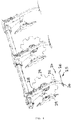
- the wheels 23 of the rear undercarriage axis 7b can be arranged a little behind the rearmost cultivator tines 4, for example the wheel axis can be arranged behind the cultivator tines 4, while a front wheel section with the cultivator tines 4
- the rearmost row of cultivator tines can be arranged to overlap when the device is viewed in the direction of the wheel axis, as is the case here Fig. 3 shows.
- the undercarriage 7 is advantageously designed to be height-adjustable so that the wheels 23 of the undercarriage 7 can be lowered and lifted relative to the machine frame 2.
- the axles of the wheels 23 can be suspended on axle carrier rockers, which can be pivotally mounted on the machine frame 2, so that the wheels can be adjusted up and down by pivoting the axle rockers.
- the undercarriage 7 is adjustable in height
- the tillage position shown in the drawings can be set, in which the cultivator tines 4 run a little way below the ground contact area of the undercarriage 7, so that the height difference between the ground contact area of the undercarriage 7 and the cultivator tines 4 or their lower end section represents the machining depth at least approximately.
- the chassis can also serve as a transport chassis with height adjustability, the chassis 7 being lowered further into the transport position - in comparison to the tillage position shown in the drawings - relative to the machine frame 2, so that the cultivator tines 4 with their lower end sections are sufficiently far above the ground contact area of the chassis 7 come to rest so as not to scratch the ground during road transport.
- the height adjustability of the undercarriage 7 can be designed such that the undercarriage 7 can be brought into an inactive position, in particular if the device is to be supported on the trailer or the trailer unit 5. For this purpose, the undercarriage 7 is then raised further above the tillage position shown in the drawings, so that the device is no longer supported on the undercarriage 7 but on the trailer 5.
- the tillage tools with their intended soil engagement section can be positioned substantially completely under the ground contact area of the undercarriage 7 when the undercarriage 7 is in its tillage position.
- Said cultivator tines 4 can have, in particular, coulter bars or engagement wings as the ground engagement section, which in the said tillage position of the undercarriage 7 lie below its ground contact area, cf. Fig. 3 .
- FIG. 3 shows, viewed in the direction of travel, loosening tools 24 are provided behind the rear chassis axis 7b of the chassis 7, which loosen the soil compacted by the chassis 7 again in the lane of the chassis.
- These loosening tools 24 can only in the lanes of the chassis 7 may be arranged. Alternatively, however, it is also possible to arrange further such loosening tools 24 between the lanes of the chassis 7.
- the loosening tools 24 mentioned are designed differently from the tillage tools which carry out the intended tillage of the attachment 1 according to its intended use.
- the loosening tools 24 can work the soil to a lesser extent and / or introduce less working energy into the soil than the tillage tools attached in front of the chassis axis 7b.
- the loosening tools 24 can have a smaller working depth and / or a smaller, active engaging surface which engages in the ground as intended than the tillage tools leading the chassis axis 7b.
- the said loosening tools 24 can have a smaller working depth and shorter and / or smaller engagement wings.
- Said loosening tools 24 can in particular have loosening tines 25, which comprise a tine body, which preferably points obliquely downwards, the lower end of which engages in the soil in order to loosen the soil.
- the loosening tines 25 can have loosening wings projecting laterally at their lower ends or just above the lower ends or in an end section, for example in the form of wing blades 26, in order to additionally loosen the soil.
- the said loosening wings 26 in the working position of the loosening tines 25, can be inclined at an acute angle to the horizontal, in particular against the direction of travel, rise slightly backwards to loosen up or raise the soil when the loosening wings 26 sail or scratch through the ground.
- the loosening tines 25 are advantageously height-adjustable, advantageously a linear guide 27 can be provided for displaceable guidance of the loosening tines 25.
- a linear guide 27 does not change the angle of attack of the loosening blades 26 when the loosening tines 25 are adjusted in height.
- the linear guide 27 can provide an oblique displacement of the loosening tines 25, wherein a sliding direction 28 or an adjustment direction of the linear guide 27 can be at an angle of, for example, 10 ° to 80 ° to the vertical, in particular approximately 30 ° to 60 ° to the vertical.
- the loosening tines 25 can have a substantially straight guide section which is guided in the linear guide 27 mentioned. Irrespective of this, the loosening tines 25 can have an offset 29 towards their lower end section, through which the tine body extends increasingly steeper towards the bottom towards its lower end section, cf. Fig. 6 .
- the loosening tines 25 can be fixed or blocked in the linear guide 27 in different positions in order to be able to make different height adjustments.
- a hole pattern or recess pattern can be provided in the tine body, into which a bolt, for example in the form of a plug pin, can engage and block the tines.
- the loosening tines 25 can be adjusted in height between a raised non-working position and a lowered working position. In the non-working position, the tines run above the ground and do not engage in it, while in the lowered working position there is an intervention in the ground.
- the loosening tools 24 can also have bottom engagement disks 29, which can in particular be designed as swash plates which are rotatably mounted about an axis of rotation, which axis of rotation is inclined at an acute angle to a horizontal plane and / or to a vertical transverse plane that are vertical extends to the direction of travel, can be inclined at an acute angle.
- said disks 29 can be arranged in pairs and placed at an angle such that they delimit a space that is spread out in a V-shape between them, the main axis of which can extend obliquely backwards upward against the direction of travel, ie the disks of a pair of disks diverge backwards / upwards how this is the Figures 4 and 5 demonstrate.
- Said disks 29 or a corresponding pair of disks can each be assigned to a loosening prong 25, so that a pair of disks each precedes a loosening tine 25.
- the disks 29, which are assigned to a loosening tine 25, can be spaced a little apart from one another, so that the trailing loosening tine 25 runs in a track area between the assigned disks 29.
- the loosening tines 25 can be arranged in their lowered working position with their lower engagement portions approximately at the level of the lower engagement portions of said disks 29. Are the loosening tines 25 raised in their non-working position, cf. Fig. 6 , The engagement portions of the loosening tines 25 are clearly above the lower peripheral portion of said disks 29.
- the loosening tines 25 can thus advantageously be adjusted in height relative to the associated disks 29.
Landscapes
- Life Sciences & Earth Sciences (AREA)
- Engineering & Computer Science (AREA)
- Mechanical Engineering (AREA)
- Soil Sciences (AREA)
- Environmental Sciences (AREA)
- Soil Working Implements (AREA)
Applications Claiming Priority (1)
| Application Number | Priority Date | Filing Date | Title |
|---|---|---|---|
| DE202018105099.0U DE202018105099U1 (de) | 2018-09-06 | 2018-09-06 | Bodenbearbeitungsgerät |
Publications (2)
| Publication Number | Publication Date |
|---|---|
| EP3620037A1 true EP3620037A1 (fr) | 2020-03-11 |
| EP3620037B1 EP3620037B1 (fr) | 2023-08-30 |
Family
ID=67437950
Family Applications (1)
| Application Number | Title | Priority Date | Filing Date |
|---|---|---|---|
| EP19186939.5A Active EP3620037B1 (fr) | 2018-09-06 | 2019-07-18 | Appareil de travail de la terre |
Country Status (2)
| Country | Link |
|---|---|
| EP (1) | EP3620037B1 (fr) |
| DE (1) | DE202018105099U1 (fr) |
Cited By (1)
| Publication number | Priority date | Publication date | Assignee | Title |
|---|---|---|---|---|
| WO2024133083A1 (fr) * | 2022-12-19 | 2024-06-27 | Väderstad Holding Ab | Dispositif de pointe auxiliaire, outil de travail du sol et équipement agricole comprenant un tel outil, dispositif de montage, pointe auxiliaire, procédé de modification et de fonctionnement d'un équipement agricole |
Families Citing this family (1)
| Publication number | Priority date | Publication date | Assignee | Title |
|---|---|---|---|---|
| DE102021117388B4 (de) | 2021-07-06 | 2025-06-05 | Horsch Maschinen Gmbh | Bodenbearbeitungsvorrichtung |
Citations (7)
| Publication number | Priority date | Publication date | Assignee | Title |
|---|---|---|---|---|
| DE2735902A1 (de) * | 1977-06-08 | 1978-12-14 | Werner Ullrich | Spurlockerer |
| DE2945896A1 (de) * | 1979-11-14 | 1981-05-21 | Amazonen-Werke H. Dreyer Gmbh & Co Kg, 4507 Hasbergen | Geraetekombination zur saatbettbereitung |
| CA2223782A1 (fr) * | 1997-12-05 | 1999-06-05 | Darin Hubscher | Cultivateur |
| EP2279652A1 (fr) | 2009-07-27 | 2011-02-02 | Paul Treffler | Cultivateur |
| DE102010000527A1 (de) * | 2010-02-24 | 2011-08-25 | Amazonen-Werke H. Dreyer GmbH & Co. KG, 49205 | Sämaschine |
| WO2017013175A1 (fr) * | 2015-07-21 | 2017-01-26 | Amazonen-Werke H. Dreyer Gmbh & Co. Kg | Semoir |
| DE102016118093A1 (de) * | 2016-09-26 | 2018-03-29 | Amazonen-Werke H. Dreyer Gmbh & Co. Kg | Sämaschine zum Ausbringen von Saatgut und/oder Dünger |
Family Cites Families (2)
| Publication number | Priority date | Publication date | Assignee | Title |
|---|---|---|---|---|
| US3757871A (en) * | 1972-01-26 | 1973-09-11 | Deere & Co | Minimum tillage agricultural implement |
| US4567689A (en) * | 1983-12-30 | 1986-02-04 | Lemons Daniel P | Vineyard cultivator |
-
2018
- 2018-09-06 DE DE202018105099.0U patent/DE202018105099U1/de not_active Expired - Lifetime
-
2019
- 2019-07-18 EP EP19186939.5A patent/EP3620037B1/fr active Active
Patent Citations (7)
| Publication number | Priority date | Publication date | Assignee | Title |
|---|---|---|---|---|
| DE2735902A1 (de) * | 1977-06-08 | 1978-12-14 | Werner Ullrich | Spurlockerer |
| DE2945896A1 (de) * | 1979-11-14 | 1981-05-21 | Amazonen-Werke H. Dreyer Gmbh & Co Kg, 4507 Hasbergen | Geraetekombination zur saatbettbereitung |
| CA2223782A1 (fr) * | 1997-12-05 | 1999-06-05 | Darin Hubscher | Cultivateur |
| EP2279652A1 (fr) | 2009-07-27 | 2011-02-02 | Paul Treffler | Cultivateur |
| DE102010000527A1 (de) * | 2010-02-24 | 2011-08-25 | Amazonen-Werke H. Dreyer GmbH & Co. KG, 49205 | Sämaschine |
| WO2017013175A1 (fr) * | 2015-07-21 | 2017-01-26 | Amazonen-Werke H. Dreyer Gmbh & Co. Kg | Semoir |
| DE102016118093A1 (de) * | 2016-09-26 | 2018-03-29 | Amazonen-Werke H. Dreyer Gmbh & Co. Kg | Sämaschine zum Ausbringen von Saatgut und/oder Dünger |
Cited By (1)
| Publication number | Priority date | Publication date | Assignee | Title |
|---|---|---|---|---|
| WO2024133083A1 (fr) * | 2022-12-19 | 2024-06-27 | Väderstad Holding Ab | Dispositif de pointe auxiliaire, outil de travail du sol et équipement agricole comprenant un tel outil, dispositif de montage, pointe auxiliaire, procédé de modification et de fonctionnement d'un équipement agricole |
Also Published As
| Publication number | Publication date |
|---|---|
| EP3620037B1 (fr) | 2023-08-30 |
| DE202018105099U1 (de) | 2019-12-09 |
Similar Documents
| Publication | Publication Date | Title |
|---|---|---|
| EP2605632B1 (fr) | Machine agricole tractée dotée d'un rouleau | |
| EP0089053B1 (fr) | Machine pour le travail du sol | |
| DE102014107515A1 (de) | Pflug mit mehreren an einem Pflugbalken angebrachten Pflugkörpern | |
| WO2014173388A2 (fr) | Appareil de traitement du sol destiné à être monté sur un véhicule tracteur | |
| DE102017116633A1 (de) | Landwirtschaftliche Bodenbearbeitungsmaschine | |
| EP3620037B1 (fr) | Appareil de travail de la terre | |
| EP3434089B1 (fr) | Machine agricole de traitement du sol | |
| DE202007016639U1 (de) | Reitbodenpflegegerät | |
| EP0211967A1 (fr) | Combinaison d'outils de travail de la terre utilisée en agriculture | |
| EP0350513B1 (fr) | Appareil pour travailler le sol | |
| DE3412962A1 (de) | Traggestell fuer ein landwirtschaftliches geraet | |
| EP3620038A1 (fr) | Cultivateur tracté | |
| EP1731009A1 (fr) | Charrue réversible avec un unité de commande de pression | |
| DE3431796C2 (fr) | ||
| DE2521023A1 (de) | Vielschariger aufsattelpflug | |
| DE102010013470B4 (de) | Vorrichtung zum Verteilen von Saatgut und/oder Dünger | |
| EP2091315B1 (fr) | Appareil de travail du sol ayant une largeur d'action importante | |
| DE3337193C2 (fr) | ||
| EP4298880B1 (fr) | Bras oscillant pour machine agricole | |
| EP2074879B1 (fr) | Engin porteur automoteur | |
| DE2616241C2 (de) | AnhängevoUdrehpflug für neben der Vorfurche fahrende Schlepper | |
| DE102006019032B4 (de) | Einklappbare landwirtschaftliche Bestellkombination | |
| DE2607082A1 (de) | Pflug | |
| DE941698C (de) | Landwirtschaftliches Arbeitsgeraet, insbesondere fuer die Bodenbearbeitung | |
| EP4124217A1 (fr) | Machine agricole de traitement du sol, ainsi que son procédé de stationnement dans une position de stationnement |
Legal Events
| Date | Code | Title | Description |
|---|---|---|---|
| PUAI | Public reference made under article 153(3) epc to a published international application that has entered the european phase |
Free format text: ORIGINAL CODE: 0009012 |
|
| STAA | Information on the status of an ep patent application or granted ep patent |
Free format text: STATUS: THE APPLICATION HAS BEEN PUBLISHED |
|
| AK | Designated contracting states |
Kind code of ref document: A1 Designated state(s): AL AT BE BG CH CY CZ DE DK EE ES FI FR GB GR HR HU IE IS IT LI LT LU LV MC MK MT NL NO PL PT RO RS SE SI SK SM TR |
|
| AX | Request for extension of the european patent |
Extension state: BA ME |
|
| STAA | Information on the status of an ep patent application or granted ep patent |
Free format text: STATUS: REQUEST FOR EXAMINATION WAS MADE |
|
| 17P | Request for examination filed |
Effective date: 20200911 |
|
| RBV | Designated contracting states (corrected) |
Designated state(s): AL AT BE BG CH CY CZ DE DK EE ES FI FR GB GR HR HU IE IS IT LI LT LU LV MC MK MT NL NO PL PT RO RS SE SI SK SM TR |
|
| STAA | Information on the status of an ep patent application or granted ep patent |
Free format text: STATUS: EXAMINATION IS IN PROGRESS |
|
| 17Q | First examination report despatched |
Effective date: 20211220 |
|
| GRAP | Despatch of communication of intention to grant a patent |
Free format text: ORIGINAL CODE: EPIDOSNIGR1 |
|
| STAA | Information on the status of an ep patent application or granted ep patent |
Free format text: STATUS: GRANT OF PATENT IS INTENDED |
|
| INTG | Intention to grant announced |
Effective date: 20230213 |
|
| GRAS | Grant fee paid |
Free format text: ORIGINAL CODE: EPIDOSNIGR3 |
|
| P01 | Opt-out of the competence of the unified patent court (upc) registered |
Effective date: 20230613 |
|
| GRAA | (expected) grant |
Free format text: ORIGINAL CODE: 0009210 |
|
| STAA | Information on the status of an ep patent application or granted ep patent |
Free format text: STATUS: THE PATENT HAS BEEN GRANTED |
|
| AK | Designated contracting states |
Kind code of ref document: B1 Designated state(s): AL AT BE BG CH CY CZ DE DK EE ES FI FR GB GR HR HU IE IS IT LI LT LU LV MC MK MT NL NO PL PT RO RS SE SI SK SM TR |
|
| REG | Reference to a national code |
Ref country code: GB Ref legal event code: FG4D Free format text: NOT ENGLISH |
|
| REG | Reference to a national code |
Ref country code: CH Ref legal event code: EP |
|
| REG | Reference to a national code |
Ref country code: DE Ref legal event code: R096 Ref document number: 502019009119 Country of ref document: DE |
|
| REG | Reference to a national code |
Ref country code: IE Ref legal event code: FG4D Free format text: LANGUAGE OF EP DOCUMENT: GERMAN |
|
| REG | Reference to a national code |
Ref country code: LT Ref legal event code: MG9D Ref country code: SE Ref legal event code: TRGR |
|
| REG | Reference to a national code |
Ref country code: NL Ref legal event code: MP Effective date: 20230830 |
|
| PG25 | Lapsed in a contracting state [announced via postgrant information from national office to epo] |
Ref country code: GR Free format text: LAPSE BECAUSE OF FAILURE TO SUBMIT A TRANSLATION OF THE DESCRIPTION OR TO PAY THE FEE WITHIN THE PRESCRIBED TIME-LIMIT Effective date: 20231201 |
|
| PG25 | Lapsed in a contracting state [announced via postgrant information from national office to epo] |
Ref country code: IS Free format text: LAPSE BECAUSE OF FAILURE TO SUBMIT A TRANSLATION OF THE DESCRIPTION OR TO PAY THE FEE WITHIN THE PRESCRIBED TIME-LIMIT Effective date: 20231230 |
|
| PG25 | Lapsed in a contracting state [announced via postgrant information from national office to epo] |
Ref country code: RS Free format text: LAPSE BECAUSE OF FAILURE TO SUBMIT A TRANSLATION OF THE DESCRIPTION OR TO PAY THE FEE WITHIN THE PRESCRIBED TIME-LIMIT Effective date: 20230830 Ref country code: NO Free format text: LAPSE BECAUSE OF FAILURE TO SUBMIT A TRANSLATION OF THE DESCRIPTION OR TO PAY THE FEE WITHIN THE PRESCRIBED TIME-LIMIT Effective date: 20231130 Ref country code: LV Free format text: LAPSE BECAUSE OF FAILURE TO SUBMIT A TRANSLATION OF THE DESCRIPTION OR TO PAY THE FEE WITHIN THE PRESCRIBED TIME-LIMIT Effective date: 20230830 Ref country code: LT Free format text: LAPSE BECAUSE OF FAILURE TO SUBMIT A TRANSLATION OF THE DESCRIPTION OR TO PAY THE FEE WITHIN THE PRESCRIBED TIME-LIMIT Effective date: 20230830 Ref country code: IS Free format text: LAPSE BECAUSE OF FAILURE TO SUBMIT A TRANSLATION OF THE DESCRIPTION OR TO PAY THE FEE WITHIN THE PRESCRIBED TIME-LIMIT Effective date: 20231230 Ref country code: HR Free format text: LAPSE BECAUSE OF FAILURE TO SUBMIT A TRANSLATION OF THE DESCRIPTION OR TO PAY THE FEE WITHIN THE PRESCRIBED TIME-LIMIT Effective date: 20230830 Ref country code: GR Free format text: LAPSE BECAUSE OF FAILURE TO SUBMIT A TRANSLATION OF THE DESCRIPTION OR TO PAY THE FEE WITHIN THE PRESCRIBED TIME-LIMIT Effective date: 20231201 Ref country code: FI Free format text: LAPSE BECAUSE OF FAILURE TO SUBMIT A TRANSLATION OF THE DESCRIPTION OR TO PAY THE FEE WITHIN THE PRESCRIBED TIME-LIMIT Effective date: 20230830 |
|
| PG25 | Lapsed in a contracting state [announced via postgrant information from national office to epo] |
Ref country code: PL Free format text: LAPSE BECAUSE OF FAILURE TO SUBMIT A TRANSLATION OF THE DESCRIPTION OR TO PAY THE FEE WITHIN THE PRESCRIBED TIME-LIMIT Effective date: 20230830 Ref country code: NL Free format text: LAPSE BECAUSE OF FAILURE TO SUBMIT A TRANSLATION OF THE DESCRIPTION OR TO PAY THE FEE WITHIN THE PRESCRIBED TIME-LIMIT Effective date: 20230830 |
|
| PG25 | Lapsed in a contracting state [announced via postgrant information from national office to epo] |
Ref country code: ES Free format text: LAPSE BECAUSE OF FAILURE TO SUBMIT A TRANSLATION OF THE DESCRIPTION OR TO PAY THE FEE WITHIN THE PRESCRIBED TIME-LIMIT Effective date: 20230830 |
|
| PG25 | Lapsed in a contracting state [announced via postgrant information from national office to epo] |
Ref country code: SM Free format text: LAPSE BECAUSE OF FAILURE TO SUBMIT A TRANSLATION OF THE DESCRIPTION OR TO PAY THE FEE WITHIN THE PRESCRIBED TIME-LIMIT Effective date: 20230830 Ref country code: RO Free format text: LAPSE BECAUSE OF FAILURE TO SUBMIT A TRANSLATION OF THE DESCRIPTION OR TO PAY THE FEE WITHIN THE PRESCRIBED TIME-LIMIT Effective date: 20230830 Ref country code: ES Free format text: LAPSE BECAUSE OF FAILURE TO SUBMIT A TRANSLATION OF THE DESCRIPTION OR TO PAY THE FEE WITHIN THE PRESCRIBED TIME-LIMIT Effective date: 20230830 Ref country code: EE Free format text: LAPSE BECAUSE OF FAILURE TO SUBMIT A TRANSLATION OF THE DESCRIPTION OR TO PAY THE FEE WITHIN THE PRESCRIBED TIME-LIMIT Effective date: 20230830 Ref country code: DK Free format text: LAPSE BECAUSE OF FAILURE TO SUBMIT A TRANSLATION OF THE DESCRIPTION OR TO PAY THE FEE WITHIN THE PRESCRIBED TIME-LIMIT Effective date: 20230830 Ref country code: SK Free format text: LAPSE BECAUSE OF FAILURE TO SUBMIT A TRANSLATION OF THE DESCRIPTION OR TO PAY THE FEE WITHIN THE PRESCRIBED TIME-LIMIT Effective date: 20230830 Ref country code: PT Free format text: LAPSE BECAUSE OF FAILURE TO SUBMIT A TRANSLATION OF THE DESCRIPTION OR TO PAY THE FEE WITHIN THE PRESCRIBED TIME-LIMIT Effective date: 20240102 |
|
| PG25 | Lapsed in a contracting state [announced via postgrant information from national office to epo] |
Ref country code: IT Free format text: LAPSE BECAUSE OF FAILURE TO SUBMIT A TRANSLATION OF THE DESCRIPTION OR TO PAY THE FEE WITHIN THE PRESCRIBED TIME-LIMIT Effective date: 20230830 |
|
| REG | Reference to a national code |
Ref country code: DE Ref legal event code: R097 Ref document number: 502019009119 Country of ref document: DE |
|
| PLBE | No opposition filed within time limit |
Free format text: ORIGINAL CODE: 0009261 |
|
| STAA | Information on the status of an ep patent application or granted ep patent |
Free format text: STATUS: NO OPPOSITION FILED WITHIN TIME LIMIT |
|
| PGFP | Annual fee paid to national office [announced via postgrant information from national office to epo] |
Ref country code: CZ Payment date: 20240611 Year of fee payment: 6 |
|
| PG25 | Lapsed in a contracting state [announced via postgrant information from national office to epo] |
Ref country code: SI Free format text: LAPSE BECAUSE OF FAILURE TO SUBMIT A TRANSLATION OF THE DESCRIPTION OR TO PAY THE FEE WITHIN THE PRESCRIBED TIME-LIMIT Effective date: 20230830 |
|
| 26N | No opposition filed |
Effective date: 20240603 |
|
| PGFP | Annual fee paid to national office [announced via postgrant information from national office to epo] |
Ref country code: DE Payment date: 20240715 Year of fee payment: 6 |
|
| PGFP | Annual fee paid to national office [announced via postgrant information from national office to epo] |
Ref country code: FR Payment date: 20240725 Year of fee payment: 6 |
|
| PGFP | Annual fee paid to national office [announced via postgrant information from national office to epo] |
Ref country code: SE Payment date: 20240725 Year of fee payment: 6 |
|
| PG25 | Lapsed in a contracting state [announced via postgrant information from national office to epo] |
Ref country code: BG Free format text: LAPSE BECAUSE OF FAILURE TO SUBMIT A TRANSLATION OF THE DESCRIPTION OR TO PAY THE FEE WITHIN THE PRESCRIBED TIME-LIMIT Effective date: 20230830 |
|
| PG25 | Lapsed in a contracting state [announced via postgrant information from national office to epo] |
Ref country code: BG Free format text: LAPSE BECAUSE OF FAILURE TO SUBMIT A TRANSLATION OF THE DESCRIPTION OR TO PAY THE FEE WITHIN THE PRESCRIBED TIME-LIMIT Effective date: 20230830 |
|
| PG25 | Lapsed in a contracting state [announced via postgrant information from national office to epo] |
Ref country code: MC Free format text: LAPSE BECAUSE OF FAILURE TO SUBMIT A TRANSLATION OF THE DESCRIPTION OR TO PAY THE FEE WITHIN THE PRESCRIBED TIME-LIMIT Effective date: 20230830 |
|
| REG | Reference to a national code |
Ref country code: CH Ref legal event code: PL |
|
| PG25 | Lapsed in a contracting state [announced via postgrant information from national office to epo] |
Ref country code: LU Free format text: LAPSE BECAUSE OF NON-PAYMENT OF DUE FEES Effective date: 20240718 |
|
| GBPC | Gb: european patent ceased through non-payment of renewal fee |
Effective date: 20240718 |
|
| PG25 | Lapsed in a contracting state [announced via postgrant information from national office to epo] |
Ref country code: LU Free format text: LAPSE BECAUSE OF NON-PAYMENT OF DUE FEES Effective date: 20240718 |
|
| PG25 | Lapsed in a contracting state [announced via postgrant information from national office to epo] |
Ref country code: CH Free format text: LAPSE BECAUSE OF NON-PAYMENT OF DUE FEES Effective date: 20240731 Ref country code: BE Free format text: LAPSE BECAUSE OF NON-PAYMENT OF DUE FEES Effective date: 20240731 |
|
| PG25 | Lapsed in a contracting state [announced via postgrant information from national office to epo] |
Ref country code: GB Free format text: LAPSE BECAUSE OF NON-PAYMENT OF DUE FEES Effective date: 20240718 |
|
| REG | Reference to a national code |
Ref country code: BE Ref legal event code: MM Effective date: 20240731 |
|
| PG25 | Lapsed in a contracting state [announced via postgrant information from national office to epo] |
Ref country code: IE Free format text: LAPSE BECAUSE OF NON-PAYMENT OF DUE FEES Effective date: 20240718 |
|
| REG | Reference to a national code |
Ref country code: AT Ref legal event code: MM01 Ref document number: 1604118 Country of ref document: AT Kind code of ref document: T Effective date: 20240718 |
|
| PG25 | Lapsed in a contracting state [announced via postgrant information from national office to epo] |
Ref country code: AT Free format text: LAPSE BECAUSE OF NON-PAYMENT OF DUE FEES Effective date: 20240718 |
|
| PG25 | Lapsed in a contracting state [announced via postgrant information from national office to epo] |
Ref country code: CY Free format text: LAPSE BECAUSE OF FAILURE TO SUBMIT A TRANSLATION OF THE DESCRIPTION OR TO PAY THE FEE WITHIN THE PRESCRIBED TIME-LIMIT; INVALID AB INITIO Effective date: 20190718 |
|
| REG | Reference to a national code |
Ref country code: DE Ref legal event code: R119 Ref document number: 502019009119 Country of ref document: DE |
|
| PG25 | Lapsed in a contracting state [announced via postgrant information from national office to epo] |
Ref country code: HU Free format text: LAPSE BECAUSE OF FAILURE TO SUBMIT A TRANSLATION OF THE DESCRIPTION OR TO PAY THE FEE WITHIN THE PRESCRIBED TIME-LIMIT; INVALID AB INITIO Effective date: 20190718 |
|
| PG25 | Lapsed in a contracting state [announced via postgrant information from national office to epo] |
Ref country code: DE Free format text: LAPSE BECAUSE OF NON-PAYMENT OF DUE FEES Effective date: 20260203 |
|
| PG25 | Lapsed in a contracting state [announced via postgrant information from national office to epo] |
Ref country code: FR Free format text: LAPSE BECAUSE OF NON-PAYMENT OF DUE FEES Effective date: 20250731 |