EP3620043B1 - Machine de fenaison, en particulier andaineuse rotative - Google Patents
Machine de fenaison, en particulier andaineuse rotative Download PDFInfo
- Publication number
- EP3620043B1 EP3620043B1 EP19195377.7A EP19195377A EP3620043B1 EP 3620043 B1 EP3620043 B1 EP 3620043B1 EP 19195377 A EP19195377 A EP 19195377A EP 3620043 B1 EP3620043 B1 EP 3620043B1
- Authority
- EP
- European Patent Office
- Prior art keywords
- spring
- retaining bracket
- haymaking machine
- rake
- machine according
- Prior art date
- Legal status (The legal status is an assumption and is not a legal conclusion. Google has not performed a legal analysis and makes no representation as to the accuracy of the status listed.)
- Active
Links
Images

Classifications
-
- A—HUMAN NECESSITIES
- A01—AGRICULTURE; FORESTRY; ANIMAL HUSBANDRY; HUNTING; TRAPPING; FISHING
- A01D—HARVESTING; MOWING
- A01D78/00—Haymakers with tines moving with respect to the machine
- A01D78/08—Haymakers with tines moving with respect to the machine with tine-carrying rotary heads or wheels
- A01D78/10—Haymakers with tines moving with respect to the machine with tine-carrying rotary heads or wheels the tines rotating about a substantially vertical axis
- A01D78/1007—Arrangements to facilitate transportation specially adapted therefor
-
- A—HUMAN NECESSITIES
- A01—AGRICULTURE; FORESTRY; ANIMAL HUSBANDRY; HUNTING; TRAPPING; FISHING
- A01D—HARVESTING; MOWING
- A01D78/00—Haymakers with tines moving with respect to the machine
- A01D78/08—Haymakers with tines moving with respect to the machine with tine-carrying rotary heads or wheels
- A01D78/10—Haymakers with tines moving with respect to the machine with tine-carrying rotary heads or wheels the tines rotating about a substantially vertical axis
- A01D78/1021—Telescopic frames
Definitions
- the invention relates to a haymaking machine, in particular a rotary swather, according to the preamble of claim 1.
- Haymaking machines are well known from practice. For example, haymaking machines designed as rakes and tedders are known. The haymaking machine according to the invention is in particular a rotary swather.
- Fig. 1 shows the known structure of a haymaking machine designed as a side rotary swather 10.
- the haymaking machine 10 has a base frame 11 made up of a longitudinal spar 12 and extension arms 13.
- the haymaking machine 10 can be supported on a substrate to be worked on by means of support wheels 14 that engage the base frame 11
- Haymaking machine 10 can be coupled to a towing vehicle via a drawbar 15.
- the haymaking machine 10 designed as a side rotary rake Fig. 1 has raking gyro 16. Each raking gyro 16 is mounted on an extension arm 13 of the haymaking machine 10.
- Each rotary rake 16 of the haymaking machine 10 can be driven around a rotary axis and has tine arms 17 with rake tines 18 Fig. 1
- the haymaking machine 10 shown has two rotary rakes 16, a first rotary rake being positioned on a first side of the longitudinal spar 12 and a second rotary rake 16 on a second, opposite side of the longitudinal spar 12.
- the rear rake gyro 16 is shown in the working position, whereas the front rake gyro 16 is lifted out of a working position.
- the respective rotary rake 16 can be supported on the ground to be worked by means of feeler and support wheels 19. Then, when the respective rake gyro 16 is lifted out of its working position, the feeler and support wheels 19 of the respective rake gyro 16 are lifted from the ground to be worked.
- a haymaking machine 10 designed as a side rotary rake with the in Fig. 1
- the structure shown is from the DE 20 2007 001 281 U1 known.
- each rotary rake 16 of the hay-making machine is mounted on an extension arm 13 of the hay-making machine 10. So it's out of the DE 20 2007 001 281 U1 It is known that the respective rake gyro is mounted on the respective boom arm in such a way that the respective rake gyro is translationally displaceable relative to the respective boom arm via a guide carriage.
- the respective rotary rake of the haymaking machine can be rotationally displaced with respect to the guide carriage, to be precise about two axes running perpendicular to one another.
- a first axis extends parallel to the longitudinal spar in the horizontal direction
- a second axis extends perpendicular to this, likewise in the horizontal direction.
- a rake gyro can roll and pitch movements around these axes and follow the course of the terrain by copying the ground, especially at peaks and valleys.
- the respective rotary rake of the haymaking machine can be pivoted together with the respective extension arm relative to the longitudinal spar in order to transfer the haymaking machine between a working position and a transport position.
- the present invention is based on the object of creating a new type of haymaking machine.
- a first retaining bracket engages the guide carriage of the respective raking gyro.
- a second retaining bracket engages the respective raking top.
- a rod extends through this retaining bracket.
- a first spring and a second spring are guided on the respective rod, the first spring being arranged on a first side of the second holding bracket facing the first holding bracket, and the second spring being arranged on a second side of the second holding bracket facing away from the first holding bracket is.
- the respective rotary rake is held in a predetermined position between the springs.
- the movements of the rake, in particular for ground adaptation, take place against the resulting force of the two interacting springs.
- the maximum deflection of the raking top is achieved when the windings of the compressed spring are in contact with each other.
- the rake does not hit this stop suddenly, but gently.
- the loads acting on the boom during operation are thereby advantageously reduced.
- the respective rotary rake can be set down more quickly with less load on the ground to be worked.
- This mounting of the respective raking gyro on the respective guide carriage via the springs has the advantage in the transport position that the raking gyro cannot move freely between the stops in its folded-up position, but is held in a predetermined intermediate position by the springs.
- the centrifugal or transverse forces that occur dynamically during transport can a rake according to the invention therefore not suddenly move from one stop to the other.
- the loads acting on the boom and on the haymaking machine are advantageously reduced.
- the first spring and the second spring are each a compression spring. This is particularly preferred in order to keep a relative movement between the respective raking gyro and respective guide carriage as low as possible in the transport position and to dampen loads that act on the haymaking machine and keep them as low as possible in the working position and headland position.
- the first spring is supported on a first spring plate facing the second retaining bracket and on a second spring plate facing away from the second retaining bracket.
- the second spring is supported on a third spring plate facing the second retaining bracket and on a fourth spring plate facing away from the second retaining bracket.
- the springs are penetrated by the rod designed as a threaded rod and the second and fourth spring plates are supported by nuts on the threaded rod.
- the distance between the second and fourth spring plates can be changed by the screw-in length of the two nuts, whereby the preload of the springs can be influenced.
- the basic position of the respective rake can also be changed.
- the basic position is the position that the raking top assumes relative to the guide carriage when it is lifted from the ground.
- a section of the threaded rod which extends through the first retaining bracket is fixed to the first retaining bracket by means of nuts which are arranged on opposite sides of the first retaining bracket.
- a basic position of the respective rotary rake, which it assumes in particular in the headland position, can be set via the nuts engaging the first retaining bracket.
- the present invention relates to a haymaking machine.
- the invention is particularly preferably used in a haymaking machine designed as a rotary swather.
- the invention is not limited to use with rotary rakes. Rather, the invention can also be used in other haymaking machines.
- a haymaking machine has a base frame 11 which comprises a longitudinal spar 12 and extension arms 13.
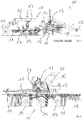
- Fig. 2 , 3 and 4 each show a detail from a haymaking machine according to the invention in the area of a rake gyro 16, which is mounted on an extension arm 13 of a base frame of the haymaking machine.
- Such a rake gyro 16 can be driven around a gyro axis and has tine arms 17 with rake tines 18. Supports itself in the working position the respective rake gyro 16 via feeler and support wheels 19 on a ground to be processed.
- the respective rotary rake 16 of the haymaking machine 10 is mounted on the respective guide carriage 20, the respective rotary rake 16 being translationally displaceable relative to the respective boom 13 via a guide carriage 20 in order to retract and extend the respective rotary rake 16 transversely to the longitudinal direction of the longitudinal spar 12 of the base frame 11 .
- the respective raking top 16 of the haymaking machine 10 can also be rotated relative to the respective guide carriage 20, preferably about two pivot axes 21, 22.
- a first pivot axis 21 extends horizontally and parallel to the guide arm 13 in the working position of the haymaking machine the working position of the haymaking machine 10 is perpendicular to this, also horizontally, but parallel to the longitudinal spar 12.
- a first retaining bracket 23 engages the respective guide carriage 20 of the respective raking gyro 16.
- a second retaining bracket 24 engages the respective raking top 16.
- a rod 25 extends through the two holding brackets 23, 24, namely through free ends of the respective holding brackets 23, 24 facing away from the respective guide carriage 20 or the respective rake gyro 16.
- a first spring 26 and a second spring are located on the respective rod 25 27 led.
- the first spring 26 is arranged on a first side of the second retaining bracket 24 facing the first retaining bracket 23.
- the second spring 27 is arranged on a second side of the second retaining bracket 24 facing away from the first retaining bracket 23.
- the second spring 27 acts counteracts this movement and dampens it.
- the two springs 26 and 27 are compression springs.
- the first spring 26 and the second spring 27 are supported at both ends on spring plates.
- the first spring 26 is supported on a first spring plate 28 facing the second retaining clip 24 and on a second spring plate 29 facing away from the second retaining clip 24.
- the second spring 27 is supported on a third spring plate 30 facing the second retaining clip 24 and on a fourth spring plate 31 facing away from the second retaining clip 24.
- the first spring 26 and the second spring 27 are each pretensioned on the rod 25, namely in that the first spring 26 is tensioned via a first nut 32 which interacts with the threaded rod 25 and which engages the second spring plate 29, whereas the second spring 27 is braced via a second nut 33 which interacts with the rod 25 designed as a threaded rod and which engages the fourth spring plate 31.
- the springs 26, 27 are thus tensioned between the spring plates 29, 31, which are held by the respective nuts 32, 33.
- the bias of the springs 26, 27 can be changed via the distance between the second spring plate 29 and the fourth spring plate 31. This distance can be changed via the screw-in positions of the nuts 32, 33 on the rod 25.
- the rod 25 on which the two compression springs 26 and 27 are arranged extends both through the second retaining bracket 24 and through the first retaining bracket 23.
- the rod 25 slidably extends through a recess in the second retaining bracket 24 . That section of the rod 25 which extends through the first retaining bracket 23 is fixed to the first retaining bracket 23, specifically by means of nuts 34, 35 which are arranged or which act on opposite sides of the first retaining bracket 23. After loosening these nuts 34, 35, a basic position of the respective raking gyro 16, which it assumes in particular in the headland position, can be set.
- the springs 26, 27 designed as compression springs can not only support the movement of the rake gyro 16 about the axis 21, but also a rotational movement Pivoting movement of the rake gyro 16 about the axis 22.
- the two compression springs 26, 27, which provide a double spring arrangement, can dampen forces acting on the rake gyro 16, in particular in the working position. In the transport position, a pivoting movement that the raking gyro 16 can execute relative to the guide carriage 20 is restricted.
- the mounting of the rotary rake 16 on the respective guide carriage 20 via the double spring arrangement of the two compression springs 26, 27 accordingly has advantages both in the working position and in the transport position of the haymaking machine.
- a spherical or spherical or spherical shape can be formed on both sides of the second retaining clip 24, namely the section of the second retaining clip 24 through which the rod 25 extends be positioned arched bearing element (not shown), which allows a tilting movement between the rod 25, the springs 26, 27 and the second bracket 24.
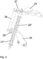
- the Fig. 5 shows a detail of a further embodiment of a haymaking machine according to the invention, in which a shock absorber 36 is arranged parallel to the springs 26 ', 27'.
- brackets 37, 38 are arranged on the retaining brackets 23, 24, to which the joints of the shock absorber 36 are attached. It is of course also possible to provide other fastening options for the shock absorber 36.
- the components not provided with reference symbols correspond to the respective components of the other exemplary embodiments or other figures.
- the shock absorber 36 can be provided to reduce any vibrations that may occur and / or to bring them to a standstill.
- the shock absorber 36 can be designed in correspondingly suitable designs.
- the springs 26, 27, 26 ', 27' can alternatively be designed as gas pressure springs in which the spring force is generated by gas under high pressure.
- Gas springs advantageously require a smaller installation space and A damping mechanism can advantageously be integrated into a gas pressure spring.
- other suitable spring designs can also be provided.
Landscapes
- Life Sciences & Earth Sciences (AREA)
- Environmental Sciences (AREA)
- Soil Working Implements (AREA)
- Jib Cranes (AREA)
Claims (9)
- Machine de fenaison (10), en particulier andaineuse rotative, comprenant
un bâti de base (11) comprenant un longeron (12) ainsi que des bras en porte-à-faux (13), lequel peut être supporté par le biais de roues de support (14) sur un sol à travailler et par le biais duquel la machine de fenaison peut être accouplée à un véhicule tracteur,
au moins une javeleuse circulaire (16) entraînée en rotation autour d'un axe de rotation, laquelle présente des bras porte-dents (17) avec des dents de javeleuse (18), la javeleuse circulaire (16) étant supportée au niveau du bras en porte-à-faux respectif (13) du bâti de base (11) de telle sorte que la javeleuse circulaire respective (16) puisse être déplacée en translation par le biais d'un chariot de guidage (20) par rapport au bras en porte-à-faux respectif (13) et en rotation par rapport au chariot de guidage (20), caractérisée en ce qu'un premier support de fixation (23) vient en prise au niveau du chariot de guidage (20) de la javeleuse circulaire respective (16),
qu'un deuxième support de fixation (24) vient en prise au niveau de la javeleuse circulaire respective (16), qu'une barre (25) s'étend à travers ces supports de fixation (23, 24),
qu'un premier ressort (26) et un deuxième ressort (27) sont guidés au niveau de la barre respective (25),
que le premier ressort (26) est disposé de manière tournée vers le premier support de fixation (23) au niveau d'un premier côté du deuxième support de fixation (24),
que le deuxième ressort (27) est disposé de manière détournée du premier support de fixation (23) au niveau d'un deuxième côté du deuxième support de fixation (24). - Machine de fenaison selon la revendication 1, caractérisée en ce que le premier ressort (26) et le deuxième ressort (27) sont des ressorts de compression.
- Machine de fenaison selon la revendication 1 ou 2, caractérisée en ce que le premier ressort (26) s'appuie sur une première coupelle de ressort (28) tournée vers le deuxième support de fixation (24) et sur une deuxième coupelle de ressort (29) détournée du deuxième support de fixation (24).
- Machine de fenaison selon l'une quelconque des revendications 1 à 3, caractérisée en ce que le deuxième ressort (27) s'appuie sur une troisième coupelle de ressort (30) tournée vers le deuxième support de fixation (24) et sur une quatrième coupelle de ressort (31) détournée du deuxième support de fixation (24).
- Machine de fenaison selon la revendication 4, caractérisée en ce que le premier ressort (26) et le deuxième ressort (27) peuvent être précontraints par le biais d'un premier écrou (32) et/ou par le biais d'un deuxième écrou (33), lesquels coopèrent avec la barre (25) réalisée sous forme de broche filetée.
- Machine de fenaison selon l'une quelconque des revendications 1 à 5, caractérisée en ce qu'une portion de la barre (25) qui s'étend à travers le premier support de fixation (23) est fixée au premier support de fixation (23) .
- Machine de fenaison selon la revendication 6, caractérisée en ce que la portion de la barre (25) qui s'étend à travers le premier support de fixation (23) est fixée au premier support de fixation (23) par le biais d'écrous (34, 35) qui sont disposés sur des côtés opposés du premier support de fixation (23).
- Machine de fenaison selon l'une quelconque des revendications précédentes, caractérisée en ce que les ressorts (26, 27) sont réalisés sous forme de ressorts de compression et/ou sous forme de ressorts de compression à gaz.
- Machine de fenaison selon l'une quelconque des revendications précédentes, caractérisée en ce qu'un pare-chocs (36) est disposé parallèlement aux ressorts (26, 27, 26', 27').
Priority Applications (2)
| Application Number | Priority Date | Filing Date | Title |
|---|---|---|---|
| SI201930083T SI3620043T1 (sl) | 2018-09-07 | 2019-09-04 | Stroj za seno, še zlasti rotacijske grablje |
| PL19195377T PL3620043T3 (pl) | 2018-09-07 | 2019-09-04 | Maszyna do zbioru siana, w szczególności zgrabiarka karuzelowa |
Applications Claiming Priority (1)
| Application Number | Priority Date | Filing Date | Title |
|---|---|---|---|
| DE102018121931.8A DE102018121931A1 (de) | 2018-09-07 | 2018-09-07 | Heuwerbungsmaschine, insbesondere Kreiselschwader |
Publications (2)
| Publication Number | Publication Date |
|---|---|
| EP3620043A1 EP3620043A1 (fr) | 2020-03-11 |
| EP3620043B1 true EP3620043B1 (fr) | 2021-05-05 |
Family
ID=67851036
Family Applications (1)
| Application Number | Title | Priority Date | Filing Date |
|---|---|---|---|
| EP19195377.7A Active EP3620043B1 (fr) | 2018-09-07 | 2019-09-04 | Machine de fenaison, en particulier andaineuse rotative |
Country Status (4)
| Country | Link |
|---|---|
| EP (1) | EP3620043B1 (fr) |
| DE (1) | DE102018121931A1 (fr) |
| PL (1) | PL3620043T3 (fr) |
| SI (1) | SI3620043T1 (fr) |
Families Citing this family (1)
| Publication number | Priority date | Publication date | Assignee | Title |
|---|---|---|---|---|
| DE102023122251A1 (de) * | 2023-08-21 | 2025-02-27 | Claas Saulgau Gmbh | Heuwerbungsmaschine und Verfahren zur Einstellung eines Abstands eines Kreiselkörpers der Heuwerbungsmaschine zu einem Untergrund |
Family Cites Families (6)
| Publication number | Priority date | Publication date | Assignee | Title |
|---|---|---|---|---|
| DE29820227U1 (de) * | 1998-11-12 | 1999-02-11 | Maschinenfabriken Bernard Krone Gmbh, 48480 Spelle | Heuwerbungsmaschine |
| DE102005013054A1 (de) * | 2005-03-18 | 2006-09-21 | Claas Saulgau Gmbh | Kreiselheuer |
| DE202007001281U1 (de) * | 2007-01-23 | 2007-06-14 | Claas Saulgau Gmbh | Heuwerbungsmaschine |
| FR2971669B1 (fr) * | 2011-02-17 | 2014-02-21 | Kuhn Sa | Machine de fenaison |
| NL2014796B1 (en) * | 2015-05-12 | 2017-01-27 | Forage Innovations Bv | Agricultural machine. |
| NL2014827B1 (en) * | 2015-05-19 | 2017-01-31 | Forage Innovations Bv | An agricultural machine and a method for proccesing crop. |
-
2018
- 2018-09-07 DE DE102018121931.8A patent/DE102018121931A1/de not_active Withdrawn
-
2019
- 2019-09-04 EP EP19195377.7A patent/EP3620043B1/fr active Active
- 2019-09-04 PL PL19195377T patent/PL3620043T3/pl unknown
- 2019-09-04 SI SI201930083T patent/SI3620043T1/sl unknown
Also Published As
| Publication number | Publication date |
|---|---|
| SI3620043T1 (sl) | 2021-08-31 |
| EP3620043A1 (fr) | 2020-03-11 |
| PL3620043T3 (pl) | 2021-11-15 |
| DE102018121931A1 (de) | 2020-03-12 |
Similar Documents
| Publication | Publication Date | Title |
|---|---|---|
| EP1970226B1 (fr) | Suspension de roue pour véhicules automobiles | |
| DE102010021481B3 (de) | Fahrzeugsitz | |
| DE69931983T2 (de) | Stabilisator | |
| DE10257480B4 (de) | Energieabsorbierendes Wischersystem für ein Fahrzeug | |
| EP2199121A1 (fr) | Suspension de roue pour véhicules automobiles | |
| EP3159194A1 (fr) | Véhicule équipé de suspension d'essieu | |
| EP1133911A1 (fr) | Dispositif pour récolter les fruits des plantes à tige | |
| EP3620043A1 (fr) | Machine de fenaison, en particulier andaineuse rotative | |
| EP2368416B1 (fr) | Tondeuse autoportée dotée d'un réglage en hauteur | |
| EP3556199B1 (fr) | Machine de fenaison agricole | |
| EP2661952A1 (fr) | Machine de fenaison | |
| DE4202771C2 (de) | Überlastsicherung von Bodenbearbeitungsmaschinen | |
| DE69708464T2 (de) | Landwirtschaftliche Maschine | |
| DE102018207616B4 (de) | Radaufhängung für ein Kraftfahrzeug | |
| DE102020113947A1 (de) | Radaufhängung für eine Fahrzeug-Hinterachse | |
| EP3991530B1 (fr) | Véhicule utilitaire agricole doté d'un stabilisateur latéral | |
| EP0566033A1 (fr) | Cadre support pour machine de récolte, en particulier faucheuse rotative | |
| WO1999058354A1 (fr) | Suspension d'essieu pour essieux rigides de vehicules | |
| DE102009053125A1 (de) | Einrichtung zur aktiven Höhenverstellung einer Karosserie eines Fahrzeuges | |
| EP3781418A1 (fr) | Support de rue pour un véhicule à moteur | |
| EP3935930A1 (fr) | Agencement de palier pour un stabilisateur latéral d'un relevage arrière | |
| EP4151790B1 (fr) | Entraînement de barre à passettes d'un métier à tricoter en chaîne | |
| DE102005032610B4 (de) | Blattfederaufhängung für Nutzfahrzeuge | |
| EP3756436B1 (fr) | Relevage avant ainsi que machine de travail doté d'un relevage avant | |
| DE4027025A1 (de) | Heuwerbungsmaschine |
Legal Events
| Date | Code | Title | Description |
|---|---|---|---|
| PUAI | Public reference made under article 153(3) epc to a published international application that has entered the european phase |
Free format text: ORIGINAL CODE: 0009012 |
|
| STAA | Information on the status of an ep patent application or granted ep patent |
Free format text: STATUS: THE APPLICATION HAS BEEN PUBLISHED |
|
| AK | Designated contracting states |
Kind code of ref document: A1 Designated state(s): AL AT BE BG CH CY CZ DE DK EE ES FI FR GB GR HR HU IE IS IT LI LT LU LV MC MK MT NL NO PL PT RO RS SE SI SK SM TR |
|
| AX | Request for extension of the european patent |
Extension state: BA ME |
|
| STAA | Information on the status of an ep patent application or granted ep patent |
Free format text: STATUS: REQUEST FOR EXAMINATION WAS MADE |
|
| 17P | Request for examination filed |
Effective date: 20200911 |
|
| RBV | Designated contracting states (corrected) |
Designated state(s): AL AT BE BG CH CY CZ DE DK EE ES FI FR GB GR HR HU IE IS IT LI LT LU LV MC MK MT NL NO PL PT RO RS SE SI SK SM TR |
|
| GRAP | Despatch of communication of intention to grant a patent |
Free format text: ORIGINAL CODE: EPIDOSNIGR1 |
|
| STAA | Information on the status of an ep patent application or granted ep patent |
Free format text: STATUS: GRANT OF PATENT IS INTENDED |
|
| INTG | Intention to grant announced |
Effective date: 20210205 |
|
| GRAS | Grant fee paid |
Free format text: ORIGINAL CODE: EPIDOSNIGR3 |
|
| GRAA | (expected) grant |
Free format text: ORIGINAL CODE: 0009210 |
|
| STAA | Information on the status of an ep patent application or granted ep patent |
Free format text: STATUS: THE PATENT HAS BEEN GRANTED |
|
| AK | Designated contracting states |
Kind code of ref document: B1 Designated state(s): AL AT BE BG CH CY CZ DE DK EE ES FI FR GB GR HR HU IE IS IT LI LT LU LV MC MK MT NL NO PL PT RO RS SE SI SK SM TR |
|
| REG | Reference to a national code |
Ref country code: GB Ref legal event code: FG4D Free format text: NOT ENGLISH |
|
| REG | Reference to a national code |
Ref country code: CH Ref legal event code: EP |
|
| REG | Reference to a national code |
Ref country code: AT Ref legal event code: REF Ref document number: 1388642 Country of ref document: AT Kind code of ref document: T Effective date: 20210515 |
|
| REG | Reference to a national code |
Ref country code: DE Ref legal event code: R096 Ref document number: 502019001362 Country of ref document: DE |
|
| REG | Reference to a national code |
Ref country code: IE Ref legal event code: FG4D Free format text: LANGUAGE OF EP DOCUMENT: GERMAN |
|
| REG | Reference to a national code |
Ref country code: LT Ref legal event code: MG9D |
|
| PG25 | Lapsed in a contracting state [announced via postgrant information from national office to epo] |
Ref country code: FI Free format text: LAPSE BECAUSE OF FAILURE TO SUBMIT A TRANSLATION OF THE DESCRIPTION OR TO PAY THE FEE WITHIN THE PRESCRIBED TIME-LIMIT Effective date: 20210505 Ref country code: HR Free format text: LAPSE BECAUSE OF FAILURE TO SUBMIT A TRANSLATION OF THE DESCRIPTION OR TO PAY THE FEE WITHIN THE PRESCRIBED TIME-LIMIT Effective date: 20210505 Ref country code: LT Free format text: LAPSE BECAUSE OF FAILURE TO SUBMIT A TRANSLATION OF THE DESCRIPTION OR TO PAY THE FEE WITHIN THE PRESCRIBED TIME-LIMIT Effective date: 20210505 Ref country code: BG Free format text: LAPSE BECAUSE OF FAILURE TO SUBMIT A TRANSLATION OF THE DESCRIPTION OR TO PAY THE FEE WITHIN THE PRESCRIBED TIME-LIMIT Effective date: 20210805 |
|
| PG25 | Lapsed in a contracting state [announced via postgrant information from national office to epo] |
Ref country code: LV Free format text: LAPSE BECAUSE OF FAILURE TO SUBMIT A TRANSLATION OF THE DESCRIPTION OR TO PAY THE FEE WITHIN THE PRESCRIBED TIME-LIMIT Effective date: 20210505 Ref country code: NO Free format text: LAPSE BECAUSE OF FAILURE TO SUBMIT A TRANSLATION OF THE DESCRIPTION OR TO PAY THE FEE WITHIN THE PRESCRIBED TIME-LIMIT Effective date: 20210805 Ref country code: SE Free format text: LAPSE BECAUSE OF FAILURE TO SUBMIT A TRANSLATION OF THE DESCRIPTION OR TO PAY THE FEE WITHIN THE PRESCRIBED TIME-LIMIT Effective date: 20210505 Ref country code: PT Free format text: LAPSE BECAUSE OF FAILURE TO SUBMIT A TRANSLATION OF THE DESCRIPTION OR TO PAY THE FEE WITHIN THE PRESCRIBED TIME-LIMIT Effective date: 20210906 Ref country code: RS Free format text: LAPSE BECAUSE OF FAILURE TO SUBMIT A TRANSLATION OF THE DESCRIPTION OR TO PAY THE FEE WITHIN THE PRESCRIBED TIME-LIMIT Effective date: 20210505 Ref country code: IS Free format text: LAPSE BECAUSE OF FAILURE TO SUBMIT A TRANSLATION OF THE DESCRIPTION OR TO PAY THE FEE WITHIN THE PRESCRIBED TIME-LIMIT Effective date: 20210905 Ref country code: GR Free format text: LAPSE BECAUSE OF FAILURE TO SUBMIT A TRANSLATION OF THE DESCRIPTION OR TO PAY THE FEE WITHIN THE PRESCRIBED TIME-LIMIT Effective date: 20210806 |
|
| REG | Reference to a national code |
Ref country code: NL Ref legal event code: MP Effective date: 20210505 |
|
| PG25 | Lapsed in a contracting state [announced via postgrant information from national office to epo] |
Ref country code: NL Free format text: LAPSE BECAUSE OF FAILURE TO SUBMIT A TRANSLATION OF THE DESCRIPTION OR TO PAY THE FEE WITHIN THE PRESCRIBED TIME-LIMIT Effective date: 20210505 |
|
| PG25 | Lapsed in a contracting state [announced via postgrant information from national office to epo] |
Ref country code: RO Free format text: LAPSE BECAUSE OF FAILURE TO SUBMIT A TRANSLATION OF THE DESCRIPTION OR TO PAY THE FEE WITHIN THE PRESCRIBED TIME-LIMIT Effective date: 20210505 Ref country code: SM Free format text: LAPSE BECAUSE OF FAILURE TO SUBMIT A TRANSLATION OF THE DESCRIPTION OR TO PAY THE FEE WITHIN THE PRESCRIBED TIME-LIMIT Effective date: 20210505 Ref country code: CZ Free format text: LAPSE BECAUSE OF FAILURE TO SUBMIT A TRANSLATION OF THE DESCRIPTION OR TO PAY THE FEE WITHIN THE PRESCRIBED TIME-LIMIT Effective date: 20210505 Ref country code: DK Free format text: LAPSE BECAUSE OF FAILURE TO SUBMIT A TRANSLATION OF THE DESCRIPTION OR TO PAY THE FEE WITHIN THE PRESCRIBED TIME-LIMIT Effective date: 20210505 Ref country code: SK Free format text: LAPSE BECAUSE OF FAILURE TO SUBMIT A TRANSLATION OF THE DESCRIPTION OR TO PAY THE FEE WITHIN THE PRESCRIBED TIME-LIMIT Effective date: 20210505 Ref country code: ES Free format text: LAPSE BECAUSE OF FAILURE TO SUBMIT A TRANSLATION OF THE DESCRIPTION OR TO PAY THE FEE WITHIN THE PRESCRIBED TIME-LIMIT Effective date: 20210505 Ref country code: EE Free format text: LAPSE BECAUSE OF FAILURE TO SUBMIT A TRANSLATION OF THE DESCRIPTION OR TO PAY THE FEE WITHIN THE PRESCRIBED TIME-LIMIT Effective date: 20210505 |
|
| REG | Reference to a national code |
Ref country code: DE Ref legal event code: R097 Ref document number: 502019001362 Country of ref document: DE |
|
| PLBE | No opposition filed within time limit |
Free format text: ORIGINAL CODE: 0009261 |
|
| STAA | Information on the status of an ep patent application or granted ep patent |
Free format text: STATUS: NO OPPOSITION FILED WITHIN TIME LIMIT |
|
| 26N | No opposition filed |
Effective date: 20220208 |
|
| REG | Reference to a national code |
Ref country code: BE Ref legal event code: MM Effective date: 20210930 |
|
| PG25 | Lapsed in a contracting state [announced via postgrant information from national office to epo] |
Ref country code: IS Free format text: LAPSE BECAUSE OF FAILURE TO SUBMIT A TRANSLATION OF THE DESCRIPTION OR TO PAY THE FEE WITHIN THE PRESCRIBED TIME-LIMIT Effective date: 20210905 Ref country code: MC Free format text: LAPSE BECAUSE OF FAILURE TO SUBMIT A TRANSLATION OF THE DESCRIPTION OR TO PAY THE FEE WITHIN THE PRESCRIBED TIME-LIMIT Effective date: 20210505 Ref country code: AL Free format text: LAPSE BECAUSE OF FAILURE TO SUBMIT A TRANSLATION OF THE DESCRIPTION OR TO PAY THE FEE WITHIN THE PRESCRIBED TIME-LIMIT Effective date: 20210505 |
|
| PG25 | Lapsed in a contracting state [announced via postgrant information from national office to epo] |
Ref country code: LU Free format text: LAPSE BECAUSE OF NON-PAYMENT OF DUE FEES Effective date: 20210904 Ref country code: IT Free format text: LAPSE BECAUSE OF FAILURE TO SUBMIT A TRANSLATION OF THE DESCRIPTION OR TO PAY THE FEE WITHIN THE PRESCRIBED TIME-LIMIT Effective date: 20210505 Ref country code: BE Free format text: LAPSE BECAUSE OF NON-PAYMENT OF DUE FEES Effective date: 20210930 |
|
| REG | Reference to a national code |
Ref country code: CH Ref legal event code: PL |
|
| P01 | Opt-out of the competence of the unified patent court (upc) registered |
Effective date: 20230508 |
|
| PG25 | Lapsed in a contracting state [announced via postgrant information from national office to epo] |
Ref country code: CY Free format text: LAPSE BECAUSE OF FAILURE TO SUBMIT A TRANSLATION OF THE DESCRIPTION OR TO PAY THE FEE WITHIN THE PRESCRIBED TIME-LIMIT Effective date: 20210505 |
|
| PG25 | Lapsed in a contracting state [announced via postgrant information from national office to epo] |
Ref country code: LI Free format text: LAPSE BECAUSE OF NON-PAYMENT OF DUE FEES Effective date: 20220930 Ref country code: HU Free format text: LAPSE BECAUSE OF FAILURE TO SUBMIT A TRANSLATION OF THE DESCRIPTION OR TO PAY THE FEE WITHIN THE PRESCRIBED TIME-LIMIT; INVALID AB INITIO Effective date: 20190904 Ref country code: CH Free format text: LAPSE BECAUSE OF NON-PAYMENT OF DUE FEES Effective date: 20220930 |
|
| PG25 | Lapsed in a contracting state [announced via postgrant information from national office to epo] |
Ref country code: MK Free format text: LAPSE BECAUSE OF FAILURE TO SUBMIT A TRANSLATION OF THE DESCRIPTION OR TO PAY THE FEE WITHIN THE PRESCRIBED TIME-LIMIT Effective date: 20210505 |
|
| GBPC | Gb: european patent ceased through non-payment of renewal fee |
Effective date: 20230904 |
|
| PG25 | Lapsed in a contracting state [announced via postgrant information from national office to epo] |
Ref country code: GB Free format text: LAPSE BECAUSE OF NON-PAYMENT OF DUE FEES Effective date: 20230904 |
|
| PG25 | Lapsed in a contracting state [announced via postgrant information from national office to epo] |
Ref country code: GB Free format text: LAPSE BECAUSE OF NON-PAYMENT OF DUE FEES Effective date: 20230904 |
|
| PG25 | Lapsed in a contracting state [announced via postgrant information from national office to epo] |
Ref country code: MT Free format text: LAPSE BECAUSE OF FAILURE TO SUBMIT A TRANSLATION OF THE DESCRIPTION OR TO PAY THE FEE WITHIN THE PRESCRIBED TIME-LIMIT Effective date: 20210505 |
|
| PGFP | Annual fee paid to national office [announced via postgrant information from national office to epo] |
Ref country code: DE Payment date: 20250919 Year of fee payment: 7 |
|
| PGFP | Annual fee paid to national office [announced via postgrant information from national office to epo] |
Ref country code: PL Payment date: 20250821 Year of fee payment: 7 |
|
| PGFP | Annual fee paid to national office [announced via postgrant information from national office to epo] |
Ref country code: FR Payment date: 20250922 Year of fee payment: 7 Ref country code: AT Payment date: 20250919 Year of fee payment: 7 |
|
| PGFP | Annual fee paid to national office [announced via postgrant information from national office to epo] |
Ref country code: IE Payment date: 20250918 Year of fee payment: 7 |
|
| PGFP | Annual fee paid to national office [announced via postgrant information from national office to epo] |
Ref country code: SI Payment date: 20250821 Year of fee payment: 7 |
|
| PG25 | Lapsed in a contracting state [announced via postgrant information from national office to epo] |
Ref country code: TR Free format text: LAPSE BECAUSE OF FAILURE TO SUBMIT A TRANSLATION OF THE DESCRIPTION OR TO PAY THE FEE WITHIN THE PRESCRIBED TIME-LIMIT Effective date: 20210505 |