EP3620180A1 - Machine de désinfection/stérilisation pour des appareils médicaux tels que des endoscopes - Google Patents
Machine de désinfection/stérilisation pour des appareils médicaux tels que des endoscopes Download PDFInfo
- Publication number
- EP3620180A1 EP3620180A1 EP18306181.1A EP18306181A EP3620180A1 EP 3620180 A1 EP3620180 A1 EP 3620180A1 EP 18306181 A EP18306181 A EP 18306181A EP 3620180 A1 EP3620180 A1 EP 3620180A1
- Authority
- EP
- European Patent Office
- Prior art keywords
- opening
- tank
- tunnel
- seal
- assembly
- Prior art date
- Legal status (The legal status is an assumption and is not a legal conclusion. Google has not performed a legal analysis and makes no representation as to the accuracy of the status listed.)
- Granted
Links
Images

Classifications
-
- A—HUMAN NECESSITIES
- A61—MEDICAL OR VETERINARY SCIENCE; HYGIENE
- A61L—METHODS OR APPARATUS FOR STERILISING MATERIALS OR OBJECTS IN GENERAL; DISINFECTION, STERILISATION OR DEODORISATION OF AIR; CHEMICAL ASPECTS OF BANDAGES, DRESSINGS, ABSORBENT PADS OR SURGICAL ARTICLES; MATERIALS FOR BANDAGES, DRESSINGS, ABSORBENT PADS OR SURGICAL ARTICLES
- A61L2/00—Disinfection or sterilisation of materials or objects, in general; Accessories therefor
- A61L2/16—Disinfection or sterilisation of materials or objects, in general; Accessories therefor using chemical substances
- A61L2/18—Liquid substances
-
- A—HUMAN NECESSITIES
- A61—MEDICAL OR VETERINARY SCIENCE; HYGIENE
- A61B—DIAGNOSIS; SURGERY; IDENTIFICATION
- A61B1/00—Instruments for performing medical examinations of the interior of cavities or tubes of the body by visual or photographical inspection, e.g. endoscopes; Illuminating arrangements therefor
- A61B1/12—Instruments for performing medical examinations of the interior of cavities or tubes of the body by visual or photographical inspection, e.g. endoscopes; Illuminating arrangements therefor with cooling or rinsing arrangements
- A61B1/121—Instruments for performing medical examinations of the interior of cavities or tubes of the body by visual or photographical inspection, e.g. endoscopes; Illuminating arrangements therefor with cooling or rinsing arrangements provided with means for cleaning post-use
- A61B1/123—Instruments for performing medical examinations of the interior of cavities or tubes of the body by visual or photographical inspection, e.g. endoscopes; Illuminating arrangements therefor with cooling or rinsing arrangements provided with means for cleaning post-use using washing machines
-
- A—HUMAN NECESSITIES
- A61—MEDICAL OR VETERINARY SCIENCE; HYGIENE
- A61B—DIAGNOSIS; SURGERY; IDENTIFICATION
- A61B90/00—Instruments, implements or accessories specially adapted for surgery or diagnosis and not covered by any of the groups A61B1/00 - A61B50/00, e.g. for luxation treatment or for protecting wound edges
- A61B90/70—Cleaning devices specially adapted for surgical instruments
- A61B2090/701—Cleaning devices specially adapted for surgical instruments for flexible tubular instruments, e.g. endoscopes
-
- A—HUMAN NECESSITIES
- A61—MEDICAL OR VETERINARY SCIENCE; HYGIENE
- A61L—METHODS OR APPARATUS FOR STERILISING MATERIALS OR OBJECTS IN GENERAL; DISINFECTION, STERILISATION OR DEODORISATION OF AIR; CHEMICAL ASPECTS OF BANDAGES, DRESSINGS, ABSORBENT PADS OR SURGICAL ARTICLES; MATERIALS FOR BANDAGES, DRESSINGS, ABSORBENT PADS OR SURGICAL ARTICLES
- A61L2103/00—Materials or objects being the target of disinfection or sterilisation
- A61L2103/15—Laboratory, medical or dentistry appliances, e.g. catheters or sharps
Definitions
- the invention relates to a disinfecting/sterilizing machine for disinfecting/sterilizing medicals apparatus such as endoscopes, and also an installation comprising a wall separating two rooms such as a clean room and a dirty room, said installation comprising a machine for disinfecting/sterilizing medicals apparatus according to invention disposed through an opening of said wall.
- the field of the invention relates to the technical sector of machines relating to the disinfecting/sterilizing of rigid or flexible endoscopes. More particularly the invention relates to such machines that are configured to be disposed through an opening of a wall separating a clean room and a service room.
- the clean room is usually of clean controlled atmosphere, typically under slight over pressure,
- a used endoscope can be inserted into the disinfecting/sterilizing chamber of the machine from the service room so that a cleaning cycle is implemented in said disinfecting/sterilizing chamber. Once the cleaning cycle is completed, the cleaned endoscope can be extracted from the other side of the wall, that is to say from the clean room.
- a first type of pass through disinfecting/sterilizing machine for disinfecting endoscopes which comprises : a frame; a casing covering the frame so as to define a tunnel having a first opening and a second opening which is opposite from the first opening, an upper wall superiorly delimiting the tunnel and a bottom wall inferiorly delimitating the tunnel.
- a first door is hinged to the frame and configured to obstruct the first opening of said tunnel when closed, and a second door is hinged to the frame and configured to obstruct the second opening of the tunnel when closed.
- a basket is dimensioned so as to receive one or more endoscopes to be disinfected/sterilized, and which is dimensioned so as to transit along the tunnel.
- the casing of the machine is installed in an air tight manner in an opening of a wall separating a clean room from a service room. Clean room atmosphere is controlled, typically under slight over pressure.
- Endoscopes are typically arranged in the basket from the service room (dirty room), the basket carrying the endoscope being inserted into the tunnel through the first opening.
- the first door is then closed to implement a cleaning cycle in the disinfecting chamber. During this cycle, cleaning liquids are drawn from canisters by pumps, said pumped liquids being conveyed into the disinfecting chamber to clean the outer surfaces and the inner surfaces of endoscope.
- the second door is opened so that the basket carrying the endoscope is extracted through the second opening: the cleaned endoscope is extracted from the clean room.
- a drawback of such disinfecting/sterilizing machine is the particular large size thereof, this size being mainly due to the dimensions of the chamber receiving the basket whose dimensions cannot be reduced under a certain limit as the basket and the endoscope in turn occupy a certain volume.
- WO 2014/083524 A1 discloses a second type of pass through disinfecting/sterilizing machine that does not require a basket to carry the endoscope.
- the disinfecting/sterilizing machine disclosed in EP disinfecting/sterilising comprises a tunnel having a first opening and a second opening; an upper wall which delimits the tunnel ; a first lateral wall positionable at the first opening such as to obstruct the tunnel; a second lateral wall positionable at the second opening such as to obstruct the tunnel; a bath for receiving an endoscope to be disinfected/sterilised; a bath support; guide means for guiding the group comprising the bath support and the bath along the tunnel between; a first endrun in which the bath projects externally from the first opening of the tunnel such as to be accessible for inserting or extracting the endoscope; and a second endrun in which the bath projects externally from the second opening of the tunnel such as to be accessible such as to insert or extract endoscope.
- the upper wall forms, with said bath, a closed chamber such as to disinfect/sterilize the at least an endoscope when the bath is internal of the tunnel.
- the first lateral wall when at the first opening, is couplable alternatively and removably, with the frame, such as to be solidly constrained to the frame and obstruct the tunnel, or with the bath support such as to be solidly constrained to and be drawn by the group and enable the group to reach the first endrun.
- the second lateral wall when at the second opening, is alternatively and removably couplable; with the frame, such as to be solidly constrained to the frame and obstruct the tunnel, or with the bath support such as to be solidly constrained to and be drawn by the group and enable the group to reach the second endrun.
- cleaning means when the bath is inside the tunnel, cleaning means are activated to wash and disinfect/sterilize the endoscope contained in the chamber.
- Cleaning means comprise hydraulic circuit which opens in the bath, and a final expulsion through as discharge of the bath.
- a cleaning cycle can be implemented causing cleaning liquids such as detergents to flow into the bath, with a final expulsion to the discharge.
- flexible pipes are mandatory to convey cleaning solution such as detergent from the canister to said bath, because the canister are housed in the casing and of a fixed position.
- the travel between first end-run and second end run is necessarily large, corresponding at least as twice the length of said bath in the sliding direction. Therefore, the flexibles pipe joining the canister and the bath must be of an overabundant length so that said flexibles pipes do not interfere with such a large displacement.
- such overabundant length of said flexible pipe makes it very difficult to mechanically guide said flexible pipes when the bath support is displaced from first end-run to second end run (and vice versa). For instance, and according to inventors, the travel is too large to use guide-chain to provide a proper guiding of the flexible pipe(s) during this displacement of the bath group.
- a second drawback inherent to the machined disclosed in WO 2014/083524 A1 is that the first lateral wall (resp. second lateral wall), when at the first opening (resp. second opening), is couplable alternatively and removably: with the frame, such as to be solidly constrained to the frame and obstruct the tunnel, or with the bath support such as to be solidly constrained to and be drawn by the group and enable the group to reach the first endrun (resp. second endrun).
- An operator who is in the service room needs to act on the first handle to removably couple the first lateral wall to the frame or to the bath support.
- an operator who is in the theater room needs to act on second handle so as to removably couple the second lateral wall to the frame or to the bath support.
- At least one of said first lateral wall (resp. said second lateral) must be coupled to the frame to obstruct in an air tight manner said first opening (reps. said second lateral) wall when said second wall (resp. first wall) is moved with said bath group.
- first and second lateral wall needs a complex mechanism to couple them alternatively and removably with the frame or with the bath group.
- complex mechanisms are at the expense of the reliability: each time it is necessary to give access for inserting or extracting an endoscope from the clean room and the dirty room, the bath group must be slid up to first end-run, or upsecond end-run, (and vice versa), and thus, necessary to change the coupling of the first lateral wall (from bath group and frame, or vice versa), and/or the coupling of the second lateral wall (from bath group and frame, or vice versa)
- a third type of pass through disinfecting machine from WASSENBURG® which reference is WD440 PT.
- Such machine comprises a frame, a casing and a bath (or cleaning tank) which is of a fixed position relatively to the frame and casing.
- Access to the bath in order to insert or extract an endoscope from the service room (“ dirty room ”) and access to the bath in in order to insert or extract an endoscope from the theater room (“ clean room ”) is enabled thanks to a tilting lid that is configured to take three positions :
- a main drawback of this design is that the very same underneath surface of the lid passes from the dirty atmosphere of the service room when tilted in first tilted position (to give access to the bath in order to insert or extract an endoscope from the dirty room), to the clean atmosphere of the theater room when tilted in second tilted position (to give access to the bath in order to insert or extract an endoscope from the clean room).
- the fact that this underneath surface of the lid passes from the atmosphere of the dirty room to the atmosphere of the clean room can lead to cross contamination between the two rooms.
- the central zone of the underneath surface of the lid forms an upper surface of the disinfecting chamber, and thus is disinfected by detergent during the implementation of a cleaning cycle, it remains a peripheral zone of said underneath surface of the lid which is not subjected to detergent during the cleaning cycle .
- This peripheral zone can be soiled during the insertion of a dirty endoscope, from the service room, and be tilted in a position wherein this soiled peripheral zone is in said clean room, without being disinfected by a cleaning cycle.
- the present invention aims to improve the situation described above.
- One of the objects of the present invention is to propose a disinfecting/sterilizing machine for disinfecting/sterilizing medicals apparatus that limits the risk of deterioration of a flexible pipe conveying cleaning solution to the bath, compared to disinfecting machine of WO 2014/083524 A1 .
- Another aim of the invention is to propose a pass through disinfecting machine of a simpler design than the one of WO 2014/083524 A1 which guarantees long-term reliability.
- Another aim of the invention is to propose a pass through disinfecting machine which will not cause problem of cross contamination between the dirty room and the clean room as described above.
- a disinfecting/sterilizing machine for disinfecting/sterilizing medicals apparatus such as rigid or flexible endoscopes, comprising:
- the disinfecting/sterilizing machine is of pass-through type and can be positioned in air tight manner in an opening of a wall separating a service room (" dirty room ”) from a theater room (“clean room” ).
- the second opening of the tunnel closed by the lid is positioned in the service room while the first opening is oriented so that the tank assembly projects from said first opening in the clean room in said first position.
- An operator can insert an endoscope to be cleaned in said tank, through said second opening in the upper wall in said second opened position of the lid.
- a cleaning cycle can be implemented, for example by drawing cleaning liquids into the cavity of the tank. Once this cleaning cycle is completed, the tank assembly is slid from second position inside said tunnel up to first position wherein the tank projects from the first opening into the clean room, giving access so that the cleaned endoscope can be extracted from the tank.
- the casing can comprise a fixed compartment receiving one or a plurality of canisters comprising disinfecting/sterilizing liquids, said machine comprising at least a cleaning circuit comprising a flexible pipe, and a pump, said circuit being configured to draw the cleaning liquid from the canister and to convey the liquid into the cavity of the tank in order to clean internal and/or external surfaces of the medical apparatus.
- One or a plurality of flexible pipe(s) joining the canister to the tank assembly are of an overabundant length so that the tank assembly is slideable from first end position to second end position, the flexible pipe not interfering with such a displacement.
- the total travel of the tank assembly necessary to pass from said second position of the tank assembly, inside said tunnel, to said first position is of the order of the length of the tank assembly in the direction of the slides, that is to say around half of the travel necessary for the bath group to pass from first end run to said second end run in the machine according to document WO 2014/083524 A1 .
- Such a reduced length travel makes it possible to guide properly the flexible pipe, by example using handling chain, and contrary to document WO 2014/083524 A1 .
- said movable lid comprises said cover body which is hinged to the casing so as to be displaced from said first closed position to said second open position.
- Said first closed position of the cover body may be locked, for instance using an electromagnetic lock.
- a programmable controller of the machine controls the electromagnetic lock so that said cover body stay locked when a cleaning cycle is implemented.
- a gas pressurized cylinder may be provided between the cover body and the frame/casing so that said pressurized cylinder automatically raises the cover body from said first closed position to second open position.
- said tank assembly comprises a lateral wall fixedly securely to said tank assembly so as to be movable with the tank assembly and configured to obstruct said first opening wherein said tank assembly is inside the tunnel at second end position.
- a gasket (no shown) can be provide between said lateral wall and said first opening to makes sure said first opening is closed in an air tight manner when the tank assembly is in said first position. This provision prevents cross contamination, when the lid is opened, by forbidding air ingress through the casing from the dirty room up to the clean room, and vice versa.
- said movable lid comprises - apart from said cover body - a seal device comprising a seal assembly with a seal plate and a gasket disposed along a periphery of the seal plate.
- the seal device is configured, in said first closed position of the lid, to seal in an fluid tight manner said upper tank opening, in at least one state of the seal device: therefore the internal surface of said cavity and the underneath surface of said seal plate defines a fluid tight sterilizing/disinfecting chamber.
- the cleaning cycle may be implemented by the pump(s) so that cleaning liquid flowing from the canister is conveyed into the sterilizing/disinfecting chamber to clean the internal and/or the external surface of the medical apparatus.
- a programmable controller of the machine is programmed so that the seal device first seals in a fluid tight manner the disinfecting chamber, and before the cleaning liquid is brought into the disinfecting chamber by the pump(s).
- said seal device comprises an actuator joining said seal plate and the cover body, configured, in said first closed position of said lid, to move the seal assembly between two positions, namely :
- said actuator may be a pneumatic actuator, or an electric cylinder.
- said programmable controller controls said actuator so that said seal assembly is moved from downward position to said upward position, before allowing the sliding of said tank assembly from first second to first position, for example by controlling a second actuator configured to displace the tank assembly.
- said gasket in said upward position of the seal assembly, is configured to seal in an air tight manner the upper wall with the seal plate in order to obstruct said second opening in an air tight manner, in at least one state of the gasket: such advantageous provision prevents air ingress between the two rooms through the casing (in particularly from the dirty room up to the clean room) when the tank assembly slides from said second position to said first position, and that said lateral wall does not obstruct anymore first opening.
- the gasket may be provided on an edge of the seal plate, said gasket being an inflatable gasket, said seal device comprising a system to inflate (and deflate) said gasket to seal the gasket along:
- a programmable controller of the machine implements the chorological steps of a control sequence in order to pass said tank assembly from said second position up to said first position, comprising the steps of:
- the second end of the tunnel disposed opposed to said first opening is closed permanently, said casing comprising a user interface at said second end.
- user interface can comprise a screen such as a touch screen, and/or a controller keyboard.
- the disinfecting/sterilizing machine may comprise a partition wall extending from said casing above the level of the second opening.
- Said partition wall is positioned between the first opening and the second opening, or positioned at said second opening.
- Said casing and said partition wall are intended to close a through opening in a wall separating from each other two rooms.
- Said partition wall may comprise a window allowing visual control.
- Another object of said invention is to provide an installation comprising a wall separating two rooms such as a clean room and a dirty room, said wall comprising a through opening and a disinfecting/sterilizing apparatus according invention, said casing and said partition wall closing in an air tight manner the through opening in said wall, and wherein said tank assembly projects from a first side of the wall at said first end position so that a medical apparatus can be inserted or extracted from this first side, for example from said clean room, said tank assembly being positioned at said second end position on a second side of the wall so that a medical apparatus may be inserted or extracted through said second opening from said second side of the wall, for example from the dirty room.
- the tank assembly projects at said first end position in a clean atmosphere, said machine comprising a device configured to draw air from said clean atmosphere and have the tunnel in over pressure with air from the clean atmosphere.
- FIGS. 1 to 7a illustrate an embodiment thereof with no limitative character and in which:
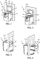
- the invention relates to a disinfecting/sterilizing machine 1 for disinfecting/sterilizing medicals apparatus, comprising:
- Said movable lid 7 may comprise said cover body which is hinged to the casing so as to be displaced from said first closed position PL1 to said second open position PL2, and vice versa.
- Said machine may comprise a locking system, such as an electromagnetic lock, configured to lock said cover body in said first closed position PL1.
- the two parts of the electromagnetic lock are disposed respectively on the frame/casing and the cover body of the lid.
- a pressurized cylinder (not shown) may link said cover body 70 to the frame or casing, so that the restoring force of the pressurized cylinder, greater than the force of gravity on said lid, raises automatically said lid, from the first closed position PL1 to the second open position. Once the locking system unlocks said cover body 70, the lid 7 raises automatically.
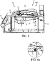
- said movable lid 7 can comprise, apart from said cover body 70, a seal device comprising a seal assembly with a seal plate 71 and a gasket 72 disposed along a periphery of the seal plate 71.
- Said seal device is configured, in said first closed position PL1 of the lid, to seal directly, in an fluid tight manner, said upper tank opening 51, in at least one state of the seal device : the internal surface of said cavity and the underneath surface of said seal plate 71 defines then the sterilizing disinfecting/sterilizing chamber.
- a cleaning cycle is implemented in said disinfecting/sterilizing chamber, by conveying cleaning liquid, or water.
- the machine can comprise one or preferably a plurality of hydraulic circuit.
- the casing comprises a fixed compartment receiving one or a plurality of canisters 10 comprising disinfecting/sterilizing liquids, said machine comprising at least one cleaning circuit comprising a flexible pipe, and a pump, said cleaning circuit being configured to draw the disinfecting liquid from the canister and to convey the liquid into the cavity of the tank in order to clean internal and/or external surfaces of the medical apparatus.
- a first cleaning circuit can provide cleaning liquid to clean the external surface of the medical apparatus.
- the medical apparatus can be immersed in an amount of cleaning liquid received in said tank.
- cleaning liquids can be sprayed onto said medical apparatus.
- a second cleaning circuit can provide liquid to clean the internal surface of the medical apparatus 1.
- the second circuit comprises a plug to connect the internal conduct with this second circuit.
- the bottom of the tank may comprise a discharge coupled with a discharge circuit for emptying the liquids in said tank, such a discharge circuit comprising a flexible pipe.
- Each of the flexible pipe belonging to the cleaning circuit and/or belonging to discharge circuit can be of a overabundant length such that the tank assembly is slideable from first end position P1 to second end position P2, and vice versa, while canister are fixed into a compartment of said casing.
- a guiding system comprising a handling chain is advantageously configured to mechanically handle and guide the flexible pipe when said tank assembly 5 is displaced along the slides from first end position P1 to second end position P2, and vice versa. Flexible pipes are conveniently guided and maintained during this displacement, avoiding a risk of damage of said flexible pipes, for example by pinching.
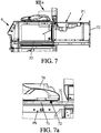
- Said tank assembly 5 can comprise a lateral wall 52 fixedly securely to said tank assembly so as to be movable with the tank assembly 5 and configured to obstruct said first opening 40 wherein said tank assembly 5 is inside the tunnel 4 at second end position P2.
- a gasket may be provided, on the periphery of said first opening, or secured to said wall so that the lateral wall 52 obstructs said first opening 40 in an air tight manner, when said tank assembly is at said second position P2. This provision makes sure no air ingress goes through said casing when the lid 7 is open, preventing cross contamination between the clean room and the dirty room.
- the seal device may comprise an actuator 73 joining said seal plate 71 and the cover body 70, configured, in said first closed position PL1 of said lid, in said second position of the tank assembly 5, to move the seal assembly t between two positions:
- downward position Pa of said seal assembly makes sure said gasket may directly and properly seal in a fluid tight manner the upper tank opening.
- the gasket 72 is provided on an edge of the seal plate 71, said gasket being an inflatable gasket.
- Said seal device comprising a system to inflate said gasket to seal the gasket along the periphery of said cavity of the tank.
- the seal assembly (including the seal plate 71 and gasket 72), is inside the cavity of said tank, thus preventing the sliding of said tank assembly.
- said gasket 72 may be configured to seal in an air tight manner the upper wall 31 with the seal plate 71 in order to obstruct said second opening 41 in an air tight manner, in at least one state of the gasket. This provision makes sure that no air ingress goes through said second opening of said casing when tank assembly 5 is moved from second position P2 inside said tunnel up to first position P1, preventing cross contamination between the dirty room and the clean room.
- the gasket 72 may be provided on an edge of the seal plate 71, comprising a peripheral groove.
- the peripheral groove receives a peripheral rib of said gasket 72.
- Said gasket may be an inflatable gasket, said seal device comprising a system to inflate said gasket to seal the gasket along:
- the inflatable gasket 72 may be inflated when the tank assembly 5 is in a static position, namely at said downward position Pa or at said upward position Pb.
- the inflatable gasket 72 is deflated before moving the seal assembly upward or downward.
- the lid in order to prevent air ingress when tank assembly 5 is moved up to first position P1, can comprise a second seal device, with a (second) gasket configured to seal second opening, in said first closed position of the lid, and irrespective of the position of the seal plate of said (first) seal device.
- the second end of the tunnel 4 disposed opposed to said first opening 40 is closed, said casing comprising a user interface 9 at said second end.
- This user interface may comprise a screen such as a touch screen and or a controller keyboard.
- Said disinfecting/sterilizing machine can comprise a partition wall 8 extending from said casing above the level of the second opening 41, said partition wall being positioned between the first opening 40 and the second opening 41, or positioned at said second opening.
- Said casing 3 and said partition wall 8 are intended to close in an air tight manner a trough opening Op in a wall W separating from each other two separates rooms, for instance a service room (" dirty room ”) and a theater room (“ clean room ”) typically of controlled atmosphere.
- Said partition wall 8 may comprise a window 80 giving visual access between the two room.
- the invention also relates to an installation comprising a wall W separating two separate rooms for instance said service room and theater room, said wall W comprising a through opening Op and a disinfecting/sterilizing apparatus invention, said casing 3 and said partition wall closing in an air tight manner the through opening Op in said wall.
- Said tank assembly 5 projects from a first side of the wall W at said first end position P1 so that a medical apparatus can be inserted or extracted from this first side, for example from the clean room, said tank assembly being positioned at said second end position P2 on a second side of the wall W so that a medical apparatus may be inserted or extracted through said second opening 4 from said second side of the wall, for example from the service room.
- the tank assembly can project at said first end position P1 in a clean atmosphere of the clean room.
- said machine can comprise a motorized fan device, configured to draw air from said clean atmosphere and have the tunnel 4 in overpressure with air from the clean atmosphere. Having the tunnel in a slight overpressure with the air from the clean room makes sure that no air ingress comes from the service room up to theater room when the tank assembly is slid from second end position up to first end position.
- the programmable controller may implement hereafter a step wherein a flushing liquid such as water is used to rinse the internal and external surfaces of the medical apparatus.
- a flushing liquid such as water
- the tank may be displaced automatically from said second position P2, inside the tunnel up to first position P1 wherein the tank assembly 5 projects from first opening, so that the cleaned ondoscope may be extracted from said theater room.
- An actuator 53 (such as a pneumatic cylinder or an electric cylinder, or an electrical motor coupled with a driving belt or a gear rack) can drive the movement of the tank from first end position P1 to second end position P2, and vice versa.
- the programmable controller of the machine implements the chorological steps of a control sequence comprising the steps of :
- the total travel of the tank assembly necessary to pass from said second position of the tank assembly, inside said tunnel, to said first position can be of the order of the length of the tank assembly in the direction of the slides, that is to say around half of the travel necessary for the bath group to pass from first end run to said second end run in the machine according to document WO 2014/083524 A1 .
- this length is at least 200% of the length of the bath in the direction of the slides.
- the travel of tank assembly to pass from first end position up to second end position can be advantageously less than 200% of the length L of the tank in the direction of the slides, for example between 90% and 180%, in particularly between 90% and 150% of the length L of the tank in the direction of the slides,.
- This travel can be between 300mm and 700mm, depending of the dimension of the tank.
Landscapes
- Health & Medical Sciences (AREA)
- Life Sciences & Earth Sciences (AREA)
- General Health & Medical Sciences (AREA)
- Surgery (AREA)
- Veterinary Medicine (AREA)
- Public Health (AREA)
- Animal Behavior & Ethology (AREA)
- Nuclear Medicine, Radiotherapy & Molecular Imaging (AREA)
- Chemical Kinetics & Catalysis (AREA)
- General Chemical & Material Sciences (AREA)
- Physics & Mathematics (AREA)
- Biophysics (AREA)
- Chemical & Material Sciences (AREA)
- Optics & Photonics (AREA)
- Pathology (AREA)
- Radiology & Medical Imaging (AREA)
- Epidemiology (AREA)
- Engineering & Computer Science (AREA)
- Biomedical Technology (AREA)
- Heart & Thoracic Surgery (AREA)
- Medical Informatics (AREA)
- Molecular Biology (AREA)
- Apparatus For Disinfection Or Sterilisation (AREA)
- Endoscopes (AREA)
Priority Applications (5)
| Application Number | Priority Date | Filing Date | Title |
|---|---|---|---|
| ES18306181T ES2993165T3 (en) | 2018-09-07 | 2018-09-07 | Disinfecting/sterilizing machine for medicals apparatus such as endoscopes |
| EP18306181.1A EP3620180B1 (fr) | 2018-09-07 | 2018-09-07 | Machine de désinfection/stérilisation pour des appareils médicaux tels que des endoscopes |
| CN201980057383.7A CN112672768B (zh) | 2018-09-07 | 2019-09-06 | 用于医疗器械如内窥镜的消毒/灭菌机器 |
| AU2019335392A AU2019335392B2 (en) | 2018-09-07 | 2019-09-06 | Disinfecting/sterilizing machine for medicals apparatus such as endoscopes |
| PCT/US2019/049896 WO2020051421A1 (fr) | 2018-09-07 | 2019-09-06 | Machine de désinfection/stérilisation d'appareils médicaux tels que des endoscopes |
Applications Claiming Priority (1)
| Application Number | Priority Date | Filing Date | Title |
|---|---|---|---|
| EP18306181.1A EP3620180B1 (fr) | 2018-09-07 | 2018-09-07 | Machine de désinfection/stérilisation pour des appareils médicaux tels que des endoscopes |
Publications (3)
| Publication Number | Publication Date |
|---|---|
| EP3620180A1 true EP3620180A1 (fr) | 2020-03-11 |
| EP3620180B1 EP3620180B1 (fr) | 2024-08-07 |
| EP3620180C0 EP3620180C0 (fr) | 2024-08-07 |
Family
ID=63637833
Family Applications (1)
| Application Number | Title | Priority Date | Filing Date |
|---|---|---|---|
| EP18306181.1A Active EP3620180B1 (fr) | 2018-09-07 | 2018-09-07 | Machine de désinfection/stérilisation pour des appareils médicaux tels que des endoscopes |
Country Status (5)
| Country | Link |
|---|---|
| EP (1) | EP3620180B1 (fr) |
| CN (1) | CN112672768B (fr) |
| AU (1) | AU2019335392B2 (fr) |
| ES (1) | ES2993165T3 (fr) |
| WO (1) | WO2020051421A1 (fr) |
Cited By (3)
| Publication number | Priority date | Publication date | Assignee | Title |
|---|---|---|---|---|
| US11051687B2 (en) * | 2016-12-09 | 2021-07-06 | Ecolab Usa Inc. | Machine for treating a medical apparatus |
| IT202100000746A1 (it) * | 2021-01-18 | 2022-07-18 | Mdg Eng S R L | Apparecchiatura disinfettatrice/sterilizzatrice per la disinfezione/sterilizzazione automatica di endoscopi |
| WO2024226949A1 (fr) * | 2023-04-28 | 2024-10-31 | Ecolab Usa Inc. | Machine de traitement d'un appareil medical |
Citations (8)
| Publication number | Priority date | Publication date | Assignee | Title |
|---|---|---|---|---|
| JPH05317234A (ja) * | 1991-10-09 | 1993-12-03 | Olympus Optical Co Ltd | 内視鏡診断システム |
| WO2003072146A1 (fr) * | 2002-02-28 | 2003-09-04 | Olympus Corporation | Sterilisateur et chambre de sterilisation |
| US20050012281A1 (en) * | 2003-07-16 | 2005-01-20 | Steris Inc. | Inflatable seal |
| EP1787731A2 (fr) * | 2005-11-16 | 2007-05-23 | International Steel Co. SpA | Appareil de lavage, en particulier pour désinfection thermique |
| WO2008097430A2 (fr) * | 2007-02-05 | 2008-08-14 | American Sterilizer Company | Enceinte à plusieurs compartiments présentant des passages de flux entre eux |
| WO2014008324A1 (fr) | 2012-07-03 | 2014-01-09 | Weinmeier Robert | Sac pour clubs de golf personnalisable et son procédé d'utilisation |
| WO2014083524A1 (fr) | 2012-11-30 | 2014-06-05 | Ase S.P.A. | Machine de désinfection/stérilisation d'endoscopes |
| WO2018104690A1 (fr) * | 2016-12-09 | 2018-06-14 | Ecolab Usa Inc | Machine de traitement d'un appareil medical |
Family Cites Families (6)
| Publication number | Priority date | Publication date | Assignee | Title |
|---|---|---|---|---|
| US6919057B2 (en) * | 2002-04-04 | 2005-07-19 | Steris Inc. | Automated endoscope reprocessor |
| US6884392B2 (en) * | 2002-11-12 | 2005-04-26 | Minntech Corporation | Apparatus and method for steam reprocessing flexible endoscopes |
| JP5127619B2 (ja) * | 2008-07-24 | 2013-01-23 | オリンパスメディカルシステムズ株式会社 | 内視鏡洗浄消毒装置、内視鏡洗浄消毒装置を用いた内視鏡の洗浄方法 |
| ITVI20110260A1 (it) * | 2011-09-29 | 2013-03-30 | I M S S R L | Macchina per il trattamento sanificante di dispositivi medici rigidi e flessibili |
| CN104144633B (zh) * | 2012-09-18 | 2016-05-18 | 奥林巴斯株式会社 | 内窥镜清洗消毒装置 |
| IT201700106764A1 (it) * | 2017-09-25 | 2019-03-25 | Medical Devices Group S R L | Metodo e apparecchiatura per la disinfezione/sterilizzazione automatica di endoscopi |
-
2018
- 2018-09-07 EP EP18306181.1A patent/EP3620180B1/fr active Active
- 2018-09-07 ES ES18306181T patent/ES2993165T3/es active Active
-
2019
- 2019-09-06 AU AU2019335392A patent/AU2019335392B2/en active Active
- 2019-09-06 WO PCT/US2019/049896 patent/WO2020051421A1/fr not_active Ceased
- 2019-09-06 CN CN201980057383.7A patent/CN112672768B/zh active Active
Patent Citations (9)
| Publication number | Priority date | Publication date | Assignee | Title |
|---|---|---|---|---|
| JPH05317234A (ja) * | 1991-10-09 | 1993-12-03 | Olympus Optical Co Ltd | 内視鏡診断システム |
| WO2003072146A1 (fr) * | 2002-02-28 | 2003-09-04 | Olympus Corporation | Sterilisateur et chambre de sterilisation |
| US20050012281A1 (en) * | 2003-07-16 | 2005-01-20 | Steris Inc. | Inflatable seal |
| EP1787731A2 (fr) * | 2005-11-16 | 2007-05-23 | International Steel Co. SpA | Appareil de lavage, en particulier pour désinfection thermique |
| WO2008097430A2 (fr) * | 2007-02-05 | 2008-08-14 | American Sterilizer Company | Enceinte à plusieurs compartiments présentant des passages de flux entre eux |
| WO2014008324A1 (fr) | 2012-07-03 | 2014-01-09 | Weinmeier Robert | Sac pour clubs de golf personnalisable et son procédé d'utilisation |
| WO2014083524A1 (fr) | 2012-11-30 | 2014-06-05 | Ase S.P.A. | Machine de désinfection/stérilisation d'endoscopes |
| EP2925373A1 (fr) * | 2012-11-30 | 2015-10-07 | Ase S.R.L. | Machine de désinfection/stérilisation d'endoscopes |
| WO2018104690A1 (fr) * | 2016-12-09 | 2018-06-14 | Ecolab Usa Inc | Machine de traitement d'un appareil medical |
Cited By (3)
| Publication number | Priority date | Publication date | Assignee | Title |
|---|---|---|---|---|
| US11051687B2 (en) * | 2016-12-09 | 2021-07-06 | Ecolab Usa Inc. | Machine for treating a medical apparatus |
| IT202100000746A1 (it) * | 2021-01-18 | 2022-07-18 | Mdg Eng S R L | Apparecchiatura disinfettatrice/sterilizzatrice per la disinfezione/sterilizzazione automatica di endoscopi |
| WO2024226949A1 (fr) * | 2023-04-28 | 2024-10-31 | Ecolab Usa Inc. | Machine de traitement d'un appareil medical |
Also Published As
| Publication number | Publication date |
|---|---|
| EP3620180B1 (fr) | 2024-08-07 |
| AU2019335392B2 (en) | 2024-12-19 |
| AU2019335392A1 (en) | 2021-04-01 |
| CN112672768B (zh) | 2023-09-19 |
| ES2993165T3 (en) | 2024-12-23 |
| CN112672768A (zh) | 2021-04-16 |
| EP3620180C0 (fr) | 2024-08-07 |
| WO2020051421A1 (fr) | 2020-03-12 |
Similar Documents
| Publication | Publication Date | Title |
|---|---|---|
| AU2019335392B2 (en) | Disinfecting/sterilizing machine for medicals apparatus such as endoscopes | |
| EP1477106A1 (fr) | Recipient de sterilisation a la vapeur haute pression et haute temperature pour endoscope et sterilisateur pour le nettoyage d'endoscope | |
| JP4789590B2 (ja) | 内視鏡洗滌消毒装置、該内視鏡洗滌消毒装置の洗滌消毒制御方法 | |
| US20050012281A1 (en) | Inflatable seal | |
| US20070107152A1 (en) | Apparatus for washing and disinfecting medical instruments | |
| CN107296967A (zh) | 一种全自动医用器具高效消毒灭菌装置 | |
| CN1989893B (zh) | 柜型内窥镜处理器 | |
| JP5767424B1 (ja) | 内視鏡洗浄消毒装置 | |
| BR112020007170A2 (pt) | método e aparelho para esterilização de endoscópios | |
| EP1803470B1 (fr) | Récipient de stockage pour nettoyer/stériliser des endoscopes | |
| CN108894685A (zh) | 医用清洗机的柜门 | |
| CN110639042A (zh) | 一种泌尿外科用多功能消毒设备 | |
| CN115228849B (zh) | 一种全自动内镜多舱清洗机 | |
| CN218797717U (zh) | 一种内窥镜清洗消毒设备 | |
| CN115780376A (zh) | 一种内窥镜清洗消毒设备 | |
| KR100734972B1 (ko) | 기구 소독 장치 | |
| CN215022749U (zh) | 一种内分泌用检查工具消毒装置 | |
| JP2516177B2 (ja) | 医療用具用洗浄消毒装置の扉開閉機構 | |
| JP6177167B2 (ja) | 内視鏡洗浄消毒装置 | |
| US20090032137A1 (en) | Apparatus And Method | |
| CN119499415A (zh) | 一种过氧化氢等离子体灭菌设备 | |
| JP2001141057A (ja) | 気密容器の気密機構 | |
| CN114918177A (zh) | 一种内分泌医用器械智能清洗消毒装置 | |
| JPH0824705B2 (ja) | 医療用具用洗浄消毒装置の扉開閉機構 | |
| JP2018000269A (ja) | 内視鏡リプロセッサ |
Legal Events
| Date | Code | Title | Description |
|---|---|---|---|
| PUAI | Public reference made under article 153(3) epc to a published international application that has entered the european phase |
Free format text: ORIGINAL CODE: 0009012 |
|
| STAA | Information on the status of an ep patent application or granted ep patent |
Free format text: STATUS: THE APPLICATION HAS BEEN PUBLISHED |
|
| AK | Designated contracting states |
Kind code of ref document: A1 Designated state(s): AL AT BE BG CH CY CZ DE DK EE ES FI FR GB GR HR HU IE IS IT LI LT LU LV MC MK MT NL NO PL PT RO RS SE SI SK SM TR |
|
| AX | Request for extension of the european patent |
Extension state: BA ME |
|
| STAA | Information on the status of an ep patent application or granted ep patent |
Free format text: STATUS: REQUEST FOR EXAMINATION WAS MADE |
|
| 17P | Request for examination filed |
Effective date: 20200911 |
|
| RBV | Designated contracting states (corrected) |
Designated state(s): AL AT BE BG CH CY CZ DE DK EE ES FI FR GB GR HR HU IE IS IT LI LT LU LV MC MK MT NL NO PL PT RO RS SE SI SK SM TR |
|
| STAA | Information on the status of an ep patent application or granted ep patent |
Free format text: STATUS: EXAMINATION IS IN PROGRESS |
|
| 17Q | First examination report despatched |
Effective date: 20230502 |
|
| REG | Reference to a national code |
Ref country code: DE Ref legal event code: R079 Free format text: PREVIOUS MAIN CLASS: A61L0002180000 Ipc: A61B0090700000 Ref country code: DE Ref legal event code: R079 Ref document number: 602018072700 Country of ref document: DE Free format text: PREVIOUS MAIN CLASS: A61L0002180000 Ipc: A61B0090700000 |
|
| GRAP | Despatch of communication of intention to grant a patent |
Free format text: ORIGINAL CODE: EPIDOSNIGR1 |
|
| STAA | Information on the status of an ep patent application or granted ep patent |
Free format text: STATUS: GRANT OF PATENT IS INTENDED |
|
| RIC1 | Information provided on ipc code assigned before grant |
Ipc: A61B 1/12 20060101ALI20240131BHEP Ipc: A61L 2/18 20060101ALI20240131BHEP Ipc: A61B 90/70 20160101AFI20240131BHEP |
|
| INTG | Intention to grant announced |
Effective date: 20240301 |
|
| GRAS | Grant fee paid |
Free format text: ORIGINAL CODE: EPIDOSNIGR3 |
|
| GRAA | (expected) grant |
Free format text: ORIGINAL CODE: 0009210 |
|
| STAA | Information on the status of an ep patent application or granted ep patent |
Free format text: STATUS: THE PATENT HAS BEEN GRANTED |
|
| AK | Designated contracting states |
Kind code of ref document: B1 Designated state(s): AL AT BE BG CH CY CZ DE DK EE ES FI FR GB GR HR HU IE IS IT LI LT LU LV MC MK MT NL NO PL PT RO RS SE SI SK SM TR |
|
| REG | Reference to a national code |
Ref country code: GB Ref legal event code: FG4D |
|
| REG | Reference to a national code |
Ref country code: CH Ref legal event code: EP |
|
| REG | Reference to a national code |
Ref country code: DE Ref legal event code: R096 Ref document number: 602018072700 Country of ref document: DE |
|
| REG | Reference to a national code |
Ref country code: IE Ref legal event code: FG4D |
|
| U01 | Request for unitary effect filed |
Effective date: 20240826 |
|
| U07 | Unitary effect registered |
Designated state(s): AT BE BG DE DK EE FI FR IT LT LU LV MT NL PT RO SE SI Effective date: 20240904 |
|
| U20 | Renewal fee for the european patent with unitary effect paid |
Year of fee payment: 7 Effective date: 20240906 |
|
| REG | Reference to a national code |
Ref country code: ES Ref legal event code: FG2A Ref document number: 2993165 Country of ref document: ES Kind code of ref document: T3 Effective date: 20241223 |
|
| PG25 | Lapsed in a contracting state [announced via postgrant information from national office to epo] |
Ref country code: GR Free format text: LAPSE BECAUSE OF FAILURE TO SUBMIT A TRANSLATION OF THE DESCRIPTION OR TO PAY THE FEE WITHIN THE PRESCRIBED TIME-LIMIT Effective date: 20241108 Ref country code: PL Free format text: LAPSE BECAUSE OF FAILURE TO SUBMIT A TRANSLATION OF THE DESCRIPTION OR TO PAY THE FEE WITHIN THE PRESCRIBED TIME-LIMIT Effective date: 20240807 |
|
| PG25 | Lapsed in a contracting state [announced via postgrant information from national office to epo] |
Ref country code: IS Free format text: LAPSE BECAUSE OF FAILURE TO SUBMIT A TRANSLATION OF THE DESCRIPTION OR TO PAY THE FEE WITHIN THE PRESCRIBED TIME-LIMIT Effective date: 20241207 |
|
| PG25 | Lapsed in a contracting state [announced via postgrant information from national office to epo] |
Ref country code: HR Free format text: LAPSE BECAUSE OF FAILURE TO SUBMIT A TRANSLATION OF THE DESCRIPTION OR TO PAY THE FEE WITHIN THE PRESCRIBED TIME-LIMIT Effective date: 20240807 |
|
| PG25 | Lapsed in a contracting state [announced via postgrant information from national office to epo] |
Ref country code: RS Free format text: LAPSE BECAUSE OF FAILURE TO SUBMIT A TRANSLATION OF THE DESCRIPTION OR TO PAY THE FEE WITHIN THE PRESCRIBED TIME-LIMIT Effective date: 20241107 |
|
| PG25 | Lapsed in a contracting state [announced via postgrant information from national office to epo] |
Ref country code: RS Free format text: LAPSE BECAUSE OF FAILURE TO SUBMIT A TRANSLATION OF THE DESCRIPTION OR TO PAY THE FEE WITHIN THE PRESCRIBED TIME-LIMIT Effective date: 20241107 Ref country code: PL Free format text: LAPSE BECAUSE OF FAILURE TO SUBMIT A TRANSLATION OF THE DESCRIPTION OR TO PAY THE FEE WITHIN THE PRESCRIBED TIME-LIMIT Effective date: 20240807 Ref country code: IS Free format text: LAPSE BECAUSE OF FAILURE TO SUBMIT A TRANSLATION OF THE DESCRIPTION OR TO PAY THE FEE WITHIN THE PRESCRIBED TIME-LIMIT Effective date: 20241207 Ref country code: HR Free format text: LAPSE BECAUSE OF FAILURE TO SUBMIT A TRANSLATION OF THE DESCRIPTION OR TO PAY THE FEE WITHIN THE PRESCRIBED TIME-LIMIT Effective date: 20240807 Ref country code: GR Free format text: LAPSE BECAUSE OF FAILURE TO SUBMIT A TRANSLATION OF THE DESCRIPTION OR TO PAY THE FEE WITHIN THE PRESCRIBED TIME-LIMIT Effective date: 20241108 |
|
| PG25 | Lapsed in a contracting state [announced via postgrant information from national office to epo] |
Ref country code: SM Free format text: LAPSE BECAUSE OF FAILURE TO SUBMIT A TRANSLATION OF THE DESCRIPTION OR TO PAY THE FEE WITHIN THE PRESCRIBED TIME-LIMIT Effective date: 20240807 |
|
| PG25 | Lapsed in a contracting state [announced via postgrant information from national office to epo] |
Ref country code: CZ Free format text: LAPSE BECAUSE OF FAILURE TO SUBMIT A TRANSLATION OF THE DESCRIPTION OR TO PAY THE FEE WITHIN THE PRESCRIBED TIME-LIMIT Effective date: 20240807 |
|
| PG25 | Lapsed in a contracting state [announced via postgrant information from national office to epo] |
Ref country code: SK Free format text: LAPSE BECAUSE OF FAILURE TO SUBMIT A TRANSLATION OF THE DESCRIPTION OR TO PAY THE FEE WITHIN THE PRESCRIBED TIME-LIMIT Effective date: 20240807 |
|
| PLBE | No opposition filed within time limit |
Free format text: ORIGINAL CODE: 0009261 |
|
| STAA | Information on the status of an ep patent application or granted ep patent |
Free format text: STATUS: NO OPPOSITION FILED WITHIN TIME LIMIT |
|
| PG25 | Lapsed in a contracting state [announced via postgrant information from national office to epo] |
Ref country code: MC Free format text: LAPSE BECAUSE OF FAILURE TO SUBMIT A TRANSLATION OF THE DESCRIPTION OR TO PAY THE FEE WITHIN THE PRESCRIBED TIME-LIMIT Effective date: 20240807 |
|
| 26N | No opposition filed |
Effective date: 20250508 |
|
| U20 | Renewal fee for the european patent with unitary effect paid |
Year of fee payment: 8 Effective date: 20250807 |
|
| REG | Reference to a national code |
Ref country code: CH Ref legal event code: U11 Free format text: ST27 STATUS EVENT CODE: U-0-0-U10-U11 (AS PROVIDED BY THE NATIONAL OFFICE) Effective date: 20251001 |
|
| PGFP | Annual fee paid to national office [announced via postgrant information from national office to epo] |
Ref country code: NO Payment date: 20250909 Year of fee payment: 8 |
|
| PGFP | Annual fee paid to national office [announced via postgrant information from national office to epo] |
Ref country code: GB Payment date: 20250703 Year of fee payment: 8 |
|
| PGFP | Annual fee paid to national office [announced via postgrant information from national office to epo] |
Ref country code: IE Payment date: 20250702 Year of fee payment: 8 |
|
| PGFP | Annual fee paid to national office [announced via postgrant information from national office to epo] |
Ref country code: CH Payment date: 20251001 Year of fee payment: 8 |
|
| PG25 | Lapsed in a contracting state [announced via postgrant information from national office to epo] |
Ref country code: CY Free format text: LAPSE BECAUSE OF FAILURE TO SUBMIT A TRANSLATION OF THE DESCRIPTION OR TO PAY THE FEE WITHIN THE PRESCRIBED TIME-LIMIT; INVALID AB INITIO Effective date: 20180907 |
|
| PGFP | Annual fee paid to national office [announced via postgrant information from national office to epo] |
Ref country code: ES Payment date: 20251017 Year of fee payment: 8 |
|
| PG25 | Lapsed in a contracting state [announced via postgrant information from national office to epo] |
Ref country code: HU Free format text: LAPSE BECAUSE OF FAILURE TO SUBMIT A TRANSLATION OF THE DESCRIPTION OR TO PAY THE FEE WITHIN THE PRESCRIBED TIME-LIMIT; INVALID AB INITIO Effective date: 20180907 |