EP3620190A1 - Hämodialyse-geräteanordnung - Google Patents
Hämodialyse-geräteanordnung Download PDFInfo
- Publication number
- EP3620190A1 EP3620190A1 EP18192552.0A EP18192552A EP3620190A1 EP 3620190 A1 EP3620190 A1 EP 3620190A1 EP 18192552 A EP18192552 A EP 18192552A EP 3620190 A1 EP3620190 A1 EP 3620190A1
- Authority
- EP
- European Patent Office
- Prior art keywords
- double
- port
- socket
- coupling
- line
- Prior art date
- Legal status (The legal status is an assumption and is not a legal conclusion. Google has not performed a legal analysis and makes no representation as to the accuracy of the status listed.)
- Granted
Links
Images



Classifications
-
- A—HUMAN NECESSITIES
- A61—MEDICAL OR VETERINARY SCIENCE; HYGIENE
- A61M—DEVICES FOR INTRODUCING MEDIA INTO, OR ONTO, THE BODY; DEVICES FOR TRANSDUCING BODY MEDIA OR FOR TAKING MEDIA FROM THE BODY; DEVICES FOR PRODUCING OR ENDING SLEEP OR STUPOR
- A61M1/00—Suction or pumping devices for medical purposes; Devices for carrying-off, for treatment of, or for carrying-over, body-liquids; Drainage systems
- A61M1/14—Dialysis systems; Artificial kidneys; Blood oxygenators ; Reciprocating systems for treatment of body fluids, e.g. single needle systems for hemofiltration or pheresis
-
- A—HUMAN NECESSITIES
- A61—MEDICAL OR VETERINARY SCIENCE; HYGIENE
- A61M—DEVICES FOR INTRODUCING MEDIA INTO, OR ONTO, THE BODY; DEVICES FOR TRANSDUCING BODY MEDIA OR FOR TAKING MEDIA FROM THE BODY; DEVICES FOR PRODUCING OR ENDING SLEEP OR STUPOR
- A61M1/00—Suction or pumping devices for medical purposes; Devices for carrying-off, for treatment of, or for carrying-over, body-liquids; Drainage systems
- A61M1/36—Other treatment of blood in a by-pass of the natural circulatory system, e.g. temperature adaptation, irradiation ; Extra-corporeal blood circuits
- A61M1/3621—Extra-corporeal blood circuits
- A61M1/3643—Priming, rinsing before or after use
-
- A—HUMAN NECESSITIES
- A61—MEDICAL OR VETERINARY SCIENCE; HYGIENE
- A61M—DEVICES FOR INTRODUCING MEDIA INTO, OR ONTO, THE BODY; DEVICES FOR TRANSDUCING BODY MEDIA OR FOR TAKING MEDIA FROM THE BODY; DEVICES FOR PRODUCING OR ENDING SLEEP OR STUPOR
- A61M1/00—Suction or pumping devices for medical purposes; Devices for carrying-off, for treatment of, or for carrying-over, body-liquids; Drainage systems
- A61M1/36—Other treatment of blood in a by-pass of the natural circulatory system, e.g. temperature adaptation, irradiation ; Extra-corporeal blood circuits
- A61M1/3621—Extra-corporeal blood circuits
- A61M1/367—Circuit parts not covered by the preceding subgroups of group A61M1/3621
-
- A—HUMAN NECESSITIES
- A61—MEDICAL OR VETERINARY SCIENCE; HYGIENE
- A61M—DEVICES FOR INTRODUCING MEDIA INTO, OR ONTO, THE BODY; DEVICES FOR TRANSDUCING BODY MEDIA OR FOR TAKING MEDIA FROM THE BODY; DEVICES FOR PRODUCING OR ENDING SLEEP OR STUPOR
- A61M1/00—Suction or pumping devices for medical purposes; Devices for carrying-off, for treatment of, or for carrying-over, body-liquids; Drainage systems
- A61M1/36—Other treatment of blood in a by-pass of the natural circulatory system, e.g. temperature adaptation, irradiation ; Extra-corporeal blood circuits
- A61M1/3621—Extra-corporeal blood circuits
- A61M1/3643—Priming, rinsing before or after use
- A61M1/3644—Mode of operation
- A61M1/3646—Expelling the residual body fluid after use, e.g. back to the body
Definitions
- the invention relates to a hemodialysis device arrangement with a base device, which has a device housing and an internal fluid inside the device housing, and with an external fluid set forming an external fluid, outside the device housing, which is fluidly connected to the base device or the internal fluid via couplable fluid couplings is.
- Hemodialysis device arrangements are generally divided into two fluids: an external fluid and an internal fluid.
- the internal fluid is designed for multiple and permanent use and therefore consists of stable materials that can be disinfected. As a rule, the internal fluid does not have any blood-carrying lines.
- External fluidics on the other hand, has, among other things, all blood-carrying lines and components of the so-called extracorporeal blood circuit. External fluidics are designed for single use only to avoid blood-borne infections.
- the external fluid is usually arranged on an operator interface that is freely accessible or accessible without tools.
- the interface often has mechanical peristaltic pump facial expressions into which a tube of external fluid can be inserted in order to form a pump, for example the blood pump in the extracorporeal blood circuit of external fluid.
- the fluidic connection between the internal fluid and the external fluid is usually established via fluidic couplings, which are isolated.
- the entire workflow of a patient's dialysis treatment begins with the application of the external fluid designed as a line set to the base device or the interface in order to disinfect the external fluid and in particular the extracorporeal blood circuit and to fill it with a pre-filling liquid.
- the external fluid then has to be changed to fluidly connect the venous and arterial line ends to the arterial and venous patient access in order to start the blood purification.
- the external fluid is changed again in order to completely pump the blood out of the extracorporeal blood circuit of the external fluid back to the patient.
- the object of the invention is to simplify the handling of the external fluid of a hemodialysis device arrangement during the entire treatment cycle.
- the hemodialysis device arrangement consists of a basic device which has a device housing and a stationary internal fluid inside the device housing, and an external fluid set which forms a non-stationary external fluid outside the device housing.
- the external fluid is preferably made entirely of plastic parts and is fluidly connected to the internal fluid of the base unit via couplable fluid couplings.
- the term “stationary” always refers to the basic device, which in turn can of course be designed to be movable.
- the fluid couplings are preferably arranged on an interface of the basic device, for example on a freely accessible device front.
- the external fluid has the lines forming the extracorporeal blood circuit and can be designed as a single-use article, but can also be designed to be used and disinfected several times.
- a fluid is to be understood as a liquid, a gas or a mixture thereof.
- a fluidic coaxial double-port coupling which is formed by a base device-side stationary double-port socket and a corresponding external set-side double-port plug which is detachably plugged onto the double-port socket.
- the double-port plug and the double-port socket each have a fluidic central line and a coaxial fluidic ring line surrounding the central line.
- the two central lines and the two ring lines are each fluidly connected to one another.
- “ring-shaped” is not necessarily to be understood as a circular ring, but can also be understood as an oval, a rectangle, etc.
- socket and “plug” have no particular meaning in the present case with regard to which part is inserted into which part, but the two differing terms are only used for easier description and differentiation.
- plug is used to express that this is the non-stationary, ie mobile part of the coupling that is actively plugged into the stationary socket or that it is detached and removed from it.
- a clutch is to be understood as meaning a clutch facial expression which is simple mechanical and fluid mechanical Ensures connection or can be released again, for example in the form of a bayonet coupling or a coupling nut coupling.
- a locking means is provided on the device side, wherein the locking means in its locking position blocks the double-port plug in its coupling position on the stationary double-port socket.
- the locking means makes it easy for the user to see that the double-port coupling is coupled and locked.
- the device-side locking means enables the correct locking of the double-port coupling to be checked.
- the locking means can be designed, for example, as a swivel bracket which can be swiveled over the coupled double-port plug in order to axially and / or rotationally lock the double-port plug in its locking position. In this way, since the locking means is an integral part of the basic device and not a single-use item, the manufacturing costs for the single-item external fluid can be kept low.
- the double port connector and the corresponding coupling can be designed with Luer facial expressions.
- the locking means particularly preferably has a flow reversing cap which, when the double-port plug is not coupled, has the double-port socket in a rinsing position of the locking means closes that the socket central line is fluidly connected to the socket ring line.
- the flow reversal cap can also be formed separately from the locking means. With the flow reversing cap provided on the device side, it is possible to rinse or disinfect the socket central line and the socket ring line as well as the mechanical socket coupling at the same time. Furthermore, when the double port coupling is not in use, it is mechanically protected from contamination by the flow reversing cap.
- the locking means and / or the flow reversing cap is preferably assigned a position detector which detects the locking position and / or the rinsing position of the locking means. In this way, a high level of functional and process reliability is achieved.
- the base device is fluidly assigned a substituate liquid source, which is fluidly connected to the socket ring line or the socket central line.
- the substituate pump can basically be designed as an external pump.
- the base unit particularly preferably has an internal substituate pump which pumps the substituate liquid from the substituate liquid source to the double-port coupling.
- Substitute fluid can thus be fed from the source of the substituate fluid into the extracorporeal blood circuit of the external fluid set via the base unit-side double port socket.
- the substituate fluid can also be used to prime the extracorporeal bloodstream of external fluids.
- the substitute fluid can also be used after the actual blood treatment to push the blood column out of the extracorporeal blood circuit of the external fluid back to the patient.
- a waste liquid target is preferably assigned to the base device, which is fluid with the socket central line or the socket ring line connected is.
- the coaxial double-port coupling can be used, for example, to establish the fluidic connections between the external fluid and the internal fluid, which are required for priming the extracorporeal circuit of the external fluid or for rinsing or disinfecting the extracorporeal blood circuit of the external fluid.
- the waste liquid target can be understood to mean, for example, the public sewage network or an internal sewage tank.
- the non-stationary external set preferably has a double port adapter with the double port connector and a separate blood circuit line arrangement which forms the extracorporeal blood circuit during the hemodialysis treatment.
- the blood circuit line arrangement has at its arterial and at its venous line end an arterial coupling socket and a venous coupling socket which can be coupled to corresponding coupling plugs on the patient.
- the double port adapter has a corresponding arterial coupling plug that is fluidly connected to the substituate fluid source and has a corresponding venous coupling plug that is fluidly connected to the waste liquid container.
- the two coupling sockets of the blood circuit line arrangement can be fluidly coupled to the double port adapter for filling the blood circuit line arrangement, so that the blood circuit line arrangement can be pre-filled with a suitable pre-filling liquid, for example with the substituate liquid.
- the suitable pre-filling liquid flows into the arterial line end of the blood circuit line arrangement and finally flows through the venous line end to the device-side waste liquid container.
- the blood circuit line arrangement preferably has a separate substituate access between the two blood circuit line ends, which is formed by an arterial coupling socket.
- the arterial coupling socket of the substituate access is therefore identical in construction to the arterial coupling socket on the arterial line end.
- the source of the substituate can easily be coupled, that is to say fluidly, after the prefilling and during the dialysis treatment with the separate access to the substituent of the blood circuit line arrangement. Due to the different design of the arterial coupling bush and the venous coupling bush, faulty coupling can be practically ruled out, as a result of which the operational safety is considerably increased.
- a check valve is preferably arranged in the blood circuit line arrangement upstream of the venous line end and preferably downstream of the dialyzer and opens in the flow direction to the venous line end and closes in the opposite flow direction. This prevents a malfunction if the blood circuit line arrangement is incorrectly applied.
- a hemodialysis device arrangement 10 is shown, with which blood cleaning can be carried out on a patient.
- the hemodialysis device arrangement 10 is structurally divided into a stationary base device 12 which has a closed device housing 20 in which an internal fluid is arranged. Outside the device housing 20, the hemodialysis device arrangement 10 has an external fluid, which is formed by an external fluid set 14, which essentially consists of a double-port adapter 16 and a blood circuit line arrangement 18.
- the external fluid set 14 is not reusable, but is designed as a disposable item that is used only for a single dialysis treatment and is then disposed of.
- the device housing 20 is fundamentally closed and cannot be opened without tools, so that there is no direct access to the internal fluid for the user and the patient.
- the device housing 20 has on its front side facing the operator a device housing interface 22 which represents the interface between the external fluid and the internal fluid and which has a plurality of fluid couplings for the fluidic connection of the internal fluid to the external fluid.
- the internal fluid and the external fluid are fluidly connected to one another, among other things, via a coaxial double-port coupling 15, by means of which two individual fluidic connections between the internal fluid and the external fluid are established as required.
- the base device 12 has a substituate liquid source 24, which in the present case is designed as an internal substituate liquid tank 25 ′, which contains a substituate liquid 25.
- a substituate pump 31 is arranged downstream of the substituate liquid source 24, through which the substituate liquid 25 can be pumped to a pump target.
- the base device 12 has a prefilling liquid source 26 within the device housing 20, which source is formed by a tank 27 ′ filled with a prefilling liquid 27.
- a pre-fill liquid pump 32 is arranged downstream of the pre-fill liquid source 26 and can pump the pre-fill liquid 27 to a pre-fill liquid target.
- the lines downstream of the two aforementioned pumps 31, 32 are brought together in a three-way source selection valve 36, the outgoing third branch of which leads to the coaxial double-port coupling 15. Furthermore, the base device 12 has a waste liquid container 28 ′ as a waste liquid target 28 for waste liquid 29.
- the external fluid set 14 outside the device housing 20 has a line 62 which forms the extracorporeal blood circuit and which carries blood during blood purification and which is formed by three line sections 62 ', 62 ", 62"' between its arterial line end 68 and its venous line end 69.
- the blood-carrying line 62 is made of plastic, is transparent and plastically deformable.
- a first substituate access 63 which is formed by an arterial coupling bush 121, is provided downstream of the blood pump mechanism 50. Downstream of the first substituate access 63, the blood-carrying line 62 opens into a dialyzer 60, which has a large-area membrane, through which urinary substances can diffuse from the blood to the other side of the membrane into a dialysis liquid, which supplies the dialyzer 60 from a dialysis liquid supply 13 is provided within the device housing 20.
- An alternative or an additional second substituent access 64 which is formed by an arterial coupling socket 122, can be provided downstream of the dialyzer 60 in a second line section 62 ". Downstream of the second substituate access 64, the second line section 62" opens into an air trap 67, which has a third Has substituate access 65, which is formed by an arterial coupling sleeve 123.
- a check valve 66 is arranged downstream of the air trap 67 in the course of the third line section 62 ′′, so that a liquid in the blood-carrying line 62 can only ever flow in one direction from the arterial line end 68 to the venous line end 69.
- the check valve 66 opens downstream third line section 62 "" into a venous coupling plug 130, which forms the venous line end 69.
- FIG. 1-3 A patient 100 is also shown, on whose arm an arterial patient access 102 with an arterial coupling plug 111 and a venous patient access 104 with a venous coupling plug 131 are applied.
- the coaxial double port coupling 15 consists of an internal fluid part and an external fluid part.
- the internal fluid part of the coaxial double-port coupling 15 defines a base-port-side double-port socket 70, which is a fluidic central line 76 and one is the central line 76 ring-shaped surrounding coaxial ring line 74.
- the external fluid part of the coaxial double-port coupling 15 is formed by a double-port adapter 16, which is defined by a plastic adapter body 16 ', which in turn forms a fluidic central line 86 and a coaxial ring line 84 surrounding the central line 86 in a ring.
- the two ring lines 74, 84 and the two central lines 76, 86 are each fluidly connected to one another, so that two mutually independent fluidic connections are established between the internal fluid and the external fluid.
- the plug central line 86 opens into a flexible plug connecting line 81, which has an arterial coupling plug 110 at its end of the line, which can basically be coupled together with all arterial coupling sockets 120-123 due to its mechanical coding.
- the plug ring line 84 fluidly opens into a venous coupling plug 130 which can be coupled together with the venous coupling socket 140.
- a pivoting lever-like locking means 40 is arranged on the device side on the interface 22.
- the locking means 40 has a pivotable and axially displaceable locking means shaft 46, which has markings readable on the outside by a stationary position sensor 44, so that the position sensor 44 can reliably detect three different positions of the locking means 40.
- a biasing spring 47 is coaxially assigned to the locking means shaft 46, for example, so that the shaft 46 is axially preloaded in the proximal direction.
- the three possible positions of the locking means 40 are the non-functional position, the locking position and the flushing position, which will be explained in the following.
- a lever-like structure adjoins the locking means shaft 46, which forms a cover-like flow reversing cap 42 and a locking part 41.
- the double-port coupling plug 80 In the locking position of the locking means 40, the double-port coupling plug 80 is blocked in its locking position by the locking part 41, so that the double-port coupling plug 80 cannot be inadvertently removed from the double-port coupling socket 70.
- a sealing ring 77 is arranged on the inside of the outer cylindrical sleeve wall 78 of the coupling sleeve in a circular sealing ring groove 79, which ensures the reliable fluid-tight seal with the corresponding cylindrical connector wall 88.
- the plug central line 86 is also inserted into the socket central line 76 in a fluid-tight manner, the two ends of the central line having a slightly conical bevel and abutting one another in a fluid-tight manner.
- the double-port coupling socket 70 and the double-port coupling plug 80 have a bayonet lock 72 which corresponds to one another and is formed by a bayonet bar 72 "on the plug side, which projects radially outwards, and a bayonet ring 72 'on the socket side.
- the bayonet bar 72" engages behind the bayonet ring 72 ', as in Fig. 5 shown.
- the hemodialysis device arrangement 10 is shown during priming: the arterial coupling plug 110 and the venous coupling plug 130 of the double-port adapter 16 are coupled and fluidly connected to the corresponding arterial coupling socket 120 of the arterial line end 68 and to the corresponding venous coupling socket 140 of the venous line end 69 .
- the pre-fill liquid 27 is pumped from the direction into the blood line 62 by the activated pre-fill liquid pump 32 and the likewise activated blood pump 50, so that the blood line 62 finally is completely filled with pre-fill liquid. Excess pre-fill liquid eventually flows into the waste liquid container 28.
- the blood line 62 can be filled on both sides.
- the synchronous filling valve 37 is switched over such that the prefilling liquid is pumped into the blood line 62 both from the arterial line end 68 and from the venous line end 69.
- the blood pump 50 pumps about half the flow rate like the pre-fill liquid pump 32, the air escaping from the blood line 62, for example via the substituate access 65 of the air trap 67.
- the two pumps 32, 50 are stopped and the two line ends 68, 69 are applied to the patient 100, as in FIG Figure 2 shown. Furthermore, the arterial coupling plug 110 of the coaxial double coupling 15 is applied to a substituate access 63, so that if necessary with the substituate pump 31 activated, substituate liquid 25 from the substituate liquid source 24 can be introduced into the blood line 62 via the substituate access 63.
- the arterial coupling socket 120 of the arterial line end 68 of the blood circuit line arrangement 18 is again connected to the arterial coupling plug 110 of the coaxial double coupling 15.
- the substituate fluid pump 31 is activated so that the substituate fluid 25 is pumped from the arterial line end 68 into the blood line 62, whereby the blood from the blood line 62 is pumped back into the patient 100 via the venous line end 69.
- the double-port adapter 16 is removed and disposed of.
- the locking means 40 is then pivoted such that the flow reversing cap 42 completely closes the opening of the double-port coupling bush 70.
- the double-port coupling bushing 70 can then be rinsed and / or disinfected by using a rinsing liquid, for example the prefilling liquid 27, is pumped to the double-port coupling bushing 70, which flows from there to the waste liquid container 28.
Landscapes
- Health & Medical Sciences (AREA)
- Heart & Thoracic Surgery (AREA)
- Vascular Medicine (AREA)
- Hematology (AREA)
- Engineering & Computer Science (AREA)
- Anesthesiology (AREA)
- Biomedical Technology (AREA)
- Life Sciences & Earth Sciences (AREA)
- Animal Behavior & Ethology (AREA)
- General Health & Medical Sciences (AREA)
- Public Health (AREA)
- Veterinary Medicine (AREA)
- Cardiology (AREA)
- Urology & Nephrology (AREA)
- Emergency Medicine (AREA)
- External Artificial Organs (AREA)
Abstract
Description
- Die Erfindung bezieht sich auf eine Hämodialyse-Geräteanordnung mit einem Basisgerät, das ein Gerätegehäuse und eine Internfluidik innerhalb des Gerätegehäuses aufweist, und mit einem eine Externfluidik bildenden Externfluidik-Set außerhalb des Gerätegehäuses, das über kuppelbare Fluidkupplungen fluidisch mit dem Basisgerät bzw. der Internfluidik verbunden ist.
- Hämodialyse-Geräteanordnungen nach dem Stand der Technik sind in der Regel fluidisch zweigeteilt in eine Externfluidik und eine Internfluidik. Die Internfluidik ist für den vielfachen und dauerhaften Gebrauch ausgelegt und besteht daher aus standfesten Materialien, die desinfizierbar sind. Die Internfluidik weist in aller Regel keine blutführenden Leitungen auf. Die Externfluidik dagegen weist unter anderem alle blutführenden Leitungen und Komponenten des sogenannten extrakorporalen Blutkreislaufs auf. Die Externfluidik ist schon zur Vermeidung von blutgestützten Infektionen ausschließlich für den Einmalgebrauch ausgelegt.
- Die Internfluidik ist zum größten Teil oder vollständig innerhalb des Gerätegehäuses angeordnet, das in der Regel werkzeuglos nicht geöffnet werden kann. Die Externfluidik dagegen ist in der Regel auf einem Bediener-Interface angeordnet, das frei zugänglich oder werkzeuglos zugänglich ist. Das Interface weist beispielsweise häufig eine mechanische Schlauchpumpen-Mimik auf, in die ein Schlauch der Externfluidik eingelegt werden kann, um auf diese Weise eine Pumpe zu bilden, beispielsweise die Blutpumpe im extrakorporalen Blutkreis der Externfluidik.
- Die fluidische Verbindung zwischen der Internfluidik und der Externfluidik wird in der Regel über fluidische Kupplungen hergestellt, die vereinzelt ausgebildet sind.
- Der komplette Arbeitsablauf einer Dialysebehandlung eines Patienten beginnt mit dem Applizieren der als Leitungsset ausgebildeten Externfluidik an dem Basisgerät bzw. dem Interface, um die Externfluidik und insbesondere den extrakorporalen Blutkreis zu desinfizieren und vorzufüllen mit einer Vorfüllflüssigkeit. Danach muss die Externfluidik umgesteckt werden, um das venöse und das arterielle Leitungsende mit dem arteriellen und dem venösen Patientenzugang fluidisch zu verbinden, um die Blutreinigung starten zu können. Nach dem Abschluss der Blutreinigung wird die Externfluidik erneut umgesteckt, um das Blut aus dem extrakorporalen Blutkreis der Externfluidik vollständig zurück zum Patienten zu pumpen.
- Während des kompletten Behandlungszyklus' findet also ein mehrfaches Umstecken der Leitungen der Externfluidik statt, was u.a. über entsprechende Fluidkupplungen an dem Interface erfolgt. Grundsätzlich besteht hierbei die Gefahr von falschen Verkupplungen. Ferner ist das Umstecken von vielen Einzel-Fluidkupplungen relativ zeitaufwendig.
- Aufgabe der Erfindung ist es demgegenüber, die Handhabung der Externfluidik einer Hämodialyse-Geräteanordnung während des gesamten Behandlungszyklus' zu vereinfachen.
- Diese Aufgabe wird erfindungsgemäß gelöst mit einer Hämodialyse-Geräteanordnung mit den Merkmalen des Anspruchs 1 bzw. mit einem Doppelport-Adapter nach Anspruch 11.
- Die Hämodialyse-Geräteanordnung besteht aus einem Basisgerät, das ein Gerätegehäuse und eine stationäre Internfluidik innerhalb des Gerätegehäuses aufweist, und einem eine nicht-stationäre Externfluidik bildenden Externfluidik-Set außerhalb des Gerätegehäuses. Die Externfluidik ist vorzugsweise vollständig aus Kunststoff-Teilen bestehend und ist über kuppelbare Fluidkupplungen fluidisch mit der Internfluidik des Basisgeräts verbunden. Der Begriff "stationär" bezieht sich vorliegend stets auf das Basisgerät, das seinerseits selbstverständlich beweglich ausgebildet sein kann. Die Fluidkupplungen sind bevorzugt an einem Interface des Basisgeräts angeordnet, beispielsweise an einer frei zugänglichen Gerätefront. Die Externfluidik weist die den extrakorporalen Blutkreislauf bildenden Leitungen auf und kann als Einmal-Artikel ausgebildet sein, kann aber auch mehrmals verwendbar und desinfizierbar ausgebildet sein. Unter einem Fluid ist vorliegend eine Flüssigkeit, ein Gas oder ein Gemisch hieraus zu verstehen.
- Gemäß der Erfindung ist eine fluidische Koaxial-Doppelport-Kupplung vorgesehen, die von einer Basisgerät-seitigen stationären Doppelport-Buchse und einem korrespondierenden Externset-seitigen Doppelport-Stecker gebildet ist, der auf die Doppelport-Buchse lösbar aufgesteckt ist. Der Doppelport-Stecker und die Doppelport-Buchse weisen jeweils eine fluidische Zentralleitung und eine die Zentralleitung jeweils ringförmig umgebende koaxiale fluidische Ringleitung auf. Im zusammengekuppelten Zustand der Kupplung sind die beiden Zentralleitungen und die beiden Ringleitungen jeweils fluidisch miteinander verbunden. Unter "ringförmig" ist vorliegend nicht zwangsweise ein Kreisring zu verstehen, sondern kann auch ein Oval, ein Rechteck etc. verstanden werden.
- Die Begriffe "Buchse" und "Stecker" haben vorliegend keine besondere Bedeutung im Hinblick darauf, welches Teil in welches Teil eingesteckt wird, sondern die beiden voneinander abweichenden Begriffe werden lediglich zur einfacheren Beschreibung und Unterscheidung verwendet. Mit dem Begriff "Stecker" wird zum Ausdruck gebracht, dass dies der nicht-stationäre, also mobile Teil der Kupplung ist, der aktiv an die stationäre Buchse gesteckt bzw. von dieser gelöst und entfernt wird.
- Unter einer Kupplung ist vorliegend eine Kupplungs-Mimik zu verstehen, die durch einfache Handgriffe eine sichere mechanische und fluidische Verbindung sicherstellt oder wieder lösbar ist, beispielsweise in Form einer Bajonettkupplung oder einer Überwurfmutter-Kupplung.
- Durch die Einrichtung einer koaxialen Doppelport-Kupplung werden zwei unverwechselbare einzelne fluidische Kupplungen zusammengefasst und eindeutig definiert, so dass eine eindeutige fluidische Zuordnung der beiden Fluidanschlüsse definiert ist und eine Verwechslung ausgeschlossen werden kann. Hierdurch wird die Bedienungssicherheit erheblich verbessert. Ferner werden mit einem einzigen (Ent-) Kupplungsvorgang zwei fluidische Verbindungen hergestellt bzw. voneinander getrennt, was die Handhabung während des gesamten Arbeitsablaufs der Dialysebehandlung vereinfacht und beschleunigt.
- Gemäß einer bevorzugten Ausgestaltung der Erfindung ist geräteseitig ein Verriegelungsmittel vorgesehen, wobei das Verriegelungsmittel in seiner Verriegelungsposition den Doppelport-Stecker in seiner Kupplungsposition auf der stationären Doppelport-Buchse blockiert. Durch das Verriegelungsmittel ist auf einfache Weise für den Nutzer sichtbar, dass die Doppelport-Kupplung verkuppelt und verriegelt ist. Ferner wird durch das geräteseitige Verriegelungsmittel die Möglichkeit geschaffen, die korrekte Verriegelung der Doppelport-Kupplung zu kontrollieren. Das Verriegelungsmittel kann beispielsweise als Schwenkbügel ausgebildet sein, der über den angekuppelten Doppelport-Stecker geschwenkt werden kann, um den Doppelport-Stecker in seiner Verriegelungsposition axial und/oder rotatorisch zu verriegeln. Da das Verriegelungsmittel fester Bestandteil des Basisgeräts und kein Einmalartikel ist, können die Herstellungs-Kosten für die Einmalartikel-Externfluidik auf diese Weise gering gehalten werden. Der Doppelport-Stecker und die korrespondierende Kupplung können mit einer Luer-Mimik ausgestaltet sein.
- Besonders bevorzugt weist das Verriegelungsmittel eine Flussumkehr-Kappe auf, die bei nicht angekoppeltem Doppelport-Stecker in einer Spülposition des Verriegelungsmittels die Doppelport-Buchse derart verschließt, dass die Buchsen-Zentralleitung fluidisch verbunden ist mit der Buchsen-Ringleitung. Alternativ kann die Flussumkehr-Kappe jedoch auch getrennt von dem Verriegelungsmittel ausgebildet sein. Mit der geräteseitig vorgesehenen Flussumkehr-Kappe wird es ermöglicht, die Buchsen-Zentralleitung und die Buchsen-Ringleitung sowie die mechanische Buchsenkupplung gleichzeitig zu spülen bzw. zu desinfizieren. Ferner wird bei Nichtgebrauch der Doppelport-Kupplung diese durch die Flussumkehr-Kappe vor Kontamination und mechanisch geschützt.
- Vorzugsweise ist dem Verriegelungsmittel und/oder der Flussumkehr-Kappe ein Positionsdetektor zugeordnet, der die Verriegelungsposition und/oder die Spülposition des Verriegelungsmittels detektiert. Auf diese Weise wird eine hohe Funktionssicherheit und Prozesssicherheit hergestellt.
- Gemäß einer bevorzugten Ausgestaltung ist dem Basisgerät fluidisch eine Substituatflüssigkeits-Quelle zugeordnet, die fluidisch mit der Buchsen-Ringleitung oder der Buchsen-Zentralleitung verbunden ist. Die Substituatpumpe kann grundsätzlich als externe Pumpe ausgebildet sein. Besonders bevorzugt weist das Basisgerät eine interne Substituatpumpe auf, die die Substituatflüssigkeit von der Substituatflüssigkeits-Quelle zu der Doppelport-Kupplung pumpt. Über die Basisgerät-seitige Doppelport-Buchse kann also Substituatflüssigkeit von der Substituatflüssigkeits-Quelle in den extrakorporalen Blutkreis des Externfluidik-Sets eingespeist werden. Die Substituatflüssigkeit kann jedoch zusätzlich auch zum Vorfüllen des extrakorporalen Blutkreises der Externfluidik genutzt werden. Schließlich kann die Substituatflüssigkeit auch nach der eigentlichen Blutbehandlung zum Ausschieben der Blutsäule aus dem extrakorporalen Blutkreis der Externfluidik zurück zum Patienten genutzt werden.
- Vorzugsweise ist dem Basisgerät ein Abfallflüssigkeits-Ziel zugeordnet, das fluidisch mit der Buchsen-Zentralleitung oder der Buchsen-Ringleitung verbunden ist. Auf diese Weise kann die Koaxial-Doppelport-Kupplung beispielsweise zur Herstellung der fluidischen Verbindungen zwischen der Externfluidik und der Internfluidik genutzt werden, die für das Vorfüllen des extrakorporalen Kreises der Externfluidik oder für das Spülen oder Desinfizieren des extrakorporalen Blutkreises der Externfluidik erforderlich sind. Besonders vorteilhaft ist es, die Doppelport-Buchse auf der Geräteseite mit der Substituatflüssigkeits-Quelle einerseits und dem Abfallflüssigkeits-Ziel andererseits fluidisch zu verbinden. Unter dem Abfallflüssigkeits-Ziel kann vorliegend beispielsweise das öffentliche Abwassernetz oder ein interner Abwasserbehälter verstanden werden.
- Vorzugsweise weist das nicht-stationäre Externset einen Doppelport-Adapter mit dem Doppelport-Stecker und eine separate Blutkreis-Leitungsanordnung auf, die während der Hämodialyse-Behandlung den extrakorporalen Blutkreis bildet. Die Blutkreis-Leitungsanordnung weist an ihrem arteriellen und an ihrem venösen Leitungsende eine arterielle Kupplungsbuchse und eine venöse Kupplungsbuchse auf, die an korrespondierende Kupplungsstecker an dem Patienten ankuppelbar sind. Der Doppelport-Adapter weist einen korrespondierenden arteriellen Kupplungsstecker auf, der fluidisch mit der Substituatflüssigkeits-Quelle verbunden ist und weist einen korrespondierenden venösen Kupplungsstecker auf, der fluidisch mit dem Abfallflüssigkeitsbehälter verbunden ist. Die beiden Kupplungsbuchsen der Blutkreis-Leitungsanordnung können zum Vorfüllen der Blutkreis-Leitungsanordnung an den Doppelport-Adapter fluidisch angekuppelt werden, sodass die Blutkreis-Leitungsanordnung mit einer geeigneten Vorfüllflüssigkeit, beispielsweise mit der Substituatflüssigkeit, vorgefüllt werden kann. Hierbei fließt die geeignete Vorfüllflüssigkeit in das arterielle Leitungsende der Blutkreis-Leitungsanordnung ein und fließt schließlich durch das venöse Leitungsende zu dem geräteseitigen Abfallflüssigkeitsbehälter. Nach dem Vorfüllen der Blutkreis-Leitungsanordnung, durch das die gesamte Luft aus der Blutkreis-Leitungsanordnung entfernt ist, können die beiden Leitungsenden an die korrespondierenden Kupplungen der beiden patientenseitigen Zugänge angekuppelt werden.
- Vorzugsweise weist die Blutkreis-Leitungsanordnung einen separaten Substituatzugang zwischen den beiden Blutkreis-Leitungsenden auf, der von einer arteriellen Kupplungsbuchse gebildet wird. Die arterielle Kupplungsbuchse des Substituatzugangs ist also baugleich mit der arteriellen Kupplungsbuchse an dem arteriellen Leitungsende. Auf diese Weise kann die Substituatquelle nach dem Vorfüllen und während der Dialysebehandlung einfach mit dem separaten Substituatzugang der Blutkreis-Leitungsanordnung verkuppelt, also fluidisch verbunden werden. Durch die unterschiedliche Ausbildung der arteriellen Kupplungsbuchse und der venösen Kupplungsbuchse kann eine fehlerhafte Verkupplung praktisch ausgeschlossen werden, wodurch die Bedienungssicherheit erheblich erhöht ist.
- Vorzugsweise ist in der Blutkreis-Leitungsanordnung stromaufwärts des venösen Leitungsendes und vorzugsweise stromabwärts des Dialysators ein Rückschlagventil angeordnet, das in Flussrichtung zum venösen Leitungsende öffnet und in entgegengesetzter Flussrichtung schließt. Hierdurch wird bei fehlerhafter Applizierung der Blutkreis-Leitungsanordnung eine Fehlfunktion verhindert.
- Im Folgenden wird ein Ausführungsbeispiel der Erfindung anhand der Zeichnungen näher erläutert. Es zeigen:
-
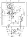
Figur 1 eine schematische Darstellung einer erfindungsgemäßen Hämodialyse-Geräteanordnung einschließlich einer Koaxial-Doppelport-Kupplung, durch die die Internfluidik des Basisgeräts mit der Externfluidik fluidisch verbunden ist, beim Vorfüllen, -
Figur 1a eine vergrößerte Darstellung des Details Ia derFigur 1 , -
Figur 2 die Hämodialyse-Geräteanordnung derFigur 1 während der Blutreinigung, -
Figur 3 die Hämodialyse-Geräteanordnung derFigur 1 während der Blutrückgabe, -
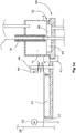
Figur 4 die Doppelport-Kupplung derFigur 1 während des Spülens der Basisgerät-seitigen stationären Doppelport-Buchse, -
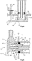
Figur 5 einen ersten Längsschnitt der Doppelport-Kupplung der Hämodialyse-Geräteanordnung derFigur 1 , -
Figur 6 einen zweiten Längsschnitt des Doppelport-Adapters 16 der Doppelport-Kupplung derFigur 5 , und -
Figur 7 eine Draufsicht auf den Doppelport-Adapter derFigur 6 . - In den Figuren ist eine Hämodialyse-Geräteanordnung 10 dargestellt, mit der an einem Patienten eine Blutreinigung vorgenommen werden kann. Die Hämodialyse-Geräteanordnung 10 ist strukturell aufgeteilt in ein stationäres Basisgerät 12, das ein geschlossenes Gerätegehäuse 20 aufweist, in dem eine Internfluidik angeordnet ist. Außerhalb des Gerätegehäuses 20 weist die Hämodialyse-Geräteanordnung 10 eine Externfluidik auf, die von einem Externfluidik-Set 14 gebildet wird, das im Wesentlichen aus einem Doppelport-Adapter 16 und einer Blutkreis-Leitungsanordnung 18 besteht. Das Externfluidik-Set 14 ist nicht wiederverwendbar, sondern ist als Einmal-Artikel ausgebildet, der nur für eine einzige Dialysebehandlung benutzt und danach entsorgt wird. Das Gerätegehäuse 20 ist grundsätzlich geschlossen ausgebildet und kann nicht ohne weiteres werkzeuglos geöffnet werden, sodass für den Benutzer und den Patienten kein unmittelbarer Zugriff auf die Internfluidik besteht.
- Das Gerätegehäuse 20 weist an seiner dem Bediener zugewandten Frontseite ein Gerätegehäuse-Interface 22 auf, das die Schnittstelle zwischen der Externfluidik und der Internfluidik darstellt und mehrere Fluid-Kupplungen für die fluidische Verbindung der Internfluidik mit der Externfluidik aufweist.
- Die Internfluidik und die Externfluidik sind unter anderem über eine Koaxial-Doppelport-Kupplung 15 fluidisch miteinander verbunden, durch die zwei einzelne fluidische Verbindungen zwischen der Internfluidik und der Externfluidik bedarfsweise hergestellt werden.
- Das Basisgerät 12 weist eine Substituatflüssigkeits-Quelle 24 auf, die vorliegend als interner Substituatflüssigkeits-Tank 25' ausgebildet ist, der eine Substituatflüssigkeit 25 enthält. Der Tank 25' kann alternativ auch außerhalb des Basisgerät- Gehäuses 20 angeordnet sein. Stromabwärts der Substituatflüssigkeits-Quelle 24 ist eine Substituatpumpe 31 angeordnet, durch die die Substituatflüssigkeit 25 zu einem Pumpziel gepumpt werden kann. Ferner weist das Basisgerät 12 innerhalb des Gerätegehäuses 20 eine Vorfüllflüssigkeits-Quelle 26 auf, die von einem Tank 27' gefüllt mit einer Vorfüllflüssigkeit 27 gebildet wird. Der Vorfüllflüssigkeits-Tank 27' kann alternativ auch außerhalb des Gerätegehäuses 20 angeordnet sein. Stromabwärts der Vorfüllflüssigkeit-Quelle 26 ist eine Vorfüllflüssigskeitspumpe 32 angeordnet, die die Vorfüllflüssigkeit 27 zu einem Vorfüllflüssigkeits-Ziel pumpen kann. Die Leitungen jeweils stromabwärts der beiden vorgenannten Pumpen 31,32 sind in einem Dreiwege-Quellenwahl-Ventil 36 zusammengeführt, dessen abgehender dritter Zweig zu der Koaxial-Doppelport-Kupplung 15 führt. Ferner weist das Basisgerät 12 einen Abfallflüssigkeitsbehälter 28' als Abfallflüssigkeits-Ziel 28 für Abfallflüssigkeit 29 auf.
- Das Externfluidik-Set 14 außerhalb des Gerätegehäuses 20 weist eine den extrakorporalen Blutkreis bildende und während der Blutreinigung blutführende Leitung 62 auf, die zwischen ihrem arteriellen Leitungsende 68 und ihrem venösen Leitungsende 69 von drei Leitungsabschnitten 62', 62", 62"' gebildet wird. Die blutführende Leitung 62 besteht aus Kunststoff, ist transparent und plastisch verformbar ausgebildet. Im an das Basisgerät 12 bzw. an das Gerätegehäuse-Interface 22 applizierten Zustand des Internfluidik-Sets 14 ist der erste Leitungsabschnitt 62' in die Blutpumpen-Mechanik 50' einer peristaltischen Blutpumpe 50 eingelegt, wobei die Blutpumpen-Mechanik 50' von einem Blutpumpen-Antriebsmotor 52 innerhalb des Gerätegehäuses 20 angetrieben wird. Stromabwärts der Blutpumpen-Mechanik 50 ist ein erster Substituatzugang 63 vorgesehen, der von einer arteriellen Kupplungsbuchse 121 gebildet wird. Stromabwärts des ersten Substituatzugangs 63 mündet die blutführende Leitung 62 in einen Dialysator 60, der eine großflächige Membran aufweist, durch die harnpflichtige Substanzen aus dem Blut auf die andere Seite der Membran in eine Dialyseflüssigkeit diffundieren können, die dem Dialysator 60 von einer Dialyseflüssigkeits-Versorgung 13 innerhalb des Gerätegehäuses 20 zur Verfügung gestellt wird.
- Stromabwärts des Dialysators 60 kann in einem zweiten Leitungsabschnitt 62" ein alternativer oder ein zusätzlicher zweiter Substituatzugang 64 vorgesehen sein, der von einer arteriellen Kupplungsbuchse 122 gebildet wird. Stromabwärts des zweiten Substituatzugangs 64 mündet der zweite Leitungsabschnitt 62" in eine Luftfalle 67, die einen dritten Substituatzugang 65 aufweist, der von einer arteriellen Kupplungsbuchse 123 gebildet wird. Stromabwärts der Luftfalle 67 ist im Verlauf des dritten Leitungsabschnitts 62"' ein Rückschlagventil 66 angeordnet, sodass eine Flüssigkeit in der blutführenden Leitung 62 stets nur in einer Richtung von dem arteriellen Leitungsende 68 zu dem venösen Leitungsende 69 fließen kann. Stromabwärts des Rückschlagventils 66 mündet der dritte Leitungsabschnitt 62"" in einen venösen Kupplungsstecker 130, der das venöse Leitungsende 69 bildet.
- In den
Figuren 1-3 ist ferner ein Patient 100 dargestellt, an dessen Arm ein arterieller Patientenzugang 102 mit einem arteriellen Kupplungsstecker 111 und ein venöser Patientenzugang 104 mit einem venösen Kupplungsstecker 131 appliziert ist. - Die Koaxial-Doppelport-Kupplung 15 besteht aus einem internfluidischen Teil und einem externfluidischen Teil. Der internfluidische Teil der Koaxial-Doppelport-Kupplung 15 definiert eine Basisgerät-seitige Doppelport-Buchse 70, die eine fluidische Zentralleitung 76 und eine die Zentralleitung 76 ringförmig umgebende koaxiale Ringleitung 74 aufweist. Der Externfluidik-Teil der Koaxial-Doppelport-Kupplung 15 wird von einem Doppelport-Adapter 16 gebildet, der von einem Kunststoff-AdapterKörper 16' definiert ist, der wiederum eine fluidische Zentralleitung 86 und eine die Zentralleitung 86 ringförmig umgebende koaxiale Ringleitung 84 bildet.
- Wenn der Doppelport-Adapter 16 fluidisch appliziert ist, wie in den
Figuren 1-3 und5 dargestellt ist, sind die beiden Ringleitungen 74, 84 und die beiden Zentralleitungen 76, 86 jeweils fluidisch miteinander verbunden, so dass zwei voneinander unabhängige fluidische Verbindungen zwischen der Internfluidik und der Externfluidik hergestellt sind. Die Stecker-Zentralleitung 86 mündet in eine flexible Stecker-Anschlussleitung 81, die an ihrem Leitungsende einen arteriellen Kupplungsstecker 110 aufweist, der mit allen arteriellen Kupplungsbuchsen 120-123 aufgrund seiner mechanischen Kodierung grundsätzlich zusammenkuppelbar ist. Die Stecker-Ringleitung 84 mündet fluidisch in einen venösen Kupplungsstecker 130, der mit der venösen Kupplungsbuchse 140 zusammenkuppelbar ist. - Unmittelbar benachbart zu der Doppelport-Kupplungsbuchse 70 ist geräteseitig an dem Interface 22 ein schwenkhebelartiges Verriegelungsmittel 40 angeordnet. Das Verriegelungsmittel 40 weist eine schwenkbare und axial verschiebbare Verriegelungsmittel-Welle 46 auf, die außenseitig von einem stationären Positionssensor 44 lesbare Markierungen aufweist, so dass der Positionssensor 44 drei verschiedene Positionen des Verriegelungsmittels 40 zuverlässig detektieren kann. Der Verriegelungsmittel-Welle 46 ist eine Vorspannfeder 47 beispielsweise koaxial zugeordnet, sodass die Welle 46 in proximaler Richtung axial vorgespannt ist. Die drei möglichen Positionen des Verriegelungsmittels 40 sind die funktionslose Position, die Verriegelungsposition und die Spülposition, die im Folgenden noch erläutert werden.
- An der Verriegelungsmittel-Welle 46 schließt sich ein hebelartiges Gebilde an, das eine deckelartige Flussumkehr-Kappe 42 und ein Verriegelungsteil 41 bildet. In der Verriegelungsposition des Verriegelungsmittels 40 ist der Doppelport-Kupplungsstecker 80 in seiner Verriegelungsposition durch das Verriegelungsteil 41 blockiert, sodass der Doppelport-Kupplungsstecker 80 nicht versehentlich von der Doppelport-Kupplungsbuchse 70 entfernt werden kann.
- Wie in der
Figur 5 dargestellt ist, ist an der Innenseite der äußeren zylindrischen Buchsenwand 78 der Kupplungsbuchse in einer zirkulären Dichtring-Nut 79 ein Dichtring 77 angeordnet, der die zuverlässige fluiddichte Abdichtung mit der korrespondierenden zylindrischen Steckerwand 88 sicherstellt. Im zusammengekuppelten Zustand ist ferner die Stecker-Zentralleitung 86 fluiddicht in die Buchsen-Zentralleitung 76 eingesteckt, wobei die beiden Zentralleitungsenden leicht konisch angeschrägt ausgebildet sind und fluiddicht aneinander anliegen. - Die Doppelport-Kupplungsbuchse 70 und der Doppelport-Kupplungsstecker 80 weisen eine miteinander korrespondierende Bajonettverriegelung 72 auf, die von einem steckerseitigen Bajonettsteg 72", der nach radial außen abragt, und einem buchsenseitigen Bajonettring 72' gebildet wird. Im zusammengekuppelten Zustand hintergreift der Bajonettsteg 72" den Bajonettring 72', wie in
Fig. 5 dargestellt. - In der
Figur 1 ist die Hämodialyse-Geräteanordnung 10 beim Vorfüllen dargestellt: Der arterielle Kupplungsstecker 110 und der venöse Kupplungsstecker 130 des Doppelport-Adapters 16 sind mit der korrespondierenden arteriellen Kupplungsbuchse 120 des arteriellen Leitungsendes 68 und mit der korrespondierenden venösen Kupplungsbuchse 140 des venösen Leitungsendes 69 verkuppelt und fluidisch verbunden. Die Vorfüllflüssigkeit 27 wird durch die aktivierte Vorfüllflüssigkeitspumpe 32 und die ebenfalls aktivierte Blutpumpe 50 aus einer Richtung in die Blutleitung 62 gepumpt, sodass die Blutleitung 62 schließlich vollständig mit Vorfüllflüssigkeit gefüllt ist. Überschüssige Vorfüllflüssigkeit fließt schließlich in den Abfallflüssigkeitsbehälter 28 ab. - Alternativ kann die Blutleitung 62 beidseitig gefüllt werden. Hierzu wird das Synchronfüllungs-Ventil 37 so umgeschaltet, dass die Vorfüllflüssigkeit sowohl von dem arteriellen Leitungsende 68 als auch von dem venösen Leitungsende 69 aus in die Blutleitung 62 gepumpt wird. Dabei pumpt die Blutpumpe 50 ungefähr mit der halben Flussleistung wie die Vorfüllflüssigkeitspumpe 32, wobei die Luft aus der Blutleitung 62 beispielsweise über den Substituatzugang 65 der Luftfalle 67 entweicht.
- Sobald die Blutleitung 62 vollständig mit Vorfüllflüssigkeit gefüllt ist, werden die beiden Pumpen 32,50 angehalten, und werden die beiden Leitungsenden 68,69 an dem Patienten 100 appliziert, wie in
Figur 2 dargestellt. Ferner wird der arterielle Kupplungsstecker 110 der Koaxial-Doppelkupplung 15 an einen Substituatzugang 63 appliziert, so dass bei Bedarf mit aktivierter Substituatpumpe 31 Substituatflüssigkeit 25 aus der Substituatflüssigkeits-Quelle 24 über den Substituatzugang 63 in die Blutleitung 62 eingeleitet werden kann. - Nach Abschluss der eigentlichen Blutreinigung wird die arterielle Kupplungsbuchse 120 des arteriellen Leitungsendes 68 der Blutkreis-Leitungsanordnung 18 wieder an den arteriellen Kupplungsstecker 110 der Koaxial-Doppelkupplung 15 angeschlossen. Die Substituatflüssigkeits-Pumpe 31 wird aktiviert, sodass die Substituatflüssigkeit 25 von dem arteriellen Leitungsende 68 aus in die Blutleitung 62 gepumpt wird, wodurch das Blut aus der Blutleitung 62 über das venöse Leitungsende 69 zurück in den Patienten 100 gepumpt wird.
- Nach Abschluss der Dialysebehandlung wird der Doppelport-Adapter 16 entfernt und entsorgt. Anschließend wird das Verriegelungsmittel 40 so verschwenkt, dass die Flussumkehr-Kappe 42 die Öffnung der Doppelport-Kupplungsbuchse 70 vollständig verschließt. Anschließend kann eine Spülung und/oder eine Desinfektion der Doppelport-Kupplungsbuchse 70 erfolgen, indem eine Spülflüssigkeit, beispielsweise die Vorfüllflüssigkeit 27, zu der Doppelport-Kupplungsbuchse 70 gepumpt wird, die von dort zu dem Abfallflüssigkeitsbehälter 28 abfließt.
- Während aller Phasen kann über einen geräteinternen Drucksensor 34 im Zulauf zu der Doppelport-Kupplungsbuchse 70 geprüft werden, ob die Doppelportkupplung 15 fluiddicht verkuppelt ist. Dies kann ggf. auch mit weiteren Drucksensoren am Externfluidik-Set 14 erfolgen.
- 10 Hämodialyse-Geräteanordnung
- 12 Basisgerät
- 13 Dialyseflüssigkeits-Versorgung
- 14 Externfluidik-Set
- 15 Koaxial-Doppelportkupplung
- 16 Doppelport-Adapter
- 16' Adapterkörper
- 18 Blutkreis-Leitungsanordnung
- 20 Gerätegehäuse
- 22 Gerätegehäuse-Interface
- 24 Substituatflüssigkeits-Quelle
- 25 Substituatflüssigkeit
- 26 Vorfüllflüssigkeits-Quelle
- 27 Vorfüllflüssigkeit
- 28 Abfallflüssigkeitsbehälter
- 29 Abfallflüssigkeit
- 31 Substituatpumpe
- 32 Vorfüllflüssigkeitspumpe
- 34 Drucksensor
- 36 Quellenwahl-Ventil
- 37 Synchronfüllungs-Ventil
- 40 Verriegelungsmittel
- 41 Verriegelungsteil
- 42 Flussumkehr-Kappe
- 44 Positionsdetektor
- 46 Verriegelungsmittel-Welle
- 47 Vorspannfeder
- 50 Blutpumpe
- 50' Blutpumpen-Mechanik
- 52 Blutpumpen-Antriebsmotor
- 60 Dialysator
- 62 Blutleitung
- 62',62", 62"' Leitungsabschnitt
- 63 Substituatzugang
- 64 Substituatzugang
- 65 Substituatzugang
- 66 Rückschlagventil
- 67 Luftfalle
- 68 arterielles Leitungsende
- 69 venöses Leitungsende
- 70 Doppelport-Kupplungsbuchse
- 72 Bajonettverriegelung
- 72', 72" Verriegelungssteg, Verriegelungsnase
- 74 Buchsen-Ringleitung
- 76 Buchsen-Zentralleitung
- 77 Dichtring
- 78 Buchsenwand
- 79 Dichtring-Nut
- 80 Doppelport-Kupplungsstecker
- 81 Stecker-Anschlussleitung
- 84 Stecker-Ringleitung
- 86 Stecker-Zentralleitung
- 100 Patientenkörper
- 102 arterieller Patientenzugang
- 104 venöser Patientenzugang
- 110 arterieller Kupplungsstecker
- 111 arterieller Kupplungsstecker
- 120 arterielle Kupplungsbuchse
- 121 arterielle Kupplungsbuchse
- 122 arterielle Kupplungsbuchse
- 123 arterielle Kupplungsbuchse
- 130 venöser Kupplungsstecker
- 131 venöser Kupplungsstecker
- 140 venöse Kupplungsbuchse
Claims (11)
- Hämodialyse-Geräteanordnung (10) mit einem Basisgerät (12), das ein Gerätegehäuse (20) und eine Internfluidik innerhalb des Gerätegehäuses (20) aufweist, und mit einem eine Externfluidik bildenden Externfluidik-Set (14) außerhalb des Gerätegehäuses (20), das über kuppelbare Fluidkupplungen fluidisch mit dem Basisgerät (12) verbunden ist,
wobei eine fluidische Koaxial-Doppelport-Kupplung (15) vorgesehen ist, die von einer Basisgerät-seitigen stationären Doppelport-Buchse (70) und einem korrespondierenden Externfluidik-Set-seitigen Doppelport-Stecker (80) gebildet ist, der auf die Doppelport-Buchse (70) lösbar aufgesteckt ist, wobei sowohl der Doppelport-Stecker (80) als auch die Doppelport-Buchse (70) jeweils eine fluidische Zentralleitung (86,76) und eine die Zentralleitung (86, 76) jeweils ringförmig umgebende koaxiale fluidische Ringleitung (84, 74) aufweisen. - Hämodialyse-Geräteanordnung (10) nach Anspruch 1, wobei geräteseitig ein Verriegelungsmittel (40) vorgesehen ist, wobei das Verriegelungsmittel (40) in seiner Verriegelungsposition den Doppelport-Stecker (80) in seiner Kupplungsposition auf der stationären Doppelport-Buchse (70) blockiert.
- Hämodialyse-Geräteanordnung (10) nach Anspruch 2, wobei das Verriegelungsmittel (40) eine Flussumkehr-Kappe (42) aufweist, die bei nicht angekoppeltem Doppelport-Stecker (80) in einer Spülposition des Verriegelungsmittels (40) die Doppelport-Buchse (70) derart verschließt, dass die Buchsen-Zentralleitung (76) fluidisch verbunden ist mit der Buchsen-Ringleitung (74).
- Hämodialyse-Geräteanordnung (10) nach einem der vorangegangenen Ansprüche, wobei dem Verriegelungsmittel (40) ein Positionsdetektor (44) zugeordnet ist, der die Verriegelungsposition und/oder die Spülposition des Verriegelungsmittels (40) detektiert.
- Hämodialyse-Geräteanordnung (10) nach einem der vorangegangenen Ansprüche, wobei dem Basisgerät (12) fluidisch eine Substituatflüssigkeits-Quelle (24) zugeordnet ist, die fluidisch mit der Buchsen-Ringleitung (74) oder der Buchsen-Zentralleitung verbunden ist.
- Hämodialyse-Geräteanordnung (10) nach Anspruch 5, wobei das Basisgerät (12) eine interne Substituatpumpe (31) aufweist, die die Substituatflüssigkeit (25) von der Substituatflüssigkeits-Quelle (24) zu der Doppelport-Kupplung (15) pumpt.
- Hämodialyse-Geräteanordnung (10) nach einem der vorangegangenen Ansprüche, wobei dem Basisgerät (12) ein Abfallflüssigkeits-Ziel (28) zugeordnet ist, das fluidisch mit der Buchsen-Zentralleitung (76) oder der Buchsen-Ringleitung verbunden ist.
- Hämodialyse-Geräteanordnung (10) nach einem der vorangegangenen Ansprüche, wobei das Externfluidik-Set (14) einen Doppelport-Adapter (16) mit dem Doppelport-Stecker (80) und eine separate Blutkreis-Leitungsanordnung (18) aufweist, wobei die Blutkreis-Leitungsanordnung (18) an ihrem arteriellen und ihrem venösen Leitungsende (68, 69) eine arterielle Kupplungsbuchse (120) und eine venöse Kupplungsbuchse (140) aufweist, und wobei der Doppelport-Adapter (16) einen korrespondierenden arteriellen Kupplungsstecker (110) aufweist, der fluidisch mit der Substituatflüssigkeits-Quelle (24) verbunden ist, und einen korrespondierenden venösen Kupplungsstecker (130) aufweist, der fluidisch mit dem Abfallflüssigkeitsbehälter (28) verbunden ist.
- Hämodialyse-Geräteanordnung (10) nach einem der vorangegangenen Ansprüche, wobei die Blutkreis-Leitungsanordnung (18) einen separaten Substituatzugang (63, 64, 65) zwischen den beiden Blutkreis-Leitungsenden (68, 69) aufweist, der von einer arteriellen Kupplungsbuchse (121, 122, 123) gebildet wird.
- Hämodialyse-Geräteanordnung (10) nach einem der vorangegangenen Ansprüche, wobei stromaufwärts des venösen Leitungsendes (69) ein Rückschlagventil (66) angeordnet ist.
- Doppelport-Adapter (18) mit den sich auf diesen beziehenden Merkmalen des Anspruchs 8 für eine Hämodialyse-Geräteanordnung mit den sich auf diese beziehenden Merkmalen einer der vorangegangenen Ansprüche.
Priority Applications (2)
| Application Number | Priority Date | Filing Date | Title |
|---|---|---|---|
| EP18192552.0A EP3620190B1 (de) | 2018-09-04 | 2018-09-04 | Hämodialyse-geräteanordnung |
| ES18192552T ES2954281T3 (es) | 2018-09-04 | 2018-09-04 | Disposición de aparatos de hemodiálisis |
Applications Claiming Priority (1)
| Application Number | Priority Date | Filing Date | Title |
|---|---|---|---|
| EP18192552.0A EP3620190B1 (de) | 2018-09-04 | 2018-09-04 | Hämodialyse-geräteanordnung |
Publications (3)
| Publication Number | Publication Date |
|---|---|
| EP3620190A1 true EP3620190A1 (de) | 2020-03-11 |
| EP3620190B1 EP3620190B1 (de) | 2023-06-07 |
| EP3620190C0 EP3620190C0 (de) | 2023-06-07 |
Family
ID=63517679
Family Applications (1)
| Application Number | Title | Priority Date | Filing Date |
|---|---|---|---|
| EP18192552.0A Active EP3620190B1 (de) | 2018-09-04 | 2018-09-04 | Hämodialyse-geräteanordnung |
Country Status (2)
| Country | Link |
|---|---|
| EP (1) | EP3620190B1 (de) |
| ES (1) | ES2954281T3 (de) |
Cited By (2)
| Publication number | Priority date | Publication date | Assignee | Title |
|---|---|---|---|---|
| CN113476675A (zh) * | 2021-06-09 | 2021-10-08 | 汕头大学医学院第一附属医院 | 一种双滤式血液净化透析装置 |
| CN114470376A (zh) * | 2022-01-26 | 2022-05-13 | 重庆山外山血液净化技术股份有限公司 | 一种血液净化用a、b干粉在线联机配置装置 |
Citations (2)
| Publication number | Priority date | Publication date | Assignee | Title |
|---|---|---|---|---|
| DE102010032179A1 (de) * | 2010-07-23 | 2012-01-26 | Fresenius Medical Care Deutschland Gmbh | Konnektor, medizintechnische Behandlungsvorrichtung, medizintechnische Funktionseinrichtung sowie Verfahren |
| US20170021086A1 (en) * | 2015-07-24 | 2017-01-26 | Medtronic, Inc. | Dialysis priming steps using an infusate caddy |
-
2018
- 2018-09-04 ES ES18192552T patent/ES2954281T3/es active Active
- 2018-09-04 EP EP18192552.0A patent/EP3620190B1/de active Active
Patent Citations (2)
| Publication number | Priority date | Publication date | Assignee | Title |
|---|---|---|---|---|
| DE102010032179A1 (de) * | 2010-07-23 | 2012-01-26 | Fresenius Medical Care Deutschland Gmbh | Konnektor, medizintechnische Behandlungsvorrichtung, medizintechnische Funktionseinrichtung sowie Verfahren |
| US20170021086A1 (en) * | 2015-07-24 | 2017-01-26 | Medtronic, Inc. | Dialysis priming steps using an infusate caddy |
Cited By (3)
| Publication number | Priority date | Publication date | Assignee | Title |
|---|---|---|---|---|
| CN113476675A (zh) * | 2021-06-09 | 2021-10-08 | 汕头大学医学院第一附属医院 | 一种双滤式血液净化透析装置 |
| CN114470376A (zh) * | 2022-01-26 | 2022-05-13 | 重庆山外山血液净化技术股份有限公司 | 一种血液净化用a、b干粉在线联机配置装置 |
| CN114470376B (zh) * | 2022-01-26 | 2024-05-03 | 重庆山外山血液净化技术股份有限公司 | 一种血液净化用a、b干粉在线联机配置装置 |
Also Published As
| Publication number | Publication date |
|---|---|
| EP3620190B1 (de) | 2023-06-07 |
| ES2954281T3 (es) | 2023-11-21 |
| EP3620190C0 (de) | 2023-06-07 |
Similar Documents
| Publication | Publication Date | Title |
|---|---|---|
| EP3061489B1 (de) | Konnektor für einen dialysator | |
| DE102010007464B4 (de) | Medizinische Funktionseinrichtung, Behandlungsvorrichtung sowie Verfahren | |
| EP1539271B1 (de) | Blutbehandlungsvorrichtung mit blutrückgabe | |
| DE102012005187B4 (de) | Medizinische Vorrichtung mit einer Buchsen-Einheit zum Anschluss einer Vorrichtung zur Bereitstellung von medizinischen Flüssigkeiten | |
| DE69630887T2 (de) | Blutleitungssatz für die dialyse | |
| EP2819631B1 (de) | Spike mit rückschlagventilfunktion sowie befüllvorrichtung eines flüssigkeitssystems mit spike | |
| EP2421585B1 (de) | Verbindungseinrichtung und verfahren zum konnektieren wenigstens zweier fluidführender medizintechnischer systeme, sowie medizintechnische vorrichtung | |
| DE3413860A1 (de) | Medizinische fluessigkeits-probenentnahmevorrichtung | |
| EP2954911B1 (de) | Dialysemaschinen-integrierte substituatpumpe | |
| EP2825249A2 (de) | Medizinische behandlungsvorrichtung und vorrichtung zur bereitstellung von medizinischen behandlungsflüssigkeiten sowie vorrichtung zum befüllen einer vorrichtung zur bereitstellung von medizinischen flüssigkeiten | |
| WO2023083767A1 (de) | Dialysegerät mit konnektionseinheit | |
| EP2595671B1 (de) | Spülleitung, medizintechnische funktionseinrichtung, medizintechnische behandlungsvorrichtung sowie verfahren | |
| DE102006022122A1 (de) | Verfahren zur Füllung und Spülung eines Blutschlauchsatzes | |
| DE4208054C2 (de) | Leitungs-System zum Spülen eines extrakorporalen Kreislaufs bei der Hämodialyse, Hämofiltration und Hämodiafiltration | |
| EP3620190B1 (de) | Hämodialyse-geräteanordnung | |
| WO2014170380A1 (de) | Befüllvorrichtung eines flüssigkeitssystems | |
| EP2583700B1 (de) | Starten einer Hämodialyse | |
| DE3447989C2 (de) | ||
| EP0203513B1 (de) | Medizinische Beutelanordnung | |
| EP4291864A1 (de) | Vorrichtung für eine extrakorporale blutbehandlung | |
| DE10042067A1 (de) | Anordnung mit Peritonielkatheter und Schlauchsystem | |
| DE102023121611A1 (de) | Medizinisches Fluidleitungssystem mit Zuspritzanschluss | |
| DE2229411C3 (de) | Vorrichtung zum Spülen von Körperhöhlen | |
| DE8106491U1 (de) | Infusionsbeutel | |
| DE102024123176A1 (de) | Medizinische Behandlungsvorrichtung |
Legal Events
| Date | Code | Title | Description |
|---|---|---|---|
| PUAI | Public reference made under article 153(3) epc to a published international application that has entered the european phase |
Free format text: ORIGINAL CODE: 0009012 |
|
| STAA | Information on the status of an ep patent application or granted ep patent |
Free format text: STATUS: THE APPLICATION HAS BEEN PUBLISHED |
|
| AK | Designated contracting states |
Kind code of ref document: A1 Designated state(s): AL AT BE BG CH CY CZ DE DK EE ES FI FR GB GR HR HU IE IS IT LI LT LU LV MC MK MT NL NO PL PT RO RS SE SI SK SM TR |
|
| AX | Request for extension of the european patent |
Extension state: BA ME |
|
| STAA | Information on the status of an ep patent application or granted ep patent |
Free format text: STATUS: REQUEST FOR EXAMINATION WAS MADE |
|
| 17P | Request for examination filed |
Effective date: 20200909 |
|
| RBV | Designated contracting states (corrected) |
Designated state(s): AL AT BE BG CH CY CZ DE DK EE ES FI FR GB GR HR HU IE IS IT LI LT LU LV MC MK MT NL NO PL PT RO RS SE SI SK SM TR |
|
| RAP1 | Party data changed (applicant data changed or rights of an application transferred) |
Owner name: D.MED CONSULTING GMBH |
|
| RAP1 | Party data changed (applicant data changed or rights of an application transferred) |
Owner name: NIPRO CORPORATION |
|
| GRAP | Despatch of communication of intention to grant a patent |
Free format text: ORIGINAL CODE: EPIDOSNIGR1 |
|
| STAA | Information on the status of an ep patent application or granted ep patent |
Free format text: STATUS: GRANT OF PATENT IS INTENDED |
|
| RIC1 | Information provided on ipc code assigned before grant |
Ipc: A61M 1/36 20060101ALI20220907BHEP Ipc: A61M 1/14 20060101AFI20220907BHEP |
|
| INTG | Intention to grant announced |
Effective date: 20220921 |
|
| RAP1 | Party data changed (applicant data changed or rights of an application transferred) |
Owner name: NIPRO MEDICAL EUROPE N.V. Owner name: NIPRO CORPORATION |
|
| GRAS | Grant fee paid |
Free format text: ORIGINAL CODE: EPIDOSNIGR3 |
|
| GRAA | (expected) grant |
Free format text: ORIGINAL CODE: 0009210 |
|
| STAA | Information on the status of an ep patent application or granted ep patent |
Free format text: STATUS: THE PATENT HAS BEEN GRANTED |
|
| AK | Designated contracting states |
Kind code of ref document: B1 Designated state(s): AL AT BE BG CH CY CZ DE DK EE ES FI FR GB GR HR HU IE IS IT LI LT LU LV MC MK MT NL NO PL PT RO RS SE SI SK SM TR |
|
| REG | Reference to a national code |
Ref country code: GB Ref legal event code: FG4D Free format text: NOT ENGLISH |
|
| REG | Reference to a national code |
Ref country code: CH Ref legal event code: EP Ref country code: AT Ref legal event code: REF Ref document number: 1573019 Country of ref document: AT Kind code of ref document: T Effective date: 20230615 Ref country code: DE Ref legal event code: R096 Ref document number: 502018012274 Country of ref document: DE |
|
| U01 | Request for unitary effect filed |
Effective date: 20230704 |
|
| U07 | Unitary effect registered |
Designated state(s): AT BE BG DE DK EE FI FR IT LT LU LV MT NL PT SE SI Effective date: 20230712 |
|
| REG | Reference to a national code |
Ref country code: LT Ref legal event code: MG9D |
|
| U20 | Renewal fee for the european patent with unitary effect paid |
Year of fee payment: 6 Effective date: 20230914 |
|
| PG25 | Lapsed in a contracting state [announced via postgrant information from national office to epo] |
Ref country code: NO Free format text: LAPSE BECAUSE OF FAILURE TO SUBMIT A TRANSLATION OF THE DESCRIPTION OR TO PAY THE FEE WITHIN THE PRESCRIBED TIME-LIMIT Effective date: 20230907 |
|
| REG | Reference to a national code |
Ref country code: ES Ref legal event code: FG2A Ref document number: 2954281 Country of ref document: ES Kind code of ref document: T3 Effective date: 20231121 |
|
| PG25 | Lapsed in a contracting state [announced via postgrant information from national office to epo] |
Ref country code: RS Free format text: LAPSE BECAUSE OF FAILURE TO SUBMIT A TRANSLATION OF THE DESCRIPTION OR TO PAY THE FEE WITHIN THE PRESCRIBED TIME-LIMIT Effective date: 20230607 Ref country code: HR Free format text: LAPSE BECAUSE OF FAILURE TO SUBMIT A TRANSLATION OF THE DESCRIPTION OR TO PAY THE FEE WITHIN THE PRESCRIBED TIME-LIMIT Effective date: 20230607 Ref country code: GR Free format text: LAPSE BECAUSE OF FAILURE TO SUBMIT A TRANSLATION OF THE DESCRIPTION OR TO PAY THE FEE WITHIN THE PRESCRIBED TIME-LIMIT Effective date: 20230908 |
|
| PG25 | Lapsed in a contracting state [announced via postgrant information from national office to epo] |
Ref country code: SK Free format text: LAPSE BECAUSE OF FAILURE TO SUBMIT A TRANSLATION OF THE DESCRIPTION OR TO PAY THE FEE WITHIN THE PRESCRIBED TIME-LIMIT Effective date: 20230607 |
|
| PG25 | Lapsed in a contracting state [announced via postgrant information from national office to epo] |
Ref country code: IS Free format text: LAPSE BECAUSE OF FAILURE TO SUBMIT A TRANSLATION OF THE DESCRIPTION OR TO PAY THE FEE WITHIN THE PRESCRIBED TIME-LIMIT Effective date: 20231007 |
|
| PG25 | Lapsed in a contracting state [announced via postgrant information from national office to epo] |
Ref country code: SM Free format text: LAPSE BECAUSE OF FAILURE TO SUBMIT A TRANSLATION OF THE DESCRIPTION OR TO PAY THE FEE WITHIN THE PRESCRIBED TIME-LIMIT Effective date: 20230607 Ref country code: SK Free format text: LAPSE BECAUSE OF FAILURE TO SUBMIT A TRANSLATION OF THE DESCRIPTION OR TO PAY THE FEE WITHIN THE PRESCRIBED TIME-LIMIT Effective date: 20230607 Ref country code: RO Free format text: LAPSE BECAUSE OF FAILURE TO SUBMIT A TRANSLATION OF THE DESCRIPTION OR TO PAY THE FEE WITHIN THE PRESCRIBED TIME-LIMIT Effective date: 20230607 Ref country code: IS Free format text: LAPSE BECAUSE OF FAILURE TO SUBMIT A TRANSLATION OF THE DESCRIPTION OR TO PAY THE FEE WITHIN THE PRESCRIBED TIME-LIMIT Effective date: 20231007 Ref country code: CZ Free format text: LAPSE BECAUSE OF FAILURE TO SUBMIT A TRANSLATION OF THE DESCRIPTION OR TO PAY THE FEE WITHIN THE PRESCRIBED TIME-LIMIT Effective date: 20230607 |
|
| PG25 | Lapsed in a contracting state [announced via postgrant information from national office to epo] |
Ref country code: PL Free format text: LAPSE BECAUSE OF FAILURE TO SUBMIT A TRANSLATION OF THE DESCRIPTION OR TO PAY THE FEE WITHIN THE PRESCRIBED TIME-LIMIT Effective date: 20230607 |
|
| REG | Reference to a national code |
Ref country code: DE Ref legal event code: R097 Ref document number: 502018012274 Country of ref document: DE |
|
| PLBE | No opposition filed within time limit |
Free format text: ORIGINAL CODE: 0009261 |
|
| STAA | Information on the status of an ep patent application or granted ep patent |
Free format text: STATUS: NO OPPOSITION FILED WITHIN TIME LIMIT |
|
| REG | Reference to a national code |
Ref country code: CH Ref legal event code: PL |
|
| 26N | No opposition filed |
Effective date: 20240308 |
|
| PG25 | Lapsed in a contracting state [announced via postgrant information from national office to epo] |
Ref country code: MC Free format text: LAPSE BECAUSE OF FAILURE TO SUBMIT A TRANSLATION OF THE DESCRIPTION OR TO PAY THE FEE WITHIN THE PRESCRIBED TIME-LIMIT Effective date: 20230607 |
|
| REG | Reference to a national code |
Ref country code: IE Ref legal event code: MM4A |
|
| PG25 | Lapsed in a contracting state [announced via postgrant information from national office to epo] |
Ref country code: IE Free format text: LAPSE BECAUSE OF NON-PAYMENT OF DUE FEES Effective date: 20230904 |
|
| PG25 | Lapsed in a contracting state [announced via postgrant information from national office to epo] |
Ref country code: CH Free format text: LAPSE BECAUSE OF NON-PAYMENT OF DUE FEES Effective date: 20230930 |
|
| PG25 | Lapsed in a contracting state [announced via postgrant information from national office to epo] |
Ref country code: IE Free format text: LAPSE BECAUSE OF NON-PAYMENT OF DUE FEES Effective date: 20230904 Ref country code: CH Free format text: LAPSE BECAUSE OF NON-PAYMENT OF DUE FEES Effective date: 20230930 |
|
| U20 | Renewal fee for the european patent with unitary effect paid |
Year of fee payment: 7 Effective date: 20240925 |
|
| PG25 | Lapsed in a contracting state [announced via postgrant information from national office to epo] |
Ref country code: CY Free format text: LAPSE BECAUSE OF FAILURE TO SUBMIT A TRANSLATION OF THE DESCRIPTION OR TO PAY THE FEE WITHIN THE PRESCRIBED TIME-LIMIT; INVALID AB INITIO Effective date: 20180904 |
|
| PG25 | Lapsed in a contracting state [announced via postgrant information from national office to epo] |
Ref country code: HU Free format text: LAPSE BECAUSE OF FAILURE TO SUBMIT A TRANSLATION OF THE DESCRIPTION OR TO PAY THE FEE WITHIN THE PRESCRIBED TIME-LIMIT; INVALID AB INITIO Effective date: 20180904 |
|
| PGFP | Annual fee paid to national office [announced via postgrant information from national office to epo] |
Ref country code: GB Payment date: 20250923 Year of fee payment: 8 |
|
| U20 | Renewal fee for the european patent with unitary effect paid |
Year of fee payment: 8 Effective date: 20250923 |
|
| PG25 | Lapsed in a contracting state [announced via postgrant information from national office to epo] |
Ref country code: TR Free format text: LAPSE BECAUSE OF FAILURE TO SUBMIT A TRANSLATION OF THE DESCRIPTION OR TO PAY THE FEE WITHIN THE PRESCRIBED TIME-LIMIT Effective date: 20230607 |
|
| PGFP | Annual fee paid to national office [announced via postgrant information from national office to epo] |
Ref country code: ES Payment date: 20251020 Year of fee payment: 8 |