EP3620196A1 - Beatmungsvorrichtung - Google Patents
Beatmungsvorrichtung Download PDFInfo
- Publication number
- EP3620196A1 EP3620196A1 EP19192229.3A EP19192229A EP3620196A1 EP 3620196 A1 EP3620196 A1 EP 3620196A1 EP 19192229 A EP19192229 A EP 19192229A EP 3620196 A1 EP3620196 A1 EP 3620196A1
- Authority
- EP
- European Patent Office
- Prior art keywords
- cuff
- water
- tube
- active substance
- ventilation device
- Prior art date
- Legal status (The legal status is an assumption and is not a legal conclusion. Google has not performed a legal analysis and makes no representation as to the accuracy of the status listed.)
- Granted
Links
Images
Classifications
-
- A—HUMAN NECESSITIES
- A61—MEDICAL OR VETERINARY SCIENCE; HYGIENE
- A61M—DEVICES FOR INTRODUCING MEDIA INTO, OR ONTO, THE BODY; DEVICES FOR TRANSDUCING BODY MEDIA OR FOR TAKING MEDIA FROM THE BODY; DEVICES FOR PRODUCING OR ENDING SLEEP OR STUPOR
- A61M16/00—Devices for influencing the respiratory system of patients by gas treatment, e.g. ventilators; Tracheal tubes
- A61M16/04—Tracheal tubes
-
- A—HUMAN NECESSITIES
- A61—MEDICAL OR VETERINARY SCIENCE; HYGIENE
- A61M—DEVICES FOR INTRODUCING MEDIA INTO, OR ONTO, THE BODY; DEVICES FOR TRANSDUCING BODY MEDIA OR FOR TAKING MEDIA FROM THE BODY; DEVICES FOR PRODUCING OR ENDING SLEEP OR STUPOR
- A61M16/00—Devices for influencing the respiratory system of patients by gas treatment, e.g. ventilators; Tracheal tubes
- A61M16/04—Tracheal tubes
- A61M16/0434—Cuffs
- A61M16/0436—Special fillings therefor
-
- A—HUMAN NECESSITIES
- A61—MEDICAL OR VETERINARY SCIENCE; HYGIENE
- A61M—DEVICES FOR INTRODUCING MEDIA INTO, OR ONTO, THE BODY; DEVICES FOR TRANSDUCING BODY MEDIA OR FOR TAKING MEDIA FROM THE BODY; DEVICES FOR PRODUCING OR ENDING SLEEP OR STUPOR
- A61M16/00—Devices for influencing the respiratory system of patients by gas treatment, e.g. ventilators; Tracheal tubes
- A61M16/04—Tracheal tubes
- A61M16/0434—Cuffs
- A61M16/0443—Special cuff-wall materials
-
- A—HUMAN NECESSITIES
- A61—MEDICAL OR VETERINARY SCIENCE; HYGIENE
- A61M—DEVICES FOR INTRODUCING MEDIA INTO, OR ONTO, THE BODY; DEVICES FOR TRANSDUCING BODY MEDIA OR FOR TAKING MEDIA FROM THE BODY; DEVICES FOR PRODUCING OR ENDING SLEEP OR STUPOR
- A61M16/00—Devices for influencing the respiratory system of patients by gas treatment, e.g. ventilators; Tracheal tubes
- A61M16/04—Tracheal tubes
- A61M16/0475—Tracheal tubes having openings in the tube
- A61M16/0477—Tracheal tubes having openings in the tube with incorporated means for delivering or removing fluids
- A61M16/0481—Tracheal tubes having openings in the tube with incorporated means for delivering or removing fluids through the cuff wall
Definitions
- the present invention relates to a ventilation device, in particular an endotracheal tube or a tracheostomy tube, with a tube and a cuff which is tightly connected to the outside of the tube and which is in fluid communication with a control balloon or can be connected to it.
- Ventilation devices are inserted into a patient's trachea to provide the patient with air or breathing gas.
- the cannula tube can be inserted into a patient's trachea through an opening (tracheostoma) artificially created in a patient's throat below the larynx area or via the mouth and pharynx.
- the central lumen of the cannula tube is used for the passage of air or breathing gas.
- the fillable cuff on the outer circumference of the cannula tube serves to seal the trachea in the volume outside the cannula tube.
- a cuff usually consists of an inflatable, flexible hose section with a very small wall thickness, the end sections of which rest on the outside of the cannula tube and are fixed there in a sealed manner.
- the cuff is at least in a section between its ends compared to the cannula tube or is inflatable to such an oversize.
- the initially unfilled cuff lies closely against the outside of the cannula tube and is inflated after insertion, with little pressure until it comes into contact with the wall of the trachea sealingly along its circumference, but with as little pressure as possible.
- the low pressure is intended to prevent the cuff from pressing against the wall of the trachea, which can interrupt the blood supply to the tracheal wall and, if the system is used for a long time, could permanently damage the tracheal wall.
- the contact pressure on the tracheal wall must be differentiated from the pressure in the cuff, which may also have to elastically stretch the cuff.
- the minimum pressure in the cuff, from which a sufficient seal against the trachea is achieved, depends, among other things, on the thickness and flexibility of the cuff film.
- HVLP High Volume Low Pressure Cuffs
- the material of the cuff does not have to expand during the intended use, but only has to unfold from a state close to the cannula tube and conform to the tracheal wall. Because of the excess, the cuff still has creases even when in contact with the tracheal wall.
- the pressure in a "high volume low pressure cuff" should be approximately 15 hPa to 30 hPa. This is also the pressure with which the cuff rests against the wall of the trachea and must be observed and checked.
- Such cuffs are preferably very thin-walled in order to reduce the cross-section of the fold as much as possible and so as to avoid that liquids or secretions along the folds can pass through the cuff and cause complications.
- a suitably assembled pressure gauge is connected to a control balloon or the filling hose.
- condensation may accumulate in the cuff and / or in the filling hose and / or in the control balloon.
- water molecules can diffuse through the thin cuff wall into the interior of the cuff and condense due to temperature fluctuations.
- the condensed water can also get into the filling hose and / or into the control balloon.
- Water in the filling hose in particular can lead to artifacts when setting and measuring the cuff pressure. Because of the small cross-section of a filling hose and the relatively high viscosity and wetting ability of water compared to gases Water does not press through the filling hose at low pressure differences, but forms a barrier in the filling hose and thus falsifies the measurement of the cuff pressure. A falsification of the measurement result can be observed in particular if a water column in the filling hose is interrupted by air pockets.
- this object is achieved by a ventilation device of the type mentioned at the outset, in which the interior of the cuff and / or the filling hose and / or the control balloon contains at least one surface-active substance for reducing the surface tension of water.
- the surface-active substance reduces its surface tension when it comes into contact with water and thus has the effect that the water with less friction and adhesion to the wall of the filling hose can be moved through the filling hose more easily and with small pressure differences.
- the water with reduced surface tension thus forms no or only minor barriers that could falsify a measurement and setting of the cuff pressure.
- the inner diameter of the filling hose is less than or equal to 0.7 mm, preferably less than or equal to 0.6 mm.
- the inner diameter of the filling hose can be less than or equal to 0.5 mm.
- the inner diameter of the filling hose is preferably greater than or equal to 0.3 mm.
- the wall of the cannula tube can be made thinner when using a filling tube with a small inner diameter.
- the inside diameter of the cannula tube can be increased by the space requirement saved by using a filling hose with a small inside diameter.
- a cannula tube with an enlarged inner diameter produces a lower breathing resistance than a cannula tube with a comparatively smaller inner diameter.
- the use of surfactants and a filling hose with an inner diameter of less than or equal to 0.7 mm makes it possible to provide a ventilation device with a reduced breathing resistance.
- the surface-active substance for reducing the surface tension of water is present in an amount of at least 0.01 g and / or not more than 0.3 g, preferably not more than 0.1 g.
- the surface-active substance for reducing the surface tension of water can contain at least one water-soluble surfactant or consist of one water-soluble surfactant or of several water-soluble surfactants.
- the at least one water-soluble surfactant or the several water-soluble surfactants are preferably selected from the group comprising: linear alkyl benzosulfonates (LAS), alkyl polyglycosides (APG), esterquats (EQ), fatty alcohol ethoxylates (FAEO), fatty alcohol sulfates (FAS), fatty alcohol ether sulfates (FES), tyloxapol , Polysorbate 80, sodium or potassium salts of fatty acids, emulsifiers, sodium, potassium and calcium salts of fatty acids (E 470a), mono- and diglycerides of fatty acids (E 471), polyoxyethylene sorbitan monolaurate (E 432), polyoxyethylene sorbitan monooleate (E 433) , Polyoxyethylene sorbitan monopal
- the surface-active substance can expediently be introduced into the ventilation device where it can come into contact with the condensed water.
- the surface-active substance can be introduced into the interior of the cuff and / or into the interior of the filling hose and / or into the interior of the control balloon. Basically, it is sufficient if the at least one surface-active substance is present at one location on the ventilation device. As soon as the surface-active substance comes into contact with water, this dissolves and distributes at least one surface-active substance in the water.
- the at least one surface-active substance is flowable as a solution, an aqueous solution, as a foam or as a soluble solid.
- the at least one surface-active substance Due to its flowability, the at least one surface-active substance is itself movable and thus the probability increases that the at least one surface-active substance comes into contact with the water in the cuff of the ventilation device.
- a solution, an aqueous solution, a foam or a soluble solid, for example in the form of a powder, can be swirled and distributed by the air in the filling tube, the control balloon or the cuff.
- the at least one surface-active substance can also partially or completely line the inner surface of the cuff and / or the inner surface of the filling hose and / or the inner surface of the control balloon in the form of a soluble coating.
- the object according to the invention is also achieved by a method for facilitating the transport of water through a filling tube of a ventilation device, in particular an endotracheal tube or tracheostomy tube, the ventilation device having a cannula tube and a cuff which is tightly connected to the outside of the cannula tube and which is connected to a control balloon via the filling tube fluid communication is connected, the method comprising the step of: Introducing at least one surface-active substance to reduce the surface tension of water into the interior of the cuff and / or the filling hose and / or the control balloon.
- the at least one surface-active substance can be introduced during the manufacture of the ventilation device or after the production of the ventilation device.
- the surface-active substance can be injected as an aqueous solution into the control balloon and / or the cuff and / or the filling hose and / or via a filling valve located on the control balloon. Due to the low barrier property of the cuff against water, the water evaporates and the surface-active substance remains finely divided inside the control balloon and / or the filling hose and / or the cuff. In contrast to Waser, the surface-active substances cannot diffuse through the wall of the cuff due to their significantly increased molecular size.
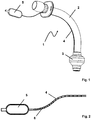
- the ventilation device 1 is a tracheostomy cannula with a cannula tube 2 and a cuff 3 which is tightly connected to the outside of the cannula tube 2.
- the cuff 3 is connected in fluid communication to a control balloon 5 via a filling tube 4.
- the cuff 3 can be filled with a gas or the cuff pressure can be regulated via the filling hose 4 and the control balloon 5.
- the inside of the filling hose 4 contains at least one surface-active substance 6 for reducing the surface tension of water.
- the at least one surface-active substance 6 was introduced into the filling tube 4 in the form of a soluble powder during the manufacture of the ventilation device 1.
- the at least one surface-active substance in this embodiment is in an amount of e.g. B. 0.01 g to 0.1 g before.
Landscapes
- Health & Medical Sciences (AREA)
- Pulmonology (AREA)
- Heart & Thoracic Surgery (AREA)
- Engineering & Computer Science (AREA)
- Anesthesiology (AREA)
- Biomedical Technology (AREA)
- Emergency Medicine (AREA)
- Hematology (AREA)
- Life Sciences & Earth Sciences (AREA)
- Animal Behavior & Ethology (AREA)
- General Health & Medical Sciences (AREA)
- Public Health (AREA)
- Veterinary Medicine (AREA)
- Respiratory Apparatuses And Protective Means (AREA)
- Materials For Medical Uses (AREA)
Abstract
Description
- Die vorliegende Erfindung betrifft eine Beatmungsvorrichtung, insbesondere einen Endotrachealtubus oder eine Tracheostomiekanüle, mit einem Kanülenrohr und einem dicht mit der Außenseite des Kanülenrohrs verbundenen Cuff, welcher über einen Füllschlauch mit einem Kontrollballon in Fluidverbindung steht oder in Verbindung gebracht werden kann.
- Beatmungsvorrichtungen werden in die Trachea eines Patienten eingeführt, um den Patienten mit Luft bzw. Atemgas zu versorgen. Das Kanülenrohr kann durch eine im Hals eines Patienten unterhalb des Kehlkopfbereichs künstlich erzeugte Öffnung (Tracheostoma) oder über den Mund und Rachenraum in die Trachea eines Patienten eingebracht werden. Das Kanülenrohr dient mit seinem zentralen Lumen der Hindurchleitung von Luft bzw. Atemgas.
- Der befüllbare Cuff auf dem äußeren Umfang des Kanülenrohrs dient der Abdichtung der Trachea in dem Volumen außerhalb des Kanülenrohrs. Ein solcher Cuff besteht üblicherweise aus einem aufblasbaren, flexiblen Schlauchabschnitt mit einer sehr geringen Wandstärke, dessen Endabschnitte außen auf dem Kanülenrohr anliegen und dort abgedichtet fixiert sind. Der Cuff hat mindestens in einem Abschnitt zwischen seinen Enden gegenüber dem Kanülenrohr ein deutliches Übermaß oder ist auf ein solches Übermaß aufblasbar. Beim Einführen des Kanülenrohrs in die Trachea liegt der zunächst ungefüllte Cuff eng an der Außenseite des Kanülenrohrs an und wird nach dem Einführen mit geringem Druck aufgeblasen, bis er mit der Wand der Trachea entlang seines Umfangs abdichtend, jedoch mit möglichst geringem Druck in Kontakt kommt.
- Der geringe Druck soll verhindern, dass der Cuff mit einem Anpressdruck an der Wand der Trachea anliegt, der die Durchblutung der Trachealwand unterbrechen kann und bei längerer Dauer der Anlage die Trachealwand nachhaltig beschädigen könnte. Der Anpressdruck an der Trachealwand ist von dem Druck im Cuff zu unterscheiden, der unter Umständen auch den Cuff elastisch dehnen muss. Der minimale Druck im Cuff, ab dem eine ausreichende Abdichtung gegenüber der Trachea erreicht wird, hängt daher unter anderem von der Dicke und Flexibilität der Cufffolie ab.
- Um eine bessere Kontrolle über den Anpressdruck des Cuffs an der Trachealwand zu haben, werden häufig sogenannte "High Volume Low Pressure Cuffs" (HVLP), verwendet, die von vornherein ein Übermaß aufweisen, so dass ihr maximales Volumen im nahezu drucklos aufgeblasenen Zustand das in der Trachea einzunehmende Volumen deutlich übersteigt.
- Auf diese Weise muss sich das Material des Cuffs bei der vorgesehenen Verwendung nicht ausdehnen, sondern muss sich lediglich aus einem an dem Kanülenrohr eng anliegenden Zustand entfalten und an die Trachealwand an anschmiegen. Wegen des Übermaßes hat der Cuff aber auch in seinem an der Trachealwand anliegenden Zustand noch immer Falten. Damit der Cuff trotz solcher Falten eine ausreichende Abdichtung gegenüber der Trachea erreicht, sollte der Druck in einem "High Volume Low Pressure Cuff" etwa 15 hPa bis 30 hPa betragen. Dies ist dann auch der Druck, mit welchem der Cuff an der Wand der Trachea anliegt und den es einzuhalten und zu kontrollieren gilt. Solche Cuffs sind vorzugsweise sehr dünnwandig, um den Faltenquerschnitt soweit wie möglich zu reduzieren und um so zu vermeiden, dass Flüssigkeiten oder Sekrete entlang der Falten den Cuff passieren können und Komplikationen verursachen.
- Zur Vermeidung von Trachealschäden einerseits und zur Erzielung einer ausreichenden Abdichtung andererseits ist es daher erforderlich, den Cuffdruck exakt einzustellen und regelmäßig zu überprüfen. Das gilt sowohl für "High Volume Low Pressure Cuffs" als auch für alle übrigen Arten von Cuffs, bei welchen der Druck, der im Cuff bzw. in einem mit dem Cuff in Fluidverbindung stehenden Volumen gemessen wird, um den zur Ausdehnung des Cuffs gegebenenfalls erforderlichen elastischen Anteil zu korrigieren ist. Dies hat allerdings den Nachteil, dass der so ermittelte Druckwert fehlerhaft ist, insbesondere wenn die elastische Rückstellkraft des Cuffmaterials im Laufe der Zeit nachlässt.
- "High Volume Low Pressure Cuffs" haben dagegen den Vorteil, dass der im Cuff gemessene Druck nahezu exakt dem Druck entspricht, mit dem der Cuff auf die Trachealwand drückt.
- Zum Einstellen und Überprüfen des Cuffsdrucks wird ein entsprechend konfektioniertes Manometer an einen Kontrollballon oder den Füllschlauch angeschlossen.
- Allerdings kann sich unter Umständen in dem Cuff und/oder in dem Füllschlauch und/oder in dem Kontrollballon Kondenswasser ansammeln. Wassermoleküle können beispielsweise durch die dünne Cuffwand in das Innere des Cuffs diffundieren und aufgrund von Temperaturschwankungen kondensieren. Bei der Kontrolle oder Einstellung des Cuffdrucks kann das Kondenswasser auch in den Füllschlauch und/oder in den Kontrollballon gelangen.
- Insbesondere in dem Füllschlauch befindliches Wasser kann zu Artefakten bei der Einstellung und Messung des Cuffdrucks führen. Wegen des geringen Querschnitts eines Füllschlauches und der im Vergleich zu Gasen relativ großen Viskosität und Benetzungsfähigkeit von Wasser wird das Wasser bei geringen Druckdifferenzen nicht durch den Füllschlauch hindurch gedrückt, sondern bildet eine Barriere in dem Füllschlauch und verfälscht so die Messung des Cuffdrucks. Eine Verfälschung des Messergebnisses ist insbesondere zu beobachten, wenn eine Wasserssäule in dem Füllschlauch durch Lufteinschlüsse unterbrochen ist.
- Die Ansammlung von Wasser durch Eindiffundieren und damit auch die Entstehung von entsprechenden Artefakten könnte durch die Verwendung von Cufffolien mit größeren Wandstärken verhindert werden, da die Barriereeigenschaften gegen Wasser mit der Wandstärke ansteigen. Dem steht aber die Faltenbildung und die dadurch bedingte Beeinträchtigung einer sicheren Abdichtung bei geringen Cuffdrücken entgegen.
- Aus der
WO 2006/089961 A1 ist ein Cuff mit einer Beschichtung bekannt, die verhindern soll, dass Luftfeuchtigkeit in den Cuff eindringt. Allerdings schmiegen sich Cufffolien mit größeren Wandstärken und Beschichtung schlechter an die Trachealwand an und dichten daher die Trachea bei gegebenen Anpressdruck weniger effektiv ab (siehe z.B.EP 1 061 984 B2 ). Alternativ könnten für den Cuff selbst Materialen verwendet werden, die ein Eindiffundieren von Luftfeuchtigkeit in den Cuff erschweren. Gute Barriereeigenschaften gegenüber Luftfeuchtigkeit haben beispielsweise Polypropylen, Polyethylen oder Teflon. Diese lassen sich jedoch bei der Herstellung nicht sonderlich gut mit einem Kanülenrohr verkleben, sodass in der Praxis Folien aus Polyvinylchlorid oder Polyurethan ungeachtet der geringen Barriereeigenschaften gegenüber Wasser bevorzugt sind. - Demgegenüber besteht eine Aufgabe der vorliegenden Erfindung darin, eine Beatmungsvorrichtung zu schaffen, die einerseits einen flexiblen und sich gut an die Trachealwand anlegenden Cuff aufweist, gleichzeitig aber wasserbedingte Artefakte bei der Messung und Einstellung eines Cuffdrucks einer Beatmungsvorrichtung vermeidet oder zumindest reduziert.
- Erfindungsgemäß wird diese Aufgabe durch eine Beatmungsvorrichtung der eingangs genannten Art gelöst, bei welcher das Innere des Cuffs und/oder des Füllschlauchs und/oder des Kontrollballons mindestens eine oberflächenaktive Substanz zur Herabsetzung der Oberflächenspannung von Wasser enthält.
- Die oberflächenaktive Substanz reduziert bei Kontakt mit Wasser dessen Oberflächenspannung und bewirkt so, dass das Wasser mit geringerer Reibung und Haftung an der Wand des Füllschlauches leichter und bei geringen Druckunterschieden durch den Füllschlauch bewegt werden kann. Das Wasser mit herabgesetzter Oberflächenspannung bildet somit keine bzw. nur geringfügige Barrieren, die eine Messung und Einstellung des Cuffdrucks verfälschen könnten.
- Die oberflächenaktiven Substanzen zur Herabsetzung der Oberflächenspannung von Wasser ermöglichen, den Innendurchmesser des Füllschlauchs gegenüber herkömmlichen Füllschläuchen deutlich zu reduzieren, ohne das der verringerte Innendurchmesser wasserbedingte Artefakte bei der Messung und Einstellung eines Cuffdrucks erzeugt. In einer Ausführungsform ist der Innendurchmesser des Füllschlauchs kleiner oder gleich 0,7 mm, vorzugsweise kleiner oder gleich 0,6 mm. Der Innendurchmesser des Füllschlauchs kann kleiner oder gleich 0,5 mm sein. Vorzugsweise ist der Innendurchmesser des Füllschlauchs größer oder gleich 0,3 mm.
- Da der Füllschlauch meist in die Wand des Kanülenrohrs eingelassen oder außenliegend auf der Wand des Kanülenrohrs angeordnet ist, kann die Wand des Kanülenrohrs bei der Verwendung eines Füllschlauchs mit einem kleinen Innendurchmesser dünner ausgeführt werden. Der Innendurchmesser des Kanülenrohrs kann um den durch die Verwendung eines Füllschlauchs mit kleinem Innendurchmesser eingesparten Platzbedarf vergrößert werden. Ein Kanülenrohr mit einem vergrößerten Innendurchmesser erzeugt einen geringeren Atemwiderstand als ein Kanülenrohr mit einem im Vergleich kleineren Innendurchmesser. Die Verwendung von Tensiden und einem Füllschlauch mit einem Innendurchmesser von kleiner oder gleich 0,7 mm ermöglicht es, eine Beatmungsvorrichtung mit einem reduzierten Atemwiderstand bereitzustellen.
- In einer Ausführungsform ist die oberflächenaktive Substanz zur Herabsetzung der Oberflächenspannung von Wasser in einer Menge von mindestens 0,01 g und/oder nicht mehr als 0,3 g, vorzugsweise nicht mehr als 0,1 g, vorhanden.
- Die oberflächenaktive Substanz zur Herabsetzung der Oberflächenspannung von Wasser kann mindestens ein wasserlösliches Tensid enthalten oder aus einem wasserlöslichen Tensid oder aus mehreren wasserlöslichen Tensiden bestehen. Das mindestens eine wasserlösliche Tensid oder die mehreren wasserlöslichen Tenside sind vorzugsweise ausgewählt aus der Gruppe umfassend: lineare Alkylbenzosulfonate (LAS), Alkylpolygglycoside (APG), Esterquats (EQ), Fettalkoholethoxylate (FAEO), Fettalkoholsulfate (FAS), Fettalkoholethersulfate (FES), Tyloxapol, Polysorbat 80, Natrium- oder Kaliumsalze von Fettsäuren, Emulgatoren, Natrium-, Kalium-, und CalciumSalze von Speisefettsäuren (E 470a), Mono- und Diglyceride von Speseefettsäuren (E 471), Polyoxyethylensorbitanmonolaurat (E 432), Polyoxyethylensorbitanmonooleat (E 433), Polyoxyethylensorbitanmonopalmitat (E 434), Polyoxyethenlyensorbitanmomostearat (E 435), Polyoxyethylen20-Sorbitantri-Stearat (E 436) und Propylenglycolalginat (E 405).
- Die oberflächenaktive Substanz kann zweckmäßigerweise dort in die Beatmungsvorrichtung eingebracht werden, wo sie mit dem Kondenswasser in Kontakt kommen kann. Beispielsweise kann die oberflächenaktive Substanz in das Innere des Cuffs und/oder in das Innere des Füllschlauchs und/oder in das Innere des Kontrollballons eingebracht werden. Grundsätzlich ist es ausreichend, wenn die mindestens eine oberflächenaktive Substanz an einer Stelle der Beatmungsvorrichtung vorhanden ist. Sobald die oberflächenaktive Substanz mit Wasser in Verbindung kommt, so löst und verteilt sich diese mindestens eine oberflächenaktive Substanz in dem Wasser.
- In einer Ausführungsform liegt die mindestens eine oberflächenaktive Substanz als eine Lösung, eine wässrige Lösung, als Schaum oder als ein löslicher Feststoff fließfähig vor.
- Durch Ihre Fließfähigkeit ist die mindestens eine oberflächenaktive Substanz selbst bewegbar und damit erhöht sich die Wahrscheinlichkeit, dass die mindestens eine oberflächenaktive Substanz mit dem Wasser in dem Cuff der Beatmungsvorrichtung in Kontakt kommt.
- Eine Lösung, eine wässrige Lösung, ein Schaum oder ein löslicher Feststoff, beispielsweise in Form eines Pulvers, kann durch die Luft in dem Füllschlauch, dem Kontrollballon oder dem Cuff verwirbelt und verteilt werden. Die mindestens eine oberflächenaktive Substanz kann auch in Form einer löslichen Beschichtung die Innenfläche des Cuffs und/oder die Innenfläche des Füllschlauchs und/oder die Innenfläche des Kontrollballons teilweise oder ganz auskleiden.
- Die erfindungsgemäße Aufgabe wird auch durch ein Verfahren zur Erleichterung eines Wassertransports durch einen Füllschlauch einer Beatmungsvorrichtung, insbesondere Endotrachealtubus oder Tracheostomiekanüle, gelöst, wobei die Beatmungsvorrichtung ein Kanülenrohr und ein dicht mit der Außenseite des Kanülenrohrs verbundenen Cuff aufweist, der über den Füllschlauch mit einem Kontrollballon in fluider Kommunikation verbunden ist, wobei das Verfahren den Schritt aufweist:
Einbringen mindestens einer oberflächenaktiven Substanz zur Herabsetzung der Oberflächenspannung von Wasser in das Innere des Cuffs und/oder des Füllschlauchs und/oder des Kontrollballons. - Die mindestens eine oberflächenaktive Substanz kann bei der Herstellung der Beatmungsvorrichtung oder nach der Herstellung der Beatmungsvorrichtung eingebracht werden. Beispielsweise kann die oberflächenaktive Substanz als wässrige Lösung in den Kontrollballon und/oder den Cuff und/oder den Füllschlauch und/oder über ein am Kontrollballon befindliches Füllventil injiziert werden. Aufgrund der geringen Barriereeigenschaft des Cuffs gegenüber Wasser verdunstet das Waser und die oberflächenaktive Substanz bleibt feinverteilt im Inneren des Kontrollballons und/oder des Füllschlauchs und/oder des Cuffs zurück. Im Unterschied zu Waser können die oberflächenaktiven Substanzen aufgrund ihrer deutlich erhöhten Molekülgröße nicht durch die Wand des Cuffs nach Außen diffundieren.
- Weitere Vorteile, Merkmale und Anwendungsmöglichkeiten der vorliegenden Erfindung werden anhand der folgenden Beschreibung einer Ausführungsform und den dazugehörigen Figuren deutlich, wobei gleiche Bezugszeichen auf gleiche Elemente verweisen. Es zeigen:
- Figur 1:
- eine Beatmungsvorrichtung gemäß einer Ausführungsform der vorliegenden Erfindung, und
- Figur 2:
- einen vergrößerten Längsschnitt durch den Füllschlauchs aus
Figur 1 . - In der
Figur 1 ist eine Beatmungsvorrichtung gemäß einer Ausführungsform der vorliegenden Erfindung gezeigt. Die Beatmungsvorrichtung 1 ist eine Tracheostomiekanüle mit einem Kanülenrohr 2 und einem dicht mit der Außenseite des Kanülenrohrs 2 verbundenen Cuffs 3. Der Cuff 3 ist in fluider Kommunikation über einen Füllschlauch 4 mit einem Kontrollballon 5 verbunden. Über den Füllschlauch 4 und den Kontrollballon 5 kann der Cuff 3 mit einem Gas befüllt bzw. der Cuffdruck reguliert werden. - Wie in der
Figur 2 , die einen vergrößerten Längsschnitt durch den Füllschlauch 4 und den Kontrollballon 5 zeigt, angedeutet, enthält das innere des Füllschlauchs 4 mindestens eine oberflächenaktive Substanz 6 zur Herabsetzung der Oberflächenspannung von Wasser. Die mindestens eine oberflächenaktive Substanz 6 wurde in Form eines löslichen Pulvers bei der Herstellung der Beatmungsvorrichtung 1 in den Füllschlauch 4 eingebracht. Die mindestens eine oberflächenaktive Substanz liegt bei dieser Ausführungsform in einer Menge von z. B. 0,01 g bis 0,1 g vor. - Für Zwecke der ursprünglichen Offenbarung wird darauf hingewiesen, dass sämtliche Merkmale, wie sie sich aus der vorliegenden Beschreibung, den Zeichnungen und den Ansprüchen für einen Fachmann erschließen, auch wenn sie konkret nur im Zusammenhang mit bestimmten weiteren Merkmalen beschrieben wurden, sowohl einzeln als auch in beliebigen Zusammenstellungen mit anderen der hier offenbarten Merkmale oder Merkmalsgruppen kombinierbar sind, soweit dies nicht ausdrücklich ausgeschlossen wurde oder technische Gegebenheiten derartige Kombinationen unmöglich oder sinnlos machen. Auf die umfassende, explizite Darstellung sämtlicher denkbarerer Merkmalskombinationen wird hier nur der Kürze und der Lesbarkeit der Beschreibung wegen verzichtet.
- Während die Erfindung im Detail in den Zeichnungen und der vorangehenden Beschreibung dargestellt und beschreiben wurde, erfolgt diese Darstellung und Beschreibung lediglich beispielhaft und ist nicht als Beschränkung des Schutzbereichs gedacht, so wie er durch die Ansprüche definiert wird. Die Erfindung ist nicht auf die offenbarten Ausführungsformen beschränkt.
- Abwandlungen der offenbarten Ausführungsformen sind für den Fachmann aus den Zeichnungen, der Beschreibung und den beigefügten Ansprüchen offensichtlich. In den Ansprüchen schließt das Wort "aufweisen" nicht andere Elemente oder Schritte aus, und der unbestimmte Artikel "eine" oder "ein" schließt eine Mehrzahl nicht aus. Die bloße Tatsache, dass bestimmte Merkmale in unterschiedlichen Ansprüchen beansprucht sind, schließt ihre Kombination nicht aus. Bezugszeichen in den Ansprüchen sind nicht als Beschränkung des Schutzbereichs gedacht.
-
- 1
- Beatmungsvorrichtung
- 2
- Kanülenrohr
- 3
- Cuff
- 4
- Füllschlauch
- 5
- Kontrollballon
- 6
- oberflächenaktive Substanz
Claims (10)
- Beatmungsvorrichtung (1), insbesondere Endotrachealtubus oder Tracheostomiekanüle, mit einem Kanülenrohr (2) und einem dicht mit der Außenseite des Kanülenrohrs (2) verbundenen Cuff (3), welcher über einen Füllschlauch (4) mit einem Kontrollballon (5) in Fluidverbindung steht oder in Fluidverbindung gebracht werden kann.
dadurch gekennzeichnet, dass
das Innere des Cuffs (3) und/oder das Innere des Füllschlauchs (4) und/oder das Innere des Kontrollballons (5) mindestens eine oberflächenaktive Substanz (6) zur Herabsetzung der Oberflächenspannung von Wasser enthält. - Beatmungsvorrichtung (1) nach Anspruch 1, dadurch gekennzeichnet, dass die oberflächenaktive Substanz (6) zur Herabsetzung der Oberflächenspannung von Wasser in einer Menge von mindestens 0,01 g und/oder nicht mehr als 0,3 g, vorzugsweise nicht mehr als 0,1 g, vorhanden ist.
- Beatmungsvorrichtung (1) nach Anspruch 1 oder 2, dadurch gekennzeichnet, dass die oberflächenaktive Substanz (6) zur Herabsetzung der Oberflächenspannung von Wasser mindestens ein Tensid enthält oder aus einem Tensid oder mehreren Tensiden besteht.
- Beatmungsvorrichtung (1) nach einem der Ansprüche 1 bis 3, dadurch gekennzeichnet, dass die mindestens eine oberflächenaktive Substanz (6) in Form einer Lösung, einer wässrigen Lösung, eines Schaums oder eines löslichen Feststoffs vorliegt.
- Beatmungsvorrichtung (1) nach einem der Ansprüche 1 bis 4, dadurch gekennzeichnet, dass der Füllschlauch einen Innendurchmesser von kleiner 0,7 mm, vorzugsweise kleiner oder gleich 0,6 mm, wobei vorzugsweise der Innendurchmesser größer oder gleich 0,3 mm ist.
- Verfahren zur Verringerung des Durchflusswiderstandes von Wasser in einem Füllschlauch (4) einer Beatmungsvorrichtung (1), insbesondere Endotrachealtubus oder Tracheostomiekanüle, wobei die Beatmungsvorrichtung (1) ein Kanülenrohr (2) und ein dicht mit der Außenseite des Kanülenrohrs (2) verbundenen Cuff (3) aufweist, der über den Füllschlauch (4) mit einem Kontrollballon (5) in Fluidverbindung steht oder bringbar ist, gekennzeichnet durcha) Einbringen mindestens einer oberflächenaktiven Substanz (6) zur Herabsetzung der Oberflächenspannung von Wasser in das Innere des Cuffs (3) und/oder in das Innere des Füllschlauchs (4) und/oder des Kontrollballons (5).
- Verfahren nach Anspruch 6, dadurch gekennzeichnet, dass der Schritt a) bei der Herstellung der Beatmungsvorrichtung (1) oder nach der Herstellung der Beatmungsvorrichtung (1) ausgeführt wird.
- Verfahren nach Anspruch 6 oder 7, dadurch gekennzeichnet, dass die Menge der mindestens einen oberflächenaktiv Substanz (6) zur Herabsetzung der Oberflächenspannung von Wasser in einer fließfähigen Form als Lösung, insbesondere als wässrige Lösung, als Schaum oder als lösliches Pulver eingebracht wird.
- Verfahren nach einem der Ansprüche 6 bis 8, gekennzeichnet durch b) Injizieren der mindestens einen oberflächenaktiven Substanz (6) zur Herabsetzung der Oberflächenspannung von Wasser in Form einer wässrigen Lösung in den Cuff (3) und/oder in den Kontrollballon (4) und/oder in den Füllschlauch (5), und c) Verdunsten des Wasseranteils derwässrigen Lösung.
- Verfahren nach einem der Ansprüche 6 bis 9, dadurch gekennzeichnet, dass die oberflächenaktive Substanz (6) zur Herabsetzung der Oberflächenspannung von Wasser in einer Menge von mindestens 0,01 g und/oder nicht mehr als 0,3 g, vorzugsweise nicht mehr als 0,1 g, eingebracht wird.
Applications Claiming Priority (1)
| Application Number | Priority Date | Filing Date | Title |
|---|---|---|---|
| DE102018121001.9A DE102018121001A1 (de) | 2018-08-28 | 2018-08-28 | Beatmungsvorrichtung |
Publications (3)
| Publication Number | Publication Date |
|---|---|
| EP3620196A1 true EP3620196A1 (de) | 2020-03-11 |
| EP3620196B1 EP3620196B1 (de) | 2023-06-07 |
| EP3620196B8 EP3620196B8 (de) | 2023-07-12 |
Family
ID=67659232
Family Applications (1)
| Application Number | Title | Priority Date | Filing Date |
|---|---|---|---|
| EP19192229.3A Active EP3620196B8 (de) | 2018-08-28 | 2019-08-19 | Beatmungsvorrichtung |
Country Status (2)
| Country | Link |
|---|---|
| EP (1) | EP3620196B8 (de) |
| DE (1) | DE102018121001A1 (de) |
Citations (3)
| Publication number | Priority date | Publication date | Assignee | Title |
|---|---|---|---|---|
| WO2006089961A1 (de) | 2005-02-28 | 2006-08-31 | Tracoe Medical Gmbh | Vorrichtung zur atemluftzuführung |
| DE102005015045A1 (de) * | 2005-03-31 | 2006-10-05 | Tracoe Medical Gmbh | Beschichtete Manschette |
| EP1061984B2 (de) | 1998-03-09 | 2010-03-03 | Kimberly-Clark Worldwide, Inc. | Trachealbeatmungsvorrichtung |
Family Cites Families (2)
| Publication number | Priority date | Publication date | Assignee | Title |
|---|---|---|---|---|
| DE19855521A1 (de) * | 1998-12-02 | 2000-06-08 | Tracoe Medizine Ges Fuer | Tubus mit abgedichteter Manschette |
| US20080078406A1 (en) * | 2006-09-29 | 2008-04-03 | Jessica Clayton | Endotracheal tube and technique for using the same |
-
2018
- 2018-08-28 DE DE102018121001.9A patent/DE102018121001A1/de not_active Withdrawn
-
2019
- 2019-08-19 EP EP19192229.3A patent/EP3620196B8/de active Active
Patent Citations (3)
| Publication number | Priority date | Publication date | Assignee | Title |
|---|---|---|---|---|
| EP1061984B2 (de) | 1998-03-09 | 2010-03-03 | Kimberly-Clark Worldwide, Inc. | Trachealbeatmungsvorrichtung |
| WO2006089961A1 (de) | 2005-02-28 | 2006-08-31 | Tracoe Medical Gmbh | Vorrichtung zur atemluftzuführung |
| DE102005015045A1 (de) * | 2005-03-31 | 2006-10-05 | Tracoe Medical Gmbh | Beschichtete Manschette |
Non-Patent Citations (1)
| Title |
|---|
| MATSUBA KOHEI ET AL: "Cuff leakage caused by automatic cuff pressure monitor and water condensation in the inflation tube of Microcuff endotracheal tube.", ANAESTHESIA AND INTENSIVE CARE MAY 2019, vol. 47, no. 3, May 2019 (2019-05-01), pages 300 - 301, XP009518191, ISSN: 0310-057X * |
Also Published As
| Publication number | Publication date |
|---|---|
| DE102018121001A1 (de) | 2020-03-05 |
| EP3620196B1 (de) | 2023-06-07 |
| EP3620196B8 (de) | 2023-07-12 |
Similar Documents
| Publication | Publication Date | Title |
|---|---|---|
| DE19855521A1 (de) | Tubus mit abgedichteter Manschette | |
| EP2068989B1 (de) | Manschette einer beatmungsvorrichtung | |
| DE2827648A1 (de) | Pneumatisch geregeltes druckentlastungsventil, insbesondere fuer medizinische anwendungen | |
| EP2931343B1 (de) | Druckausgleichsvorrichtung | |
| DE2212965A1 (de) | Aufblasbare Manschette | |
| EP4271454B1 (de) | Beatmungsvorrichtung mit stoma-manschette | |
| DE2659440A1 (de) | Ventil | |
| WO1998010819A1 (de) | Trachealtubus | |
| EP4271453B1 (de) | Beatmungsvorrichtung mit sprechluft-zuführung | |
| EP2931345B1 (de) | Druckausgleichsballon und verfahren zu dessen herstellung | |
| EP1861152B1 (de) | Vorrichtung zur atemluftzuführung | |
| DE60107704T2 (de) | Befestigungsvorrichtung für schlauchelemente | |
| DE3028568C2 (de) | Endotrachealtubus | |
| EP3620196B1 (de) | Beatmungsvorrichtung | |
| DE19962372A1 (de) | Transpharyngealtubus | |
| DE3921524A1 (de) | Trachealtubus mit permeationsstabiler blockungsmanschette | |
| EP4114487B1 (de) | Trachealbeatmungsvorrichtung mit optimiertem cuff-schlauch | |
| WO2007085625A1 (de) | Vorrichtung zur einstellung und kontrolle des druckes in manschetten von endotracheal- oder tracheostomiekanülen | |
| EP4176914B1 (de) | Beatmungsvorrichtung mit leitung zum befüllen eines cuffs im trachealabschnitt | |
| EP3969089B1 (de) | Ballon mit einem mehrlagigen wandungsaufbau für die gewebeschonende niederdruck-dichtung von öffnungen und hohlräumen im körper eines patienten, insbesondere bei zyklisch schwankenden fülldruckwerten | |
| DE69806789T2 (de) | Dichtung für ein ventil | |
| DE2127589C3 (de) | Trachealtubus | |
| DE2400569A1 (de) | Trachealtubus mit abdichtmanschette | |
| DE102005015045A1 (de) | Beschichtete Manschette | |
| DE19730286A1 (de) | Trachealkanüle |
Legal Events
| Date | Code | Title | Description |
|---|---|---|---|
| PUAI | Public reference made under article 153(3) epc to a published international application that has entered the european phase |
Free format text: ORIGINAL CODE: 0009012 |
|
| STAA | Information on the status of an ep patent application or granted ep patent |
Free format text: STATUS: THE APPLICATION HAS BEEN PUBLISHED |
|
| AK | Designated contracting states |
Kind code of ref document: A1 Designated state(s): AL AT BE BG CH CY CZ DE DK EE ES FI FR GB GR HR HU IE IS IT LI LT LU LV MC MK MT NL NO PL PT RO RS SE SI SK SM TR |
|
| AX | Request for extension of the european patent |
Extension state: BA ME |
|
| STAA | Information on the status of an ep patent application or granted ep patent |
Free format text: STATUS: REQUEST FOR EXAMINATION WAS MADE |
|
| 17P | Request for examination filed |
Effective date: 20200716 |
|
| RBV | Designated contracting states (corrected) |
Designated state(s): AL AT BE BG CH CY CZ DE DK EE ES FI FR GB GR HR HU IE IS IT LI LT LU LV MC MK MT NL NO PL PT RO RS SE SI SK SM TR |
|
| GRAP | Despatch of communication of intention to grant a patent |
Free format text: ORIGINAL CODE: EPIDOSNIGR1 |
|
| STAA | Information on the status of an ep patent application or granted ep patent |
Free format text: STATUS: GRANT OF PATENT IS INTENDED |
|
| INTG | Intention to grant announced |
Effective date: 20221006 |
|
| GRAS | Grant fee paid |
Free format text: ORIGINAL CODE: EPIDOSNIGR3 |
|
| GRAA | (expected) grant |
Free format text: ORIGINAL CODE: 0009210 |
|
| STAA | Information on the status of an ep patent application or granted ep patent |
Free format text: STATUS: THE PATENT HAS BEEN GRANTED |
|
| AK | Designated contracting states |
Kind code of ref document: B1 Designated state(s): AL AT BE BG CH CY CZ DE DK EE ES FI FR GB GR HR HU IE IS IT LI LT LU LV MC MK MT NL NO PL PT RO RS SE SI SK SM TR |
|
| REG | Reference to a national code |
Ref country code: GB Ref legal event code: FG4D Free format text: NOT ENGLISH Ref country code: DE Ref legal event code: R081 Ref document number: 502019007909 Country of ref document: DE Owner name: COLOPLAST A/S, DK Free format text: FORMER OWNER: TRACOE MEDICAL GMBH, 55268 NIEDER-OLM, DE |
|
| REG | Reference to a national code |
Ref country code: CH Ref legal event code: PK Free format text: BERICHTIGUNG B8 Ref country code: CH Ref legal event code: EP Ref country code: AT Ref legal event code: REF Ref document number: 1573064 Country of ref document: AT Kind code of ref document: T Effective date: 20230615 Ref country code: DE Ref legal event code: R096 Ref document number: 502019007909 Country of ref document: DE |
|
| RAP2 | Party data changed (patent owner data changed or rights of a patent transferred) |
Owner name: COLOPLAST A/S |
|
| REG | Reference to a national code |
Ref country code: LT Ref legal event code: MG9D |
|
| REG | Reference to a national code |
Ref country code: NL Ref legal event code: MP Effective date: 20230607 |
|
| PG25 | Lapsed in a contracting state [announced via postgrant information from national office to epo] |
Ref country code: SE Free format text: LAPSE BECAUSE OF FAILURE TO SUBMIT A TRANSLATION OF THE DESCRIPTION OR TO PAY THE FEE WITHIN THE PRESCRIBED TIME-LIMIT Effective date: 20230607 Ref country code: NO Free format text: LAPSE BECAUSE OF FAILURE TO SUBMIT A TRANSLATION OF THE DESCRIPTION OR TO PAY THE FEE WITHIN THE PRESCRIBED TIME-LIMIT Effective date: 20230907 Ref country code: ES Free format text: LAPSE BECAUSE OF FAILURE TO SUBMIT A TRANSLATION OF THE DESCRIPTION OR TO PAY THE FEE WITHIN THE PRESCRIBED TIME-LIMIT Effective date: 20230607 |
|
| PG25 | Lapsed in a contracting state [announced via postgrant information from national office to epo] |
Ref country code: RS Free format text: LAPSE BECAUSE OF FAILURE TO SUBMIT A TRANSLATION OF THE DESCRIPTION OR TO PAY THE FEE WITHIN THE PRESCRIBED TIME-LIMIT Effective date: 20230607 Ref country code: NL Free format text: LAPSE BECAUSE OF FAILURE TO SUBMIT A TRANSLATION OF THE DESCRIPTION OR TO PAY THE FEE WITHIN THE PRESCRIBED TIME-LIMIT Effective date: 20230607 Ref country code: LV Free format text: LAPSE BECAUSE OF FAILURE TO SUBMIT A TRANSLATION OF THE DESCRIPTION OR TO PAY THE FEE WITHIN THE PRESCRIBED TIME-LIMIT Effective date: 20230607 Ref country code: LT Free format text: LAPSE BECAUSE OF FAILURE TO SUBMIT A TRANSLATION OF THE DESCRIPTION OR TO PAY THE FEE WITHIN THE PRESCRIBED TIME-LIMIT Effective date: 20230607 Ref country code: HR Free format text: LAPSE BECAUSE OF FAILURE TO SUBMIT A TRANSLATION OF THE DESCRIPTION OR TO PAY THE FEE WITHIN THE PRESCRIBED TIME-LIMIT Effective date: 20230607 Ref country code: GR Free format text: LAPSE BECAUSE OF FAILURE TO SUBMIT A TRANSLATION OF THE DESCRIPTION OR TO PAY THE FEE WITHIN THE PRESCRIBED TIME-LIMIT Effective date: 20230908 |
|
| PG25 | Lapsed in a contracting state [announced via postgrant information from national office to epo] |
Ref country code: FI Free format text: LAPSE BECAUSE OF FAILURE TO SUBMIT A TRANSLATION OF THE DESCRIPTION OR TO PAY THE FEE WITHIN THE PRESCRIBED TIME-LIMIT Effective date: 20230607 |
|
| REG | Reference to a national code |
Ref country code: GB Ref legal event code: 732E Free format text: REGISTERED BETWEEN 20231214 AND 20231220 |
|
| PG25 | Lapsed in a contracting state [announced via postgrant information from national office to epo] |
Ref country code: SK Free format text: LAPSE BECAUSE OF FAILURE TO SUBMIT A TRANSLATION OF THE DESCRIPTION OR TO PAY THE FEE WITHIN THE PRESCRIBED TIME-LIMIT Effective date: 20230607 |
|
| PG25 | Lapsed in a contracting state [announced via postgrant information from national office to epo] |
Ref country code: IS Free format text: LAPSE BECAUSE OF FAILURE TO SUBMIT A TRANSLATION OF THE DESCRIPTION OR TO PAY THE FEE WITHIN THE PRESCRIBED TIME-LIMIT Effective date: 20231007 |
|
| PG25 | Lapsed in a contracting state [announced via postgrant information from national office to epo] |
Ref country code: SM Free format text: LAPSE BECAUSE OF FAILURE TO SUBMIT A TRANSLATION OF THE DESCRIPTION OR TO PAY THE FEE WITHIN THE PRESCRIBED TIME-LIMIT Effective date: 20230607 Ref country code: SK Free format text: LAPSE BECAUSE OF FAILURE TO SUBMIT A TRANSLATION OF THE DESCRIPTION OR TO PAY THE FEE WITHIN THE PRESCRIBED TIME-LIMIT Effective date: 20230607 Ref country code: RO Free format text: LAPSE BECAUSE OF FAILURE TO SUBMIT A TRANSLATION OF THE DESCRIPTION OR TO PAY THE FEE WITHIN THE PRESCRIBED TIME-LIMIT Effective date: 20230607 Ref country code: PT Free format text: LAPSE BECAUSE OF FAILURE TO SUBMIT A TRANSLATION OF THE DESCRIPTION OR TO PAY THE FEE WITHIN THE PRESCRIBED TIME-LIMIT Effective date: 20231009 Ref country code: IS Free format text: LAPSE BECAUSE OF FAILURE TO SUBMIT A TRANSLATION OF THE DESCRIPTION OR TO PAY THE FEE WITHIN THE PRESCRIBED TIME-LIMIT Effective date: 20231007 Ref country code: EE Free format text: LAPSE BECAUSE OF FAILURE TO SUBMIT A TRANSLATION OF THE DESCRIPTION OR TO PAY THE FEE WITHIN THE PRESCRIBED TIME-LIMIT Effective date: 20230607 Ref country code: CZ Free format text: LAPSE BECAUSE OF FAILURE TO SUBMIT A TRANSLATION OF THE DESCRIPTION OR TO PAY THE FEE WITHIN THE PRESCRIBED TIME-LIMIT Effective date: 20230607 |
|
| PG25 | Lapsed in a contracting state [announced via postgrant information from national office to epo] |
Ref country code: PL Free format text: LAPSE BECAUSE OF FAILURE TO SUBMIT A TRANSLATION OF THE DESCRIPTION OR TO PAY THE FEE WITHIN THE PRESCRIBED TIME-LIMIT Effective date: 20230607 |
|
| REG | Reference to a national code |
Ref country code: DE Ref legal event code: R097 Ref document number: 502019007909 Country of ref document: DE |
|
| PG25 | Lapsed in a contracting state [announced via postgrant information from national office to epo] |
Ref country code: MC Free format text: LAPSE BECAUSE OF FAILURE TO SUBMIT A TRANSLATION OF THE DESCRIPTION OR TO PAY THE FEE WITHIN THE PRESCRIBED TIME-LIMIT Effective date: 20230607 |
|
| REG | Reference to a national code |
Ref country code: CH Ref legal event code: PL |
|
| PG25 | Lapsed in a contracting state [announced via postgrant information from national office to epo] |
Ref country code: MC Free format text: LAPSE BECAUSE OF FAILURE TO SUBMIT A TRANSLATION OF THE DESCRIPTION OR TO PAY THE FEE WITHIN THE PRESCRIBED TIME-LIMIT Effective date: 20230607 |
|
| PLBE | No opposition filed within time limit |
Free format text: ORIGINAL CODE: 0009261 |
|
| STAA | Information on the status of an ep patent application or granted ep patent |
Free format text: STATUS: NO OPPOSITION FILED WITHIN TIME LIMIT |
|
| PG25 | Lapsed in a contracting state [announced via postgrant information from national office to epo] |
Ref country code: LU Free format text: LAPSE BECAUSE OF NON-PAYMENT OF DUE FEES Effective date: 20230819 |
|
| PG25 | Lapsed in a contracting state [announced via postgrant information from national office to epo] |
Ref country code: LU Free format text: LAPSE BECAUSE OF NON-PAYMENT OF DUE FEES Effective date: 20230819 Ref country code: DK Free format text: LAPSE BECAUSE OF FAILURE TO SUBMIT A TRANSLATION OF THE DESCRIPTION OR TO PAY THE FEE WITHIN THE PRESCRIBED TIME-LIMIT Effective date: 20230607 Ref country code: CH Free format text: LAPSE BECAUSE OF NON-PAYMENT OF DUE FEES Effective date: 20230831 |
|
| PG25 | Lapsed in a contracting state [announced via postgrant information from national office to epo] |
Ref country code: SI Free format text: LAPSE BECAUSE OF FAILURE TO SUBMIT A TRANSLATION OF THE DESCRIPTION OR TO PAY THE FEE WITHIN THE PRESCRIBED TIME-LIMIT Effective date: 20230607 |
|
| REG | Reference to a national code |
Ref country code: BE Ref legal event code: MM Effective date: 20230831 |
|
| 26N | No opposition filed |
Effective date: 20240308 |
|
| REG | Reference to a national code |
Ref country code: IE Ref legal event code: MM4A |
|
| PG25 | Lapsed in a contracting state [announced via postgrant information from national office to epo] |
Ref country code: SI Free format text: LAPSE BECAUSE OF FAILURE TO SUBMIT A TRANSLATION OF THE DESCRIPTION OR TO PAY THE FEE WITHIN THE PRESCRIBED TIME-LIMIT Effective date: 20230607 Ref country code: IT Free format text: LAPSE BECAUSE OF FAILURE TO SUBMIT A TRANSLATION OF THE DESCRIPTION OR TO PAY THE FEE WITHIN THE PRESCRIBED TIME-LIMIT Effective date: 20230607 |
|
| PG25 | Lapsed in a contracting state [announced via postgrant information from national office to epo] |
Ref country code: IE Free format text: LAPSE BECAUSE OF NON-PAYMENT OF DUE FEES Effective date: 20230819 |
|
| PG25 | Lapsed in a contracting state [announced via postgrant information from national office to epo] |
Ref country code: IE Free format text: LAPSE BECAUSE OF NON-PAYMENT OF DUE FEES Effective date: 20230819 |
|
| PG25 | Lapsed in a contracting state [announced via postgrant information from national office to epo] |
Ref country code: BE Free format text: LAPSE BECAUSE OF NON-PAYMENT OF DUE FEES Effective date: 20230831 |
|
| PG25 | Lapsed in a contracting state [announced via postgrant information from national office to epo] |
Ref country code: BG Free format text: LAPSE BECAUSE OF FAILURE TO SUBMIT A TRANSLATION OF THE DESCRIPTION OR TO PAY THE FEE WITHIN THE PRESCRIBED TIME-LIMIT Effective date: 20230607 |
|
| PG25 | Lapsed in a contracting state [announced via postgrant information from national office to epo] |
Ref country code: BG Free format text: LAPSE BECAUSE OF FAILURE TO SUBMIT A TRANSLATION OF THE DESCRIPTION OR TO PAY THE FEE WITHIN THE PRESCRIBED TIME-LIMIT Effective date: 20230607 |
|
| PG25 | Lapsed in a contracting state [announced via postgrant information from national office to epo] |
Ref country code: CY Free format text: LAPSE BECAUSE OF FAILURE TO SUBMIT A TRANSLATION OF THE DESCRIPTION OR TO PAY THE FEE WITHIN THE PRESCRIBED TIME-LIMIT; INVALID AB INITIO Effective date: 20190819 |
|
| PG25 | Lapsed in a contracting state [announced via postgrant information from national office to epo] |
Ref country code: HU Free format text: LAPSE BECAUSE OF FAILURE TO SUBMIT A TRANSLATION OF THE DESCRIPTION OR TO PAY THE FEE WITHIN THE PRESCRIBED TIME-LIMIT; INVALID AB INITIO Effective date: 20190819 |
|
| PGFP | Annual fee paid to national office [announced via postgrant information from national office to epo] |
Ref country code: DE Payment date: 20250827 Year of fee payment: 7 |
|
| REG | Reference to a national code |
Ref country code: AT Ref legal event code: MM01 Ref document number: 1573064 Country of ref document: AT Kind code of ref document: T Effective date: 20240819 |
|
| PGFP | Annual fee paid to national office [announced via postgrant information from national office to epo] |
Ref country code: GB Payment date: 20250827 Year of fee payment: 7 |
|
| PG25 | Lapsed in a contracting state [announced via postgrant information from national office to epo] |
Ref country code: AT Free format text: LAPSE BECAUSE OF NON-PAYMENT OF DUE FEES Effective date: 20240819 |
|
| PGFP | Annual fee paid to national office [announced via postgrant information from national office to epo] |
Ref country code: FR Payment date: 20250825 Year of fee payment: 7 |
|
| PG25 | Lapsed in a contracting state [announced via postgrant information from national office to epo] |
Ref country code: TR Free format text: LAPSE BECAUSE OF FAILURE TO SUBMIT A TRANSLATION OF THE DESCRIPTION OR TO PAY THE FEE WITHIN THE PRESCRIBED TIME-LIMIT Effective date: 20230607 |
|
| PGFP | Annual fee paid to national office [announced via postgrant information from national office to epo] |
Ref country code: AT Payment date: 20260410 Year of fee payment: 5 |