EP3620220B1 - Dispositif filtrant - Google Patents
Dispositif filtrant Download PDFInfo
- Publication number
- EP3620220B1 EP3620220B1 EP19193977.6A EP19193977A EP3620220B1 EP 3620220 B1 EP3620220 B1 EP 3620220B1 EP 19193977 A EP19193977 A EP 19193977A EP 3620220 B1 EP3620220 B1 EP 3620220B1
- Authority
- EP
- European Patent Office
- Prior art keywords
- filter
- fluid
- cap part
- element material
- casing
- Prior art date
- Legal status (The legal status is an assumption and is not a legal conclusion. Google has not performed a legal analysis and makes no representation as to the accuracy of the status listed.)
- Active
Links
Images
Classifications
-
- B—PERFORMING OPERATIONS; TRANSPORTING
- B01—PHYSICAL OR CHEMICAL PROCESSES OR APPARATUS IN GENERAL
- B01D—SEPARATION
- B01D29/00—Filters with filtering elements stationary during filtration, e.g. pressure or suction filters, not covered by groups B01D24/00 - B01D27/00; Filtering elements therefor
- B01D29/11—Filters with filtering elements stationary during filtration, e.g. pressure or suction filters, not covered by groups B01D24/00 - B01D27/00; Filtering elements therefor with bag, cage, hose, tube, sleeve or like filtering elements
- B01D29/13—Supported filter elements
- B01D29/15—Supported filter elements arranged for inward flow filtration
-
- B—PERFORMING OPERATIONS; TRANSPORTING
- B01—PHYSICAL OR CHEMICAL PROCESSES OR APPARATUS IN GENERAL
- B01D—SEPARATION
- B01D29/00—Filters with filtering elements stationary during filtration, e.g. pressure or suction filters, not covered by groups B01D24/00 - B01D27/00; Filtering elements therefor
- B01D29/88—Filters with filtering elements stationary during filtration, e.g. pressure or suction filters, not covered by groups B01D24/00 - B01D27/00; Filtering elements therefor having feed or discharge devices
- B01D29/90—Filters with filtering elements stationary during filtration, e.g. pressure or suction filters, not covered by groups B01D24/00 - B01D27/00; Filtering elements therefor having feed or discharge devices for feeding
- B01D29/902—Filters with filtering elements stationary during filtration, e.g. pressure or suction filters, not covered by groups B01D24/00 - B01D27/00; Filtering elements therefor having feed or discharge devices for feeding containing fixed liquid displacement elements or cores
-
- B—PERFORMING OPERATIONS; TRANSPORTING
- B01—PHYSICAL OR CHEMICAL PROCESSES OR APPARATUS IN GENERAL
- B01D—SEPARATION
- B01D35/00—Filtering devices having features not specifically covered by groups B01D24/00 - B01D33/00, or for applications not specifically covered by groups B01D24/00 - B01D33/00; Auxiliary devices for filtration; Filter housing constructions
- B01D35/30—Filter housing constructions
- B01D35/31—Filter housing constructions including arrangements for environmental protection, e.g. pressure resisting features
-
- F—MECHANICAL ENGINEERING; LIGHTING; HEATING; WEAPONS; BLASTING
- F01—MACHINES OR ENGINES IN GENERAL; ENGINE PLANTS IN GENERAL; STEAM ENGINES
- F01N—GAS-FLOW SILENCERS OR EXHAUST APPARATUS FOR MACHINES OR ENGINES IN GENERAL; GAS-FLOW SILENCERS OR EXHAUST APPARATUS FOR INTERNAL-COMBUSTION ENGINES
- F01N13/00—Exhaust or silencing apparatus characterised by constructional features
-
- F—MECHANICAL ENGINEERING; LIGHTING; HEATING; WEAPONS; BLASTING
- F01—MACHINES OR ENGINES IN GENERAL; ENGINE PLANTS IN GENERAL; STEAM ENGINES
- F01N—GAS-FLOW SILENCERS OR EXHAUST APPARATUS FOR MACHINES OR ENGINES IN GENERAL; GAS-FLOW SILENCERS OR EXHAUST APPARATUS FOR INTERNAL-COMBUSTION ENGINES
- F01N3/00—Exhaust or silencing apparatus having means for purifying, rendering innocuous, or otherwise treating exhaust
- F01N3/08—Exhaust or silencing apparatus having means for purifying, rendering innocuous, or otherwise treating exhaust for rendering innocuous
- F01N3/10—Exhaust or silencing apparatus having means for purifying, rendering innocuous, or otherwise treating exhaust for rendering innocuous by thermal or catalytic conversion of noxious components of exhaust
- F01N3/18—Exhaust or silencing apparatus having means for purifying, rendering innocuous, or otherwise treating exhaust for rendering innocuous by thermal or catalytic conversion of noxious components of exhaust characterised by methods of operation; Control
- F01N3/20—Exhaust or silencing apparatus having means for purifying, rendering innocuous, or otherwise treating exhaust for rendering innocuous by thermal or catalytic conversion of noxious components of exhaust characterised by methods of operation; Control specially adapted for catalytic conversion
- F01N3/206—Adding periodically or continuously substances to exhaust gases for promoting purification, e.g. catalytic material in liquid form, NOx reducing agents
- F01N3/2066—Selective catalytic reduction [SCR]
-
- B—PERFORMING OPERATIONS; TRANSPORTING
- B01—PHYSICAL OR CHEMICAL PROCESSES OR APPARATUS IN GENERAL
- B01D—SEPARATION
- B01D2201/00—Details relating to filtering apparatus
- B01D2201/04—Supports for the filtering elements
- B01D2201/0415—Details of supporting structures
-
- B—PERFORMING OPERATIONS; TRANSPORTING
- B01—PHYSICAL OR CHEMICAL PROCESSES OR APPARATUS IN GENERAL
- B01D—SEPARATION
- B01D2201/00—Details relating to filtering apparatus
- B01D2201/29—Filter cartridge constructions
- B01D2201/291—End caps
- B01D2201/295—End caps with projections extending in a radial outward direction, e.g. for use as a guide, spacing means
-
- B—PERFORMING OPERATIONS; TRANSPORTING
- B01—PHYSICAL OR CHEMICAL PROCESSES OR APPARATUS IN GENERAL
- B01D—SEPARATION
- B01D2201/00—Details relating to filtering apparatus
- B01D2201/31—Other construction details
- B01D2201/313—Means for protecting the filter from the incoming fluid, e.g. shields
-
- F—MECHANICAL ENGINEERING; LIGHTING; HEATING; WEAPONS; BLASTING
- F01—MACHINES OR ENGINES IN GENERAL; ENGINE PLANTS IN GENERAL; STEAM ENGINES
- F01N—GAS-FLOW SILENCERS OR EXHAUST APPARATUS FOR MACHINES OR ENGINES IN GENERAL; GAS-FLOW SILENCERS OR EXHAUST APPARATUS FOR INTERNAL-COMBUSTION ENGINES
- F01N2260/00—Exhaust treating devices having provisions not otherwise provided for
- F01N2260/12—Exhaust treating devices having provisions not otherwise provided for for resisting high pressure
-
- F—MECHANICAL ENGINEERING; LIGHTING; HEATING; WEAPONS; BLASTING
- F01—MACHINES OR ENGINES IN GENERAL; ENGINE PLANTS IN GENERAL; STEAM ENGINES
- F01N—GAS-FLOW SILENCERS OR EXHAUST APPARATUS FOR MACHINES OR ENGINES IN GENERAL; GAS-FLOW SILENCERS OR EXHAUST APPARATUS FOR INTERNAL-COMBUSTION ENGINES
- F01N2260/00—Exhaust treating devices having provisions not otherwise provided for
- F01N2260/16—Exhaust treating devices having provisions not otherwise provided for for reducing exhaust flow pulsations
-
- F—MECHANICAL ENGINEERING; LIGHTING; HEATING; WEAPONS; BLASTING
- F01—MACHINES OR ENGINES IN GENERAL; ENGINE PLANTS IN GENERAL; STEAM ENGINES
- F01N—GAS-FLOW SILENCERS OR EXHAUST APPARATUS FOR MACHINES OR ENGINES IN GENERAL; GAS-FLOW SILENCERS OR EXHAUST APPARATUS FOR INTERNAL-COMBUSTION ENGINES
- F01N2610/00—Adding substances to exhaust gases
- F01N2610/02—Adding substances to exhaust gases the substance being ammonia or urea
-
- F—MECHANICAL ENGINEERING; LIGHTING; HEATING; WEAPONS; BLASTING
- F01—MACHINES OR ENGINES IN GENERAL; ENGINE PLANTS IN GENERAL; STEAM ENGINES
- F01N—GAS-FLOW SILENCERS OR EXHAUST APPARATUS FOR MACHINES OR ENGINES IN GENERAL; GAS-FLOW SILENCERS OR EXHAUST APPARATUS FOR INTERNAL-COMBUSTION ENGINES
- F01N2610/00—Adding substances to exhaust gases
- F01N2610/14—Arrangements for the supply of substances, e.g. conduits
- F01N2610/1426—Filtration means
-
- F—MECHANICAL ENGINEERING; LIGHTING; HEATING; WEAPONS; BLASTING
- F16—ENGINEERING ELEMENTS AND UNITS; GENERAL MEASURES FOR PRODUCING AND MAINTAINING EFFECTIVE FUNCTIONING OF MACHINES OR INSTALLATIONS; THERMAL INSULATION IN GENERAL
- F16L—PIPES; JOINTS OR FITTINGS FOR PIPES; SUPPORTS FOR PIPES, CABLES OR PROTECTIVE TUBING; MEANS FOR THERMAL INSULATION IN GENERAL
- F16L41/00—Branching pipes; Joining pipes to walls
- F16L41/02—Branch units, e.g. made in one piece, welded, riveted
-
- Y—GENERAL TAGGING OF NEW TECHNOLOGICAL DEVELOPMENTS; GENERAL TAGGING OF CROSS-SECTIONAL TECHNOLOGIES SPANNING OVER SEVERAL SECTIONS OF THE IPC; TECHNICAL SUBJECTS COVERED BY FORMER USPC CROSS-REFERENCE ART COLLECTIONS [XRACs] AND DIGESTS
- Y02—TECHNOLOGIES OR APPLICATIONS FOR MITIGATION OR ADAPTATION AGAINST CLIMATE CHANGE
- Y02T—CLIMATE CHANGE MITIGATION TECHNOLOGIES RELATED TO TRANSPORTATION
- Y02T10/00—Road transport of goods or passengers
- Y02T10/10—Internal combustion engine [ICE] based vehicles
- Y02T10/12—Improving ICE efficiencies
Definitions
- the invention relates to a filter element with the features in the preamble of claim 1.
- the invention further relates to a filter device with such a filter element.
- the fluid in question such as a fuel, a lubricant or an operating fluid for an application system
- the fluid in question is subjected to discontinuous pressure loading.
- the occurrence of undesirable pressure pulsations can lead to material fatigue of system components as a result of the pulsation load, as well as to an impairment of the dosing accuracy when dosing a fluid in question with a dosing valve, combined with an impairment of the spray quality of the fluid to be dosed.
- the DE 10 2012 223 028 A1 discloses a filter device of the type mentioned at the outset, which is intended for use in an aftertreatment device for exhaust gases of an internal combustion engine.
- aqueous urea solution as described under the In a fuel additive available under the brand name AdBlue ®
- AdBlue ® which is injected into the exhaust gas stream in measured quantities in order to reduce the nitrogen oxides contained in the exhaust gas to nitrogen and water
- pressure pulsations are particularly disruptive.
- the solution known from the document mentioned uses a closed protective cover made of an elastomer as a compensation element, which can be deformed against the force of a spring arrangement in order to smooth out pressure fluctuations. With the flexibility provided by the spring arrangement, the cover also acts as a compensator to reduce the ice pressure which builds up in the filter device when the aqueous urea solution freezes and which leads to damage to the filter element due to excessive pressure.
- the EP 0 881 396 A2 describes a filter element which has an element material extending between two cap parts, which is supported on the inner circumference against a fluid-permeable support device, wherein a compensator device is arranged in the interior of the support device.
- Additional filter elements come from the EP 2 441 968 A1 , the EP 1 041 327 A2 , the US 6 213 153 B1 , the EP 1 222 402 A0 or the WO 01/29431 A1 and the US 2018/0195475 A1 out.
- the invention has the object of providing a filter element and a filter device of the type in question, which are characterized by a particularly safe operating behavior despite a particularly simple construction.
- an essential feature of the invention is that a cap part is an integral component of the compensator device.
- the filter element is surrounded on the outer circumference and at a predeterminable radial distance to form a fluid space by a jacket, which in turn is surrounded by the filter housing at a predeterminable radial distance to form another fluid space, and that the two fluid spaces are connected to one another in the form of communicating tubes in a fluid-conducting manner.
- This design of an inner jacket surrounding the filter element leads to a significant reduction in the freezing pressure acting on the filter element in the event of freezing.
- the fluid spaces are arranged in the form of communicating tubes, with the fluid spaces only being connected to one another in a fluid-conducting manner at one end of the inner jacket, in the event of freezing only the freezing pressure of the fluid volume of the inner fluid space has a damaging effect on the filter element, while the freezing pressure of the fluid volume in the outer fluid space is only effective between the outer side of the jacket and the inner wall of the filter housing. If the volume of the inner fluid space is structurally small, freezing damage can therefore be largely avoided.
- a further advantage of the inner jacket is the formation of an inflow protection for the filter element, because when the unfiltered fluid flows into the external fluid space, the jacket with its outer side forms an impact surface for the unfiltered fluid flow.
- the arrangement is such that the communicating tubes are arranged coaxially to the longitudinal axis of the filter element and have a cylindrical structure.
- the filter element has the element material extending between two cap parts, the Unfiltrate or inflow side opens into one fluid chamber and whose filtrate or outflow side points in the direction of the compensator device.
- the element material is designed as a hollow cylinder with a plurality of filter fibers and is at least partially air-impermeable, preferably substantially air-impermeable and particularly preferably completely air-impermeable.
- the arrangement can be such that one, in particular the upper cap part is an integral component of the casing and that the other, in particular the lower or base-side cap part is an integral component of the compensator device.
- the casing has at least one fluid passage point in its base region.
- a support device is arranged between the filter element and the compensator device, on which the element material is supported when fluid flows through it from the outside to the inside.
- the two cap parts are sealed against the filter housing by means of a sealing device.
- the arrangement is advantageously such that the compensator device has a thin-walled hollow body, which is preferably made of a plastic material
- the thin wall of the hollow body forms a kind of membrane that can be reversibly deformed to dampen pulsations.
- the arrangement can advantageously be such that the upper cap part of the filter element is penetrated at the end by the hollow body, forming at least one further fluid passage point, which protrudes axially beyond the upper cap part with a predeterminable projection and is fixed in its installation position by the upper cap part in this area.
- the fluid-permeable support device can advantageously be formed from a support tube which extends between the two cap parts and radially surrounds the hollow body.
- the filter housing has an inlet for unfiltered material, in particular in the form of a particle-contaminated urea-hydrogen solution, which, after being cleaned of particles from the element material in a fluid direction from the outside to the inside, can be discharged from the filter housing via an outlet, whereby air supplied in the opposite direction via the outlet blows out the unfiltered material remaining in the filter housing at least partially in the direction of the inlet of the filter housing, bypassing the element material. Due to the extensive emptying of the filter housing made possible in this way when it is switched off, the filter device according to the invention is particularly effectively protected against damage by freezing pressure.
- the arrangement can advantageously be such that the upper cap part is provided with another element material that filters out particles from an air stream and is connected on its clean side to the fluid space between the casing and the one element material. This avoids the risk of contamination entering via the air stream used for blowing out.
- a hydrophobic Element material must be provided which prevents the transfer of unfiltered material during normal filtration operation.
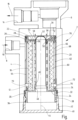
- the filter element of the embodiment of the filter device is shown in longitudinal section and the associated filter housing is shown in a schematically simplified longitudinal section.
- the filter housing 2 has a circular-cylindrical main part 4 and an upper head part 6 adjoining it.
- the fluid connection between outlet 14 and the main part 4 is not shown in detail.
- the filter element 18 accommodated in the circular cylindrical interior 12 of the main part 4 has an element material 20 in the form of a circular cylindrical hollow body, which is accommodated between an upper cap part 22 facing the head part 6 and a lower cap part 24.
- the upper cap part 22 has an annular groove 26 on the outer circumference in which an O-ring 28 sits, which seals the cap part 22 against the main housing part 4.
- an annular groove 30 is formed on the lower cap part 24 for an O-ring 32, which forms the seal of the lower cap part 24 on the main housing part 4.
- the lower cap part 24 which is injection-molded in one piece from a plastic material, has an annular surface 34, which forms the contact surface for the front end of the hollow body of the element material 20, a downwardly projecting extension 36 in the form of a hollow cylinder, coaxial with the longitudinal axis of the housing, which is connected via a steep thread 38 to a cover 40, which forms the bottom end of the main housing part 4 and can be secured thereto by means of a screw connection 42.
- the annular surface 34 of the cap part 24 is delimited radially on the inside by a nozzle 46 concentric with the longitudinal axis 44 of the housing, which merges into an upwardly adjoining hollow body 48.
- the hollow body 48 With its upper, closed end region, the hollow body 48 reaches through a central opening 50 in the upper cap part 22, the upper end 52 of the hollow body 48 protruding upwards beyond the opening 50 in the region of a trough-like depression 54 of the cap part 22.
- the opening 50 has individual projections 56 on the inside that project radially inwards.
- passage points are therefore formed between the opening 50 and the membrane of the hollow body 48, through which, as indicated by flow arrows 58, filtrate reaches the head part 6 and the filtrate outlet 14.
- the element material is supported by a fluid-permeable support tube 60 that surrounds the hollow body 48.
- the upper cap part 22 has a one-piece molded-on casing 62 which, with the exception of a thickened casing part 64, has the shape of a circular cylindrical hollow body.
- the outer and inner diameters of the casing 62 are dimensioned such that a first fluid chamber 66 is formed between the outside of the element material 20 and the inside of the casing 62 and a second, outer fluid chamber 68 is formed between the outside of the casing 62 and the main housing part 4.
- wall openings 70 are formed in the casing 62 in the base-side end region of the casing 62.
- the two fluid chambers 66, 68 form a type of communicating tube which, with the exception of the thickened casing part 64 with which the casing 62 rests against the inside of the housing, has a cylindrical structure coaxial with the longitudinal axis 44.
- the casing 62 forms the inflow surface, so that the outside of the element material 20 is not exposed to any radially acting flow pressure load in the event of pressure pulsations, but rather the unfiltered material flows in the axial direction in the inner fluid chamber 66, as indicated by the flow arrow 72.
- the hollow body 48 forms a compensator device which smooths out the pulsations.
- the interior of the hollow body 48 which is closed off by the base cover 40, can contain a compressible medium, such as air or N 2 .
- a compressible medium such as air or N 2 .
- the interior can be depressurized or provided with a, for example, low, filling pressure.
- the device according to the invention is largely freeze-proof, since only a small volume of fluid is enclosed in the fluid space 66, which acts on the element material 20 with freezing pressure when it freezes, while a freezing pressure developing in the outer fluid space 68 is absorbed by the jacket 62.
- the device according to the invention offers the possibility of blowing out the unfiltered material in the fluid spaces 66, 68 via the fluid inlet 8 when the device is switched off.
- a passage 76 is formed in a wall part 74 of the trough-like depression 54 of the upper cap part 22, which passage leads from the upper side of the cap part 22, which forms the filtrate side, to the fluid space 66.
- the filter material 20 of the filter element 18 is preferably provided with a fiber material which is essentially impermeable to air.
Landscapes
- Chemical & Material Sciences (AREA)
- Engineering & Computer Science (AREA)
- Chemical Kinetics & Catalysis (AREA)
- Combustion & Propulsion (AREA)
- Mechanical Engineering (AREA)
- General Engineering & Computer Science (AREA)
- Health & Medical Sciences (AREA)
- Toxicology (AREA)
- Environmental & Geological Engineering (AREA)
- Separation Using Semi-Permeable Membranes (AREA)
- Filtering Of Dispersed Particles In Gases (AREA)
Claims (15)
- Elément filtrant, qui a une matière (20) d'élément, qui s'étend entre deux parties (22, 24) de coiffe et qui s'appuie, du côté du pourtour intérieur, sur un dispositif (60) d'appui perméable au fluide, dans lequel un dispositif (48) compensateur est disposé à l'intérieur du dispositif (60) d'appui, caractérisé en ce qu'une partie (24) de coiffe est une partie constitutive monobloc du dispositif (48) compensateur.
- Elément filtrant suivant la revendication 1, caractérisé en ce que la matière (20) de l'élément est entourée, du côté du pourtour extérieur, d'une chemise (62) et est formée d'un cylindre creux, en ce que l'une des parties (22) de coiffe est une partie constitutive monobloc de la chemise (62) et l'autre partie (24) de coiffe est une partie constitutive monobloc du dispositif (48) compensateur, lequel, par un corps creux à paroi mince, traverse le dispositif d'appui sous la forme d'un tube (60) d'appui, ainsi que, par son extrémité (52) libre, avec formation d'un autre point (50, 56) de passage de fluide, traverse la partie de coiffe supérieure.
- Dispositif de filtration, comprenant un élément (18) filtrant suivant la revendication 1 ou 2, logé dans une enveloppe de filtre, à l'intérieur duquel est logé un dispositif (48) compensateur, caractérisé en ce que l'élément (18) filtrant est entouré, du côté du pourtour extérieur et à une distance radiale pouvant être donnée à l'avance, avec formation d'un espace (66) pour du fluide, de la chemise (62), qui est entourée, à son tour, à une distance radiale pouvant être donnée à l'avance, avec formation d'un autre espace (68) pour du fluide, de l'enveloppe (2) de filtre, et en ce que les deux espaces (66, 68) pour du fluide communiquent entre eux fluidiquement sous la forme de tubes communicants.
- Dispositif de filtration suivant la revendication 3, caractérisé en ce que les tubes (66, 68) communicants sont disposés coaxialement à l'axe (44) longitudinal de l'élément (18) filtrant et ont une structure cylindrique.
- Dispositif de filtration suivant la revendication 3 ou 4, caractérisé en ce que l'élément (18) filtrant a la matière (20) de l'élément s'étendant entre deux parties (22, 24) de coiffe, dont le côté de non filtrat ou d'afflux débouche dans l'un des espaces (66) pour du fluide et dont le côté de filtrat ou d'évacuation est tourné dans la direction du dispositif (48) compensateur.
- Dispositif de filtration suivant l'une des revendications 3 à 5, caractérisé en ce que la matière (20) de l'élément est sous la forme d'un cylindre creux, en ayant une pluralité de fibres de filtre, et est réalisée au moins en partie de manière imperméable à l'air, de préférence sensiblement imperméable à l'air, d'une manière particulièrement préférée complètement imperméable à l'air.
- Dispositif de filtration suivant l'une des revendications 3 à 6, caractérisé en ce que l'une des parties (22) de coiffe, notamment la partie supérieure est une partie constitutive monobloc de la chemise (62).
- Dispositif de filtration suivant l'une des revendications 3 à 7, caractérisé en ce que, pour ménager la communication fluidique entre les deux tubes (66, 68) communicants, la chemise (62) a, dans sa partie du pied, au moins un point (70) de passage de fluide.
- Dispositif de filtration suivant l'une des revendications 3 à 8, caractérisé en ce que la matière (20) de l'élément s'appuie sur le dispositif (60) d'appui, de l'extérieur vers l'intérieur, lors d'un passage de fluide.
- Dispositif de filtration suivant l'une des revendications 3 à 9, caractérisé en ce que les deux parties (22, 24) de coiffe sont rendues étanches vis-à-vis de l'enveloppe (2) du filtre au moyen d'un dispositif (28) d'étanchéité.
- Dispositif de filtration suivant l'une des revendications 3 à 10, caractérisé en ce que le dispositif compensateur dispose d'un corps (48) creux à paroi mince formé, de préférence en une matière plastique.
- Dispositif de filtration suivant l'une des revendications 3 à 11, caractérisé en ce que la partie (22) supérieure de coiffe de l'élément (18) filtrant est, avec formation d'au moins un autre point (50) de passage de fluide, traversée du côté de l'extrémité par le corps (48) creux, qui fait saillie, d'un dépassement pouvant être donné à l'avance, axialement au-dessus de la partie (22) supérieure de coiffe, et est fixé dans cette zone dans sa position de montage par la partie (22) supérieure de coiffe.
- Dispositif de filtration suivant l'une des revendications 3 à 12, caractérisé en ce que le dispositif d'appui perméable au fluide est formé d'un tube (60) d'appui, qui s'étend entre les deux parties (22, 24) de coiffe et qui entoure radialement le corps (48) creux.
- Dispositif de filtration suivant l'une des revendications 3 à 13, caractérisé en ce que l'enveloppe (2) de filtre a une entrée (8) pour du non filtrat, en particulier sous la forme d'une solution d'urée-eau polluée par des particules, qui est épurée des particules dans une direction de l'extérieur vers l'intérieur par la matière (20) de l'élément, et peut être évacué de l'enveloppe (2) de filtre par une sortie (14), et en ce que de l'air envoyé en sens contraire par la sortie (14), en contournant au moins en partie la matière (20) de l'élément, souffle le non filtrat resté dans l'enveloppe (2) de filtre au moins en partie en direction de l'entrée (8) de l'enveloppe (2) de filtre.
- Dispositif de filtration suivant l'une des revendications 3 à 14, caractérisé en ce que la partie (22) supérieure de coiffe est pourvue d'une autre matière (78) d'élément, qui sépare par filtration des particules d'un courant d'air et communique, sur son côté propre, avec l'espace (66) pour du fluide entre la chemise (62) et la une matière (20) de l'élément.
Applications Claiming Priority (1)
| Application Number | Priority Date | Filing Date | Title |
|---|---|---|---|
| DE102018007005.1A DE102018007005A1 (de) | 2018-09-05 | 2018-09-05 | Filtervorrichtung |
Publications (3)
| Publication Number | Publication Date |
|---|---|
| EP3620220A1 EP3620220A1 (fr) | 2020-03-11 |
| EP3620220C0 EP3620220C0 (fr) | 2025-02-12 |
| EP3620220B1 true EP3620220B1 (fr) | 2025-02-12 |
Family
ID=67777128
Family Applications (1)
| Application Number | Title | Priority Date | Filing Date |
|---|---|---|---|
| EP19193977.6A Active EP3620220B1 (fr) | 2018-09-05 | 2019-08-28 | Dispositif filtrant |
Country Status (2)
| Country | Link |
|---|---|
| EP (1) | EP3620220B1 (fr) |
| DE (1) | DE102018007005A1 (fr) |
Families Citing this family (7)
| Publication number | Priority date | Publication date | Assignee | Title |
|---|---|---|---|---|
| DE102019219383A1 (de) * | 2019-12-11 | 2021-06-17 | Mahle International Gmbh | Filtereinrichtung |
| DE102020204099A1 (de) * | 2020-03-30 | 2021-09-30 | Robert Bosch Gesellschaft mit beschränkter Haftung | Volumenausgleichselement für einen Filtereinsatz eines Flüssigkeitsfilters und Filtereinsatz mit einem derartigen Volumenausgleichselement |
| DE102021214647A1 (de) | 2021-12-20 | 2023-06-22 | Robert Bosch Gesellschaft mit beschränkter Haftung | Filterelement |
| DE102021214648A1 (de) | 2021-12-20 | 2023-06-22 | Robert Bosch Gesellschaft mit beschränkter Haftung | Filterelement |
| DE102021214655A1 (de) | 2021-12-20 | 2023-06-22 | Robert Bosch Gesellschaft mit beschränkter Haftung | Filterelement |
| DE102021214658A1 (de) | 2021-12-20 | 2023-06-22 | Robert Bosch Gesellschaft mit beschränkter Haftung | Bauteil für einen Flüssigkeitsfilter |
| DE102021214660A1 (de) | 2021-12-20 | 2023-06-22 | Robert Bosch Gesellschaft mit beschränkter Haftung | Flüssigkeitsfilter |
Citations (1)
| Publication number | Priority date | Publication date | Assignee | Title |
|---|---|---|---|---|
| US20180195475A1 (en) * | 2016-12-19 | 2018-07-12 | Champion Laboratories, Inc. | Filter assembly |
Family Cites Families (7)
| Publication number | Priority date | Publication date | Assignee | Title |
|---|---|---|---|---|
| US2886180A (en) * | 1956-03-19 | 1959-05-12 | Caterpillar Tractor Co | Full flow filter with oil retaining means |
| US3272336A (en) * | 1965-04-05 | 1966-09-13 | Wix Corp | Liquid purifier and cleaner |
| DE102012223009A1 (de) * | 2012-12-13 | 2014-06-18 | Robert Bosch Gmbh | Vorrichtung zur Dämpfung von Druckschwankungen in einem Fluid |
| DE102012223028B4 (de) | 2012-12-13 | 2024-06-13 | Robert Bosch Gmbh | Vorrichtung zur Dämpfung von Druckschwankungen in einem Fluid |
| DE102015010562A1 (de) * | 2015-08-12 | 2017-02-16 | Hydac Filtertechnik Gmbh | Filtervorrichtung nebst Filterelement |
| DE102015010532A1 (de) * | 2015-08-12 | 2017-02-16 | Hydac Filtertechnik Gmbh | Filtervorrichtung nebst Filterelement |
| DE102015010533A1 (de) * | 2015-08-12 | 2017-02-16 | Hydac Filtertechnik Gmbh | Filtervorrichtung nebst Filterelement |
-
2018
- 2018-09-05 DE DE102018007005.1A patent/DE102018007005A1/de not_active Withdrawn
-
2019
- 2019-08-28 EP EP19193977.6A patent/EP3620220B1/fr active Active
Patent Citations (1)
| Publication number | Priority date | Publication date | Assignee | Title |
|---|---|---|---|---|
| US20180195475A1 (en) * | 2016-12-19 | 2018-07-12 | Champion Laboratories, Inc. | Filter assembly |
Also Published As
| Publication number | Publication date |
|---|---|
| EP3620220C0 (fr) | 2025-02-12 |
| DE102018007005A1 (de) | 2020-03-05 |
| EP3620220A1 (fr) | 2020-03-11 |
Similar Documents
| Publication | Publication Date | Title |
|---|---|---|
| EP3620220B1 (fr) | Dispositif filtrant | |
| EP2542322B1 (fr) | Dispositif de filtration | |
| EP3525910B1 (fr) | Installation de filtre et élément de filtre rond, en particulier pour la filtration de gaz | |
| WO2014191476A1 (fr) | Élément filtrant et système de filtration muni d'un élément filtrant | |
| DE102009014435A1 (de) | Abgasbehandlungseinrichtung | |
| WO2014082762A1 (fr) | Filtre, élément filtrant, boîtier de filtre et dispositif de purge d'un filtre | |
| EP3298254B1 (fr) | Système d'échappement avec capteur de gaz, en particulier avec un capteur de matières particulaires | |
| DE112014005458B4 (de) | Filterelement und Filtersystem mit Nebenstromfilterung | |
| DE102013015143B4 (de) | Filter für Fluid, Filterelement und Filtergehäuse eines Filters | |
| EP3145618B1 (fr) | Dispositif de filtration | |
| WO2015082117A1 (fr) | Dispositif de filtrage avec adaptateur | |
| WO2019110361A1 (fr) | Élément filtrant rond d'un filtre pour solution aqueuse d'urée et filtre | |
| DE10063283A1 (de) | Siebfilter für Fluidleitungen, insbesondere für hydraulische Druckleitungen in Brennkraftmaschinen | |
| EP3727643B1 (fr) | Élément filtrant d'un filtre à liquide et filtre | |
| EP4093530B1 (fr) | Filtre pour filtrer a fluide, soupape de dérivation pour filtre et diffuseur pour filtre | |
| EP3334515B1 (fr) | Dispositif filtrant | |
| EP4146366A1 (fr) | Appareil de filtration | |
| DE102017011437A1 (de) | Filter einer Filtervorrichtung zur Filtrierung von Fluid und Filterkopf einer Filtervorrichtung | |
| DE9315839U1 (de) | Flüssigkeitsfilter für Kraftstoff | |
| WO2020043511A1 (fr) | Dispositif de filtration, élément filtrant et élément adaptateur | |
| EP2577010B1 (fr) | Dispositif de stockage de fluide | |
| DE102022209308A1 (de) | Filterelement | |
| DE102020115068A1 (de) | Filterelement, Dichtungsendscheibe eines Filterelements und Filter | |
| WO2016008776A1 (fr) | Élément de filtration creux d'un filtre pour fluide, filtre et boîtier de filtre | |
| DE102013004865A1 (de) | Filtereinrichtung mit einem ringförmigen Filterelement |
Legal Events
| Date | Code | Title | Description |
|---|---|---|---|
| PUAI | Public reference made under article 153(3) epc to a published international application that has entered the european phase |
Free format text: ORIGINAL CODE: 0009012 |
|
| STAA | Information on the status of an ep patent application or granted ep patent |
Free format text: STATUS: THE APPLICATION HAS BEEN PUBLISHED |
|
| AK | Designated contracting states |
Kind code of ref document: A1 Designated state(s): AL AT BE BG CH CY CZ DE DK EE ES FI FR GB GR HR HU IE IS IT LI LT LU LV MC MK MT NL NO PL PT RO RS SE SI SK SM TR |
|
| AX | Request for extension of the european patent |
Extension state: BA ME |
|
| STAA | Information on the status of an ep patent application or granted ep patent |
Free format text: STATUS: REQUEST FOR EXAMINATION WAS MADE |
|
| 17P | Request for examination filed |
Effective date: 20200911 |
|
| RBV | Designated contracting states (corrected) |
Designated state(s): AL AT BE BG CH CY CZ DE DK EE ES FI FR GB GR HR HU IE IS IT LI LT LU LV MC MK MT NL NO PL PT RO RS SE SI SK SM TR |
|
| STAA | Information on the status of an ep patent application or granted ep patent |
Free format text: STATUS: EXAMINATION IS IN PROGRESS |
|
| RAP3 | Party data changed (applicant data changed or rights of an application transferred) |
Owner name: HYDAC FILTERTECHNIK GMBH |
|
| 17Q | First examination report despatched |
Effective date: 20210922 |
|
| REG | Reference to a national code |
Ref country code: DE Ref legal event code: R079 Free format text: PREVIOUS MAIN CLASS: B01D0029150000 Ipc: F01N0003200000 Ref country code: DE Ref legal event code: R079 Ref document number: 502019012908 Country of ref document: DE Free format text: PREVIOUS MAIN CLASS: B01D0029150000 Ipc: F01N0003200000 |
|
| RIC1 | Information provided on ipc code assigned before grant |
Ipc: B01D 29/15 20060101ALI20230208BHEP Ipc: B01D 29/90 20060101ALI20230208BHEP Ipc: B01D 35/31 20060101ALI20230208BHEP Ipc: F16L 41/02 20060101ALI20230208BHEP Ipc: F01N 13/00 20100101ALI20230208BHEP Ipc: F01N 3/20 20060101AFI20230208BHEP |
|
| GRAP | Despatch of communication of intention to grant a patent |
Free format text: ORIGINAL CODE: EPIDOSNIGR1 |
|
| STAA | Information on the status of an ep patent application or granted ep patent |
Free format text: STATUS: GRANT OF PATENT IS INTENDED |
|
| INTG | Intention to grant announced |
Effective date: 20241010 |
|
| GRAS | Grant fee paid |
Free format text: ORIGINAL CODE: EPIDOSNIGR3 |
|
| GRAA | (expected) grant |
Free format text: ORIGINAL CODE: 0009210 |
|
| STAA | Information on the status of an ep patent application or granted ep patent |
Free format text: STATUS: THE PATENT HAS BEEN GRANTED |
|
| AK | Designated contracting states |
Kind code of ref document: B1 Designated state(s): AL AT BE BG CH CY CZ DE DK EE ES FI FR GB GR HR HU IE IS IT LI LT LU LV MC MK MT NL NO PL PT RO RS SE SI SK SM TR |
|
| REG | Reference to a national code |
Ref country code: GB Ref legal event code: FG4D Free format text: NOT ENGLISH |
|
| REG | Reference to a national code |
Ref country code: CH Ref legal event code: EP |
|
| REG | Reference to a national code |
Ref country code: DE Ref legal event code: R096 Ref document number: 502019012908 Country of ref document: DE |
|
| REG | Reference to a national code |
Ref country code: IE Ref legal event code: FG4D Free format text: LANGUAGE OF EP DOCUMENT: GERMAN |
|
| U01 | Request for unitary effect filed |
Effective date: 20250212 |
|
| U07 | Unitary effect registered |
Designated state(s): AT BE BG DE DK EE FI FR IT LT LU LV MT NL PT RO SE SI Effective date: 20250218 |
|
| PG25 | Lapsed in a contracting state [announced via postgrant information from national office to epo] |
Ref country code: RS Free format text: LAPSE BECAUSE OF FAILURE TO SUBMIT A TRANSLATION OF THE DESCRIPTION OR TO PAY THE FEE WITHIN THE PRESCRIBED TIME-LIMIT Effective date: 20250512 |
|
| PG25 | Lapsed in a contracting state [announced via postgrant information from national office to epo] |
Ref country code: PL Free format text: LAPSE BECAUSE OF FAILURE TO SUBMIT A TRANSLATION OF THE DESCRIPTION OR TO PAY THE FEE WITHIN THE PRESCRIBED TIME-LIMIT Effective date: 20250212 |
|
| PG25 | Lapsed in a contracting state [announced via postgrant information from national office to epo] |
Ref country code: ES Free format text: LAPSE BECAUSE OF FAILURE TO SUBMIT A TRANSLATION OF THE DESCRIPTION OR TO PAY THE FEE WITHIN THE PRESCRIBED TIME-LIMIT Effective date: 20250212 |
|
| PGFP | Annual fee paid to national office [announced via postgrant information from national office to epo] |
Ref country code: GB Payment date: 20250611 Year of fee payment: 7 |
|
| PG25 | Lapsed in a contracting state [announced via postgrant information from national office to epo] |
Ref country code: IS Free format text: LAPSE BECAUSE OF FAILURE TO SUBMIT A TRANSLATION OF THE DESCRIPTION OR TO PAY THE FEE WITHIN THE PRESCRIBED TIME-LIMIT Effective date: 20250612 Ref country code: NO Free format text: LAPSE BECAUSE OF FAILURE TO SUBMIT A TRANSLATION OF THE DESCRIPTION OR TO PAY THE FEE WITHIN THE PRESCRIBED TIME-LIMIT Effective date: 20250512 |
|
| PG25 | Lapsed in a contracting state [announced via postgrant information from national office to epo] |
Ref country code: HR Free format text: LAPSE BECAUSE OF FAILURE TO SUBMIT A TRANSLATION OF THE DESCRIPTION OR TO PAY THE FEE WITHIN THE PRESCRIBED TIME-LIMIT Effective date: 20250212 |
|
| PG25 | Lapsed in a contracting state [announced via postgrant information from national office to epo] |
Ref country code: GR Free format text: LAPSE BECAUSE OF FAILURE TO SUBMIT A TRANSLATION OF THE DESCRIPTION OR TO PAY THE FEE WITHIN THE PRESCRIBED TIME-LIMIT Effective date: 20250513 |
|
| PG25 | Lapsed in a contracting state [announced via postgrant information from national office to epo] |
Ref country code: SM Free format text: LAPSE BECAUSE OF FAILURE TO SUBMIT A TRANSLATION OF THE DESCRIPTION OR TO PAY THE FEE WITHIN THE PRESCRIBED TIME-LIMIT Effective date: 20250212 |
|
| U20 | Renewal fee for the european patent with unitary effect paid |
Year of fee payment: 7 Effective date: 20250901 |
|
| PG25 | Lapsed in a contracting state [announced via postgrant information from national office to epo] |
Ref country code: CZ Free format text: LAPSE BECAUSE OF FAILURE TO SUBMIT A TRANSLATION OF THE DESCRIPTION OR TO PAY THE FEE WITHIN THE PRESCRIBED TIME-LIMIT Effective date: 20250212 |
|
| PG25 | Lapsed in a contracting state [announced via postgrant information from national office to epo] |
Ref country code: SK Free format text: LAPSE BECAUSE OF FAILURE TO SUBMIT A TRANSLATION OF THE DESCRIPTION OR TO PAY THE FEE WITHIN THE PRESCRIBED TIME-LIMIT Effective date: 20250212 |
|
| PLBE | No opposition filed within time limit |
Free format text: ORIGINAL CODE: 0009261 |
|
| STAA | Information on the status of an ep patent application or granted ep patent |
Free format text: STATUS: NO OPPOSITION FILED WITHIN TIME LIMIT |
|
| REG | Reference to a national code |
Ref country code: CH Ref legal event code: L10 Free format text: ST27 STATUS EVENT CODE: U-0-0-L10-L00 (AS PROVIDED BY THE NATIONAL OFFICE) Effective date: 20251224 |
|
| 26N | No opposition filed |
Effective date: 20251113 |
|
| REG | Reference to a national code |
Ref country code: CH Ref legal event code: H13 Free format text: ST27 STATUS EVENT CODE: U-0-0-H10-H13 (AS PROVIDED BY THE NATIONAL OFFICE) Effective date: 20260324 |
|
| PG25 | Lapsed in a contracting state [announced via postgrant information from national office to epo] |
Ref country code: MC Free format text: LAPSE BECAUSE OF FAILURE TO SUBMIT A TRANSLATION OF THE DESCRIPTION OR TO PAY THE FEE WITHIN THE PRESCRIBED TIME-LIMIT Effective date: 20250212 |