EP3620260A1 - Dispositif compensateur permettant de compenser une tolérance de positionnement - Google Patents
Dispositif compensateur permettant de compenser une tolérance de positionnement Download PDFInfo
- Publication number
- EP3620260A1 EP3620260A1 EP19192091.7A EP19192091A EP3620260A1 EP 3620260 A1 EP3620260 A1 EP 3620260A1 EP 19192091 A EP19192091 A EP 19192091A EP 3620260 A1 EP3620260 A1 EP 3620260A1
- Authority
- EP
- European Patent Office
- Prior art keywords
- carrier
- base
- compensation device
- clamping
- working
- Prior art date
- Legal status (The legal status is an assumption and is not a legal conclusion. Google has not performed a legal analysis and makes no representation as to the accuracy of the status listed.)
- Granted
Links
Images





Classifications
-
- B—PERFORMING OPERATIONS; TRANSPORTING
- B23—MACHINE TOOLS; METAL-WORKING NOT OTHERWISE PROVIDED FOR
- B23Q—DETAILS, COMPONENTS, OR ACCESSORIES FOR MACHINE TOOLS, e.g. ARRANGEMENTS FOR COPYING OR CONTROLLING; MACHINE TOOLS IN GENERAL CHARACTERISED BY THE CONSTRUCTION OF PARTICULAR DETAILS OR COMPONENTS; COMBINATIONS OR ASSOCIATIONS OF METAL-WORKING MACHINES, NOT DIRECTED TO A PARTICULAR RESULT
- B23Q1/00—Members which are comprised in the general build-up of a form of machine, particularly relatively large fixed members
- B23Q1/0063—Connecting non-slidable parts of machine tools to each other
-
- B—PERFORMING OPERATIONS; TRANSPORTING
- B23—MACHINE TOOLS; METAL-WORKING NOT OTHERWISE PROVIDED FOR
- B23Q—DETAILS, COMPONENTS, OR ACCESSORIES FOR MACHINE TOOLS, e.g. ARRANGEMENTS FOR COPYING OR CONTROLLING; MACHINE TOOLS IN GENERAL CHARACTERISED BY THE CONSTRUCTION OF PARTICULAR DETAILS OR COMPONENTS; COMBINATIONS OR ASSOCIATIONS OF METAL-WORKING MACHINES, NOT DIRECTED TO A PARTICULAR RESULT
- B23Q3/00—Devices holding, supporting, or positioning work or tools, of a kind normally removable from the machine
- B23Q3/02—Devices holding, supporting, or positioning work or tools, of a kind normally removable from the machine for mounting on a work-table, tool-slide, or analogous part
- B23Q3/10—Auxiliary devices, e.g. bolsters, extension members
- B23Q3/103—Constructional elements used for constructing work holders
Definitions
- the present invention relates to the technical field of working devices, for example clamping devices, which have to be positioned as precisely as possible in order to carry out a machining process on a workpiece or on several workpieces relative to a substrate, for example relative to a machine table or a clamping plate.
- such a working device is, for example, a clamping device that has a receptacle in which a retractable nipple, which is arranged on a workpiece or on a workpiece pallet, can be locked
- it can be due to positioning tolerances of the retractable nipple on the workpiece pallet or on the workpiece and / or due to positioning tolerances of several such clamping devices relative to the substrate, that the relative positions of the retractable nipples on the workpiece pallet or on the workpiece on the one hand and the relative positions of the receptacles of the several clamping devices on the other hand differ so much that not all retractable nipples can be inserted simultaneously into the associated receptacle of a tensioning device.
- the present invention has for its object to be able to compensate for such position tolerances of a work device to be positioned.
- a compensation device for compensating for a positioning tolerance of a work device to be positioned, which comprises a base and a carrier, wherein the carrier comprises a fastening device for fastening the working device to the carrier and the carrier along at least one Sliding direction is slidably held on the base relative to the base, wherein the compensation device comprises a locking device for locking the carrier in a working position relative to the base.
- the working device can be designed, for example, as a clamping device, in particular as a quick clamping device, particularly preferably as a zero point quick clamping device.
- Such a clamping device can in particular have a receptacle for a respective retractable nipple and a locking device for locking the respective retractable nipple in the receptacle.
- the locking device of the tensioning device can be actuated mechanically, pneumatically or hydraulically, for example.
- the carrier is displaceable relative to the base along at least two mutually perpendicular displacement directions which together span a displacement plane.
- the locking device can in particular comprise a clamping device for clamping the carrier to the base.
- Such a clamping device can comprise at least one wedge element.
- At least one wedge element preferably has at least one wedge surface with a wedge angle of less than 10 °, in particular less than 8 °, particularly preferably less than 6 °.
- the wedge angle ⁇ is the angle at which the wedge surface is inclined with respect to a direction of movement of the wedge element and / or with respect to a displacement plane along which the carrier can be displaced relative to the base of the compensation device.
- the clamping device preferably comprises a movement device for generating a linear movement of at least one wedge element.
- Such a movement device can in particular comprise a conversion device for converting a rotary movement of an actuating element into a linear movement of at least one wedge element.
- the clamping device comprises a pneumatic, hydraulic or electromotive movement device for generating a linear movement of at least one wedge element.
- a pneumatic or hydraulic movement device can in particular comprise a piston which is coupled to the respectively associated wedge element and which is displaceably guided in a cylinder which can be acted upon by a pressure fluid.
- the compensating device comprises a foot part, by means of which the compensating device can be fixed on a base, for example on a machine table or on a clamping plate.
- the base in particular the machine table or the clamping plate, preferably has at least one T-slot, particularly preferably a plurality of T-slots.
- the foot part can be formed in one piece with a base body of the base of the compensation device or can be designed as a component which is produced separately from the base body of the base.
- the foot part can have at least one, preferably two or more, guide channels.
- Such a guide channel can serve to guide an anchoring element, by means of which the foot part can be anchored to a base, for example on a machine table or on a clamping plate, relative to the base of the compensating device.
- Such a guide channel can be curved, in particular curved in the shape of a circular arc.
- the base comprises a base body which has an at least partially essentially cylindrical peripheral surface.
- the compensation device preferably comprises at least one clamp element, particularly preferably two or more clamp elements, between which an area of the carrier and an area of the base and optionally one or more further elements, for example a wedge element, of the compensation device are arranged.
- the carrier and the base can be clamped against one another by a movement of the at least one wedge element relative to the clamp element and / or relative to the base.
- the compensation device comprises at least one tension bolt and a nut arranged thereon for clamping the carrier and base.
- the carrier has at least one receiving bore in which the draw bolt is received with play. This play enables the carrier to be moved relative to the base of the balancer when the balancer is in an open state.
- the fastening device for fastening the working device to the carrier can comprise at least one threaded hole, preferably two or more threaded holes.
- the carrier preferably has a substantially flat contact surface for placing the working device on the carrier.
- the compensation device according to the invention is particularly suitable for use in a combination of a compensation device according to the invention and a working device which can be fastened or fastened to the carrier.
- the working device is a clamping device for clamping a workpiece or a workpiece pallet.
- the compensation device according to the invention is also suitable for use in a combination of several working devices and at least one compensation device.
- At least one of the working devices can preferably be fastened or fastened to the carrier of the compensating device.
- Such a combination can further comprise a workpiece or a workpiece pallet, the workpiece or the workpiece pallet being coupled to each of the plurality of working devices.
- the workpiece or the workpiece pallet is provided with a plurality of retractable nipples, the workpiece or the workpiece pallet being coupled to each of the plurality of working devices, which are in particular designed as clamping devices, by locking a respective retracting nipple to the relevant working device, in particular the clamping device is.
- a machining operation for example machining, can be carried out on the workpiece or on one or more workpieces which are arranged on the workpiece pallet.
- the compensation device can be brought into an open state in which the carrier can be displaced into one working position along one or more displacement directions (X direction, Y direction) relative to the base.
- the compensation device can be brought into a tensioned state, in which the carrier is locked to the base in the working position, so that the carrier can no longer move relative to the base.
- the actuation of the compensating device in particular the transfer of the compensating device from the clamped state into the open state and / or from the open state to the clamped state, can be carried out mechanically using a suitable tool, for example using a torque wrench.
- the transfer of the compensating device from the tensioned state into the open state and / or from the open state to the tensioned state takes place pneumatically or hydraulically using a cylinder which is pressurized with a pressure fluid.
- the compensation device can have one or more tension bolts, by means of which the carrier and the base can be clamped against one another.
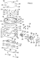
- the clamping assembly shown as a whole with 100, comprises a plurality, preferably two or more, for example four, clamping devices 102, which are each held by a base 104 on a base 108 provided with T-grooves 106, for example a machine table 110 or a clamping plate.
- Each of the clamping devices 102 is preferably designed as a quick clamping device, in particular as a zero point quick clamping device.
- Each tensioning device 102 can in particular have a receptacle 112 for a respective pull-in nipple (not shown) and a locking device for locking the respective pull-in nipple in the receptacle 112.
- the clamping device 102 shown in the drawing is the locking device of the respective clamping device 102 mechanically, by turning an actuating screw 114, from a locking position in which the respective retractable nipple is locked in the receptacle 112 of the respective tensioning device 102 to an unlocked position in which the retractable nipple from the receptacle 112 can be removed, and / or can be transferred from the unlocking position into the locking position.
- the locking device of the respective tensioning device 102 is actuated pneumatically or hydraulically.
- the retractable nipples which are inserted into the receptacles 112 of the plurality of clamping devices 102 are preferably attached to the same workpiece pallet (not shown) or to the same workpiece (not shown) to be clamped.
- At least one base 104 of the clamping assembly 100 is designed as a compensating device 116 for compensating for a positioning tolerance of the clamping device 102 to be arranged on the compensating device 116.
- two or more bases 104 of the clamping assembly 100 in particular also all bases 104 of the clamping assembly 100, to be designed as such a compensation device 116.
- the compensation device 116 comprises a base 118 and a carrier 120, the carrier 120 comprising a fastening device 122 for fastening a working device 124, for example a clamping device 102, to the carrier 120 and the carrier 120 along a first displacement direction 126 (X Direction) and a second displacement direction 128 (Y direction) oriented perpendicular to the first displacement direction 126 is held on the base 118 so as to be displaceable relative to the base 118.
- X Direction first displacement direction 126
- Y direction second displacement direction 128
- the first displacement direction 126 (X direction) and the second displacement direction 128 (Y direction) are preferably both aligned perpendicular to an axis direction 130 (Z direction) of the compensation device 116 and together span a displacement plane (XY plane), along which the carrier 120 is slidable relative to the base 118.
- Compensating device 116 further includes a locking device 132 for locking carrier 120 in a desired working position relative to base 118.
- the locking device 132 is preferably designed as a clamping device 134 for clamping the carrier 120 to the base 118.
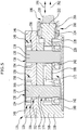
- the clamping device 134 comprises one or more clamp elements 136, each clamp element 136 comprising, for example, a draw bolt 138 and a nut 142 engaging in an external thread 140 of the draw bolt 138 with an internal thread 144 designed to complement the external thread 140 of the draw bolt 138.
- the carrier 120 comprises a carrier disk 146, which has a stepped receiving bore 148 assigned to each of the draw bolts 138.
- the receiving bore 148 includes an upper portion 150 of larger diameter and a lower portion 152 of smaller diameter.
- the bolt head 154 of the respective pull bolt 138 lies in (in Fig. 6 illustrated) tensioned state of the compensating device 116 at a step 156 at which the upper section 150 merges into the lower section 152 of the receiving bore 148.
- the working device 124 can be fixed in any position relative to the vertical on the compensating device 116, in particular above, below or to the side of the compensating device 116.
- the receiving bore 148 is covered on its top by a cover 158.
- the cover 158 has one or more fastener passage openings 160, each of which is aligned with a threaded hole 162 in the carrier disk 146.
- Fastening screws 164 which pass through the clamping device 102, can be inserted into the threaded holes 162 (see Fig. 1 ) are screwed in to fix the tensioning device 102 to the carrier 120, wherein the tensioning device 102 bears against a contact surface 166 of the compensating device 116 formed by the upper side of the cover 158.
- the threaded holes 162 and the fastener passage openings 160 of the cover 158 thus form part of the fastening device 122 of the compensating device 116.
- the carrier disk 146 is preferably essentially cylindrical.
- the base 118 of the compensating device 116 comprises a base body 168, which preferably has a cylindrical peripheral surface 170, the diameter of which preferably substantially corresponds to the diameter of the carrier disk 146.
- the base body 168 is provided on its underside with a recess 172, into which two bolt passage openings 174 open, which extend downward from an essentially flat upper side 176 of the base body 168 along the axis direction 130 (Z direction) of the compensating device 116 .
- the nut 142 screwed onto the external thread 140 at the lower end of the shaft 178 is received within the recess 172 of the base body 168.
- the recess 172 is closed at the bottom by means of a cover 180, which can be held on the base body 168, for example, by screwing.
- the cover 180 can have one or more screw passage openings 182, through which a screw 184 extends into a respectively assigned threaded hole 186 of the base body 168.
- a wedge element 188 is further arranged in the recess 172 of the base 118 and has one or more wedge surfaces 190 on the wedge element side.
- each of the wedge element-side wedge surfaces 190 is inclined by a small acute angle ⁇ relative to the displacement plane (XY plane) spanned by the first displacement direction 126 (X direction) and the second displacement direction 128 (Y direction), wherein ⁇ is preferably less than 10 °, in particular less than 8 °, particularly preferably less than 6 °.
- ⁇ is approximately 5 ° (with a tolerance of +/- 30 minutes).
- each of the wedge element-side wedge surfaces 190 cooperates with a respective base-side wedge surface 192, which is preferably on an upper side of the recess 172 in the base body 168 of the base 118 is arranged.
- Each of the base-side wedge surfaces 192 is inclined relative to the displacement plane (XY plane) of the compensating device 116 spanned by the first displacement direction 126 (X direction) and the second displacement direction 128 (Y direction) by essentially the same angle ⁇ as the respectively assigned wedge element side Wedge surface 190.
- the wedge angle ⁇ 'of the base-side wedge surfaces 192 is preferably less than 10 °, in particular less than 8 °, particularly preferably less than 6 °.
- the wedge angle ⁇ 'of the base-side wedge surfaces 192 can be approximately 5 ° (with a tolerance of, for example, +/- 30 minutes).
- a wedge surface 190 on the wedge element side and a wedge surface 192 on the base side preferably lie essentially flat against one another and can slide against one another if the wedge element 180 relative to the base 118 from the in FIG Fig. 7 shown open position in the Fig. 8 shown tensioned position or is transferred from the tensioned position to the open position.
- the wedge element 188 has a passage opening 194 for each clamp element 136, through which the shaft 178 of the draw bolt 138 of the clamp element 136 in question extends.
- each clamp element 136 On opposite sides of each clamp element 136, a pair of wedge element-side wedge surfaces 190 and a pair of base-side wedge surface 192 interacting with these wedge element-side wedge surfaces 190 are preferably provided.
- the clamping device 134 comprises a movement device 198.
- the movement device 198 in turn comprises a conversion device 200 for converting a rotary movement of an actuating element 202 into a linear movement of a driver element 204, which is non-rotatably connected to the wedge element 188, and thus into a linear movement of the wedge element 188.
- the actuating element 202 comprises a threaded sleeve 206 with an annular collar 208, which is secured to the base body 168 of the base 118 by an attachment 210, the threaded sleeve 206 being rotatably mounted about its longitudinal axis in a through bore 212 of the attachment 210 and the annular collar 208 being an undercut forms which retains the actuating element 202 in a position between the base body 168 and the attachment 210.
- the attachment 210 can be fixed to the base body 168 by means of one or more screws 214, which each penetrate a screw passage opening 216 on the attachment 210 and are screwed into a respectively assigned threaded hole 218 on the base body 168.
- the actuating element 202 On its outward-facing end face, the actuating element 202 has an actuating head 220, on which an operator can engage by means of a suitable tool in order to rotate the actuating element 202 about its longitudinal axis.
- the actuating head 220 can have a polygonal cross section, for example, and is designed, for example, as a hexagon.
- a threaded section 222 of the driver element 204 is in engagement with an internal thread 224 of the threaded sleeve 206.
- the driver element 204 further comprises an undercut section 226 facing away from the threaded section 222 and a connecting section 228 connecting the undercut section 226 to the threaded section 222.
- the wedge element 188 has at its end facing the driver element 204 a slot 230, which is penetrated by the connecting section 228 of the driver element 204, the undercut section 226 being located in one of the passage openings 194 of the wedge element 188.
- the driver element 204 is thus suspended on the wedge element 188 such that it is coupled to the wedge element 188 essentially without play in the direction of movement 196.
- the connecting section 228 bears with two of its side surfaces on mutually opposite boundary surfaces of the slot 230, so that the driver element 204 is secured against rotation relative to the wedge element 188 and thus relative to the base 118.
- receptacles 234 which are essentially in the form of cylindrical sections are provided on the side walls 232 of the recess 172 in the base body 168, each of which has a section a nut 142 receive one of the clamp elements 136, so that the nuts 142 and thus the clamp elements 136 are secured against displacement along the direction of movement 196 of the wedge element 188.
- the compensation device 116 further comprises a foot part 236 (see Fig. 1 ), which can be formed in one piece with the base body 168 or as a component manufactured separately from the base body 168 of the base 118.
- the base body 168 is detachably connected to the foot part 236 by means of fastening means (not shown), for example fastening screws, the fastening means extending through fastening means through openings 238 in the base body 168 into threaded holes (not shown) provided on the foot part 236 are extending into it.
- fastening means for example fastening screws
- the fastening means also extend through passage openings 240 in the carrier disk 146 and through recesses 242 in the cover 158 of the carrier 120, screw heads of the fastening means being received in the passage openings 240 and the recesses 242 so that the working device 124, in particular the clamping device 102, can be placed with its underside flat on the contact surface 166 on the top of the cover 158.
- the foot part 236 of the compensating device 116 can have one or more guide channels 244, in each of which an anchoring element 246 is slidably guided along a longitudinal direction of the relevant guide channel 244.
- Each anchoring element 246 can comprise, for example, an anchoring screw 248, which passes through a passage opening in a washer 250 and the guide channel 244 and into one (not ) T-nut nut is screwed, which is arranged in one of the T-grooves 106 of the machine table 110 or a clamping plate in order to fix the compensation device 116 on the machine table 110 or on the clamping plate.
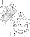
- the compensation device 116 further comprises a reset device 252, by means of which the carrier 120 relative to the base 118 in the in Fig. 14
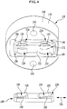
- the starting position shown can be reset, in which the carrier 120 is centered on the base 118, so that in particular a central axis 254 of the carrier 120 oriented perpendicular to the displacement plane (XY plane) of the compensating device 116 with a likewise perpendicular to the displacement plane (XY plane) and central axis 256 of the base 118 aligned parallel to the Z direction of the compensating device 116 coincides (see Fig. 14 ).
- Such a reset device 252 can comprise, for example, one or more reset elements 258, which are held on the base 118 or on the carrier 120 and extend into a reset recess 260 on the respective other component, that is to say on the carrier 120 or on the base 118 .
- the restoring elements 258 are deformed, preferably essentially elastically, so that a, preferably elastic, restoring force is generated, which is so is directed that the carrier 120 is moved back to the starting position after releasing its locking on the base 118.
- Such a reset element 258 can in particular comprise an elastomer material or be formed entirely from an elastomer material.
- the compensation device 116 described above works as follows: In order to compensate for a positioning tolerance of a working device 124 positioned on the compensating device 116 or of a working device 124 still to be positioned on the compensating device 116, for example a clamping device 102, the compensating device 116 is shown in FIGS Fig. 5 transferred open state shown by the actuating element 102, for example by means of a multi-sided key acting on the actuating head 220, in the opening direction, for example counterclockwise, which has the consequence that the driver element 204 and the wedge element 188 coupled thereto along the direction of movement 196 of the movement device 198 in an opening direction 262 (see Fig. 5 ) are moved, which in the exemplary embodiment shown is directed outwards from the wedge element 188 towards the actuating element 202.
- This movement of the wedge element 188 in the opening direction 262 pulls off the wedge element side wedge surfaces 190 from the respectively assigned base-side wedge surfaces 192, that is to say moves relative to the base-side wedge surfaces 192 in such a way that the total height of the elements clasped by the clamp elements 136, namely the wedge element 188 , the base body 168 and the carrier disk 146, in the area lying between the respective nut 142 and the bolt head 154 of the respective draw bolt 138 is reduced.
- the carrier 120 can thus in this open position from the starting position, into which the carrier 120 is biased by the reset device 252, along the first displacement direction 126 (X direction) and / or along the second displacement direction 128 (Y direction) as far be displaced, as is permitted by the play of the draw bolts 138 in their receiving bores 148.
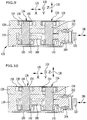
- a state of the compensation device 116 is shown, in which the carrier 120 relative to the base 118 in the first displacement direction 126 (X direction) maximally towards the actuating element 202 (in FIG Fig. 9 to the right).
- FIG. 10 A state of the compensation device 116 is shown, in which the carrier 120 relative to the base 118 in the first displacement direction 126 (X direction) maximally away from the actuating element 202 (in FIG Fig. 10 to the left).
- FIG. 11 A state of the compensation device 116 is shown in which the carrier 120 is displaced to the right as far as possible relative to the base 118 in the second displacement direction 128 (Y direction).
- FIG. 12 A state of the compensation device 116 is shown, in which the carrier 120 is displaced to the left relative to the base 118 along the second displacement direction 128 (Y direction).
- the extent of the respective displacement along the first displacement direction 126 (X direction) and / or along the second displacement direction 128 (Y direction) is chosen such that the working device 124 fixed on the carrier 120 or that still to be fixed on the carrier 120 Work device 124 in the desired manner relative to that Base 108, for example the machine table 110 or a clamping plate, and thus positioned relative to the other working devices 124 of the clamping assembly 100.
- the carrier 120 is locked relative to the base 118 by the compensating device 116 in the in FIGS Fig. 6 , 8th and 9 to 12 shown tensioned state is transferred.
- actuating element 202 is rotated in the clamping direction, for example clockwise, using a suitable tool, for example a polygonal key, so that the driver element 204 and the wedge element 188 coupled thereto are moved in the clamping direction 264 along the direction of movement 196, for example in the direction away from the actuator 202.
- a suitable tool for example a polygonal key
- the wedge element-side wedge surfaces 190 are pushed onto the base-side wedge surfaces 192, that is to say moved relative to the base-side wedge surfaces 192, in such a way that the total height of the elements surrounded by the clamp elements 136, namely the wedge element 188, the base body 168 and the carrier disk 146, in the between the bolt head 154 of the respective draw bolt 138 and the nut 142 of the respective clamp element 136 increases.
- the working device 124 for example a clamping device 102
- the working device 124 is now placed on the contact surface 166 of the Compensating device 116 placed and fixed by screwing the fastening screws into the threaded holes 162 of the carrier 120 on the carrier 120 of the compensating device 116.
- a workpiece provided with retractable nipples or a workpiece pallet provided with retractable nipples can be clamped in order to carry out a machining process, for example machining, on one or more workpieces.
- the compensation device 116 In order to return the compensation device 116 to the initial state after the workpiece pallet or the workpiece has been removed from the clamping assembly 100, the compensation device 116 is returned to the position shown in FIGS Fig. 5 and 7 transferred open state shown by the actuating element 210 is rotated by means of a suitable tool, for example a polygonal key, in the opening direction, for example counterclockwise, which results in a linear movement of the driver element 204 and the wedge element 188 in the opening direction 262, whereby the Draw bolts 138 of the clamping device 134 are relaxed and the locking of the carrier 120 on the base 118 is released.
- a suitable tool for example a polygonal key
- the resetting device 252 moves the carrier 120 into the position in FIG Fig. 14 shown starting position relative to the base 118 back.
- a new working position of the carrier 120 can now be set relative to the base 118 and locked in the new working position by rotating the actuating element 202 in the tensioning direction, for example clockwise.
- the compensating device 116 comprises a pneumatic, hydraulic or electromotive movement device for generating a linear movement of the wedge element 188.
- a pneumatic or hydraulic movement device can in particular comprise a piston which is coupled to the wedge element 188 and is displaceably guided in a cylinder which can be acted upon by a pressure fluid.
- the locking device 132 comprises only a single clamp element 136, that is to say preferably only a single draw bolt 138 with a single nut 142.
Landscapes
- Engineering & Computer Science (AREA)
- Mechanical Engineering (AREA)
- Jigs For Machine Tools (AREA)
Applications Claiming Priority (1)
| Application Number | Priority Date | Filing Date | Title |
|---|---|---|---|
| DE102018121833.8A DE102018121833A1 (de) | 2018-09-07 | 2018-09-07 | Ausgleichsvorrichtung zum Ausgleichen einer Positionierungstoleranz |
Publications (2)
| Publication Number | Publication Date |
|---|---|
| EP3620260A1 true EP3620260A1 (fr) | 2020-03-11 |
| EP3620260B1 EP3620260B1 (fr) | 2024-03-06 |
Family
ID=67659090
Family Applications (1)
| Application Number | Title | Priority Date | Filing Date |
|---|---|---|---|
| EP19192091.7A Active EP3620260B1 (fr) | 2018-09-07 | 2019-08-16 | Dispositif compensateur permettant de compenser une tolérance de positionnement |
Country Status (2)
| Country | Link |
|---|---|
| EP (1) | EP3620260B1 (fr) |
| DE (1) | DE102018121833A1 (fr) |
Cited By (3)
| Publication number | Priority date | Publication date | Assignee | Title |
|---|---|---|---|---|
| KR102232236B1 (ko) * | 2019-12-30 | 2021-03-24 | 유상철 | 퀵 워크홀더 클램프장치 |
| CN115008430A (zh) * | 2021-03-03 | 2022-09-06 | 神猫(广东)智能装备科技有限公司 | 定位装夹装置、变向定位锁紧装置及变向定位锁紧方法 |
| CN115026779A (zh) * | 2021-03-03 | 2022-09-09 | 神猫(广东)智能装备科技有限公司 | 变向定位锁紧装置及变向定位锁紧方法 |
Citations (4)
| Publication number | Priority date | Publication date | Assignee | Title |
|---|---|---|---|---|
| WO1993010940A1 (fr) * | 1991-12-02 | 1993-06-10 | Wiemers Joerg | Systeme d'elements utilisables en particulier pour le serrage de pieces a usiner |
| DE102010037547A1 (de) * | 2010-09-15 | 2012-03-15 | Klaus Hofmann | Spannsystem |
| CN106425631A (zh) * | 2016-05-01 | 2017-02-22 | 保定标正机床有限责任公司 | 一种夹具用定位支撑机构 |
| EP3243599A1 (fr) * | 2016-05-13 | 2017-11-15 | Schunk GmbH & Co. KG Spann- und Greiftechnik | Unité de serrage et module de serrage |
Family Cites Families (1)
| Publication number | Priority date | Publication date | Assignee | Title |
|---|---|---|---|---|
| DE102017107571B3 (de) * | 2017-04-07 | 2018-10-11 | Schunk Gmbh & Co. Kg Spann- Und Greiftechnik | Spanneinheit mit verschwenkbarem Spannmodul und Spannsystem |
-
2018
- 2018-09-07 DE DE102018121833.8A patent/DE102018121833A1/de not_active Withdrawn
-
2019
- 2019-08-16 EP EP19192091.7A patent/EP3620260B1/fr active Active
Patent Citations (4)
| Publication number | Priority date | Publication date | Assignee | Title |
|---|---|---|---|---|
| WO1993010940A1 (fr) * | 1991-12-02 | 1993-06-10 | Wiemers Joerg | Systeme d'elements utilisables en particulier pour le serrage de pieces a usiner |
| DE102010037547A1 (de) * | 2010-09-15 | 2012-03-15 | Klaus Hofmann | Spannsystem |
| CN106425631A (zh) * | 2016-05-01 | 2017-02-22 | 保定标正机床有限责任公司 | 一种夹具用定位支撑机构 |
| EP3243599A1 (fr) * | 2016-05-13 | 2017-11-15 | Schunk GmbH & Co. KG Spann- und Greiftechnik | Unité de serrage et module de serrage |
Cited By (3)
| Publication number | Priority date | Publication date | Assignee | Title |
|---|---|---|---|---|
| KR102232236B1 (ko) * | 2019-12-30 | 2021-03-24 | 유상철 | 퀵 워크홀더 클램프장치 |
| CN115008430A (zh) * | 2021-03-03 | 2022-09-06 | 神猫(广东)智能装备科技有限公司 | 定位装夹装置、变向定位锁紧装置及变向定位锁紧方法 |
| CN115026779A (zh) * | 2021-03-03 | 2022-09-09 | 神猫(广东)智能装备科技有限公司 | 变向定位锁紧装置及变向定位锁紧方法 |
Also Published As
| Publication number | Publication date |
|---|---|
| DE102018121833A1 (de) | 2020-03-12 |
| EP3620260B1 (fr) | 2024-03-06 |
Similar Documents
| Publication | Publication Date | Title |
|---|---|---|
| DE10155077B4 (de) | Wiederholgenaue Spanneinrichtung | |
| DE102014119482B4 (de) | Werkzeugspanneinrichtung, Werkzeughalter und Werkzeugträger | |
| EP3983169B1 (fr) | Dispositif de serrage et dispositif de maintien de pièce comprenant un dispositif de serrage | |
| CH716410B1 (de) | Spanneinrichtung mit einem Spannfutter und einem lösbar daran fixierbaren Werkstückträger. | |
| DE4020981A1 (de) | Spannvorrichtung | |
| EP1595641A1 (fr) | Dispositif de serrage avec mandrin et palette fixé de façon amovible sur le mandrin. | |
| CH687599A5 (de) | Spannvorrichtung zum Spannen einer Aufspannplatte auf einer Traegerplatte fuer Bearbeitungsmaschinen. | |
| EP3620260B1 (fr) | Dispositif compensateur permettant de compenser une tolérance de positionnement | |
| DE3518658A1 (de) | Umlaufende werkstueckeinspann- und -haltevorrichtung | |
| EP3043954B1 (fr) | Dispositif de serrage d'au moins un téton de serrage | |
| DE19917146A1 (de) | Nullpunktspannsystem | |
| EP1600261B1 (fr) | Dispositif de serrage pour le serrage de composants | |
| WO2019086079A1 (fr) | Boulon de serrage, plateau de table et systeme de serrage | |
| DE2857655C2 (de) | Vorrichtung zum Aufspannen von Wirkstücken auf einem Werkzeugmaschinentisch | |
| DE19861091A1 (de) | Spanneinrichtung zur Fixierung eines Werkstücks, einer Palette oder dergleichen an einem Maschinentisch | |
| DE102020102910B3 (de) | Schraubzwinge | |
| EP1180603B1 (fr) | Elément support | |
| DE19749477A1 (de) | Feststellvorrichtung | |
| DE29703707U1 (de) | Spanneinrichtung | |
| EP4029646A1 (fr) | Plaque de serrage | |
| DE202022101810U1 (de) | Spannplatte | |
| EP3366417B1 (fr) | Boulon de tension d'un système de serrage | |
| EP4029645B1 (fr) | Dispositif de serrage | |
| EP1579948B1 (fr) | Dispositif de serrage | |
| DE10123264A1 (de) | Schnellspann-Einrichtung mit verringertem Durchmesser |
Legal Events
| Date | Code | Title | Description |
|---|---|---|---|
| PUAI | Public reference made under article 153(3) epc to a published international application that has entered the european phase |
Free format text: ORIGINAL CODE: 0009012 |
|
| STAA | Information on the status of an ep patent application or granted ep patent |
Free format text: STATUS: THE APPLICATION HAS BEEN PUBLISHED |
|
| AK | Designated contracting states |
Kind code of ref document: A1 Designated state(s): AL AT BE BG CH CY CZ DE DK EE ES FI FR GB GR HR HU IE IS IT LI LT LU LV MC MK MT NL NO PL PT RO RS SE SI SK SM TR |
|
| AX | Request for extension of the european patent |
Extension state: BA ME |
|
| STAA | Information on the status of an ep patent application or granted ep patent |
Free format text: STATUS: REQUEST FOR EXAMINATION WAS MADE |
|
| 17P | Request for examination filed |
Effective date: 20200908 |
|
| RBV | Designated contracting states (corrected) |
Designated state(s): AL AT BE BG CH CY CZ DE DK EE ES FI FR GB GR HR HU IE IS IT LI LT LU LV MC MK MT NL NO PL PT RO RS SE SI SK SM TR |
|
| STAA | Information on the status of an ep patent application or granted ep patent |
Free format text: STATUS: EXAMINATION IS IN PROGRESS |
|
| 17Q | First examination report despatched |
Effective date: 20230208 |
|
| P01 | Opt-out of the competence of the unified patent court (upc) registered |
Effective date: 20230519 |
|
| GRAP | Despatch of communication of intention to grant a patent |
Free format text: ORIGINAL CODE: EPIDOSNIGR1 |
|
| STAA | Information on the status of an ep patent application or granted ep patent |
Free format text: STATUS: GRANT OF PATENT IS INTENDED |
|
| INTG | Intention to grant announced |
Effective date: 20230928 |
|
| GRAS | Grant fee paid |
Free format text: ORIGINAL CODE: EPIDOSNIGR3 |
|
| GRAA | (expected) grant |
Free format text: ORIGINAL CODE: 0009210 |
|
| STAA | Information on the status of an ep patent application or granted ep patent |
Free format text: STATUS: THE PATENT HAS BEEN GRANTED |
|
| AK | Designated contracting states |
Kind code of ref document: B1 Designated state(s): AL AT BE BG CH CY CZ DE DK EE ES FI FR GB GR HR HU IE IS IT LI LT LU LV MC MK MT NL NO PL PT RO RS SE SI SK SM TR |
|
| REG | Reference to a national code |
Ref country code: CH Ref legal event code: EP |
|
| REG | Reference to a national code |
Ref country code: DE Ref legal event code: R096 Ref document number: 502019010722 Country of ref document: DE |
|
| REG | Reference to a national code |
Ref country code: IE Ref legal event code: FG4D Free format text: LANGUAGE OF EP DOCUMENT: GERMAN |
|
| REG | Reference to a national code |
Ref country code: LT Ref legal event code: MG9D |
|
| PG25 | Lapsed in a contracting state [announced via postgrant information from national office to epo] |
Ref country code: LT Free format text: LAPSE BECAUSE OF FAILURE TO SUBMIT A TRANSLATION OF THE DESCRIPTION OR TO PAY THE FEE WITHIN THE PRESCRIBED TIME-LIMIT Effective date: 20240306 |
|
| REG | Reference to a national code |
Ref country code: NL Ref legal event code: MP Effective date: 20240306 |
|
| PG25 | Lapsed in a contracting state [announced via postgrant information from national office to epo] |
Ref country code: GR Free format text: LAPSE BECAUSE OF FAILURE TO SUBMIT A TRANSLATION OF THE DESCRIPTION OR TO PAY THE FEE WITHIN THE PRESCRIBED TIME-LIMIT Effective date: 20240607 |
|
| PG25 | Lapsed in a contracting state [announced via postgrant information from national office to epo] |
Ref country code: HR Free format text: LAPSE BECAUSE OF FAILURE TO SUBMIT A TRANSLATION OF THE DESCRIPTION OR TO PAY THE FEE WITHIN THE PRESCRIBED TIME-LIMIT Effective date: 20240306 Ref country code: RS Free format text: LAPSE BECAUSE OF FAILURE TO SUBMIT A TRANSLATION OF THE DESCRIPTION OR TO PAY THE FEE WITHIN THE PRESCRIBED TIME-LIMIT Effective date: 20240606 |
|
| PG25 | Lapsed in a contracting state [announced via postgrant information from national office to epo] |
Ref country code: ES Free format text: LAPSE BECAUSE OF FAILURE TO SUBMIT A TRANSLATION OF THE DESCRIPTION OR TO PAY THE FEE WITHIN THE PRESCRIBED TIME-LIMIT Effective date: 20240306 |
|
| PG25 | Lapsed in a contracting state [announced via postgrant information from national office to epo] |
Ref country code: RS Free format text: LAPSE BECAUSE OF FAILURE TO SUBMIT A TRANSLATION OF THE DESCRIPTION OR TO PAY THE FEE WITHIN THE PRESCRIBED TIME-LIMIT Effective date: 20240606 Ref country code: NO Free format text: LAPSE BECAUSE OF FAILURE TO SUBMIT A TRANSLATION OF THE DESCRIPTION OR TO PAY THE FEE WITHIN THE PRESCRIBED TIME-LIMIT Effective date: 20240606 Ref country code: LT Free format text: LAPSE BECAUSE OF FAILURE TO SUBMIT A TRANSLATION OF THE DESCRIPTION OR TO PAY THE FEE WITHIN THE PRESCRIBED TIME-LIMIT Effective date: 20240306 Ref country code: HR Free format text: LAPSE BECAUSE OF FAILURE TO SUBMIT A TRANSLATION OF THE DESCRIPTION OR TO PAY THE FEE WITHIN THE PRESCRIBED TIME-LIMIT Effective date: 20240306 Ref country code: GR Free format text: LAPSE BECAUSE OF FAILURE TO SUBMIT A TRANSLATION OF THE DESCRIPTION OR TO PAY THE FEE WITHIN THE PRESCRIBED TIME-LIMIT Effective date: 20240607 Ref country code: FI Free format text: LAPSE BECAUSE OF FAILURE TO SUBMIT A TRANSLATION OF THE DESCRIPTION OR TO PAY THE FEE WITHIN THE PRESCRIBED TIME-LIMIT Effective date: 20240306 Ref country code: ES Free format text: LAPSE BECAUSE OF FAILURE TO SUBMIT A TRANSLATION OF THE DESCRIPTION OR TO PAY THE FEE WITHIN THE PRESCRIBED TIME-LIMIT Effective date: 20240306 Ref country code: BG Free format text: LAPSE BECAUSE OF FAILURE TO SUBMIT A TRANSLATION OF THE DESCRIPTION OR TO PAY THE FEE WITHIN THE PRESCRIBED TIME-LIMIT Effective date: 20240306 |
|
| PG25 | Lapsed in a contracting state [announced via postgrant information from national office to epo] |
Ref country code: SE Free format text: LAPSE BECAUSE OF FAILURE TO SUBMIT A TRANSLATION OF THE DESCRIPTION OR TO PAY THE FEE WITHIN THE PRESCRIBED TIME-LIMIT Effective date: 20240306 Ref country code: LV Free format text: LAPSE BECAUSE OF FAILURE TO SUBMIT A TRANSLATION OF THE DESCRIPTION OR TO PAY THE FEE WITHIN THE PRESCRIBED TIME-LIMIT Effective date: 20240306 |
|
| PG25 | Lapsed in a contracting state [announced via postgrant information from national office to epo] |
Ref country code: NL Free format text: LAPSE BECAUSE OF FAILURE TO SUBMIT A TRANSLATION OF THE DESCRIPTION OR TO PAY THE FEE WITHIN THE PRESCRIBED TIME-LIMIT Effective date: 20240306 |
|
| PG25 | Lapsed in a contracting state [announced via postgrant information from national office to epo] |
Ref country code: NL Free format text: LAPSE BECAUSE OF FAILURE TO SUBMIT A TRANSLATION OF THE DESCRIPTION OR TO PAY THE FEE WITHIN THE PRESCRIBED TIME-LIMIT Effective date: 20240306 |
|
| PG25 | Lapsed in a contracting state [announced via postgrant information from national office to epo] |
Ref country code: IS Free format text: LAPSE BECAUSE OF FAILURE TO SUBMIT A TRANSLATION OF THE DESCRIPTION OR TO PAY THE FEE WITHIN THE PRESCRIBED TIME-LIMIT Effective date: 20240706 |
|
| PG25 | Lapsed in a contracting state [announced via postgrant information from national office to epo] |
Ref country code: PT Free format text: LAPSE BECAUSE OF FAILURE TO SUBMIT A TRANSLATION OF THE DESCRIPTION OR TO PAY THE FEE WITHIN THE PRESCRIBED TIME-LIMIT Effective date: 20240708 Ref country code: SM Free format text: LAPSE BECAUSE OF FAILURE TO SUBMIT A TRANSLATION OF THE DESCRIPTION OR TO PAY THE FEE WITHIN THE PRESCRIBED TIME-LIMIT Effective date: 20240306 |
|
| PG25 | Lapsed in a contracting state [announced via postgrant information from national office to epo] |
Ref country code: CZ Free format text: LAPSE BECAUSE OF FAILURE TO SUBMIT A TRANSLATION OF THE DESCRIPTION OR TO PAY THE FEE WITHIN THE PRESCRIBED TIME-LIMIT Effective date: 20240306 Ref country code: EE Free format text: LAPSE BECAUSE OF FAILURE TO SUBMIT A TRANSLATION OF THE DESCRIPTION OR TO PAY THE FEE WITHIN THE PRESCRIBED TIME-LIMIT Effective date: 20240306 |
|
| PG25 | Lapsed in a contracting state [announced via postgrant information from national office to epo] |
Ref country code: PL Free format text: LAPSE BECAUSE OF FAILURE TO SUBMIT A TRANSLATION OF THE DESCRIPTION OR TO PAY THE FEE WITHIN THE PRESCRIBED TIME-LIMIT Effective date: 20240306 |
|
| PG25 | Lapsed in a contracting state [announced via postgrant information from national office to epo] |
Ref country code: SK Free format text: LAPSE BECAUSE OF FAILURE TO SUBMIT A TRANSLATION OF THE DESCRIPTION OR TO PAY THE FEE WITHIN THE PRESCRIBED TIME-LIMIT Effective date: 20240306 |
|
| PG25 | Lapsed in a contracting state [announced via postgrant information from national office to epo] |
Ref country code: SM Free format text: LAPSE BECAUSE OF FAILURE TO SUBMIT A TRANSLATION OF THE DESCRIPTION OR TO PAY THE FEE WITHIN THE PRESCRIBED TIME-LIMIT Effective date: 20240306 Ref country code: SK Free format text: LAPSE BECAUSE OF FAILURE TO SUBMIT A TRANSLATION OF THE DESCRIPTION OR TO PAY THE FEE WITHIN THE PRESCRIBED TIME-LIMIT Effective date: 20240306 Ref country code: RO Free format text: LAPSE BECAUSE OF FAILURE TO SUBMIT A TRANSLATION OF THE DESCRIPTION OR TO PAY THE FEE WITHIN THE PRESCRIBED TIME-LIMIT Effective date: 20240306 Ref country code: PT Free format text: LAPSE BECAUSE OF FAILURE TO SUBMIT A TRANSLATION OF THE DESCRIPTION OR TO PAY THE FEE WITHIN THE PRESCRIBED TIME-LIMIT Effective date: 20240708 Ref country code: PL Free format text: LAPSE BECAUSE OF FAILURE TO SUBMIT A TRANSLATION OF THE DESCRIPTION OR TO PAY THE FEE WITHIN THE PRESCRIBED TIME-LIMIT Effective date: 20240306 Ref country code: IS Free format text: LAPSE BECAUSE OF FAILURE TO SUBMIT A TRANSLATION OF THE DESCRIPTION OR TO PAY THE FEE WITHIN THE PRESCRIBED TIME-LIMIT Effective date: 20240706 Ref country code: EE Free format text: LAPSE BECAUSE OF FAILURE TO SUBMIT A TRANSLATION OF THE DESCRIPTION OR TO PAY THE FEE WITHIN THE PRESCRIBED TIME-LIMIT Effective date: 20240306 Ref country code: CZ Free format text: LAPSE BECAUSE OF FAILURE TO SUBMIT A TRANSLATION OF THE DESCRIPTION OR TO PAY THE FEE WITHIN THE PRESCRIBED TIME-LIMIT Effective date: 20240306 |
|
| PG25 | Lapsed in a contracting state [announced via postgrant information from national office to epo] |
Ref country code: IT Free format text: LAPSE BECAUSE OF FAILURE TO SUBMIT A TRANSLATION OF THE DESCRIPTION OR TO PAY THE FEE WITHIN THE PRESCRIBED TIME-LIMIT Effective date: 20240306 |
|
| REG | Reference to a national code |
Ref country code: DE Ref legal event code: R097 Ref document number: 502019010722 Country of ref document: DE |
|
| PG25 | Lapsed in a contracting state [announced via postgrant information from national office to epo] |
Ref country code: IT Free format text: LAPSE BECAUSE OF FAILURE TO SUBMIT A TRANSLATION OF THE DESCRIPTION OR TO PAY THE FEE WITHIN THE PRESCRIBED TIME-LIMIT Effective date: 20240306 |
|
| PLBE | No opposition filed within time limit |
Free format text: ORIGINAL CODE: 0009261 |
|
| STAA | Information on the status of an ep patent application or granted ep patent |
Free format text: STATUS: NO OPPOSITION FILED WITHIN TIME LIMIT |
|
| PG25 | Lapsed in a contracting state [announced via postgrant information from national office to epo] |
Ref country code: DK Free format text: LAPSE BECAUSE OF FAILURE TO SUBMIT A TRANSLATION OF THE DESCRIPTION OR TO PAY THE FEE WITHIN THE PRESCRIBED TIME-LIMIT Effective date: 20240306 |
|
| PG25 | Lapsed in a contracting state [announced via postgrant information from national office to epo] |
Ref country code: DK Free format text: LAPSE BECAUSE OF FAILURE TO SUBMIT A TRANSLATION OF THE DESCRIPTION OR TO PAY THE FEE WITHIN THE PRESCRIBED TIME-LIMIT Effective date: 20240306 |
|
| 26N | No opposition filed |
Effective date: 20241209 |
|
| PG25 | Lapsed in a contracting state [announced via postgrant information from national office to epo] |
Ref country code: LU Free format text: LAPSE BECAUSE OF NON-PAYMENT OF DUE FEES Effective date: 20240816 |
|
| PG25 | Lapsed in a contracting state [announced via postgrant information from national office to epo] |
Ref country code: MC Free format text: LAPSE BECAUSE OF FAILURE TO SUBMIT A TRANSLATION OF THE DESCRIPTION OR TO PAY THE FEE WITHIN THE PRESCRIBED TIME-LIMIT Effective date: 20240306 Ref country code: SI Free format text: LAPSE BECAUSE OF FAILURE TO SUBMIT A TRANSLATION OF THE DESCRIPTION OR TO PAY THE FEE WITHIN THE PRESCRIBED TIME-LIMIT Effective date: 20240306 |
|
| REG | Reference to a national code |
Ref country code: BE Ref legal event code: MM Effective date: 20240831 |
|
| PGFP | Annual fee paid to national office [announced via postgrant information from national office to epo] |
Ref country code: GB Payment date: 20250626 Year of fee payment: 7 |
|
| PG25 | Lapsed in a contracting state [announced via postgrant information from national office to epo] |
Ref country code: BE Free format text: LAPSE BECAUSE OF NON-PAYMENT OF DUE FEES Effective date: 20240831 |
|
| PGFP | Annual fee paid to national office [announced via postgrant information from national office to epo] |
Ref country code: FR Payment date: 20250610 Year of fee payment: 7 |
|
| PG25 | Lapsed in a contracting state [announced via postgrant information from national office to epo] |
Ref country code: IE Free format text: LAPSE BECAUSE OF NON-PAYMENT OF DUE FEES Effective date: 20240816 |
|
| PGFP | Annual fee paid to national office [announced via postgrant information from national office to epo] |
Ref country code: DE Payment date: 20250822 Year of fee payment: 7 |
|
| PGFP | Annual fee paid to national office [announced via postgrant information from national office to epo] |
Ref country code: AT Payment date: 20250725 Year of fee payment: 7 |
|
| PGFP | Annual fee paid to national office [announced via postgrant information from national office to epo] |
Ref country code: CH Payment date: 20250901 Year of fee payment: 7 |
|
| PG25 | Lapsed in a contracting state [announced via postgrant information from national office to epo] |
Ref country code: CY Free format text: LAPSE BECAUSE OF FAILURE TO SUBMIT A TRANSLATION OF THE DESCRIPTION OR TO PAY THE FEE WITHIN THE PRESCRIBED TIME-LIMIT; INVALID AB INITIO Effective date: 20190816 |
|
| PG25 | Lapsed in a contracting state [announced via postgrant information from national office to epo] |
Ref country code: HU Free format text: LAPSE BECAUSE OF FAILURE TO SUBMIT A TRANSLATION OF THE DESCRIPTION OR TO PAY THE FEE WITHIN THE PRESCRIBED TIME-LIMIT; INVALID AB INITIO Effective date: 20190816 |