EP3620272A2 - Système de robot et son procédé de commande - Google Patents
Système de robot et son procédé de commande Download PDFInfo
- Publication number
- EP3620272A2 EP3620272A2 EP19192899.3A EP19192899A EP3620272A2 EP 3620272 A2 EP3620272 A2 EP 3620272A2 EP 19192899 A EP19192899 A EP 19192899A EP 3620272 A2 EP3620272 A2 EP 3620272A2
- Authority
- EP
- European Patent Office
- Prior art keywords
- article
- conveying object
- box
- robot
- sorting box
- Prior art date
- Legal status (The legal status is an assumption and is not a legal conclusion. Google has not performed a legal analysis and makes no representation as to the accuracy of the status listed.)
- Pending
Links
Images








Classifications
-
- B—PERFORMING OPERATIONS; TRANSPORTING
- B65—CONVEYING; PACKING; STORING; HANDLING THIN OR FILAMENTARY MATERIAL
- B65B—MACHINES, APPARATUS OR DEVICES FOR, OR METHODS OF, PACKAGING ARTICLES OR MATERIALS; UNPACKING
- B65B5/00—Packaging individual articles in containers or receptacles, e.g. bags, sacks, boxes, cartons, cans, jars
- B65B5/10—Filling containers or receptacles progressively or in stages by introducing successive articles, or layers of articles
- B65B5/105—Filling containers or receptacles progressively or in stages by introducing successive articles, or layers of articles by grippers
-
- B—PERFORMING OPERATIONS; TRANSPORTING
- B25—HAND TOOLS; PORTABLE POWER-DRIVEN TOOLS; MANIPULATORS
- B25J—MANIPULATORS; CHAMBERS PROVIDED WITH MANIPULATION DEVICES
- B25J9/00—Program-controlled manipulators
- B25J9/16—Program controls
- B25J9/1679—Program controls characterised by the tasks executed
- B25J9/1687—Assembly, peg and hole, palletising, straight line, weaving pattern movement
-
- B—PERFORMING OPERATIONS; TRANSPORTING
- B25—HAND TOOLS; PORTABLE POWER-DRIVEN TOOLS; MANIPULATORS
- B25J—MANIPULATORS; CHAMBERS PROVIDED WITH MANIPULATION DEVICES
- B25J11/00—Manipulators not otherwise provided for
-
- B—PERFORMING OPERATIONS; TRANSPORTING
- B25—HAND TOOLS; PORTABLE POWER-DRIVEN TOOLS; MANIPULATORS
- B25J—MANIPULATORS; CHAMBERS PROVIDED WITH MANIPULATION DEVICES
- B25J13/00—Controls for manipulators
- B25J13/02—Hand grip control means
-
- B—PERFORMING OPERATIONS; TRANSPORTING
- B25—HAND TOOLS; PORTABLE POWER-DRIVEN TOOLS; MANIPULATORS
- B25J—MANIPULATORS; CHAMBERS PROVIDED WITH MANIPULATION DEVICES
- B25J15/00—Gripping heads and other end effectors
- B25J15/06—Gripping heads and other end effectors with vacuum or magnetic holding means
- B25J15/0616—Gripping heads and other end effectors with vacuum or magnetic holding means with vacuum
-
- B—PERFORMING OPERATIONS; TRANSPORTING
- B25—HAND TOOLS; PORTABLE POWER-DRIVEN TOOLS; MANIPULATORS
- B25J—MANIPULATORS; CHAMBERS PROVIDED WITH MANIPULATION DEVICES
- B25J9/00—Program-controlled manipulators
- B25J9/10—Program-controlled manipulators characterised by positioning means for manipulator elements
-
- B—PERFORMING OPERATIONS; TRANSPORTING
- B25—HAND TOOLS; PORTABLE POWER-DRIVEN TOOLS; MANIPULATORS
- B25J—MANIPULATORS; CHAMBERS PROVIDED WITH MANIPULATION DEVICES
- B25J9/00—Program-controlled manipulators
- B25J9/16—Program controls
- B25J9/1679—Program controls characterised by the tasks executed
-
- B—PERFORMING OPERATIONS; TRANSPORTING
- B25—HAND TOOLS; PORTABLE POWER-DRIVEN TOOLS; MANIPULATORS
- B25J—MANIPULATORS; CHAMBERS PROVIDED WITH MANIPULATION DEVICES
- B25J9/00—Program-controlled manipulators
- B25J9/16—Program controls
- B25J9/1679—Program controls characterised by the tasks executed
- B25J9/1689—Teleoperation
-
- B—PERFORMING OPERATIONS; TRANSPORTING
- B65—CONVEYING; PACKING; STORING; HANDLING THIN OR FILAMENTARY MATERIAL
- B65B—MACHINES, APPARATUS OR DEVICES FOR, OR METHODS OF, PACKAGING ARTICLES OR MATERIALS; UNPACKING
- B65B35/00—Supplying, feeding, arranging or orientating articles to be packaged
- B65B35/30—Arranging and feeding articles in groups
- B65B35/36—Arranging and feeding articles in groups by grippers
-
- B—PERFORMING OPERATIONS; TRANSPORTING
- B65—CONVEYING; PACKING; STORING; HANDLING THIN OR FILAMENTARY MATERIAL
- B65B—MACHINES, APPARATUS OR DEVICES FOR, OR METHODS OF, PACKAGING ARTICLES OR MATERIALS; UNPACKING
- B65B35/00—Supplying, feeding, arranging or orientating articles to be packaged
- B65B35/30—Arranging and feeding articles in groups
- B65B35/36—Arranging and feeding articles in groups by grippers
- B65B35/38—Arranging and feeding articles in groups by grippers by suction-operated grippers
-
- B—PERFORMING OPERATIONS; TRANSPORTING
- B65—CONVEYING; PACKING; STORING; HANDLING THIN OR FILAMENTARY MATERIAL
- B65B—MACHINES, APPARATUS OR DEVICES FOR, OR METHODS OF, PACKAGING ARTICLES OR MATERIALS; UNPACKING
- B65B5/00—Packaging individual articles in containers or receptacles, e.g. bags, sacks, boxes, cartons, cans, jars
- B65B5/08—Packaging groups of articles, the articles being individually gripped or guided for transfer to the containers or receptacles
-
- B—PERFORMING OPERATIONS; TRANSPORTING
- B65—CONVEYING; PACKING; STORING; HANDLING THIN OR FILAMENTARY MATERIAL
- B65G—TRANSPORT OR STORAGE DEVICES, e.g. CONVEYORS FOR LOADING OR TIPPING, SHOP CONVEYOR SYSTEMS OR PNEUMATIC TUBE CONVEYORS
- B65G1/00—Storing articles, individually or in orderly arrangement, in warehouses or magazines
- B65G1/02—Storage devices
- B65G1/04—Storage devices mechanical
- B65G1/137—Storage devices mechanical with arrangements or automatic control means for selecting which articles are to be removed
- B65G1/1373—Storage devices mechanical with arrangements or automatic control means for selecting which articles are to be removed for fulfilling orders in warehouses
- B65G1/1378—Storage devices mechanical with arrangements or automatic control means for selecting which articles are to be removed for fulfilling orders in warehouses the orders being assembled on fixed commissioning areas remote from the storage areas
-
- B—PERFORMING OPERATIONS; TRANSPORTING
- B65—CONVEYING; PACKING; STORING; HANDLING THIN OR FILAMENTARY MATERIAL
- B65G—TRANSPORT OR STORAGE DEVICES, e.g. CONVEYORS FOR LOADING OR TIPPING, SHOP CONVEYOR SYSTEMS OR PNEUMATIC TUBE CONVEYORS
- B65G47/00—Article or material-handling devices associated with conveyors; Methods employing such devices
- B65G47/74—Feeding, transfer, or discharging devices of particular kinds or types
- B65G47/90—Devices for picking-up and depositing articles or materials
- B65G47/91—Devices for picking-up and depositing articles or materials incorporating pneumatic, e.g. suction, grippers
-
- B—PERFORMING OPERATIONS; TRANSPORTING
- B65—CONVEYING; PACKING; STORING; HANDLING THIN OR FILAMENTARY MATERIAL
- B65G—TRANSPORT OR STORAGE DEVICES, e.g. CONVEYORS FOR LOADING OR TIPPING, SHOP CONVEYOR SYSTEMS OR PNEUMATIC TUBE CONVEYORS
- B65G65/00—Loading or unloading
-
- G—PHYSICS
- G05—CONTROLLING; REGULATING
- G05B—CONTROL OR REGULATING SYSTEMS IN GENERAL; FUNCTIONAL ELEMENTS OF SUCH SYSTEMS; MONITORING OR TESTING ARRANGEMENTS FOR SUCH SYSTEMS OR ELEMENTS
- G05B19/00—Program-control systems
- G05B19/02—Program-control systems electric
- G05B19/418—Total factory control, i.e. centrally controlling a plurality of machines, e.g. direct or distributed numerical control [DNC], flexible manufacturing systems [FMS], integrated manufacturing systems [IMS] or computer integrated manufacturing [CIM]
- G05B19/41815—Total factory control, i.e. centrally controlling a plurality of machines, e.g. direct or distributed numerical control [DNC], flexible manufacturing systems [FMS], integrated manufacturing systems [IMS] or computer integrated manufacturing [CIM] characterised by the cooperation between machine tools, manipulators and conveyor or other workpiece supply system, workcell
- G05B19/4182—Total factory control, i.e. centrally controlling a plurality of machines, e.g. direct or distributed numerical control [DNC], flexible manufacturing systems [FMS], integrated manufacturing systems [IMS] or computer integrated manufacturing [CIM] characterised by the cooperation between machine tools, manipulators and conveyor or other workpiece supply system, workcell manipulators and conveyor only
-
- G—PHYSICS
- G06—COMPUTING OR CALCULATING; COUNTING
- G06Q—INFORMATION AND COMMUNICATION TECHNOLOGY [ICT] SPECIALLY ADAPTED FOR ADMINISTRATIVE, COMMERCIAL, FINANCIAL, MANAGERIAL OR SUPERVISORY PURPOSES; SYSTEMS OR METHODS SPECIALLY ADAPTED FOR ADMINISTRATIVE, COMMERCIAL, FINANCIAL, MANAGERIAL OR SUPERVISORY PURPOSES, NOT OTHERWISE PROVIDED FOR
- G06Q10/00—Administration; Management
- G06Q10/08—Logistics, e.g. warehousing, loading or distribution; Inventory or stock management
-
- B—PERFORMING OPERATIONS; TRANSPORTING
- B25—HAND TOOLS; PORTABLE POWER-DRIVEN TOOLS; MANIPULATORS
- B25J—MANIPULATORS; CHAMBERS PROVIDED WITH MANIPULATION DEVICES
- B25J9/00—Program-controlled manipulators
- B25J9/0093—Program-controlled manipulators co-operating with conveyor means
-
- G—PHYSICS
- G05—CONTROLLING; REGULATING
- G05B—CONTROL OR REGULATING SYSTEMS IN GENERAL; FUNCTIONAL ELEMENTS OF SUCH SYSTEMS; MONITORING OR TESTING ARRANGEMENTS FOR SUCH SYSTEMS OR ELEMENTS
- G05B2219/00—Program-control systems
- G05B2219/30—Nc systems
- G05B2219/40—Robotics, robotics mapping to robotics vision
- G05B2219/40006—Placing, palletize, un palletize, paper roll placing, box stacking
-
- G—PHYSICS
- G05—CONTROLLING; REGULATING
- G05B—CONTROL OR REGULATING SYSTEMS IN GENERAL; FUNCTIONAL ELEMENTS OF SUCH SYSTEMS; MONITORING OR TESTING ARRANGEMENTS FOR SUCH SYSTEMS OR ELEMENTS
- G05B2219/00—Program-control systems
- G05B2219/30—Nc systems
- G05B2219/40—Robotics, robotics mapping to robotics vision
- G05B2219/40087—Align hand on workpiece to pick up workpiece, peg and hole
-
- G—PHYSICS
- G05—CONTROLLING; REGULATING
- G05B—CONTROL OR REGULATING SYSTEMS IN GENERAL; FUNCTIONAL ELEMENTS OF SUCH SYSTEMS; MONITORING OR TESTING ARRANGEMENTS FOR SUCH SYSTEMS OR ELEMENTS
- G05B2219/00—Program-control systems
- G05B2219/30—Nc systems
- G05B2219/45—Nc applications
- G05B2219/45063—Pick and place manipulator
Definitions
- the present invention relates to a robot system used in a warehouse and the like.
- Japanese Unexamined Patent Application Publication No. 2008-13206 describes that "a boxing apparatus in which a series of housing units that can house articles are formed on an endless track by and between a series of partition plates that extend in parallel from the endless track while intersecting with the travelling direction of the endless track, the articles are housed in the series of housing units at a housing position where the partition plates extend obliquely upward from the endless track at a reversing part where the endless track reverses, the articles are pushed out from the series of housing units to form a group of articles at an alignment position where the series of housing units are aligned, and the group of articles are pushed in an outer packaging box has a plurality of light shielding shape detectors in which a plurality of optical paths for detection extending in the tangential direction in the housing position is arranged in parallel in the horizontal direction on the outer circumferential side of a circular arc formed by connecting
- the articles can be stored without gaps between the articles by using the apparatus described in Japanese Unexamined Patent Application Publication No. 2008-13206 if the shape has been known.
- the present invention provides a robot system having a manipulator that conveys a conveying object to a conveyance destination having a bottom surface and a wall surface connected to the bottom surface.
- the system includes: a first process in which the manipulator puts a first conveying object on the bottom surface of the conveyance destination; a second process in which the manipulator conveys a second conveying object to a position that does not come into contact with the first conveying object on the bottom surface of the conveyance destination; and a third process in which the manipulator moves the second conveying object in the direction of the first conveying object from the position that does not come into contact with the first conveying object, and moves the first conveying object by further moving the second conveying object after coming into contact with the first conveying object.
- FIG. 1 is an explanatory diagram of a warehouse in which a robot system according to the embodiment of the present invention is used.
- FIG. 1 shows an example of a sorting area where articles to be delivered are sorted for each delivery destination in the warehouse.
- An automatic rack 108 is installed in the sorting area.
- the automatic rack stores a plurality of storage boxes 103, and each storage box stores one or more articles.
- the storage box 103 storing an ordered article is taken out from the automatic rack 108, and is placed on a storage box conveyor 102 to be conveyed to a working area for a robot 101.
- the robot 101 sequentially takes out the articles according to the number of orders from the storage box 103, and stores the same into a sorting box 105. This work is also referred to as picking or sorting. Thereafter, the storage box 103 is conveyed to the outside of the working area for the robot 101 by the storage box conveyor 102, and is returned to the automatic rack 108.
- a worker 106 places the sorting box 105 on a sorting box conveyor 104 in accordance with an instruction output from an instruction terminal 107.
- the sorting box conveyor 104 conveys the sorting box to the working area for the robot 101.
- the sorting box conveyor 104 then conveys the sorting box 105 to the outside of the working area for the robot 101.
- the sorting box conveyor 104 conveys the sorting box 105 to a work place (not shown in the drawing) for the post-process. Finally, the article stored in the sorting box 105 is delivered to a delivery destination for the order corresponding to the sorting box 105.
- a host system 110 is a computing system that manages the entire warehouse, and an entire management computer 109 is a computing system that manages work such as sorting in the warehouse. For example, the host system 110 may accept an order from each delivery destination to issue an instruction of sorting work relevant to the order to the entire management computer 109.
- the entire management computer 109 may create instructions for the automatic rack 108, the worker 106, the robot 101, the storage box conveyor 102, and the sorting box conveyor 104, and may transmit the same thereto.
- the instruction terminal 107 receives the instruction for the worker 106, and outputs the same.
- the host system 110 may receive the report from the entire management computer 109, and may instruct a relevant system to execute the next process such as packing.
- FIGS. 2A, 2B, 2C, 2D and 2E are explanatory diagrams of the robot 101 according to the embodiment of the present invention.
- FIG. 2A and FIG. 2B the shapes of the entire robot 101 observed from different directions are shown in FIG. 2A and FIG. 2B .
- the shapes of different kinds of hands 203 are shown in FIG. 2C to FIG. 2E .
- the robot 101 has an arm 201, an article recognition sensor 202, the hand 203, a storage box recognition sensor 204, and a sorting box recognition sensor 205.
- the hand 203 is attached to a tip end of the arm 201, and grips an article.
- the article recognition sensor 202 recognizes an article to be gripped by the hand 203.
- the article recognition sensor 202 may be, for example, a camera or a distance image camera that is attached to a tip end of the arm 201 to photograph the direction of the article gripped by the hand 203.
- the arm 201 has a plurality of joints, and the hand 203 can be moved to an arbitrary position in the movable range of the arm 201 by driving the joints.
- the storage box recognition sensor 204 recognizes the storage box 103 conveyed to the working area for the robot 101.
- the storage box recognition sensor 204 may be, for example, a camera, a distance image camera, a bar code reader, or the like that is installed on a side surface of the robot 101 facing a region in the working area to which the storage box 103 is conveyed.
- the storage box recognition sensor 204 is a bar code reader
- each storage box 103 needs to have a bar code containing predetermined information at a position that can be read by the storage box recognition sensor 204 when the storage box 103 is conveyed to the working area.
- the sorting box recognition sensor 205 recognizes the sorting box 105 conveyed to the working area for the robot 101.
- the sorting box recognition sensor 205 may be, for example, a camera, a distance image camera, a bar code reader, or the like that is installed on a side surface of the robot 101 facing a region in the working area to which the sorting box 105 is conveyed.
- the sorting box recognition sensor 205 is a bar code reader
- each sorting box 105 needs to have a bar code containing predetermined information at a position that can be read by the sorting box recognition sensor 205 when the sorting box 105 is conveyed to the working area.
- the hand 203 has a mechanism to grip an article.
- the hand 203 may be a finger-type hand 203a having a plurality of fingers 209 (for example, fingers 209a and 209b) gripping an article while being sandwiched as shown in FIG. 2C .
- the hand 203 may be a suction hand 203b that has a suction pad 210a generating a negative pressure to grip an article by suction using the negative pressure as shown in FIG. 2D .
- the hand 203 may be a double suction hand 203c that has two suction pads 210b and 210c and can grip two articles at the same time as shown in FIG. 2E .
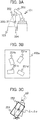
- FIGS. 3A, 3B and 3C are explanatory diagrams of recognition errors of an article caused by the robot 101 according to the embodiment of the present invention.
- FIG. 3A in the case where the storage box recognition sensor 204 recognizes the storage box 103 conveyed to the working area, the article recognition sensor 202 photographs the direction of the storage box 103.
- FIG. 3B is a plan view for showing an example of arrangement of four articles 251 (namely, articles 251a to 251d) stored in a storage box 103a that is one of the storage boxes 103.
- FIG. 3C shows an example of a difference between the true position of the article 251 shown by a rectangle of the thick solid line and a recognition result 252 shown by a rectangle of the thick dotted line.
- recognition errors include ⁇ x and ⁇ y that are differences between the coordinate values of the center position of the article 251 and the coordinate values of the center position of the recognition result 252 and ⁇ that is a difference between the direction of the center line of the article 251 and the direction of the center line of the recognition result 252.
- the former is also described as a positional error, and the latter is also described as a postural error.
- FIGS. 4A and 4B are explanatory diagrams of recognition errors of an article when the robot 101 according to the embodiment of the present invention grips the article.
- FIG. 4A is a plan view for showing an example of a relation among the fingers 209, the actual position of the article 251, and the recognition result 252 of the article 251 in the case where the article 251 is gripped using the finger-type hand 203a.
- the positional errors ⁇ x and ⁇ y and the postural error ⁇ as similar to FIG. 3C are present between the article 251 and the recognition result 252 in FIG. 4A .
- the robot 101 determines the grip position by the finger-type hand 203a on the basis of the recognition result 252.
- the robot 101 sandwiches the centers of the long sides on the both sides of the recognition result 252 from the directions perpendicular to the long sides using the fingers 209a and 209b.
- the posture of the article 251 is changed, and the direction of the center line of the article 251 matches the direction of the center line of the recognition result 252. Namely, the postural error is accordingly resolved.
- the position of the article 251 is changed to the direction (the direction perpendicular to the long sides of the recognition result 252 in the example of FIG. 4A , and the direction is also described as the open/close direction of the fingers 209 below) where the fingers 209a and 209b move when sandwiching the article 251 by the grip, and an error in the direction perpendicular thereto remains.
- ⁇ d represents the amount of the error remaining in the direction perpendicular to the open/close direction of the fingers 209.
- FIG. 4B is a plan view for showing an example of a relation among the suction pad 210a, the article 251, and the recognition result 252 of the article 251 in the case where the article 251 is gripped using the suction hand 203b.
- the robot 101 determines the center position of the recognition result 252 as the grip position by the suction hand 203b.
- the grip position is shifted from the actual center of the article 251 by only ⁇ x and ⁇ y.
- the posture of the article 251 is not changed.
- the positional errors ⁇ x and ⁇ y and the postural error ⁇ still remain.
- FIGS. 5A, 5B, 5C and 5D are explanatory diagrams of gripping of an article by the finger-type hand 203a according to the embodiment of the present invention.
- FIG. 5A is a perspective view of the finger-type hand 203a sandwiching and gripping an article 251i using the fingers 209a and 209b.
- FIG. 5B is a side view obtained by viewing the finger-type hand 203a and the article 251i of FIG. 5A from the y direction (namely, the direction parallel to short sides of the article 251i in a horizontal surface) .
- FIG. 5C is a side view obtained by viewing the finger-type hand 203a and the article 251i of FIG. 5A from the x direction (namely, the direction parallel to long sides of the article 251i in a horizontal surface).
- FIG. 5D is a plan view obtained by viewing the finger-type hand 203a and the article 251i of FIG. 5A from the z direction (namely, the upper direction).
- the distance W from an end of the open/close direction of the finger 209 to an inner end of the finger 209 when gripping the article 251i in the finger-type hand 203a indicates the size of a space that needs to be secured between an inner wall surface of the sorting box 105 and a side surface of the article 251i in order to insert the finger 209.
- the distance W is calculated on the basis of information of the preliminarily-retained size of the finger-type hand 203a and information of the size of the article 251i (see FIG. 28 ).
- the maximum error AD of the grip position of the article 251i is calculated by Equation (2).
- ⁇ D ⁇ P ⁇ cos ⁇ + sin ⁇
- ⁇ D represents the maximum error of the grip position of the article 251i
- ⁇ P denotes an article position recognition maximum error
- ⁇ denotes an article posture recognition maximum error.
- the ideal height L of the tip end of the finger 209 when gripping the article 251i is calculated by Equation (3). It should be noted that the height of the tip end of the finger 209 in this case means a distance from the bottom surface of the article 251i to the tip end of the finger 209. In addition, “ideal” means "target”.
- L H ⁇ Lmin + ⁇ Q
- L represents the ideal height of the tip end of the finger 209 when gripping the article 251i
- H represents the height of the article 251i
- ⁇ Q represents an article height recognition maximum error
- Lmin represents a minimum grip amount (namely, the minimum value of a distance from the upper surface of the article 251i to the tip end of the finger 209 that needs to be secured to stably grip the article 251i).
- FIG. 6 is an explanatory diagram of the ideal installation position of an article that is initially stored into the sorting box 105 by the finger-type hand 203a according to the embodiment of the present invention.
- FIG. 6 is a plan view for showing the ideal installation position of the article 251i in the sorting box 105 when the article 251i is initially stored using the finger-type hand 203a into the sorting box 105 in which no article is stored yet.
- the ideal installation position is a position where a distance between a short side of the article 251i and a wall surface of the sorting box 105 parallel to the short side is ⁇ A+e+ ⁇ D and a distance between a long side of the article 251i and a wall surface of the sorting box 105 parallel to the long side is ⁇ B+W+e.
- ⁇ A represents the maximum error of the installation position of the article 251i in the x direction caused by the recognition error of the sorting box 105
- ⁇ B represents the maximum error of the installation position of the article 251i in the y direction caused by the recognition error of the sorting box 105
- "e" represents a margin (a predetermined value equal to or larger than 0).
- ⁇ A and ⁇ B are calculated by Equation (4) and Equation (5), respectively.
- ⁇ A ⁇ X + a / 2 ⁇ 1 ⁇ cos ⁇ + b / 2 ⁇ sin ⁇
- ⁇ B ⁇ Y + b / 2 ⁇ 1 ⁇ cos ⁇ + a / 2 ⁇ sin ⁇
- a represents the length of the sorting box 105 (namely, the length of the sorting box 105 in the direction parallel to the surface of the finger 209 contact with the article 251i)
- b represents the width of the sorting box 105 (namely, the length of the sorting box 105 in the open/close direction of the finger 209)
- ⁇ X represents the recognition maximum error of the position of the sorting box 105 in the x direction
- ⁇ Y represents the recognition maximum error of the position of the sorting box 105 in the y direction
- ⁇ represents the recognition maximum error of the posture of the sorting box 105.
- ⁇ A and ⁇ B are calculated in the case where the position of the sorting box 105 is recognized using the sorting box recognition sensor 205.
- the positional error of the sorting box 105 is negligibly small in such a case that, for example, the sorting box conveyor 104 is provided with a mechanism of always stopping the sorting box 105 at a fixed position, ⁇ A and ⁇ B can be 0.
- the finger-type hand 203a grips the article 251i to be inserted into the sorting box 105 from an opening portion at an upper end of the sorting box 105 while being moved into the direction of the bottom surface, it is necessary to secure a distance of ⁇ A+e+ ⁇ D between a wall surface parallel to the y direction and the article 251i.
- the article 251i may be thereafter moved in the -x direction by only the margin e (namely, the article 251i is brought closer to the wall surface direction by only the margin e) to be installed on the bottom surface. In this case, a distance between a wall surface parallel to the y direction and the article 251i is ⁇ A+ ⁇ D.
- FIG. 7 is an explanatory diagram of the height of the tip end of the finger 209 at the time of shift movement of an article by the finger-type hand 203a according to the embodiment of the present invention.
- FIG. 7 explains the height from the bottom surface of the sorting box 105 to the tip end of the finger 209 in such a case that when the article 251i is stored using the finger-type hand 203a into the sorting box 105 in which an article 251p is already stored, the article 251i is horizontally moved to the direction of the article 251p after the article 251i is moved from an opening portion of the sorting box 105 to near the bottom surface.
- movement including at least components in the vertical direction in such a case that the article 251 is moved from an opening portion of the sorting box 105 to near the bottom surface is also described as "insertion”
- movement including at least components in the horizontal direction in such a case that the article 251 having reached near the bottom surface is brought closer to a wall surface of the sorting box 105 or the direction of another article 251 already installed on the bottom surface is also described as "shift movement”.
- shift movement movement including at least components in the vertical direction in such a case that the article 251 is moved from an opening portion of the sorting box 105 to near the bottom surface
- shift movement including at least components in the horizontal direction in such a case that the article 251 having reached near the bottom surface is brought closer to a wall surface of the sorting box 105 or the direction of another article 251 already installed on the bottom surface is also described as "shift movement”.
- the moving direction at the time of insertion of the article 251 is different from the moving direction at the time of shift movement.
- the sorting box 105 is not illustrated
- the minimum height (namely, the minimum distance from the bottom surface of the sorting box 105) ⁇ min of the tip end of the finger 209 at the time of shift movement of the article 251i is calculated by Equation (6) .
- ⁇ min L + ⁇ Q + e
- ⁇ min represents the minimum height of the tip end of the finger 209 at the time of shift movement of the article 251i.
- the article 251p When pushing around an upper surface of the article 251p at the time of shift movement of the article 251i, the article 251p falls without being slid on the floor surface in some cases. Therefore, the article 251i is desirably shifted and moved at a position as low as possible. However, if the position is too low, the finger 209 of the hand 203a abuts on the article 251p in some cases.
- the ideal height namely, the ideal distance from the bottom surface of the sorting box 105
- ⁇ of the tip end of the finger 209 at the time of shift movement of the article 251i is calculated by Equation (8) in the case where Equation (7) is established, and is calculated by Equation (10) in the case where Equation (9) is established.
- ⁇ represents the ideal height of the tip end of the finger 209 at the time of shift movement of the article 251i
- Hp represents the height of the adjacent article 251p that is already installed.
- the height of the finger-type hand 203a can be controlled so that the height of the bottom surface of the article 251i is higher than the height of the bottom surface of the article 251p and the height of the bottom surface of the article 251i is lower than the height of the upper surface of the article 251p.
- the shift movement of the article 251i at a low position can be realized by the above-described control while satisfying the conditions where the finger 209 of the finger-type hand 203a does not hit the article 251p.
- FIGS. 8 are explanatory diagrams of an ideal installation position in the case where an article is additionally installed using the finger-type hand 203a according to the embodiment of the present invention.
- an article 251m is newly stored in a state where articles 251i, 251j, and 251k are already stored.
- the articles 251i and 251j are installed adjacent to each other in the y direction, and the articles 251i and 251k are installed adjacent to each other in the x direction. All the articles are installed so that the long sides thereof are parallel to the x direction.
- the position of the article 251m to be installed is a position where the side surface of the article 251m on the short-side side comes into contact with the article 251j and the side surface thereof on the long-side side comes into contact with the article 251k.
- the robot 101 inserts the article 251m using the finger-type hand 203a into a position apart from the side surface of the article 251j adjacent to the direction (the x direction in the example of FIGS. 8 ) parallel to the surface of the finger 209 by only 2 ⁇ D+e and apart from the side surface of the article 251k adjacent to the open/close direction (the y direction in the example of FIGS. 8 ) of the finger 209 by only e.
- a plan view of the arrangement of each article 251 at this time is shown in FIG. 8A
- a side view viewed from the x direction is shown in FIG. 8B .
- the article 251m is still gripped by the finger-type hand 203a at this time, and does not come into contact with the bottom surface of the sorting box 105.
- the robot 101 moves the article 251m in the x direction by only -(2 ⁇ D+e) and in the y direction by only -e. Accordingly, the side surface of the article 251m on the short-side side comes into contact with the article 251j, and the side surface thereof on the long-side side comes into contact with the article 251k.
- a plan view of the arrangement of each article 251 at this time is shown in FIG. 8C , and a side view viewed from the x direction is shown in FIG. 8D .
- FIG. 8E A plan view of the arrangement of each article 251 at this time is shown in FIG. 8E , and a side view viewed from the x direction is shown in FIG. 8F .
- the robot 101 may move the article 251m up to the position shown in each of FIG. 8C and FIG. 8D , and then may further move the same in the y direction by only - (W+e) . Accordingly, the article 251k is moved by being pushed by the article 251m, and a distance between the article 251k and the wall surface facing the side surface thereof on the long-side side is only ⁇ B. Even when the article 251j is installed after the article 251i is installed, the articles may be similarly moved. Accordingly, a distance between the wall surface and the article 251 becomes small, and further the use efficiency of the volume of the sorting box 105 is improved.
- FIGS. 9A, 9B, 9C and 9D are explanatory diagrams of an actual installation position including the maximum error in the case where an article is additionally installed using the finger-type hand 203a according to the embodiment of the present invention.
- the articles 251i and 251k are placed at the ideal positions, but the article 251j is placed at a position shifted from the ideal position in the x direction by only + ⁇ D.
- FIG. 9A is a side view for showing a positional relation among the wall surface, the article 251j, and the article 251m shown in FIG. 9A .
- the article 251m is inserted into the position shifted in the x direction by only + (2 ⁇ D+e) from the position where the article 251m is to be finally installed, and thus a space corresponding to the margin e is secured between the articles 251j and 251m even in the case where the above-described error is present. Accordingly, even in the case where the maximum error that can be assumed occurs, the article 251m can be inserted into the sorting box 105 without being damaged by contact with the article 251j.
- the robot 101 moves the article 251m in the x direction by - (2 ⁇ D+e) while gripping the same using the finger-type hand 203a. Then, the article 251m comes into contact with the article 251j when the article 251m is moved by only the margin -e. Further, when the robot 101 moves the article 251m so as to push the article 251j, both of the articles 251j and 251m are installed at positions shifted from the ideal positions in the x direction by only - ⁇ D when a movement of -(2 ⁇ D+e) is competed.
- a distance between the ideal position of the article 251j and the wall surface (the dashed line of FIG. 9 ) on the basis of the recognition result of the sorting box 105 is originally ⁇ A+e+ ⁇ D. Therefore, even when a recognition error of ⁇ A actually occurs, a space corresponding to the margin e is secured between the actual wall surface (the solid line of FIG. 9 ) and the article 251j (see FIG. 9C and FIG. 9D ).
- the article 251j precisely comes into contact with the wall surface.
- FIG. 10A, 10B, 10C and 10D are explanatory diagrams of gripping of an article by the suction hand 203b according to the embodiment of the present invention.
- FIG. 10A is a perspective view of the suction hand 203b gripping the article 251i while being sucked by the suction pad 210a.
- FIG. 10B is a side view obtained by viewing the suction hand 203b and the article 251i of FIG. 10A from the y direction (namely, the direction parallel to short sides of the article 251i in a horizontal surface).
- FIG. 10C is a side view obtained by viewing the suction hand 203b and the article 251i of FIG. 10A from the x direction (namely, the direction parallel to long sides of the article 251i in a horizontal surface).
- FIG. 10D is a plan view obtained by viewing the suction hand 203b and the article 251i of FIG. 10A from the z direction (namely, the upper direction).
- a vacuum pressure is measured by driving the arm 201 to move the suction pad 210a from the above of the article 251i to the lower direction. Then, when detecting the suction of the article 251i on the basis of the measured vacuum pressure, the arm 201 is immediately stopped. Accordingly, the article 251i can be correctly sucked even when an error occurs in recognition of the height of the article 251i.
- the article position recognition maximum error ⁇ P and the article posture recognition maximum error ⁇ are the same as in the case of the finger-type hand 203a.
- FIG. 11 is an explanatory diagram of the ideal installation position of an article that is initially stored into the sorting box 105 by the suction hand 203b according to the embodiment of the present invention.
- FIG. 11 is a plan view for showing the ideal installation position of the article 251i in the sorting box 105 when the article 251i is initially stored using the suction hand 203b into the sorting box 105 in which no article is stored yet.
- the ideal installation position is a position where a distance between a short side of the article 251i and a wall surface of the sorting box 105 parallel to the short side is ⁇ A+e+ ⁇ P+ ⁇ U and a distance between a long side of the article 251i and a wall surface of the sorting box 105 parallel to the long side is ⁇ B+e+ ⁇ P+ ⁇ V.
- ⁇ A represents the maximum error of the installation position of the article 251i in the x direction caused by the recognition error of the sorting box 105
- ⁇ B represents the maximum error of the installation position of the article 251i in the y direction caused by the recognition error of the sorting box 105
- ⁇ U represents the maximum error of the article installation position in the x direction due to the article posture recognition error
- ⁇ V represents the maximum error of the article installation position in the y direction due to the article posture recognition error
- "e" represents a margin.
- ⁇ A and ⁇ B are calculated by Equation (4) and Equation (5), respectively. It should be noted that the length a of the sorting box 105 is the length of the sorting box 105 in the x direction, and the width b of the sorting box 105 is the length of the sorting box 105 in the y direction.
- ⁇ U and ⁇ V are calculated by Equation (11) and Equation (12), respectively.
- u represents the length (the x direction, the long side) of the article 251i
- v represents the width (the y direction, the short side) of the article 251i.
- ⁇ A and ⁇ B are calculated in the case where the position of the sorting box 105 is recognized using the sorting box recognition sensor 205. As similar to the case of Fig. 6 , in the case where the positional error of the sorting box 105 is negligibly small, ⁇ A and ⁇ B can be 0.
- the suction hand 203b grips the article 251i to be inserted into the sorting box 105 from an opening portion at an upper end of the sorting box 105 and moves the same to near the bottom surface of the sorting box 105, it is necessary to provide the margin e in each of the x direction and the y direction. However, the suction hand 203b may thereafter move the article 251i in the -x direction and the -y direction by only the margin e to shorten a distance between the article 251i and the wall surface, and then may install the same on the bottom surface.
- the article 251i may be thereafter moved in the -x direction by only the margin e (namely, the article 251i is brought closer to the wall surface direction by only the margin e) to be installed on the bottom surface.
- a distance between a short side of the article 251i and a wall surface of the sorting box 105 parallel to the short side is ⁇ A+ ⁇ P+ ⁇ U.
- a distance between a long side of the article 251i and a wall surface of the sorting box 105 parallel to the long side is ⁇ B+ ⁇ P+ ⁇ V.
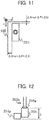
- FIG. 12 is an explanatory diagram of the height of the tip end of the suction pad 210a at the time of shift movement of an article by the suction hand 203b according to the embodiment of the present invention.
- FIG. 12 explains the height from the bottom surface of the sorting box 105 to the tip end of the suction pad 210a in such a case that when the article 251i is stored using the suction hand 203b into the sorting box 105 in which the article 251p is already stored, the article 251i is horizontally moved to the direction of the article 251p after the article 251i is moved from an opening portion of the sorting box 105 to near the bottom surface. The movement in the horizontal direction is also described as shift movement. It should be noted that the sorting box 105 is not illustrated in FIG. 12 for convenience of explanation.
- ⁇ represents the height of the tip end of the suction pad 210a at the time of shift movement of the article 251i
- H represents the height of the article 251i.
- the height of the suction hand 203b can be controlled so that the height of the bottom surface of the article 251i is higher than the height of the bottom surface of the article 251p and the height of the bottom surface of the article 251i is lower than the height of the upper surface of the article 251p. Further, the shift movement of the article 251i at a lower position can be realized.
- FIGS. 13A, 13B, 13C, 13D, 13E and 13F are explanatory diagrams of an ideal installation position in the case where an article is additionally installed using the suction hand 203b according to the embodiment of the present invention.
- the article 251m is newly stored in a state where the articles 251i, 251j, and 251k are already stored as similar to the example of FIGS. 8A, 8B, 8C, 8D, 8E and 8F .
- the robot 101 inserts the article 251m using the suction hand 203b into a position apart from the side surface of the article 251j adjacent to the x direction by only 2( ⁇ P+ ⁇ U)+e and apart from the side surface of the article 251k adjacent to the y direction by only 2( ⁇ P+ ⁇ V)+e.
- a plan view of the arrangement of each article 251 at this time is shown in FIG. 13A
- a side view viewed from the x direction is shown in FIG. 13B .
- the article 251m is still gripped by the suction hand 203b at this time, and does not come into contact with the bottom surface of the sorting box 105.
- the robot 101 moves the article 251m in the -x direction by only 2( ⁇ P+ ⁇ U)+e and in the -y direction by only 2( ⁇ P+ ⁇ V)+e. Accordingly, the side surface of the article 251m on the short-side side comes into contact with the article 251j, and the side surface thereof on the long-side side comes into contact with the article 251k.
- a plan view of the arrangement of each article 251 at this time is shown in FIG. 13C
- a side view viewed from the x direction is shown in FIG. 13D .
- FIG. 13E A plan view of the arrangement of each article 251 at this time is shown in FIG. 13E , and a side view viewed from the x direction is shown in FIG. 13F .
- FIG. 14 is an explanatory diagram of a relation between the ideal position of an article and an assumed region in consideration of the maximum error in the case where the suction hand 203b according to the embodiment of the present invention is used.
- FIG. 14 is a plan view for showing the installation position of the article 251 and a region where the article 251 is possibly installed.
- a frame 1401 of the thick solid line shows the ideal position of the article 251. The range of the frame is also described as the region of the ideal position.
- a frame 1402 of the thin solid line shows an example of the position of the article 251 in the case where the positional error is zero and the postural error is maximum.
- a frame 1403 of the thin dotted line shows the assumed region where the article 251 is actually installed in consideration of the postural maximum error and without consideration of the positional error (namely, the positional error is zero).
- the postural error is a value from zero to the maximum value and the positional error is zero
- the article 251 possibly exists at any position in the frame 1403 of the thin dotted line, but does not exist on the outside thereof.
- a frame 1404 of the thick dotted line shows the assumed region where the article 251 is actually installed in consideration of the postural maximum error and the positional maximum error.
- the article 251 possibly exists at any position in the frame 1404 of the thick dotted line, but does not exist on the outside thereof.
- FIGS. 15A, 15B and 15C are first explanatory diagrams of an actual installation position including the maximum error in the y direction in the case where an article is additionally installed using the suction hand 203b according to the embodiment of the present invention.
- the article 251i is already stored in the sorting box 105.
- the postural error is maximum, and the positional error in the +y direction is maximum. Therefore, the article 251i is installed in such a manner that an end in the +y direction is shifted from the ideal position to the +y direction by only ⁇ P+ ⁇ V.
- the postural error is maximum, and the positional error in the -y direction is maximum.
- the suction position (the position of the double circle in each of FIGS. 15A, 15B and 15C ) by the suction pad 210a is shifted from the ideal position to the y direction by only + ⁇ P. Therefore, the insertion position of the article 251j to the sorting box 105 is positioned in such a manner that an end in the -y direction is shifted from the ideal position to the -y direction by only ⁇ P+ ⁇ V. Namely, the article 251j is inserted into a position where a distance between the article 251j and the actual position of the article 251i is minimized.
- the article 251j is inserted so that a space of 2 ( ⁇ P+ ⁇ V) +e is secured between the region of the ideal position of the article 251j and the region of the ideal position of the article 251i is secured. Namely, each of the assumed regions where the postural maximum errors and the positional maximum errors of the article 251i and the article 251j are considered is separated in the y direction by only the margin e. Therefore, even when the above-described error is present, the contact of the article 251j with the article 251i is avoided.
- the postural error can be virtually regarded as zero by assuming that the posture of the article 251i is modified by being sandwiched between the wall surface of the sorting box 105 and the article 251j ( FIG. 15B ). Then, a margin of ⁇ V is created on each side surface in the y direction of the article 251i whose postural error is virtually zero.
- the robot 101 moves the suction hand 203b to move the article 251j in the -y direction by only 2( ⁇ P+ ⁇ V)+e.
- the article 251i is pushed by the article 251j to be moved in the -y direction.
- a space corresponding to the margin e remains between the article 251i and the wall surface parallel to the x direction ( FIG. 15C ). As a result, the article 251i is not crushed.
- the positional error of the article 251j is ⁇ P in the -y direction with respect to the ideal position. Since the postural error is additionally present, the actual article 251j occupies a region larger than that occupied by the article 251j at the ideal position by only 2 ⁇ V in the y direction.
- FIGS. 16A, 16B and 16C are second explanatory diagrams of an actual installation position including the maximum error in the y direction in the case where an article is additionally installed using the suction hand 203b according to the embodiment of the present invention.
- FIGS. 16A, 16B and 16C show states continued from FIGS. 15A, 15B and 15C .
- FIG. 16A shows a state in which after the articles 251i and 251j are installed as shown in FIG. 15C , an article 251n is newly inserted into a position adjacent to the article 251j on the +y side.
- the article 251n has the maximum postural error in the direction opposite to the article 251j, and further the suction position by the suction pad 210a is shifted from the ideal position by only + ⁇ P in the y direction. As a result, the actual position of the article 251n is located closest to the article 251j in the assumed error range.
- the article 251n is inserted so that a space of 2( ⁇ P+ ⁇ V)+e is secured between the region of the ideal position of the article 251n and the region of the ideal position of the article 251j.
- each of the assumed regions where the postural maximum errors and the positional maximum errors of the article 251j and the article 251n are considered is separated in the y direction by the only e+ ⁇ P. Therefore, even when the above-described error is present, the contact of the article 251n with the article 251j is avoided.
- the postural error can be virtually regarded as zero by assuming that the posture of the article 251j is modified by being sandwiched between the article 251i and the article 251n.
- the position is located apart from the ideal position in the y direction by - ⁇ P ( FIG. 16B ).
- the robot 101 moves the suction hand 203b to move the article 251n in the -y direction by only 2( ⁇ P+ ⁇ V)+e.
- the article 251j is pushed by the article 251n, and the postural error thereof is modified.
- the article 251j and the article 251i precisely come into contact with each other, and both of the article 251j and the article 251i are not crushed ( FIG. 16C ).
- the positional error of the article 251n is ⁇ P in the -y direction with respect to the ideal position. Since the postural error is additionally present, the actual article 251n occupies a region larger than that occupied by the article 251n at the ideal position by only 2 ⁇ V in the y direction.
- FIGS. 15 and FIGS. 16 explain operations of reducing the extra space in the y direction and modifying the posture of the article adjacent in the y direction by moving the newly-inserted article 251 in the y direction.
- the extra space between the newly-inserted article 251 and the article 251 adjacent thereto in the x direction can be reduced and the posture of the adjacent article 251 can be modified.
- the operations in the x direction and the operations in the y direction can be simultaneously carried out. The operations will be described with reference to FIGS. 17A and 17B .
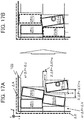
- FIGS. 17A and 17B are explanatory diagrams of an actual installation position including the maximum error in the case where an article is additionally installed using the suction hand 203b according to the embodiment of the present invention.
- both of the article 251j installed adjacent to the article 251i in the +y direction and the article 251k installed adjacent to the article 251i in the +x direction have the maximum postural errors and the maximum positional errors in the example.
- each of the article 251j and the article 251k is installed in such a manner that an end in the +x direction is shifted from the ideal position in the +x direction by only ⁇ P+ ⁇ U and an end in the +y direction is shifted from the ideal position in the +y direction by only ⁇ P+ ⁇ V.
- the article 251m that is adjacent to the article 251j in the x direction and is newly inserted into a target position adjacent to the article 251k in the y direction has the maximum postural error in the direction opposite to the article 251j and the article 251k. Further, the grip position of the article 251m by the suction pad 210a is shifted from the ideal position in the x direction and the y direction by only + ⁇ P.
- the position of the article 251m to be inserted is shifted from the ideal position in the x direction and the y direction by only - ⁇ P. Namely, the actual position into which the article 251m is inserted is located closest to the article 251j and the article 251k in the assumed error range.
- the article 251m is inserted so that a space of 2( ⁇ P+AU)+e is secured between the region of the ideal position of the article 251m and the region of the ideal position of the article 251j and a space of 2( ⁇ P+ ⁇ V)+e is secured between the region of the ideal position of the article 251m and the region of the ideal position of the article 251k.
- each of the assumed regions where the postural maximum errors and the positional maximum errors of the article 251m and the article 251j are considered is separated in the x direction and the y direction by only the margin e. Therefore, even when the above-described error is present, the contact of the article 251m with the article 251j and the article 251k is avoided ( FIG. 17A ).
- the robot 101 moves the suction hand 203b to move the article 251m in the -x direction by only 2( ⁇ P+ ⁇ U)+e. Then, the posture maximum error assumed regions (the thick dotted lines of FIG. 17A ) of the article 251j and the article 251m come into contact with each other when the article 251m is moved by only the margin e.
- each of the article 251j and the article 251m is installed at a position shifted from the ideal position by only ⁇ P in the -x direction.
- the postural error of the article 251j is accordingly modified (the article 251j of FIG. 17B ).
- the robot 101 moves the suction hand 203b to move the article 251m in the -y direction by only 2( ⁇ P+ ⁇ V)+e. Then, the posture maximum error assumed regions (the thick dotted lines of FIG. 17A ) of the article 251k and the article 251m come into contact with each other when the article 251m is moved by only the margin e.
- each of the article 251k and the article 251m is installed at a position shifted from the ideal position by only ⁇ P in the -y direction.
- the postural error of the article 251k is accordingly modified (the article 251k of FIG. 17B ).
- FIGS. 18A, 18B, 18C, 18D, 18E and 18F storage of an article by the robot 101 having the double suction hand 203c will be described with reference to FIGS. 18A, 18B, 18C, 18D, 18E and 18F .
- FIGS. 18A, 18B, 18C, 18D, 18E and 18F are explanatory diagrams of gripping of an article by the double suction hand 203c according to the embodiment of the present invention.
- FIG. 18A is a perspective view of the double suction hand 203c gripping articles 251g and 251h while being sucked by the suction pads 210b and 210c, respectively.
- FIG. 18B is a plan view for showing an example of a relation among the suction pad 210b, the article 251g, and a recognition result 252g of the article 251g.
- FIG. 18C is a plan view for showing an example of a relation among the suction pad 210c, the article 251h, and a recognition result 252h of the article 251h.
- the positional errors ⁇ x and ⁇ y and the postural error ⁇ occur.
- the postural error of the article 251g is described as ⁇ g
- the postural error of the article 251h is described as ⁇ h.
- FIG. 18D is a plan view of the articles 251g and 251h gripped by the suction pads 210b and 210c, respectively, at the ideal positions with the ideal postures (namely, in a state where neither positional errors nor postural errors occur) .
- the centers of the articles 251g and 251h are sucked and gripped by the suction pads 210b and 210c, respectively, and these postures match those recognized by the robot 101.
- FIG. 18E and FIG. 18F are plan views each explaining procedures of gripping two articles 251g and 251h using the double suction hand 203c.
- the double suction hand 203c grips no articles, and each of the articles 251g and 251h is placed at an arbitrary position in the storage box 103.
- the robot 101 sucks and grips the article 251g using the suction pad 210b. At this time, as shown in FIG. 18B , there are errors in the actual suction position and posture of the article 251g with respect to the ideal position and the ideal posture. Thereafter, the robot 101 brings the double suction hand 203c close to the article 251h.
- the robot 101 matches the suction pad 210c with the suction position (for example, the center of the recognition result 252h) of the recognition result 252h of the article 251h, but further moves the suction pad 210c in the -y direction by only 2( ⁇ P+ ⁇ V)+e.
- the article 251h is pushed by the article 251g in the -y direction, and the posture thereof becomes substantially the same as that of the article 251g ( FIG. 18E ).
- “Substantially the same” does not mean “exactly the same”, and is a concept including a state in which the surfaces of the sucked articles 251g and 251h facing each other come into contact with each other or follow each other.
- the robot 101 lowers the double suction hand 203c so that the tip end of the suction pad 210c has a height equal to that of the upper surface of the article 251h, and sucks and grips the article 251h.
- suction pads 210b and 210c are modified examples of second and third processes executed after a process (first process) of arranging a first article in the sorting box 105 is executed.
- the robot 101 takes out the article 251g and the article 251h from the storage box 103, and moves the same to near the first article in the sorting box 105.
- the robot 101 sucks the upper surface of the article 251g in the storage box 103 using a first suction pad 210b.
- the article 251g is placed adjacent to the article 251h while providing a space.
- the article 251g changes the posture of the article 251h. At this time, the postures of the articles 251g and 251h become substantially the same.
- the robot 101 comes close to the first article in the sorting box 105 while gripping the two articles 251g and 251h, and changes the postures and positions of the other articles after the articles come into contact with each other. Thereafter, the robot 101 that has moved the other articles to predetermined positions or has changed the same into predetermined postures arranges the two articles 251g and 251h on the bottom surface of the sorting box 105 by releasing the two suction pads 210b and 210c, and the two articles can be stored into the box. Accordingly, a gap between the first article already arranged in the sorting box 105 and the article 251g or the article 251h can be reduced. It should be noted that the number of first articles may be two or more.
- the article in contact with the first article is released first, and then the article not in contact with the first article is released.
- the posture is hardly deviated. Accordingly, a gap between the articles can further reduced, and thus the housing efficiency in the box can be improved.
- the embodiment can be carried out even in a state where no article has been stored in the sorting box 105. Namely, the embodiment can be carried out from the second process. In this case, since a distance (space) between the articles 251g and 251h can be reduced, two articles can be stored in the sorting box 105 with space saving, and the housing efficiency in the box can be improved.
- the embodiment can also contribute to improvement in the housing efficiency in the sorting box 105.
- FIG. 19 is an explanatory diagram of a hardware configuration of the robot system according to the embodiment of the present invention.
- the entire management computer 109, the host system 110, the instruction terminal 107, the storage box conveyor 102, the sorting box conveyor 104, the automatic rack 108, and the robot 101 are connected to each other via a network 301.
- the network 301 may be a wired network, a wireless network, or a combination thereof as long as data communications can be performed via the network 301.
- the entire management computer 109 is a computer having a central control device 311, a main storage device 312, a communication device 314, an input device 315, an output device 316, and an auxiliary storage device 313.
- the central control device 311 is a processor that executes various processes by executing programs stored in the main storage device 312.
- the input device 315 is a device that accepts an input of information from a user of the entire management computer 109, and may be, for example, a keyboard, a mouse, or the like.
- the output device 316 is a device that outputs information to a user of the entire management computer 109, and may be, for example, a display device displaying characters, images, or the like.
- the communication device 314 is a device that communicates with each equipment, via the network 301, such as the host system 110 and the robot 101 connected to the network 301.
- the main storage device 312 is, for example, a storage device such as a DRAM (Dynamic Random Access Memory), and holds a program and the like executed by the central control device 311.
- the main storage device 312 shown in FIG. 19 holds an order processing unit 331. This is a program executed by the central control device 311.
- a process executed by the order processing unit 331 in the following description is actually executed by the central control device 311 in accordance with the program held by the main storage device 312. The process executed in accordance with the program will be described later in detail.
- the auxiliary storage device 313 is, for example, a storage device such as a hard disk drive or a flash memory, and holds information and the like necessary for a process executed by the central control device 311.
- the auxiliary storage device 313 shown in FIG. 19 holds warehouse state management information 341, warehouse definition information 342, order information 343, and work plan information 344. These pieces of information will be described later in detail (see FIG. 20 to FIG. 28 ). It should be noted that at least a part of these pieces of information may be copied to the main storage device 312 if needed, and may be referred to by the central control device 311.
- programs executed by the central control device 311 may be stored in the auxiliary storage device 313, and at least a part of the programs may be copied to the main storage device 312 if needed.
- the instruction terminal 107 is a computer having a central control device 391, a main storage device 392, an auxiliary storage device 393, a communication device 394, an input device 395, and an output device 396 that are mutually connected to each other.
- the central control device 391 is a processor that executes various processes by executing a program (not shown) stored in the main storage device 392.
- the input device 395 is a device that accepts an input of information from the worker 106, and may be, for example, a keyboard, a mouse, a touch sensor, or the like.
- the output device 396 is a device that outputs information to the worker 106, and may be, for example, a display device displaying characters, images, or the like.
- the input device 395 and the output device 396 may be integrated such as, for example, a so-called touch panel.
- the communication device 394 is a device that communicates with the entire management computer 109 via the network 301.
- the main storage device 392 is, for example, a storage device such as a DRAM, and holds a program and the like executed by the central control device 391.
- the auxiliary storage device 393 is, for example, a storage device such as a hard disk drive or a flash memory, and holds information and the like necessary for a process executed by the central control device 391.
- the host system 110 is a computer that receives an order from each delivery destination (for example, a store or the like that receives and sells articles stored in the warehouse), and generates order information to be transmitted to the entire management computer 109.
- a hardware configuration of the host system 110 may be the same as that of the entire management computer 109, and thus the illustration and explanation thereof will be omitted.
- the robot 101 has a central control device 351, a main storage device 352, an auxiliary storage device 353, and a communication device 354, in addition to the arm 201, the article recognition sensor 202, the hand 203, the storage box recognition sensor 204, and the sorting box recognition sensor 205.
- the central control device 351 is a processor that executes various processes by executing a program stored in the main storage device 352.
- the communication device 354 is a device that communicates with each equipment, via the network 301, such as the entire management computer 109 connected to the network 301.
- the main storage device 352 is, for example, a storage device such as a DRAM, and holds a program and the like executed by the central control device 351.
- the main storage device 352 shown in FIG. 19 holds a robot management unit 361, a mechanism control unit 362, a sensor control unit 363, a box recognition unit 364, an article recognition unit 365, and an operation plan unit 366. These are programs executed by the central control device 311.
- processes executed by the above-described units in the following description are actually executed by the central control device 311 controlling the arm 201, the article recognition sensor 202, the hand 203, the storage box recognition sensor 204, and the sorting box recognition sensor 205 if needed in accordance with the programs held by the main storage device 312.
- the auxiliary storage device 353 is, for example, a storage device such as a hard disk drive or a flash memory, and holds information and the like necessary for a process executed by the central control device 351.
- the auxiliary storage device 353 shown in FIG. 19 holds the warehouse definition information 342 and in-box article arrangement information 381.
- the warehouse definition information 342 is the same as that held by the entire management computer 109.
- the in-box article arrangement information 381 will be described later in detail (see FIG. 29 ). It should be noted that at least a part of these pieces of information may be copied to the main storage device 352 if needed, and may be referred to by the central control device 351.
- programs executed by the central control device 351 may be stored in the auxiliary storage device 353, and at least a part of the programs may be copied to the main storage device 352 if needed.
- the robot management unit 361 is a main program of the robot 101. Specifically, the robot management unit 361 receives work plan information from the entire management computer 109 using the communication device 354, and performs the work using each equipment and function.
- the work procedure (for example, a series of work flows such as recognition of the sorting box 105, recognition of the storage box 103, recognition of the article 251, taking out the article 251, and boxing the article 251) at the time is programmed.
- the robot management unit 361 When the above-described work is completed, the robot management unit 361 notifies the entire management computer 109 of work completion using the communication device 354. In addition, after performing operations such as taking out the article 251 from the storage box 103 and storage into the sorting box 105, the robot management unit 361 updates the in-box article arrangement information 381.
- the mechanism control unit 362 controls the arm 201 and the hand 203. Specifically, the mechanism control unit 362 receives time-series data of an arm posture and a hand state created by the operation plan unit 366, and accordingly operates the arm 201 and the hand 203.
- the sensor control unit 363 controls the article recognition sensor 202, the storage box recognition sensor 204, and the sorting box recognition sensor 205. For example, in the case where these sensors are cameras or distance image sensors, the sensor control unit 363 instructs these sensors to photograph, and receives data of images or distance images.
- the box recognition unit 364 processes the data obtained from the storage box recognition sensor 204 and the sorting box recognition sensor 205, and confirms the IDs (identification information) of the storage box 103 and the sorting box 105 to identify the positions and directions thereof.
- the identification is performed by reading, for example, characters or bar codes put on the boxes.
- the position postures are recognized by, for example, measuring the front surfaces of the boxes and collating with shape data of the boxes. For example, in the case where two-dimensional bar codes are put on the boxes and the put positions and directions are held as box recognition data, the identification can be also performed by measuring and reading the same.
- the article recognition unit 365 processes the data obtained from the article recognition sensor 202, and recognizes the position and direction of the article 251 put in the storage box 103.
- the position and direction of the article 251 can be recognized by holding a pattern of the surface of the article as article recognition data and searching the article recognition data for the pattern of a photographed image.
- the article recognition unit 365 may simultaneously recognize the articles 251 corresponding to the number thereof.
- the operation plan unit 366 plans operations of the arm 201 and the hand 203 at the time of work such as recognizing the article, taking out the article, and boxing the article (namely, storing into the box).
- the operation plan unit 366 preliminarily defines an arm posture with which the field of view of the article recognition sensor 202 approximately matches the entire storage box 103 as a posture at the time of recognition, and creates time-series data of the arm postures shifting from the current posture to the posture at the time of recognition.
- each joint angle of the arm 201 is linearly changed.
- the operation plan unit 366 selects an article 251 to be taken out from the arrangement of the articles 251 obtained by the article recognition unit 365, and calculates an arm posture at the time of gripping on the basis of a relative hand position and direction at the time of gripping.
- the operation plan unit 366 preliminarily defines arm postures before and after taking out the article, and creates time-series data of a series of arm postures and hand states in which the posture before taking out the article is changed to the posture at the time of gripping, the hand is put in a gripping state, and the posture at the time of gripping is changed to the posture after taking out the article.
- the operation plan unit 366 determines the ideal insertion position and installation position of the article 251 on the basis of the article 251 that has been taken out, the current article arrangement in the sorting box 105, and boxing error information. In addition, the operation plan unit 366 calculates arm postures at the time of insertion and installation on the basis of a relative hand position and direction at the time of gripping.
- the operation plan unit 366 preliminarily defines arm postures before and after boxing, and creates time-series data of a series of arm postures and hand states in which the posture before boxing is changed to the posture at the time of installation through the posture at the time of insertion, the hand is put in a release state, and the posture at the time of installation is changed to the posture after boxing.
- FIG. 20 is an explanatory diagram of the warehouse state management information 341 held by the entire management computer 109 according to the embodiment of the present invention.
- the warehouse state management information 341 is information for managing the state of the warehouse, for example, the states of each automatic rack 108 and each sorting box 105 in the warehouse, and includes the number of automatic rack compartments 401, compartment information 402, the number of sorting boxes 403, and sorting box information 404.
- the number of automatic rack compartments 401 is a total of compartments of the automatic rack 108 in the warehouse.
- the compartment information 402 is information indicating the state of each compartment.
- FIG. 20 shows compartment information A related to a compartment and compartment information B related to another compartment in the warehouse as the compartment information 402.
- the compartment information 402 for each of all the compartments of all the automatic racks 108 in the warehouse may be actually held.
- the compartment information 402 will be described later in detail (see FIG. 25 ).
- the number of sorting boxes 403 is a total of the sorting boxes 105 for sorting work.
- the sorting box information 404 is information indicating the state of each sorting box 105.
- FIG. 20 shows sorting box information C related to a sorting box 105 and sorting box information D related to another sorting box 105 in the warehouse as the sorting box information 404.
- the sorting box information 404 for each of all the sorting boxes 403 for sorting work may be actually held.
- the sorting box information 404 will be described later in detail (see FIG. 26 ).
- FIG. 21 is an explanatory diagram of the warehouse definition information 342 held by the entire management computer 109 and the robot 101 according to the embodiment of the present invention.
- the warehouse definition information 342 includes the number of article types 501, article type information 502, sorting box shape data 1302, sorting box recognition data 1303, a robot kinematic model 2102, and a robot grip error model 2103.
- the number of article types 501 is the number of types of articles stored in the warehouse.
- the article type information 502 is information related to the type of each article.
- FIG. 21 shows article type information G and article type information H as the article type information 502. These exemplify the article type information 502 related to two of all the types of articles stored inside the warehouse, and the article type information 502 related to all the types of articles stored inside the warehouse is actually held. The article type information 502 will be described later in detail (see FIG. 27 ).
- the sorting box shape data 1302 is information of the shape (for example, the dimension and the like of each part) of the sorting box 105.
- the sorting box recognition data 1303 may include information indicating the attached position and direction.
- the box recognition unit 364 can identify the position and posture of the sorting box 105 on the basis of a result of the reading, the sorting box recognition data 1303, and the sorting box shape data 1302.
- the robot kinematic model 2102 is information for associating the state of a joint such as the arm 201 of the robot 101 with the position of the tip end of the hand 203, and is referred to when the operation plan unit 366 plans an operation of the arm 201 to move the hand 203 to a desired position.
- the robot grip error model 2103 includes information such as the maximum value of an error assumed when the position and posture of an article are recognized by the robot 101.
- the robot grip error model 2103 will be described later in detail (see FIG. 28 ).
- FIG. 22 is an explanatory diagram of the order information 343 held by the entire management computer 109 according to the embodiment of the present invention.
- the order information 343 is information indicating an order of articles accepted from each delivery destination, namely, the types and number of articles to be delivered to each delivery destination.
- the order information 343 includes an order ID 601, delivery destination information 602, the number of ordered article types 603, an article type ID 604, and the number of article type orders 605.
- the sorting work in the working area for the robot 101 includes work in which the robot 101 takes out articles of ordered types corresponding to the number of orders in accordance with the order information 343 from the storage box 103, and stores the same into the sorting box 105 corresponding to the delivery destination that placed the orders.
- the order ID 601 is information discriminating each order. For example, information related to one order accepted from one delivery destination is discriminated by one order ID.
- FIG. 22 shows only information related to one order accepted from one delivery destination as an example. However, one or more orders may be accepted from a plurality of delivery destinations. As an example of a handling method in this case, the order information 343 may be created for each delivery destination, orders from the same delivery destination may be unified into one, and a unique order ID may be allocated to each order information 343.
- the delivery destination information 602 is information indicating the delivery destination that placed an order, namely, information indicating the delivery destination of an ordered article.
- the number of ordered article types 603 is the number of ordered articles, namely, the number of types of articles to be delivered to a delivery destination.
- the article type ID 604 and the number of article type orders 605 are the type of an ordered article and the number of articles of the ordered type, respectively. In the case where articles of plural types are ordered, a plurality of sets of the article type ID 604 and the number of article type orders 605 is included in the order information 343.
- FIG. 22 exemplifies a set of an article type M ID and the number of article type M orders and a set of an article type N ID and the number of article type N orders.
- the order information 343 may actually include a set of the article type ID 604 and the number of article type orders 605 related to an article of still another type.
- FIG. 23 is an explanatory diagram of the work plan information 344 held by the entire management computer 109 according to the embodiment of the present invention.
- the work plan information 344 is information related to a plan of sorting work to be carried out in the warehouse, and includes an order ID 701, the number of conveyed storage boxes 704, and individual work information 706.
- the order ID 701 is identification information of an order as a target of a work plan.
- the number of conveyed storage boxes 704 is the number of storage boxes 103 conveyed in the work plan.
- the individual work information 706 is information related to work for each storage box 103.
- FIG. 23 exemplifies individual work information Q and individual work information R as the individual work information 706.
- the individual work information 706 is actually held for each of all the storage boxes 103 for which work needs to be performed.
- the individual work information 706 will be described later in detail (see FIG. 24 ).
- FIG. 24 is an explanatory diagram of the individual work information 706 held by the entire management computer 109 according to the embodiment of the present invention.
- the individual work information 706 is information related to work for each storage box 103, and includes a storage box holding compartment ID 801, an article type ID 803, and the number of article type orders 804.
- the storage box holding compartment ID 801 is information for identifying a compartment of the automatic rack 108 holding the storage box 103 for work.
- the article type ID 803 is information for identifying the type of an ordered article.
- the number of article type orders 804 indicates the number of ordered articles.
- FIG. 25 is an explanatory diagram of the compartment information 402 held by the entire management computer 109 according to the embodiment of the present invention.
- the compartment information 402 is information indicating the state of each compartment, and includes a compartment ID 901, the number of storage box conveyance reservations 902, a held article type ID 903, and the number of held articles 904.
- the compartment ID 901 is information for identifying each compartment.
- the number of storage box conveyance reservations 902 indicates whether or not a reservation of conveying the storage box 103 held in each compartment to the working area for sorting work has been made, and the number of reservations in the case where the reservation has been made.
- the held article type ID 903 is information for identifying the type of an article to be stored into the storage box 103 held in each compartment.
- the number of held articles 904 indicates the number of articles to be stored into the storage box 103 held in each compartment.
- FIG. 26 is an explanatory diagram of the sorting box information 404 held by the entire management computer 109 according to the embodiment of the present invention.
- the sorting box information 404 is information indicating the state of each sorting box 105, and includes a sorting box ID 905, a correspondence order ID 906, and a sorting box state ID 907.
- the sorting box ID 905 is information for identifying each sorting box 105.
- the correspondence order ID 906 is information for identifying an order corresponding to each sorting box 105. For example, in the case where information for identifying an order from a delivery destination is held as the correspondence order ID 906 of the sorting box information 404 for a sorting box 105, the article 251 to be delivered to the delivery destination is stored into the sorting box 105 in accordance with the order in sorting work.
- the sorting box state ID 907 is information for identifying the state of each sorting box 105.
- the state of the sorting box 105 is, for example, "being conveyed towards the working area for the robot 101, "under operation of the robot 101, or "being conveyed to a post-process after completion of work by the robot 101.
- FIG. 27 is an explanatory diagram of the article type information 502 held by the entire management computer 109 and the robot 101 according to the embodiment of the present invention.
- the article type information 502 includes an article type ID 1201, article shape data 1202, article recognition data 1203, storage box shape data 1204, storage box recognition data 1205, and a gripping hand position/direction 1207.
- the article type ID 1201 is information for identifying the type of the article 251.
- the article shape data 1202 is data showing the shape of the article 251 of the type.
- the article recognition data 1203 is data used to recognize the article 251 of the type. For example, in the case where patterns, characters, or the like unique to the type are displayed on the surface of the article 251 of the type, the article recognition data 1203 may include information of the patterns, the characters, or the like.
- the storage box shape data 1204 is data showing the shape of the storage box 103 in which the article 251 is stored.
- the storage box recognition data 1205 is data used to recognize the storage box 103, and has information that can specify each storage box 103. For example, in the case where a two-dimensional bar code or the like read by the storage box recognition sensor 204 is attached to the storage box 103, the storage box recognition data 1205 may include information of the content of the two-dimensional bar code and the attached position and direction.
- the gripping hand position/direction 1207 indicates the grip position and direction when the robot 101 grips the article 251 of the type using the hand 203.
- the finger-type hand 203a information indicating the position and direction of the article 251 sandwiched by the fingers 209 may be included.
- the suction hand 203b information indicating the position of the article 251 sucked by the suction pad 210a and the direction of the suction hand 203b when the suction pad 210a sucks the article 251 may be included.
- FIG. 28 is an explanatory diagram of the robot grip error model 2103 held by the entire management computer 109 and the robot 101 according to the embodiment of the present invention.
- the robot grip error model 2103 includes an article position recognition maximum error 2801, an article posture recognition maximum error 2802, an article height recognition maximum error 2803, a sorting box x-direction position recognition maximum error 2804, a sorting box ⁇ -direction position recognition maximum error 2805, a sorting box posture recognition maximum error 2806, a margin 2807, a finger-type hand size 2851, and a minimum grip amount 2852.
- the article position recognition maximum error 2801, the article posture recognition maximum error 2802, and the article height recognition maximum error 2803 are the maximum values of errors assumed in a recognition result when the article recognition unit 365 recognizes the position, posture, and height of the article 251 on the basis of the recognition result of the article recognition sensor 202, and correspond to ⁇ P, ⁇ , and ⁇ Q, respectively, described with reference to FIGS 5A, 5B, 5C and 5D . These are values preliminarily set on the basis of a sensing method of the article recognition sensor 202 and a calculating method of the position, the posture, and the direction based on a result of the sensing.
- the sorting box x-direction position recognition maximum error 2804, the sorting box y-direction position recognition maximum error 2805, and the sorting box posture recognition maximum error 2806 are the maximum values of errors assumed in a recognition result when the box recognition unit 364 recognizes the position and the posture of the sorting box 105 on the basis of the recognition result of the sorting box recognition sensor 205, and correspond to ⁇ X, ⁇ Y, and ⁇ , respectively, described with reference to FIG. 6 . These are values preliminarily set on the basis of a sensing method of the sorting box recognition sensor 205 and a calculating method of the position and the posture based on a result of the sensing.
- the margin 2807 is a value set as room so that when the article 251 is stored into the sorting box 105, damage caused by contact with a wall surface of the sorting box 105 or another article 251 is prevented, and corresponds to the margin e described with reference to FIG. 6 and the like.
- an arbitrary value equal to or larger than 0 can be set. As the value is larger, the risk of damage of the article 251 is reduced. However, if the value is extremely large, it is difficult to insert the article 251 into the sorting box 105 while securing the space thereof in some cases. In addition, the use efficiency of the volume of the sorting box 105 is deteriorated in some cases.
- the finger-type hand size 2851 indicates the size of the finger-type hand 203a in the case where the robot 101 has the same.
- the size is used to calculate the size (distance W) of a space that needs to be secured between an inner wall surface of the sorting box 105 and a side surface of the article 251 in order to insert the finger 209, as described with reference to FIGS 5A, 5B, 5C and 5D .
- the minimum grip amount 2852 is the minimum value of a distance from the upper surface of the article 251 to the tip end of the finger 209 that needs to be secured to stably grip the article 251, and corresponds to the minimum grip amount Lmin described with reference to FIGS 5A, 5B, 5C and 5D .
- FIG. 29 is an explanatory diagram of the in-box article arrangement information 381 held by the robot 101 according to the embodiment of the present invention.
- the in-box article arrangement information 381 includes information related to the articles 251 stored in each of the storage box 103 from which the robot 101 takes out the article 251 and the sorting box 105 into which the robot 101 stores the article 251.
- the in-box article arrangement information 381 includes a box type ID 1501, a box ID 1502, box shape data 1503, the number of articles 1504, an article type ID 1505, shape data 1506, and an in-box position/direction 1507.
- the box type ID 1501 is information for identifying that each box is the storage box 103 or the sorting box 105.
- the box ID 1502 is information for identifying each box.
- the box shape data 1503 is information indicating the shape (for example, the dimensions such as the length, width, height, and the like) of each box.
- the number of articles 1504 indicates the number of articles 251 stored in each box.
- the article type ID 1505, the shape data 1506, the in-box position/direction 1507 indicate the type and shape of the article 251 stored in the box and the position and direction (posture) in the box where the article 251 is placed.
- a set of the article type ID 1505, the shape data 1506, and the in-box position/direction 1507 is stored in the in-box article arrangement information 381 for each article.
- a set of an article S article type ID, article S shape data, and an article S in-box position/direction and a set of an article T article type ID, article T shape data, and an article T in-box position/direction are registered as sets of the article type ID 1505, the shape data 1506, and the in-box position/direction 1507.
- the remaining articles 251 are stored in the box, information similar to the above is registered for the remaining articles 251.
- FIG. 30 is a flowchart for showing processes executed for each order by the entire management computer 109 according to the embodiment of the present invention.
- the order processing unit 331 of the entire management computer 109 receives the order information 343 ( FIG. 22 ) from the host system 110, and stores the same into the auxiliary storage device 313 (Step 3001) .
- the order processing unit 331 plans work for the received order information 343 (Step 3002) .
- the order processing unit 331 refers to the warehouse state management information 341 ( FIG. 20 ) and the warehouse definition information 342 ( FIG. 21 ) in addition to the order information 343, and creates the work plan information 344 ( FIG. 23 ) to be stored into the auxiliary storage device 313. This process will be described later in detail (see FIG. 31 ).
- the order processing unit 331 increments the number of storage box conveyance reservations 902 of the compartment information 402 ( FIG. 25 ) by 1 and decrements the number of held articles 904 by the number of orders for the compartment of the automatic rack 108 corresponding to the storage box 103 that needs to be conveyed to the working area for the robot 101 in accordance with the created work plan information 344.
- the order processing unit 331 transmits an instruction of preparing the sorting box 105 to the instruction terminal 107 (Step 3003) .
- the instruction terminal 107 outputs the received instruction to the worker 106.
- the worker 106 prepares one sorting box 105 of the instructed type, attaches a label on which a unique ID is described to the sorting box 105 as a sorting box ID, and installs the sorting box 105 on the sorting box conveyor 104. Thereafter, the worker 106 transmits notification of preparation completion to the sorting box conveyor 104 via the instruction terminal 107.
- the worker 106 inputs information indicating that the preparation of the sorting box 105 has been completed and the ID for identifying the installed sorting box 105 into the instruction terminal 107.
- the instruction terminal 107 transmits the input information to the entire management computer 109.
- the order processing unit 331 increments the number of sorting boxes 403 of the warehouse state management information 341 ( FIG. 20 ) by 1 to create the sorting box information 404 corresponding to the sorting box 105.
- the sorting box state ID 907 ( FIG. 26 ) of the created sorting box information 404 is "being conveyed to robot".
- the order processing unit 331 transmits an instruction of work to the robot 101 (Step 3005). At this time, the order processing unit 331 transmits both of all pieces of individual work information 706 ( FIG. 24 ) handled by the robot and the sorting box ID for identifying the sorting box 105 as a target of work.
- the order processing unit 331 transmits to the sorting box conveyor 104 an instruction of conveying the installed sorting box 105 to the working area for the robot 101 (Step 3006) .
- the sorting box conveyor 104 having received the instruction conveys the sorting box 105 to the working area for the robot 101.
- the sorting box state ID 907 (see FIG. 26 ) of the sorting box information 404 corresponding to the sorting box 105 is changed to "under operation of robot".
- the box recognition unit 364 of the robot 101 recognizes the ID of the sorting box 105 on the basis of a sensing result of the sorting box recognition sensor 205. In the case where work corresponding to a plurality of orders is conducted in parallel, the robot 101 grasps a correspondence relation between each sorting box 105 and each order on the basis of the ID of the sorting box 105 that has arrived.
- the sorting box conveyor 104 allows the sorting box 105 that is being conveyed to wait before the working area.
- the sorting box 105 that has already arrived is moved to the outside of the working area after completion of the work, the sorting box 105 that has been waiting may be moved to the working area.
- the order processing unit 331 determines whether or not there is a storage box 103 that has not been conveyed to the working area yet in the individual work information 706 in which work is conducted by the robot 101 (Step 3007) .
- the process proceeds to Step 3008.
- the process proceeds to Step 3009 by skipping Step 3008.
- Step 3008 the order processing unit 331 transmits an instruction of conveying the storage box 103 corresponding to the selected individual work information 706 to the automatic rack 108 and the storage box conveyor 102.
- the automatic rack 108 and the storage box conveyor 102 convey the corresponding storage box 103 to the working area (Step 3008).
- the storage box conveyor 102 allows the storage box 103 that is being conveyed to wait before the working area, and the flow proceeds to Step 3009. Thereafter, when returning the storage box 103 in the working area to the automatic rack 108 (Step 3012), the storage box conveyor 102 conveys the storage box 103 that has been waiting to the inside of the working area.
- the box recognition unit 364 of the robot 101 recognizes the ID of the storage box 103 on the basis of a sensing result of the storage box recognition sensor 204, and recognizes the type of the article 251 stored therein.
- the robot 101 searches for the individual work information 706 corresponding to the recognized type of the article 251, confirms the number of articles 251 to be taken out from the storage box 103 and to be boxed into the sorting box 105, and executes the work. A procedure of the work to be executed will be described later in detail (see FIG. 32 ) .
- the order processing unit 331 determines whether or not there is a storage box 103 among the conveyed storage boxes 103 that has not been returned from the working area to the automatic rack 108 yet (Step 3009). In the case where there is a storage box 103 that has not been returned yet, the order processing unit 331 confirms whether or not completion notification of the individual work has been received from the robot 101. If the completion notification has not been received, the order processing unit 331 waits for reception in a predetermined period of time (Step 3010). In the case where the completion notification of the individual work has not been received after the predetermined period of time (Step 3011: No), the process returns to Step 3007, and the processes subsequent to Step 3007 are repeatedly executed.
- the order processing unit 331 instructs the storage box conveyor 102 to convey the storage box 103 to return the storage box 103 to a holding compartment of the automatic rack 108, and decrements the number of storage box conveyance reservations 902 of the compartment information 402 corresponding to the compartment by 1 (Step 3012).
- Step 3007 Thereafter, the process is returned to Step 3007, and the processes subsequent to Step 3007 are repeatedly executed.
- the order processing unit 331 receives completion notification of the boxing work from the robot 101 (Step 3013), and transmits to the sorting box conveyor 104 an instruction of conveying the sorting box 105 to a post-process area (not shown in the drawing) (Step 3014). At this time, the order processing unit 331 changes the sorting box state ID 907 of the sorting box information 404 corresponding to the sorting box 105 to "being transported to post-process".
- the order processing unit 331 transmits to the host system 110 completion notification of the order together with the sorting box ID for identifying the conveyed sorting box 105 (Step 3015). Further, the order processing unit 331 deletes the sorting box information 404 corresponding to the sorting box 105 from the warehouse state management information 341, and decrements the number of sorting boxes 403 by 1.
- Step 3001 the work corresponding to the order received in Step 3001 is completed.
- FIG. 31 is a flowchart for showing processes of creating a work plan for each order by the entire management computer 109 according to the embodiment of the present invention.
- the order processing unit 331 When receiving the order information 343 from the host system 110 in Step 3001 of FIG. 30 , the order processing unit 331 starts processes of FIG. 31 in Step 3002.
- the order processing unit 331 starts to create the work plan information 344 corresponding to the received order information 343 (Step 3101). Specifically, in the case where articles of one type are stored in one storage box 103, the order processing unit 331 sets the number of ordered article types 603 of the order information 343, as it is, as the number of conveyed storage boxes 704 of the work plan information 344, and creates pieces of individual work information 706 corresponding to the number. In addition, the order processing unit 331 registers the article type ID 803 and the number of article type orders 804 of each individual work information 706 on the basis of the order information 343.
- the order processing unit 331 determines the compartment of the automatic rack 108 from which the corresponding storage box 103 is taken out for each article type included in the order information 343 (Step 3102). Specifically, the order processing unit 331 searches the compartment information 402 of the warehouse state management information 341 for the compartment storing articles of each type included in the order information 343. In addition, the order processing unit 331 registers the ID of the searched compartment as storage box holding compartment 801 of the individual work information 706, and increments the number of storage box conveyance reservations 902 of the compartment information 402 corresponding to the compartment by 1.
- the order processing unit 331 may select a small number of storage box conveyance reservations 902 from the obtained compartments. Accordingly, the waiting time of conveyance of the storage box 103 can be reduced, and the sorting work can be efficiently conducted.
- FIG. 32 is a flowchart for showing operations executed for each order by the robot 101 according to the embodiment of the present invention.
- the robot management unit 361 of the robot 101 receives the sorting box ID and the work plan information 344 from the entire management computer 109 (Step 3201) . These are transmitted in Step 3005 of FIG. 30 .
- the robot management unit 361 confirms that the sorting box 105 having the sorting box ID received in Step 3201 has arrived at the working area on the basis of a recognition result of the box recognition unit 364, and obtains a recognition result of the position and posture of the sorting box 105 (Step 3202).
- the robot management unit 361 determines whether or not there are pieces of individual work information 706 that have not been handled yet among those included in the received work plan information 344 (Step 3203) . In the case where there are pieces of individual work information 706 that have not been handled yet, processes subsequent to Step 3204 are executed for one of them.
- the robot management unit 361 confirms that the storage box 103 corresponding to the target individual work information 706 has arrived at the working area on the basis of a recognition result of the box recognition unit 364, and obtains a recognition result of the position and posture of the storage box 103 (Step 3204).
- the article recognition unit 365 measures the inside of the storage box 103 using the article recognition sensor 202, and recognizes the position and posture of each of the stored articles 251.
- the robot management unit 361 specifies the article 251 to be taken out therefrom (Step 3206) .
- the robot management unit 361 determines the ideal position posture when the specified article 251 is installed into the sorting box 105 while referring to the in-box article arrangement information 381 and the robot grip error model 2103 (Step 3207).
- the ideal position posture may be determined at a position apart from a corner of the sorting box by a space equivalent to the assumed positional error or the finger size as shown in FIG. 6 .
- the ideal position posture may be determined at a corner formed by the ideal position postures of the other articles 251 as in the case of the article 251m shown in FIG. 8E and FIG. 8F .
- the ideal position posture may be determined at a position apart from a corner of the sorting box by a space equivalent to the assumed position posture error as shown in FIG. 11 .
- the ideal position posture may be determined at a corner formed by the ideal position postures of the other articles 251 as in the case of the article 251m shown in FIG. 13E and FIG. 13F .
- the robot management unit 361 determines the insertion position posture when the article 251 is inserted into the sorting box 105 on the basis of the determined ideal position posture (Step 3208).
- the ideal position posture determined in Step 3207 may be determined as the insertion position posture as it is.
- the insertion position posture may be determined at a position apart from the ideal position posture by a space equivalent to twice the assumed positional error as in the case of the article 251m shown in FIG. 8A and FIG. 8B .
- the insertion position posture may be determined at a position apart from the ideal position posture by a space equivalent to twice the assumed position posture error as in the case of the article 251m shown in FIG. 13A and FIG. 13B .
- the robot management unit 361 takes out the specified article 251 from the storage box 103 (Step 3209).
- the mechanism control unit 362 may take out the specified article 251 by operating the arm 201 and the hand 203 in accordance with an instruction from the robot management unit 361. The same applies to the operation by the hand 203 in the following description.
- the robot management unit 361 moves the hand 203 so that the position posture of the taken-out article 251 in the sorting box 105 matches the insertion position posture determined in Step 3208 (Step 3210).
- the robot management unit 361 horizontally moves the hand 203 so that the position posture of the article 251 in the horizontal direction matches the ideal position posture (Step 3211) .
- the finger-type hand 203a may be moved as shown in FIG. 8C and FIG. 8D .
- each article 251 is actually positioned as shown in, for example, FIG. 9C and FIG. 9D .
- the suction hand 203b may be moved as shown in FIG. 13C and FIG. 13D .
- each article 251 is actually positioned as shown in, for example, FIG. 15C , FIG. 16C , or FIG. 17B .
- the robot management unit 361 releases the article 251 from the hand 203 to be installed into the sorting box 105, and raises the hand 203 from the sorting box 105 (Step 3212).
- the robot management unit 361 determines whether or not the articles 251 in the storage box 103 corresponding to the number of orders have been picked (Step 3213). In the case where the articles 251 corresponding to the number of orders have not been picked yet, the process returns to Step 3206, and the remaining articles 251 are taken out from the storage box 103 and stored into the sorting box 105.
- the robot management unit 361 transmits notification of completion of the work based on the individual work information 706 to the entire management computer 109, and confirms that the storage box 103 from which the articles 251 have been picked has started to move to be returned to the automatic rack 108 (Step 3214). Thereafter, the process returns to Step 3203.
- Step 3203 In the case where it is determined that there is no individual work information 706 that has not been handled yet in Step 3203, storage of all the ordered articles 251 into the sorting box 105 having arrived in Step 3202 has been completed.
- the robot management unit 361 transmits notification of completion of the work based on the work plan information 344 received in Step 3201 to the entire management computer 109, and confirms that the sorting box 105 into which all the articles 251 have been stored has started to move for the post-process (Step 3215) .
- a robot system has a manipulator (for example, the arm 201 and the hand 203) that conveys a conveying object (for example, the article 251) to a conveyance destination (for example, the sorting box 105) having a bottom surface and a wall surface connected to the bottom surface.
- the robot system may execute a first process in which the manipulator puts a first conveying object (for example, the article 251j of FIGS. 9A, 9B, 9C and 9D , the article 251i of FIGS. 15A, 15B and 15C , or the like) on the bottom surface of the conveyance destination, a second process in which the manipulator conveys a second conveying object (for example, the article 251m of FIGS.
- the housing efficiency in the box can be improved by reducing a gap between the articles.
- the manipulator may change the posture of the first conveying object by further moving the second conveying object after coming into contact with the first conveying object in the third process. This corresponds to, for example, the process in which the posture of the article 251i of FIG. 15A is changed in FIG. 15C .
- the use efficiency of the volume of the box can be improved.
- the moving direction of the second conveying object in the second process is different from that of the second conveying object in the third process. This corresponds to a difference between the moving direction in which the article 251 is inserted into the sorting box and the moving direction of the shift movement of the inserted article 251 in the above-described embodiment.
- an article 251 to be conveyed is inserted at a position where a distance to another article 251 is sufficiently secured, and then the distance between the articles 251 is reduced. Therefore, the article 251 is not damaged at the time of the insertion, and the use efficiency of the volume of the box can be improved after the insertion.
- the manipulator moves the second conveying object in the third process so that a bottom surface of the second conveying object is located at a position higher than that of the first conveying object and lower than an upper surface of the first conveying object. This corresponds to the position of the article 251i with respect to the article 251p shown in FIGS. 5A, 5B, 5C, 5D and 12 .
- the article 251 to be conveyed is allowed to come into contact with the adjacent article 251 without coming into contact with the bottom surface, and the adjacent article 251 can be moved.
- the first conveying object is put at a position that does not come into contact with the wall surface in the first process.
- the first conveying object is put between the wall surface of the conveyance destination and the second conveying object when the second process is completed, and the manipulator may move the first conveying object in the direction of the wall surface by moving the second conveying object in the direction of the wall surface after coming into contact with the first conveying object in the third process.
- the manipulator may move the first conveying object in the direction of the wall surface by moving the second conveying object in the direction of the wall surface after coming into contact with the first conveying object in the third process.
- the robot system is designed by considering at least one of a recognition error (the maximum value thereof is, for example, the sorting box x-direction position recognition maximum error 2804 and the sorting box ⁇ -direction position recognition maximum error 2805 of FIG.
- the first conveying object may be put so as not to come into contact with the wall surface even if all the considered recognition errors are the maximum values.
- the variation of "a relative positional relation between the wall surface of the conveyance destination and the conveying object" calculated on the basis of the recognition result of the wall surface of the conveyance destination and the recognition result of the conveying object is considered.
- the maximum value of the variation is determined on the basis of one or more pieces of information among the above-described parameters, and the first conveying object is installed while being separated from the wall surface of the conveyance destination by a value larger than the maximum value of the variation. Then, the first conveying object is moved in the direction of the wall surface of the conveyance destination by the maximum value of the variation in the third process.
- this corresponds to the fact that the movement amount of the article 251j in FIG. 9C is ⁇ D whereas a distance from the article 251j before the movement shown in FIG. 9A to the wall surface is e+ ⁇ D, and the movement amount of the article 251i in FIG. 15C is 2 ⁇ P whereas a distance from the article 251i before the movement shown in FIG. 15A to the wall surface is e+2 ⁇ P.
- the maximum value (for example, the sorting box x-direction position recognition maximum error 2804 and the sorting box ⁇ -direction position recognition maximum error 2805 of FIG. 28 ) of the recognition error of the position of the wall surface of the conveyance destination and the maximum value (for example, the sorting box posture recognition maximum error 2806) of the recognition error of the posture of the wall surface of the conveyance destination are identified by the following method.
- the sorting box 105 is precisely installed at a stop position in front of the robot 101 by hand on the basis of a design drawing, and the position posture of the sorting box 105 is recognized by operating the sorting box recognition sensor 205 and the box recognition unit 364 of the robot 101.
- the installation and recognition of the sorting box 105 are repeated a plurality of times by setting a deviation between the recognition result and the design drawing as the recognition error, and the largest recognition error is set to the robot 101 as the maximum value of the recognition error.
- the maximum value for example, the article position recognition maximum error 2801
- the maximum value for example, the article posture recognition maximum error 2802
- the recognition error of the posture of the conveying object are identified by the following method.
- the storage box 103 is precisely installed at a stop position in front of the robot 101 by hand on the basis of a design drawing, the article 251 is installed in the storage box 103 by hand, and a relative position posture relation between the storage box 103 and the article 251 is precisely measured using a ruler and a protractor. Then, the position posture of the article 251 is recognized by operating the arm 201, the article recognition sensor 202, and the article recognition unit 365 of the robot 101.
- the installation, measurement, and recognition of the article 251 are repeated a plurality of times by setting a deviation between the recognition result and the position posture of the article 251 obtained on the basis of the design drawing and the relative position posture relation between the storage box 103 and the article 251 as the recognition error, and the largest recognition error is set to the robot 101 as the maximum value of the recognition error.
- the position that does not come into contact with the first conveying object means that the outside of the range of the specified recognition error of the robot system is used as the position where the second conveying object does not come into contact with the first conveying object.
- the second conveying object is not inserted into an area that is set by the robot system as the recognition error and has a predetermined distance from the first conveying object, and is inserted into a region outside the area. Accordingly, it is possible to prevent the conveying objects from coming into contact with each other in the process, and thus the success rate of the boxing work can be increased.
- the manipulator has a gripping unit (for example, the finger-type hand 203a, the suction hand 203b, or the double suction hand 203c) that grips the conveying object
- the gripping unit may have a plurality of fingers (for example, the fingers 209) that grips the conveying object by sandwiching the conveying object.
- the gripping unit may have a sucking unit (for example, the suction pad 210a, 210b, or 210c) that grips the conveying object by sucking the conveying object.
- the present invention can be applied to the sorting work for objects having a variety of shapes.
- the gripping unit (for example, the double suction hand 203c) has two sucking units (for example, the suction pads 210b and 210c) .
- a first sucking unit for example, the suction pad 210b
- the posture of the third conveying object is changed so as to correspond to the second conveying object after the second conveying object and the third conveying object come into contact with each other
- the second sucking unit (for example, the suction pad 210c) sucks the third conveying object.
- the manipulator may move the second conveying object or the third conveying object while coming into contact with the first conveying object in the third process.
- a robot system has a manipulator that conveys a conveying object to a conveyance destination having a bottom surface and a wall surface connected to the bottom surface.
- the manipulator has at least two sucking units (for example, the suction pads 210b and 210c) that grip the conveying object by sucking the conveying object.
- a first sucking unit grips a first conveying object (for example, the article 251g), and the gripped first conveying object is conveyed in the direction of a second conveying object (for example, the article 251h).
- the first sucking unit may allow the first conveying object to come into contact with the second conveying object so that the posture (for example, the posture shown in FIG. 18F ) of the first conveying object corresponds to that (for example, the posture shown in FIG. 18F ) of the second conveying object, and then a second sucking unit may suck the second conveying object.
- the efficiency of picking can be improved, and the two articles 251 can be put in the box while filling a gap therebetween.
- the "filling a gap” means to reduce a gap between the articles or to allow the articles to closely adhere to each other.
- the robot system holds the maximum value (for example, the article position recognition maximum error 2801 of FIG. 28 ) of the recognition error of the position of the conveying object and the maximum value (for example, the article posture recognition maximum error 2802) of the recognition error of the posture of the conveying object.
- the position that does not come into contact with the first conveying object is the position (for example, the position of the article 251m of FIG. 9A or the position of the article 251j of FIG.
- a robot system has a manipulator that conveys a conveying object to a conveyance destination.
- the manipulator may grip and move a second conveying object until the second conveying object comes into contact with the first conveying object, and then may move the first conveying object by further moving the second conveying object.
- This corresponds to, for example, the process from the state shown in FIG. 9A to the state shown in FIG. 9C , or the process from the state shown in FIG. 15A to the state shown in FIG. 15C .
- the housing efficiency in the box can be improved by further reducing a gap between the articles.
- the movement of the second conveying object until the second conveying object comes into contact with the first conveying object includes first movement (for example, movement for insertion) to a target position where the second conveying object does not come into contact with the first conveying object and second movement (for example, the shift movement) from the target position to the position where the second conveying object comes into contact with the first conveying object.
- first movement for example, movement for insertion
- second movement for example, the shift movement
- the direction of the first movement may be different from that of the second movement at this time.
- an article 251 to be conveyed is inserted at a position where a distance to another article 251 is sufficiently secured, and then the distance between the articles 251 is reduced. Therefore, the article 251 is not damaged at the time of the insertion, and the use efficiency of the volume of the box can be improved after the insertion.
- each configuration, function, processing unit, processing means, and the like described above may be realized using hardware by designing with, for example, integrated circuits.
- each configuration, function, and the like described above may be realized using software by interpreting and executing a program realizing each function by a processor.
- Information such as a program, a table, and a file realizing each function can be stored in a storage device such as a non-volatile semiconductor memory, a hard disk drive, or an SSD (Solid State Drive), or a computer-readable non-transitory data storage medium such as an IC card, an SD card, or a DVD.
- control lines and the information lines considered to be necessary in the description are shown, and all the control lines and the information lines required for products are not necessarily shown. It can be considered that almost all the configurations are actually connected to each other.
Landscapes
- Engineering & Computer Science (AREA)
- Mechanical Engineering (AREA)
- Robotics (AREA)
- Business, Economics & Management (AREA)
- Quality & Reliability (AREA)
- Physics & Mathematics (AREA)
- General Physics & Mathematics (AREA)
- Economics (AREA)
- General Engineering & Computer Science (AREA)
- Manufacturing & Machinery (AREA)
- Automation & Control Theory (AREA)
- Operations Research (AREA)
- Entrepreneurship & Innovation (AREA)
- Human Resources & Organizations (AREA)
- Marketing (AREA)
- Development Economics (AREA)
- Strategic Management (AREA)
- Tourism & Hospitality (AREA)
- General Business, Economics & Management (AREA)
- Theoretical Computer Science (AREA)
- Manipulator (AREA)
- Container Filling Or Packaging Operations (AREA)
- Warehouses Or Storage Devices (AREA)
- Stacking Of Articles And Auxiliary Devices (AREA)
Priority Applications (1)
| Application Number | Priority Date | Filing Date | Title |
|---|---|---|---|
| EP24182611.4A EP4410505A3 (fr) | 2018-09-07 | 2019-08-21 | Système de robot et son procédé de commande |
Applications Claiming Priority (1)
| Application Number | Priority Date | Filing Date | Title |
|---|---|---|---|
| JP2018168088A JP7145702B2 (ja) | 2018-09-07 | 2018-09-07 | ロボットシステム及びその制御方法 |
Related Child Applications (1)
| Application Number | Title | Priority Date | Filing Date |
|---|---|---|---|
| EP24182611.4A Division EP4410505A3 (fr) | 2018-09-07 | 2019-08-21 | Système de robot et son procédé de commande |
Publications (2)
| Publication Number | Publication Date |
|---|---|
| EP3620272A2 true EP3620272A2 (fr) | 2020-03-11 |
| EP3620272A3 EP3620272A3 (fr) | 2020-06-17 |
Family
ID=67659730
Family Applications (2)
| Application Number | Title | Priority Date | Filing Date |
|---|---|---|---|
| EP24182611.4A Withdrawn EP4410505A3 (fr) | 2018-09-07 | 2019-08-21 | Système de robot et son procédé de commande |
| EP19192899.3A Pending EP3620272A3 (fr) | 2018-09-07 | 2019-08-21 | Système de robot et son procédé de commande |
Family Applications Before (1)
| Application Number | Title | Priority Date | Filing Date |
|---|---|---|---|
| EP24182611.4A Withdrawn EP4410505A3 (fr) | 2018-09-07 | 2019-08-21 | Système de robot et son procédé de commande |
Country Status (4)
| Country | Link |
|---|---|
| US (1) | US11279504B2 (fr) |
| EP (2) | EP4410505A3 (fr) |
| JP (1) | JP7145702B2 (fr) |
| CN (1) | CN110884715B (fr) |
Cited By (4)
| Publication number | Priority date | Publication date | Assignee | Title |
|---|---|---|---|---|
| CN114701780A (zh) * | 2022-03-25 | 2022-07-05 | 深圳市海柔创新科技有限公司 | 货箱拿取方法、机器人及仓储系统 |
| EP4129874A1 (fr) * | 2021-08-06 | 2023-02-08 | Günther Stephan Zimmer | Station de déchargement de conteneurs de transport et procédé de déchargement |
| WO2023187006A1 (fr) * | 2022-03-31 | 2023-10-05 | Ocado Innovation Limited | Commande d'un manipulateur robotique pour emballer un objet |
| EP4360821A1 (fr) * | 2022-10-25 | 2024-05-01 | Robert Bosch GmbH | Procédé, appareil et support d'informations lisible par ordinateur pour déterminer un chemin pour placer un objet |
Families Citing this family (27)
| Publication number | Priority date | Publication date | Assignee | Title |
|---|---|---|---|---|
| AT520945A1 (de) * | 2018-03-09 | 2019-09-15 | Tgw Logistics Group Gmbh | Kommissionierstation und Verfahren zum automatischen Kommissionieren von Waren |
| AT520957A1 (de) | 2018-03-09 | 2019-09-15 | Tgw Logistics Group Gmbh | Robotersystem zur Prüfung eines Laderaums eines Ladehilfsmittels in einem Lager- und Kommissioniersystem und Betriebsverfahren hierfür |
| AT520958A1 (de) | 2018-03-09 | 2019-09-15 | Tgw Logistics Group Gmbh | Robotersystem mit an Warentypen angepassten Bewegungsabläufen und Betriebsverfahren hierfür |
| AT521112A1 (de) | 2018-03-09 | 2019-10-15 | Tgw Logistics Group Gmbh | Robotersystem zum Greifen einer Ware in einem Lager- und Kommissioniersystem und Betriebsverfahren hierfür |
| US11590659B2 (en) * | 2019-07-02 | 2023-02-28 | Intelligrated Headquarters, Llc | Robotic sortation system |
| US12493792B2 (en) * | 2019-10-24 | 2025-12-09 | Nvidia Corporation | Reinforcement learning of tactile grasp policies |
| JP7282703B2 (ja) * | 2020-02-10 | 2023-05-29 | 株式会社東芝 | ロボットシステムおよびプログラム |
| KR20210103608A (ko) * | 2020-02-13 | 2021-08-24 | 삼성전자주식회사 | 냉장고, 서버 및 냉장고의 제어 방법 |
| US20210260626A1 (en) | 2020-02-26 | 2021-08-26 | InTunes Products, LLC | Package handling and sorting system |
| CN111464408A (zh) * | 2020-03-17 | 2020-07-28 | 创驱(上海)新能源科技有限公司 | 一种完全配置化车机和t-box测试装置及其测试方法 |
| US11485533B1 (en) * | 2020-05-21 | 2022-11-01 | Amazon Technologies, Inc. | Vacuum-assisted item bundling system |
| JP7447676B2 (ja) | 2020-05-26 | 2024-03-12 | 株式会社デンソーウェーブ | ロボットアームの制御装置 |
| CN111700405B (zh) * | 2020-06-15 | 2021-08-17 | 安徽理工大学 | 一种回环式抽屉柜 |
| CN111703626B (zh) * | 2020-07-01 | 2021-12-28 | 安徽慧可科技有限公司 | 一种新型超导材料收集装置及其方法 |
| EP4237205A1 (fr) * | 2020-10-29 | 2023-09-06 | Berkshire Grey Operating Company, Inc. | Systèmes et procédés de conditionnement et de traitement automatisés pour expédition avec analyse de posture d'objets |
| JP2022080631A (ja) * | 2020-11-18 | 2022-05-30 | オムロン株式会社 | マニピュレータおよび移動ロボット |
| WO2022162783A1 (fr) * | 2021-01-27 | 2022-08-04 | 日本電気株式会社 | Dispositif de commande, procédé de commande et support d'enregistrement |
| US11577862B2 (en) * | 2021-03-23 | 2023-02-14 | Systemex Automation Inc. | Automatic case packing equipment for stand-up pouches |
| WO2022264726A1 (fr) * | 2021-06-15 | 2022-12-22 | 三菱電機株式会社 | Système de transport, procédé exécuté par ordinateur pour commander le transport d'articles, et programme pour amener un ordinateur à exécuter ce procédé |
| US12486122B2 (en) * | 2021-12-23 | 2025-12-02 | Solomon Technology Corporation | Method and system for automatically placing an object into a container |
| CN115043120B (zh) * | 2022-06-22 | 2024-05-10 | 一汽丰田汽车(成都)有限公司长春丰越分公司 | 高效的智能仓储系统及存储方法 |
| CN115741708B (zh) * | 2022-11-24 | 2025-06-06 | 珠海格力智能装备有限公司 | 机械手状态的确定方法、装置以及存储介质 |
| KR102671940B1 (ko) * | 2023-01-16 | 2024-06-05 | 주식회사 지어소프트 | 배송 박스의 적재 위치를 결정하는 방법 및 장치 |
| EP4559640A4 (fr) * | 2023-02-15 | 2025-08-06 | Samsung Electronics Co Ltd | Main robotique et son procédé de commande |
| CN116533286B (zh) * | 2023-07-06 | 2023-09-08 | 江苏润鼎智能装备科技有限公司 | 一种加气混凝土码放用桁架机械手 |
| GB2642657A (en) * | 2024-05-22 | 2026-01-21 | Ocado Innovation Ltd | Method for non-prehensile manipulation of an object |
| CN119898513B (zh) * | 2025-01-23 | 2025-12-02 | 奥普思智能包装系统(佛山)有限公司 | 一种物料装托机 |
Citations (2)
| Publication number | Priority date | Publication date | Assignee | Title |
|---|---|---|---|---|
| JP2008013206A (ja) | 2006-07-05 | 2008-01-24 | Yamato Scale Co Ltd | 箱詰め装置 |
| JP2018168088A (ja) | 2017-03-29 | 2018-11-01 | ナガセ医薬品株式会社 | ボルテゾミブ液状製剤 |
Family Cites Families (25)
| Publication number | Priority date | Publication date | Assignee | Title |
|---|---|---|---|---|
| US5079903A (en) * | 1990-10-26 | 1992-01-14 | Tatra Pak Holdings, S.A. | Gripping head for loading packages into crates |
| US5943842A (en) * | 1997-12-22 | 1999-08-31 | Flexicell, Inc. | Adjustable suction head apparatus for packaging articles |
| ES2675796T5 (es) * | 2011-03-16 | 2023-04-21 | Cama1 S P A | Máquina y método para embalar artículos en cajas de cartón |
| SI2546153T1 (sl) * | 2011-07-13 | 2016-01-29 | Schuler Automation Gmbh & Co. Kg | Naprava in postopek za skladanje delov, ki jih je moč skladati |
| ITBO20130643A1 (it) * | 2013-11-25 | 2015-05-26 | Gima Spa | Stazione di prelievo e consegna di prodotti |
| MX2016014101A (es) * | 2014-04-28 | 2017-05-23 | Intelligrated Headquarters Llc | Cilindro de fluido de doble efecto para manipulacion de materiales. |
| US10329042B2 (en) * | 2015-03-20 | 2019-06-25 | Seiko Epson Corporation | Packing apparatus and packing method |
| CN107530886B (zh) * | 2015-05-26 | 2020-07-21 | 株式会社石田 | 物品吸附用部件 |
| FR3038309B1 (fr) * | 2015-06-30 | 2017-08-11 | C E R M E X Constructions Etudes Et Rech De Materiels Pour L'emballage D'expedition | Dispositif et methode de chargement d'un magasin |
| DE102015017220B3 (de) * | 2015-08-14 | 2021-09-16 | Franka Emika Gmbh | Robotersystem |
| WO2017149616A1 (fr) * | 2016-02-29 | 2017-09-08 | 株式会社日立製作所 | Robot d'emballage de boîte et procédé de planification d'emballage de boîte |
| DE102016002812A1 (de) * | 2016-03-08 | 2017-09-14 | Sami Haddadin | Robotersystem, Verfahren zur Steuerung eines Robotersystems und Fließbearbeitungsvorrichtung |
| CN205497495U (zh) * | 2016-03-22 | 2016-08-24 | 江苏豪林自动化科技有限公司 | 一种旋转臂式码垛机械手 |
| CN109070350B (zh) * | 2016-04-24 | 2022-08-05 | 富兰卡爱米卡股份有限公司 | 借助机器人操纵器将物体接入到物体容纳部中的方法 |
| WO2017198281A1 (fr) * | 2016-05-17 | 2017-11-23 | Liebherr-Verzahntechnik Gmbh | Cellule de préparation des commandes |
| US10213925B2 (en) * | 2016-09-09 | 2019-02-26 | The Board Of Trustees Of The Leland Stanford Junior University | Workpiece contact state estimating device and workpiece contact state estimation method |
| CN106742283A (zh) * | 2017-02-17 | 2017-05-31 | 湖南傲派自动化设备有限公司 | 一种装箱系统及其方法 |
| JP2018140794A (ja) * | 2017-02-27 | 2018-09-13 | 川崎重工業株式会社 | 箱詰め装置及び箱詰め方法 |
| CN207266908U (zh) * | 2017-03-02 | 2018-04-24 | 伊之密机器人自动化科技(苏州)有限公司 | 一种机器人喷涂盒组合框架 |
| CN107344362A (zh) * | 2017-06-05 | 2017-11-14 | 广东天机工业智能系统有限公司 | 工件抓取系统 |
| CN107878854B (zh) * | 2017-09-30 | 2019-12-10 | 东莞中国科学院云计算产业技术创新与育成中心 | 机器人装箱集成系统的控制方法 |
| US11446819B2 (en) * | 2018-02-20 | 2022-09-20 | Pearson Packaging Systems | End-of-arm tool for robotic arm |
| US20190322451A1 (en) * | 2018-04-18 | 2019-10-24 | Bastian Solutions, Llc | End of arm tool (eoat) for beverage cartons |
| DE102018003271A1 (de) * | 2018-04-23 | 2019-10-24 | Franka Emika Gmbh | Verfahren zum Einfügen von Gegenständen in eine gemeinsame Gegenstandsaufnahme |
| CN108423214B (zh) * | 2018-05-04 | 2024-02-06 | 石家庄石基科贸有限公司 | 一种智能装箱机器人 |
-
2018
- 2018-09-07 JP JP2018168088A patent/JP7145702B2/ja active Active
-
2019
- 2019-08-06 CN CN201910719640.0A patent/CN110884715B/zh active Active
- 2019-08-21 EP EP24182611.4A patent/EP4410505A3/fr not_active Withdrawn
- 2019-08-21 EP EP19192899.3A patent/EP3620272A3/fr active Pending
- 2019-08-29 US US16/555,615 patent/US11279504B2/en active Active
Patent Citations (2)
| Publication number | Priority date | Publication date | Assignee | Title |
|---|---|---|---|---|
| JP2008013206A (ja) | 2006-07-05 | 2008-01-24 | Yamato Scale Co Ltd | 箱詰め装置 |
| JP2018168088A (ja) | 2017-03-29 | 2018-11-01 | ナガセ医薬品株式会社 | ボルテゾミブ液状製剤 |
Cited By (4)
| Publication number | Priority date | Publication date | Assignee | Title |
|---|---|---|---|---|
| EP4129874A1 (fr) * | 2021-08-06 | 2023-02-08 | Günther Stephan Zimmer | Station de déchargement de conteneurs de transport et procédé de déchargement |
| CN114701780A (zh) * | 2022-03-25 | 2022-07-05 | 深圳市海柔创新科技有限公司 | 货箱拿取方法、机器人及仓储系统 |
| WO2023187006A1 (fr) * | 2022-03-31 | 2023-10-05 | Ocado Innovation Limited | Commande d'un manipulateur robotique pour emballer un objet |
| EP4360821A1 (fr) * | 2022-10-25 | 2024-05-01 | Robert Bosch GmbH | Procédé, appareil et support d'informations lisible par ordinateur pour déterminer un chemin pour placer un objet |
Also Published As
| Publication number | Publication date |
|---|---|
| US20200078935A1 (en) | 2020-03-12 |
| JP2020040149A (ja) | 2020-03-19 |
| EP3620272A3 (fr) | 2020-06-17 |
| CN110884715A (zh) | 2020-03-17 |
| EP4410505A3 (fr) | 2024-10-30 |
| CN110884715B (zh) | 2022-05-10 |
| US11279504B2 (en) | 2022-03-22 |
| JP7145702B2 (ja) | 2022-10-03 |
| EP4410505A2 (fr) | 2024-08-07 |
Similar Documents
| Publication | Publication Date | Title |
|---|---|---|
| US11279504B2 (en) | Robot system and control method thereof | |
| CN108527322B (zh) | 拣选装置和拣选方法 | |
| KR102930151B1 (ko) | 벽-기반 패킹 메커니즘을 구비한 로봇 시스템 및 이것을 작동시키는 방법 | |
| CN107597600B (zh) | 分拣系统和分拣方法 | |
| JP6795007B2 (ja) | ピッキング設備 | |
| JP6011490B2 (ja) | 物品保管設備 | |
| JP6052103B2 (ja) | 物品認識装置及び物品認識設備 | |
| CN215477503U (zh) | 分拣装置和仓储系统 | |
| JP6104429B2 (ja) | 搬送システム | |
| CN110494257A (zh) | 控制装置、拾取系统、物流系统、程序、控制方法以及生产方法 | |
| TW202000553A (zh) | 物品搬送車 | |
| CN115385039A (zh) | 控制装置、信息处理装置、控制方法以及信息处理方法 | |
| EP4223466A1 (fr) | Dispositif de rangement de bagages | |
| JP6570395B2 (ja) | ピッキング装置及び復旧プログラム | |
| CN112605986A (zh) | 自动取货的方法、装置、设备及计算机可读存储介质 | |
| CN115971066A (zh) | 拣选系统及拣选控制方法 | |
| JP2020189721A (ja) | ロボット移載システム | |
| JP2014091608A (ja) | 物品処理設備 | |
| JP2017014012A (ja) | 仕分装置 | |
| CN115003613A (zh) | 用于分离计件货物的设备和方法 | |
| CN113578759B (zh) | 物品拣选系统上包方法、物品拣选上包系统及分拣系统 | |
| KR102723044B1 (ko) | 물품 적재 시스템 및 이를 이용한 물품 입고 및 출고방법 | |
| JP2018073965A (ja) | 部品供給装置および部品供給システムならびに部品供給方法 | |
| EP4707206A1 (fr) | Système pour faciliter le chargement et le déchargement d'objets et procédé associé | |
| CN121693457A (zh) | 物品处理系统以及物品处理方法 |
Legal Events
| Date | Code | Title | Description |
|---|---|---|---|
| PUAI | Public reference made under article 153(3) epc to a published international application that has entered the european phase |
Free format text: ORIGINAL CODE: 0009012 |
|
| STAA | Information on the status of an ep patent application or granted ep patent |
Free format text: STATUS: REQUEST FOR EXAMINATION WAS MADE |
|
| 17P | Request for examination filed |
Effective date: 20190821 |
|
| AK | Designated contracting states |
Kind code of ref document: A2 Designated state(s): AL AT BE BG CH CY CZ DE DK EE ES FI FR GB GR HR HU IE IS IT LI LT LU LV MC MK MT NL NO PL PT RO RS SE SI SK SM TR |
|
| AX | Request for extension of the european patent |
Extension state: BA ME |
|
| PUAL | Search report despatched |
Free format text: ORIGINAL CODE: 0009013 |
|
| AK | Designated contracting states |
Kind code of ref document: A3 Designated state(s): AL AT BE BG CH CY CZ DE DK EE ES FI FR GB GR HR HU IE IS IT LI LT LU LV MC MK MT NL NO PL PT RO RS SE SI SK SM TR |
|
| AX | Request for extension of the european patent |
Extension state: BA ME |
|
| RIC1 | Information provided on ipc code assigned before grant |
Ipc: B65B 5/10 20060101ALI20200508BHEP Ipc: B25J 15/06 20060101ALI20200508BHEP Ipc: B25J 9/16 20060101AFI20200508BHEP |
|
| STAA | Information on the status of an ep patent application or granted ep patent |
Free format text: STATUS: EXAMINATION IS IN PROGRESS |
|
| 17Q | First examination report despatched |
Effective date: 20211207 |
|
| RAP3 | Party data changed (applicant data changed or rights of an application transferred) |
Owner name: LOGISTEED, LTD. |
|
| RAP1 | Party data changed (applicant data changed or rights of an application transferred) |
Owner name: LOGISTEED, LTD. |