EP3620277B1 - Robotersystem - Google Patents
Robotersystem Download PDFInfo
- Publication number
- EP3620277B1 EP3620277B1 EP18794768.4A EP18794768A EP3620277B1 EP 3620277 B1 EP3620277 B1 EP 3620277B1 EP 18794768 A EP18794768 A EP 18794768A EP 3620277 B1 EP3620277 B1 EP 3620277B1
- Authority
- EP
- European Patent Office
- Prior art keywords
- motor
- contact
- output shaft
- angular sensor
- arm
- Prior art date
- Legal status (The legal status is an assumption and is not a legal conclusion. Google has not performed a legal analysis and makes no representation as to the accuracy of the status listed.)
- Active
Links
Images

Classifications
-
- B—PERFORMING OPERATIONS; TRANSPORTING
- B25—HAND TOOLS; PORTABLE POWER-DRIVEN TOOLS; MANIPULATORS
- B25J—MANIPULATORS; CHAMBERS PROVIDED WITH MANIPULATION DEVICES
- B25J9/00—Program-controlled manipulators
- B25J9/16—Program controls
- B25J9/1656—Program controls characterised by programming, planning systems for manipulators
- B25J9/1664—Program controls characterised by programming, planning systems for manipulators characterised by motion, path, trajectory planning
-
- B—PERFORMING OPERATIONS; TRANSPORTING
- B25—HAND TOOLS; PORTABLE POWER-DRIVEN TOOLS; MANIPULATORS
- B25J—MANIPULATORS; CHAMBERS PROVIDED WITH MANIPULATION DEVICES
- B25J13/00—Controls for manipulators
- B25J13/08—Controls for manipulators by means of sensing devices, e.g. viewing or touching devices
- B25J13/085—Force or torque sensors
-
- B—PERFORMING OPERATIONS; TRANSPORTING
- B25—HAND TOOLS; PORTABLE POWER-DRIVEN TOOLS; MANIPULATORS
- B25J—MANIPULATORS; CHAMBERS PROVIDED WITH MANIPULATION DEVICES
- B25J19/00—Accessories fitted to manipulators, e.g. for monitoring, for viewing; Safety devices combined with or specially adapted for use in connection with manipulators
- B25J19/06—Safety devices
- B25J19/063—Safety devices working only upon contact with an outside object
-
- B—PERFORMING OPERATIONS; TRANSPORTING
- B25—HAND TOOLS; PORTABLE POWER-DRIVEN TOOLS; MANIPULATORS
- B25J—MANIPULATORS; CHAMBERS PROVIDED WITH MANIPULATION DEVICES
- B25J9/00—Program-controlled manipulators
- B25J9/0009—Constructional details, e.g. manipulator supports, bases
- B25J9/0021—All motors in base
-
- B—PERFORMING OPERATIONS; TRANSPORTING
- B25—HAND TOOLS; PORTABLE POWER-DRIVEN TOOLS; MANIPULATORS
- B25J—MANIPULATORS; CHAMBERS PROVIDED WITH MANIPULATION DEVICES
- B25J9/00—Program-controlled manipulators
- B25J9/02—Program-controlled manipulators characterised by movement of the arms, e.g. cartesian coordinate type
- B25J9/04—Program-controlled manipulators characterised by movement of the arms, e.g. cartesian coordinate type by rotating at least one arm, excluding the head movement itself, e.g. cylindrical coordinate type or polar coordinate type
-
- B—PERFORMING OPERATIONS; TRANSPORTING
- B25—HAND TOOLS; PORTABLE POWER-DRIVEN TOOLS; MANIPULATORS
- B25J—MANIPULATORS; CHAMBERS PROVIDED WITH MANIPULATION DEVICES
- B25J9/00—Program-controlled manipulators
- B25J9/16—Program controls
- B25J9/1628—Program controls characterised by the control loop
- B25J9/1651—Program controls characterised by the control loop acceleration, rate control
Definitions
- the present invention relates to a robot system for accurately sensing contact between an arm of a robot or an instrument attached to the arm and another object.
- Patent Document 1 has proposed a technique for detecting a collision of an arm of a horizontally articulated robot by comparing and monitoring signals output from two encoders provided on the arm, the encoders being configured to detect relative rotation angles.
- Patent Document 2 has proposed a technique for determining whether or not a collision has occurred, by providing encoders (angle detecting means) on input and output sides of a deceleration device mounted on a joint of a robot arm, and calculating an error in the joint based on an angular difference between an input-side rotation angle and an output-side rotation angle.
- JP 5765686 B2 describes a robot contact sensing device sensing the contact of a robot arm with an obstacle.
- JP 2010269412 A describes a robot device having high reliability, reducing its cost, correcting deflection, and controlling force in a robot revolute joint part accurately.
- JP 2010228028 A describes a robot arm capable of improving reliability, economic efficiency, and an operation rate for detecting contact thereof with the other object and further reducing damage caused by a contact trouble.
- US 2015/177084 A1 describes an external force judgment method including a reference value acquisition step of acquiring a reference value of a relative position or angle of a second member with respect to a first member when a robot on which no external force is acting or on which a known external force is acting is assumed to be operated by a predetermined command in advance.
- the present invention has been proposed to solve the problems as described above, and it is an object thereof to provide a robot system that can improve reliability, economic efficiency, and the like in sensing contact with another object including a person, and can reduce damage that may be caused by accidental contact.
- the robot system of the present invention it is possible to improve reliability and economic efficiency in sensing contact with another object. Furthermore, the contact sensing accuracy can be improved compared to that of conventional robot systems, thus realizing a reduction in damage that may be caused by accidental contact.
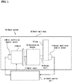
- FIG. 1 is a schematic view showing a main part of a robot system 20 according to the present invention.
- the robot system 20 of the present embodiment includes a motor 8, a deceleration device 18, an arm 15, a motor shaft-side angular sensor 1 for a motor shaft, an output shaft-side angular sensor 2 for an output shaft, and a robot control unit 21.
- the arm 15 is coupled to the motor 8 with the deceleration device 18 interposed therebetween, and thus when the motor 8 is driven and rotated, the arm 15 will rotate.
- the robot system 20 of the present embodiment has a configuration including one motor, one deceleration device, one motor shaft-side angular sensor, one output shaft-side angular sensor, and one arm.
- the present invention is not limited to this, and the robot system may also have a configuration including a plurality of motors, a plurality of deceleration devices, a plurality of motor shaft-side angular sensors, a plurality of output shaft-side angular sensors, and a plurality of arms.
- a servomotor or the like is used as the motor 8. Also, on one end side of the motor 8, one end of a motor shaft 17 is connected to an input shaft of the deceleration device 18, and on the other end of the motor 8, the motor shaft-side angular sensor 1 for the motor shaft is attached.
- an encoder is used as the motor shaft-side angular sensor 1 for the motor shaft, and the encoder is configured to detect the rotation direction and the rotation angle of the motor shaft 17 of the motor 8, and output a measurement signal to the robot control unit 21.
- the motor shaft-side angular sensor 1 is fixed to the motor shaft 17, but due to an inevitable influence of a processing accuracy limit or attachment accuracy for example, the shaft center of the motor shaft-side angular sensor 1 is misaligned with the shaft center of the motor shaft 17.
- the deceleration device 18 is constituted by an unshown plurality of gear wheels, an output shaft 16, and the like.
- the arm 15 is coupled to this output shaft 16, and the output shaft-side angular sensor 2 for the output shaft is attached to an end of the output shaft 16.
- a strain wave gearing which is predominantly subject to elastic torsional deformation, is used as the deceleration device 18.
- the present invention is not limited to this, and may also employ another type of deceleration device that has elastic torsional deformation between the output shaft and the input shaft.
- the output shaft-side angular sensor 2 for the output shaft is also an encoder.
- the output shaft-side angular sensor 2 detects the rotation direction and the rotation angle of the output shaft 16, and outputs a measurement signal to the robot control unit 21.
- the output shaft-side angular sensor 2 is fixed to the output shaft 16, but due to an inevitable influence of a processing accuracy limit or attachment accuracy for example, the shaft center of the output shaft-side angular sensor 2 is misaligned with the shaft center of the output shaft 16.
- the arm 15 has a predetermined length, and is provided with, at the leading end thereof, a tool, a workpiece holding means, or the like, which is not shown.
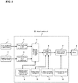
- FIG. 3 is a functional block diagram illustrating a control system (robot control unit 21) of the robot system 20 according to the present invention.
- the robot control unit 21 includes: a motor shaft-side angle calculation unit 3; an output shaft-side angle calculation unit 4; a torsional deformation amount calculation unit 5; a contact determination unit 6; a motor control instruction unit 7; an angular sensor misalignment correction value storage unit 9; a spring constant storage unit 10; a contact determination threshold storage unit 11; and a contact response gain storage unit 12.
- the output shaft-side angle calculation unit 4 calculates an output shaft-side angle ⁇ 2 based on a signal received from the output shaft-side angular sensor 2.
- the angular sensor misalignment correction value ⁇ g is stored, as an array with the output shaft-side angle ⁇ 2 serving as an argument, in the angular sensor misalignment correction value storage unit 9.
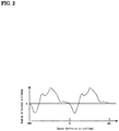
- FIG. 2 is a diagram showing an angular difference when the output shaft 16 is rotated from -360 degrees to +360 degrees with the angular difference ⁇ d plotted on the vertical axis, and the output shaft-side angle ⁇ 2 plotted on the horizontal axis. As shown in FIG. 2 , the same angular difference ⁇ d is observed each time the output shaft 16 is rotated 360 degrees.
- the angular sensor misalignment correction value the relationship between the angular difference ⁇ d and the output shaft-side angle ⁇ 2 when the motor 8 is rotated in an unloaded condition may only be measured in advance.
- contact torque can be calculated from the torsional deformation amount ⁇ is that, if a strain wave gearing, which is predominantly subject to elastic torsional deformation, or the like is used as the deceleration device 18, the torsional deformation amount ⁇ can be treated as being equivalent to an amount of torsion of the deceleration device 18.
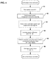
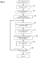
- a flow of the contact torque calculation is shown in FIG. 4 .
- step S1 the contact determination unit 6 reads the spring constant K.
- step S2 the torsional deformation amount calculation unit 5 reads the angular sensor misalignment correction value ⁇ g.
- step S3 the motor shaft-side angle calculation unit 3 calculates the motor shaft-side angle ⁇ 1, and the output shaft-side angle calculation unit 4 calculates the output shaft-side angle ⁇ 2.
- step S5 the torsional deformation amount calculation unit 5 corrects this angular difference using the angular sensor misalignment correction value ⁇ g, and obtains the torsional deformation amount ⁇ .
- the motor control instruction unit 7 transmits an instruction to the motor 8 according to the state of determination of contact between the arm or an instrument attached to the arm and another object, the determination being made by the contact determination unit 6.
- an electric current instruction to instruct the motor 8 to generate rotation torque is transmitted from the motor control instruction unit 7 of the robot control unit 21 to the motor 8 of the robot main body 22.
- FIG. 5 shows a flow in which the robot is stopped upon sensing contact between the arm or the instrument attached to the arm and another object.
- Steps S7, and S9 to S13 are the same as steps S1, and S2 to S6 shown in FIG. 4 .
- the contact determination unit 6 reads the contact determination threshold Tc, and in step S14, the contact determination unit 6 compares the contact torque T with the calculated contact determination threshold Tc, and, if the contact torque T exceeds the contact determination threshold Tc, the motor 8 is stopped.
- FIG. 6 shows a flow in which, upon sensing contact between the arm or the instrument attached to the arm and another object, the robot responds to the contact torque.
- Steps S15, and S18 to S24 are the same as steps S7, and S8 to S14 shown in FIG. 5 .
- the robot control unit 21 shifts the robot to a "contact response mode" in which the robot responds to contact torque.
- step S17 the contact determination unit 6 reads a contact response gain Gv from the contact response gain storage unit 12.
- the contact determination unit 6 calculates a contact response speed Vm in step S25.
- the robot control unit 21 drives the motor 8 at the calculated Vm.
- Steps S27 and S28 are the same as steps S3 and S4 shown in FIG. 4 .
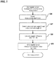
- the motor 8 which is a measurement shaft, is rotated in a state in which no load is provided on the output side of the deceleration device 18.
- the torsional deformation amount calculation unit 5 calculates an angular difference ⁇ d.
- step S29 the torsional deformation amount calculation unit 5 stores the calculated angular difference ⁇ d, serving as the angular sensor misalignment correction value ⁇ g, in the angular sensor misalignment correction value storage unit 9.
- the angular sensor misalignment correction value ⁇ g is an array ⁇ g[ ⁇ 2] with the output shaft-side angle ⁇ 2 serving as an argument. The procedure from steps S26 to S29 is repeated until the output shaft-side angle ⁇ 2 is rotated more than 360 degrees, and the array ⁇ g[ ⁇ 2] of the angular sensor misalignment correction value is completed.
- the present invention is applicable to a robot system that accurately senses contact between an arm of a robot or an instrument attached to the arm and another object.
Landscapes
- Engineering & Computer Science (AREA)
- Robotics (AREA)
- Mechanical Engineering (AREA)
- Human Computer Interaction (AREA)
- Manipulator (AREA)
Claims (2)
- Robotersystem (20), aufweisend:einen Roboterhauptkörper (22) und eine Robotersteuereinheit (21),wobei der Roboterhauptkörper (22) umfasst:einen Motor (8);eine Verzögerungseinrichtung (18), die mit einer Motorwelle (17) des Motors (8) verbunden ist;einen Arm (15), der mit einer Abtriebswelle (16) der Verzögerungseinrichtung (18) verbunden ist;einen motorwellenseitigen Winkelsensor (1), der zum Erfassen eines Drehwinkels der Motorwelle (17) des Motors (8) eingerichtet ist; undeinen abtriebswellenseitigen Winkelsensor (2), der zum Erfassen eines Drehwinkels der Abtriebswelle (16) der Verzögerungseinrichtung (18) eingerichtet ist, undwobei die Robotersteuereinheit (21) dazu eingerichtet ist, einen Kontaktzustand zwischen dem Arm (15) oder eines an dem Arm (15) befestigten Instruments und einem anderen Objekt zu erkennen,wobei die Robotersteuereinheit (21) umfasst;eine Winkelsensor-Fehlausrichtungskorrekturwert-Speichereinheit (9), die dazu eingerichtet ist, einen Winkelsensor-Fehlausrichtungskorrekturwert (θg) zu speichern, wobei der Winkelsensor-Fehlausrichtungskorrekturwert (θg) ein berechneter Wert ist, der auf der Grundlage eines Betrags einer Fehlausrichtung berechnet wird, wenn der motorwellenseitige Winkelsensor (1) und der abtriebswellenseitige Winkelsensor (2) angebracht sind, wobei an einer Endseite des Motors (8) ein Ende der Motorwelle (17) mit einer Eingangswelle der Verzögerungseinrichtung (18) verbunden ist, und an einem anderen Ende des Motors (8) der motorwellenseitige Winkelsensor (1) für die Motorwelle (17) angebracht ist;eine motorwellenseitige Winkelberechnungseinheit (3), die dazu eingerichtet ist, einen motorwellenseitigen Winkel (θ1) auf der Grundlage des Drehwinkels auf der Motorwellenseite zu berechnen;eine abtriebswellenseitige Winkelberechnungseinheit (4), die dazu eingerichtet ist, einen abtriebswellenseitigen Winkel (θ2) auf der Grundlage des Drehwinkels auf der Abtriebswellenseite zu berechnen;eine Torsionsverformungsbetrag-Berechnungseinheit (5), die dazu eingerichtet ist, eine Winkeldifferenz (Δθd) zwischen dem motorwellenseitigen Winkel (θ1) und dem abtriebswellenseitigen Winkel (θ2) zu berechnen und die berechnete Winkeldifferenz (Δθd) unter Verwendung des Winkelsensor-Fehlausrichtungskorrekturwertes (θg) zu korrigieren, um einen Torsionsverformungsbetrag (Δθ) zu erhalten;eine Federkonstanten-Speichereinheit (10), die dazu eingerichtet ist, eine Federkonstante (K) eines Bereichs zwischen dem Motor (8) und dem Arm (15) zu speichern;eine Kontaktbestimmungs-Schwellenwert-Speichereinheit (11), die dazu eingerichtet ist, ein zulässiges Kontaktdrehmoment (Tc) des Arms (15) zu speichern;eine Kontaktbestimmungseinheit (6), die dazu eingerichtet ist, ein Kontaktdrehmoment (T) des Arms (15) auf der Grundlage des Torsionsverformungsbetrags (Δθ) und der in der Federkonstanten-Speichereinheit (10) gespeicherten Federkonstante (K) zu berechnen und den Kontaktzustand zu erfassen, wenn das berechnete Kontaktdrehmoment (T) größer als das in der Kontaktbestimmungs-Schwellenwert-Speichereinheit (11) gespeicherte zulässige Kontaktdrehmoment (Tc) ist;und eine Motorsteuerbefehlseinheit (7), die dazu eingerichtet ist, den Motor (8) anzuhalten, wenn der Kontaktzustand von der Kontaktbestimmungseinheit (6) erfasst wird.
- Robotersystem (20), aufweisend:einen Roboterhauptkörper (22) und eine Robotersteuereinheit (21),wobei der Roboterhauptkörper (22) umfasst:einen Motor (8);eine Verzögerungseinrichtung (18), die mit einer Motorwelle (17) des Motors (8) verbunden ist;einen Arm (15), der mit einer Abtriebswelle (16) der Verzögerungseinrichtung (18) verbunden ist;einen motorwellenseitigen Winkelsensor (1), der zum Erfassen eines Drehwinkels der Motorwelle (17) des Motors (8) eingerichtet ist; undeinen abtriebswellenseitigen Winkelsensor (2), der zum Erfassen eines Drehwinkels der Abtriebswelle (16) der Verzögerungseinrichtung (18) eingerichtet ist, undwobei die Robotersteuereinheit (21) dazu eingerichtet ist, einen Kontaktzustand zwischen dem Arm (15) oder eines an dem Arm (15) befestigten Instruments und einem anderen Objekt zu erkennen,wobei die Robotersteuereinheit (21) umfasst;eine Winkelsensor-Fehlausrichtungskorrekturwert-Speichereinheit (9), die dazu eingerichtet ist, einen Winkelsensor-Fehlausrichtungskorrekturwert (θg) zu speichern, wobei der Winkelsensor-Fehlausrichtungskorrekturwert (θg) ein berechneter Wert ist, der auf der Grundlage eines Betrags der Fehlausrichtung berechnet wird, wenn der motorwellenseitige Winkelsensor (1) und der abtriebswellenseitige Winkelsensor (2) angebracht sind, wobei an einer Endseite des Motors (8) ein Ende der Motorwelle mit einer Eingangswelle der Verzögerungseinrichtung (18) verbunden ist, und am anderen Ende des Motors (8) der motorwellenseitige Winkelsensor (1) für die Motorwelle (17) angebracht ist;eine motorwellenseitige Winkelberechnungseinheit (3), die dazu eingerichtet ist, einen motorwellenseitigen Winkel (θ1) auf der Grundlage des Drehwinkels auf der Motorwellenseite zu berechnen;eine abtriebswellenseitige Winkelberechnungseinheit (4), die dazu eingerichtet ist, einen abtriebswellenseitigen Winkel (θ2) auf der Grundlage des Drehwinkels auf der Abtriebswellenseite zu berechnen;eine Torsionsverformungsbetrag-Berechnungseinheit (5), die dazu eingerichtet ist, eine Winkeldifferenz (Δθd) zwischen dem motorwellenseitigen Winkel (θ1) und dem abtriebswellenseitigen Winkel (θ2) zu berechnen und die berechnete Winkeldifferenz (Δθd) unter Verwendung des Winkelsensor-Fehlausrichtungskorrekturwertes (θg) zu korrigieren, um einen Torsionsverformungsbetrag (Δθ) zu erhalten;eine Federkonstanten-Speichereinheit (10), die dazu eingerichtet ist, eine Federkonstante (K) eines Bereichs zwischen dem Motor (8) und dem Arm (15) zu speichern;eine Kontaktbestimmungs-Schwellenwert-Speichereinheit (11), die dazu eingerechnet ist, ein zulässiges Kontaktdrehmoment (Tc) des Arms (15) zu speichern;eine Kontaktbestimmungseinheit (6), die dazu eingerichtet ist, ein Kontaktdrehmoment (T) des Arms (15) auf der Grundlage des Torsionsverformungsbetrags (Δθ) und der in der Federkonstanten-Speichereinheit (10) gespeicherten Federkonstante (K) zu berechnen und den Kontaktzustand zu erfassen, wenn das berechnete Kontaktdrehmoment (T) größer als das in der Kontaktbestimmungs-Schwellenwert-Speichereinheit (11) gespeicherte zulässige Kontaktdrehmoment (Tc) ist;eine Kontaktreaktionsverstärkungs-Speichereinheit (12), die dazu eingerichtet ist, eine Kontaktreaktionsverstärkung des Arms (15) zu speichern;und eine Motorsteuerungs-Befehlseinheit (7), die dazu eingerichtet ist, den Motor (8) mit einer Geschwindigkeit anzutreiben, die durch Multiplizieren einer Differenz zwischen dem Kontaktdrehmoment (T) und dem zulässigen Kontaktdrehmoment (Tc) mit der Kontaktreaktionsverstärkung erhalten wird, wenn der Kontaktzustand von der Kontaktbestimmungseinheit (6) erfasst wird.
Applications Claiming Priority (2)
| Application Number | Priority Date | Filing Date | Title |
|---|---|---|---|
| JP2017092029 | 2017-05-03 | ||
| PCT/JP2018/016576 WO2018203492A1 (ja) | 2017-05-03 | 2018-04-24 | ロボットシステム |
Publications (3)
| Publication Number | Publication Date |
|---|---|
| EP3620277A1 EP3620277A1 (de) | 2020-03-11 |
| EP3620277A4 EP3620277A4 (de) | 2020-07-01 |
| EP3620277B1 true EP3620277B1 (de) | 2021-11-17 |
Family
ID=64016597
Family Applications (1)
| Application Number | Title | Priority Date | Filing Date |
|---|---|---|---|
| EP18794768.4A Active EP3620277B1 (de) | 2017-05-03 | 2018-04-24 | Robotersystem |
Country Status (5)
| Country | Link |
|---|---|
| US (1) | US11123868B2 (de) |
| EP (1) | EP3620277B1 (de) |
| JP (1) | JP6839369B2 (de) |
| CN (1) | CN110831730B (de) |
| WO (1) | WO2018203492A1 (de) |
Families Citing this family (5)
| Publication number | Priority date | Publication date | Assignee | Title |
|---|---|---|---|---|
| CN109011651B (zh) * | 2018-07-25 | 2020-06-09 | 上海葡萄纬度科技有限公司 | 一种交互式玩具 |
| DE102018133349A1 (de) * | 2018-12-21 | 2020-06-25 | Pilz Gmbh & Co. Kg | Verfahren und Vorrichtung zur Momentschätzung |
| CN111376256A (zh) * | 2018-12-29 | 2020-07-07 | 深圳市优必选科技有限公司 | 一种舵机角度校准方法、系统、机器人及存储介质 |
| CN116262413A (zh) * | 2021-12-14 | 2023-06-16 | 浙江春风动力股份有限公司 | 车用稳定杆的控制系统及方法 |
| CN117484240B (zh) * | 2024-01-02 | 2024-03-29 | 宁波中意液压马达有限公司 | 一种刀塔旋转分度摆线马达 |
Family Cites Families (16)
| Publication number | Priority date | Publication date | Assignee | Title |
|---|---|---|---|---|
| JPH07337055A (ja) * | 1994-06-03 | 1995-12-22 | Yaskawa Electric Corp | ロボットの制御装置 |
| JP3611147B2 (ja) * | 1996-02-20 | 2005-01-19 | 株式会社安川電機 | 多軸ロボットの制御装置 |
| JP3492583B2 (ja) * | 2000-03-27 | 2004-02-03 | ファナック株式会社 | サーボ制御装置 |
| JP2003039376A (ja) | 2001-07-30 | 2003-02-13 | Yaskawa Electric Corp | 衝突検出センサ |
| JP4305323B2 (ja) * | 2004-08-11 | 2009-07-29 | ソニー株式会社 | ロボット装置の動作制御装置及び動作制御方法 |
| JP2010228028A (ja) * | 2009-03-26 | 2010-10-14 | Nec Corp | ロボットアーム、ロボットアームの接触検知方法、及び、ロボットアームを備えた装置 |
| JP5400473B2 (ja) * | 2009-05-22 | 2014-01-29 | 川崎重工業株式会社 | ロボット装置 |
| JP5821210B2 (ja) * | 2011-02-22 | 2015-11-24 | セイコーエプソン株式会社 | 水平多関節ロボット及び水平多関節ロボットの制御方法 |
| JP5849451B2 (ja) * | 2011-06-16 | 2016-01-27 | セイコーエプソン株式会社 | ロボットの故障検出方法、制御装置およびロボット |
| JP5765686B2 (ja) * | 2012-03-23 | 2015-08-19 | トヨタ自動車東日本株式会社 | ロボット接触検知装置 |
| US9733137B2 (en) * | 2012-12-22 | 2017-08-15 | Schaft Inc. | Rotational drive device |
| JP6164948B2 (ja) * | 2013-06-20 | 2017-07-19 | キヤノン株式会社 | ロボット装置及び部品の製造方法 |
| JP5905443B2 (ja) * | 2013-12-25 | 2016-04-20 | ファナック株式会社 | 人協調型産業用ロボットの外力判定方法および外力判定装置 |
| JP6206226B2 (ja) * | 2014-02-04 | 2017-10-04 | 株式会社デンソーウェーブ | ロボット |
| WO2015137038A1 (ja) * | 2014-03-14 | 2015-09-17 | ソニー株式会社 | ロボットアーム装置、ロボットアーム制御方法及びプログラム |
| JP2016221615A (ja) * | 2015-05-29 | 2016-12-28 | キヤノン株式会社 | ロボット装置の診断方法、およびロボットシステム |
-
2018
- 2018-04-24 CN CN201880044091.5A patent/CN110831730B/zh active Active
- 2018-04-24 EP EP18794768.4A patent/EP3620277B1/de active Active
- 2018-04-24 JP JP2019515703A patent/JP6839369B2/ja active Active
- 2018-04-24 WO PCT/JP2018/016576 patent/WO2018203492A1/ja not_active Ceased
- 2018-04-24 US US16/610,328 patent/US11123868B2/en active Active
Also Published As
| Publication number | Publication date |
|---|---|
| US11123868B2 (en) | 2021-09-21 |
| WO2018203492A1 (ja) | 2018-11-08 |
| JPWO2018203492A1 (ja) | 2020-03-19 |
| EP3620277A4 (de) | 2020-07-01 |
| JP6839369B2 (ja) | 2021-03-10 |
| CN110831730B (zh) | 2022-08-16 |
| US20200078942A1 (en) | 2020-03-12 |
| EP3620277A1 (de) | 2020-03-11 |
| CN110831730A (zh) | 2020-02-21 |
Similar Documents
| Publication | Publication Date | Title |
|---|---|---|
| EP3620277A1 (de) | Robotersystem | |
| US9733137B2 (en) | Rotational drive device | |
| US10668620B2 (en) | Method and apparatus for correcting motions of robot | |
| US10564635B2 (en) | Human-cooperative robot system | |
| US4640663A (en) | Balancer and controlling method thereof | |
| US8712589B2 (en) | System and method for judging success or failure of work of robot | |
| EP3067166A1 (de) | Robotersteuerungsverfahren, robotervorrichtung, programm und aufzeichnungsmedium | |
| JP5849451B2 (ja) | ロボットの故障検出方法、制御装置およびロボット | |
| US10670432B2 (en) | Deflection angle detection device | |
| CN102785253A (zh) | 具有机器人的异常检测功能的机器人系统及其控制方法 | |
| US11389959B2 (en) | Robot system | |
| US7500538B2 (en) | Control unit for electric power steering apparatus | |
| US11541541B2 (en) | Gripping system | |
| JP2010269412A (ja) | ロボット装置 | |
| CN112440274B (zh) | 机器人系统 | |
| KR20230116045A (ko) | 로봇, 로봇용 구동 유닛 및 포지셔닝 방법 | |
| KR102425658B1 (ko) | 듀얼 엔코더 기반의 로봇 관절 토크 측정 시스템 | |
| US9209740B2 (en) | Actuating apparatus | |
| JP2019055455A (ja) | ロボットハンド、ロボットハンドの制御方法 | |
| JP7376683B2 (ja) | 力センサの診断装置およびロボット制御装置 | |
| JP6763286B2 (ja) | モータ制御システム | |
| JP2018036097A (ja) | 角度位置検出装置 | |
| JP7000726B2 (ja) | 原点合わせ方法、ロボットシステム | |
| JP7004942B2 (ja) | ロボット制御装置、ロボットシステムおよびロボットアームの接触検知方法 | |
| JPH0411344B2 (de) |
Legal Events
| Date | Code | Title | Description |
|---|---|---|---|
| STAA | Information on the status of an ep patent application or granted ep patent |
Free format text: STATUS: THE INTERNATIONAL PUBLICATION HAS BEEN MADE |
|
| PUAI | Public reference made under article 153(3) epc to a published international application that has entered the european phase |
Free format text: ORIGINAL CODE: 0009012 |
|
| STAA | Information on the status of an ep patent application or granted ep patent |
Free format text: STATUS: REQUEST FOR EXAMINATION WAS MADE |
|
| 17P | Request for examination filed |
Effective date: 20191127 |
|
| AK | Designated contracting states |
Kind code of ref document: A1 Designated state(s): AL AT BE BG CH CY CZ DE DK EE ES FI FR GB GR HR HU IE IS IT LI LT LU LV MC MK MT NL NO PL PT RO RS SE SI SK SM TR |
|
| AX | Request for extension of the european patent |
Extension state: BA ME |
|
| A4 | Supplementary search report drawn up and despatched |
Effective date: 20200529 |
|
| RIC1 | Information provided on ipc code assigned before grant |
Ipc: B25J 19/06 20060101AFI20200525BHEP |
|
| DAV | Request for validation of the european patent (deleted) | ||
| DAX | Request for extension of the european patent (deleted) | ||
| REG | Reference to a national code |
Ref country code: DE Ref legal event code: R079 Ref document number: 602018026915 Country of ref document: DE Free format text: PREVIOUS MAIN CLASS: B25J0019060000 Ipc: B25J0013080000 |
|
| GRAP | Despatch of communication of intention to grant a patent |
Free format text: ORIGINAL CODE: EPIDOSNIGR1 |
|
| STAA | Information on the status of an ep patent application or granted ep patent |
Free format text: STATUS: GRANT OF PATENT IS INTENDED |
|
| RIC1 | Information provided on ipc code assigned before grant |
Ipc: B25J 13/08 20060101AFI20210517BHEP Ipc: B25J 19/06 20060101ALI20210517BHEP |
|
| INTG | Intention to grant announced |
Effective date: 20210608 |
|
| GRAS | Grant fee paid |
Free format text: ORIGINAL CODE: EPIDOSNIGR3 |
|
| GRAA | (expected) grant |
Free format text: ORIGINAL CODE: 0009210 |
|
| STAA | Information on the status of an ep patent application or granted ep patent |
Free format text: STATUS: THE PATENT HAS BEEN GRANTED |
|
| AK | Designated contracting states |
Kind code of ref document: B1 Designated state(s): AL AT BE BG CH CY CZ DE DK EE ES FI FR GB GR HR HU IE IS IT LI LT LU LV MC MK MT NL NO PL PT RO RS SE SI SK SM TR |
|
| REG | Reference to a national code |
Ref country code: GB Ref legal event code: FG4D |
|
| REG | Reference to a national code |
Ref country code: IE Ref legal event code: FG4D |
|
| REG | Reference to a national code |
Ref country code: DE Ref legal event code: R096 Ref document number: 602018026915 Country of ref document: DE |
|
| REG | Reference to a national code |
Ref country code: AT Ref legal event code: REF Ref document number: 1447678 Country of ref document: AT Kind code of ref document: T Effective date: 20211215 |
|
| REG | Reference to a national code |
Ref country code: LT Ref legal event code: MG9D |
|
| REG | Reference to a national code |
Ref country code: NL Ref legal event code: MP Effective date: 20211117 |
|
| REG | Reference to a national code |
Ref country code: AT Ref legal event code: MK05 Ref document number: 1447678 Country of ref document: AT Kind code of ref document: T Effective date: 20211117 |
|
| PG25 | Lapsed in a contracting state [announced via postgrant information from national office to epo] |
Ref country code: RS Free format text: LAPSE BECAUSE OF FAILURE TO SUBMIT A TRANSLATION OF THE DESCRIPTION OR TO PAY THE FEE WITHIN THE PRESCRIBED TIME-LIMIT Effective date: 20211117 Ref country code: LT Free format text: LAPSE BECAUSE OF FAILURE TO SUBMIT A TRANSLATION OF THE DESCRIPTION OR TO PAY THE FEE WITHIN THE PRESCRIBED TIME-LIMIT Effective date: 20211117 Ref country code: FI Free format text: LAPSE BECAUSE OF FAILURE TO SUBMIT A TRANSLATION OF THE DESCRIPTION OR TO PAY THE FEE WITHIN THE PRESCRIBED TIME-LIMIT Effective date: 20211117 Ref country code: BG Free format text: LAPSE BECAUSE OF FAILURE TO SUBMIT A TRANSLATION OF THE DESCRIPTION OR TO PAY THE FEE WITHIN THE PRESCRIBED TIME-LIMIT Effective date: 20220217 Ref country code: AT Free format text: LAPSE BECAUSE OF FAILURE TO SUBMIT A TRANSLATION OF THE DESCRIPTION OR TO PAY THE FEE WITHIN THE PRESCRIBED TIME-LIMIT Effective date: 20211117 |
|
| PG25 | Lapsed in a contracting state [announced via postgrant information from national office to epo] |
Ref country code: IS Free format text: LAPSE BECAUSE OF FAILURE TO SUBMIT A TRANSLATION OF THE DESCRIPTION OR TO PAY THE FEE WITHIN THE PRESCRIBED TIME-LIMIT Effective date: 20220317 Ref country code: SE Free format text: LAPSE BECAUSE OF FAILURE TO SUBMIT A TRANSLATION OF THE DESCRIPTION OR TO PAY THE FEE WITHIN THE PRESCRIBED TIME-LIMIT Effective date: 20211117 Ref country code: PT Free format text: LAPSE BECAUSE OF FAILURE TO SUBMIT A TRANSLATION OF THE DESCRIPTION OR TO PAY THE FEE WITHIN THE PRESCRIBED TIME-LIMIT Effective date: 20220317 Ref country code: PL Free format text: LAPSE BECAUSE OF FAILURE TO SUBMIT A TRANSLATION OF THE DESCRIPTION OR TO PAY THE FEE WITHIN THE PRESCRIBED TIME-LIMIT Effective date: 20211117 Ref country code: NO Free format text: LAPSE BECAUSE OF FAILURE TO SUBMIT A TRANSLATION OF THE DESCRIPTION OR TO PAY THE FEE WITHIN THE PRESCRIBED TIME-LIMIT Effective date: 20220217 Ref country code: NL Free format text: LAPSE BECAUSE OF FAILURE TO SUBMIT A TRANSLATION OF THE DESCRIPTION OR TO PAY THE FEE WITHIN THE PRESCRIBED TIME-LIMIT Effective date: 20211117 Ref country code: LV Free format text: LAPSE BECAUSE OF FAILURE TO SUBMIT A TRANSLATION OF THE DESCRIPTION OR TO PAY THE FEE WITHIN THE PRESCRIBED TIME-LIMIT Effective date: 20211117 Ref country code: HR Free format text: LAPSE BECAUSE OF FAILURE TO SUBMIT A TRANSLATION OF THE DESCRIPTION OR TO PAY THE FEE WITHIN THE PRESCRIBED TIME-LIMIT Effective date: 20211117 Ref country code: GR Free format text: LAPSE BECAUSE OF FAILURE TO SUBMIT A TRANSLATION OF THE DESCRIPTION OR TO PAY THE FEE WITHIN THE PRESCRIBED TIME-LIMIT Effective date: 20220218 Ref country code: ES Free format text: LAPSE BECAUSE OF FAILURE TO SUBMIT A TRANSLATION OF THE DESCRIPTION OR TO PAY THE FEE WITHIN THE PRESCRIBED TIME-LIMIT Effective date: 20211117 |
|
| PG25 | Lapsed in a contracting state [announced via postgrant information from national office to epo] |
Ref country code: SM Free format text: LAPSE BECAUSE OF FAILURE TO SUBMIT A TRANSLATION OF THE DESCRIPTION OR TO PAY THE FEE WITHIN THE PRESCRIBED TIME-LIMIT Effective date: 20211117 Ref country code: SK Free format text: LAPSE BECAUSE OF FAILURE TO SUBMIT A TRANSLATION OF THE DESCRIPTION OR TO PAY THE FEE WITHIN THE PRESCRIBED TIME-LIMIT Effective date: 20211117 Ref country code: RO Free format text: LAPSE BECAUSE OF FAILURE TO SUBMIT A TRANSLATION OF THE DESCRIPTION OR TO PAY THE FEE WITHIN THE PRESCRIBED TIME-LIMIT Effective date: 20211117 Ref country code: EE Free format text: LAPSE BECAUSE OF FAILURE TO SUBMIT A TRANSLATION OF THE DESCRIPTION OR TO PAY THE FEE WITHIN THE PRESCRIBED TIME-LIMIT Effective date: 20211117 Ref country code: DK Free format text: LAPSE BECAUSE OF FAILURE TO SUBMIT A TRANSLATION OF THE DESCRIPTION OR TO PAY THE FEE WITHIN THE PRESCRIBED TIME-LIMIT Effective date: 20211117 Ref country code: CZ Free format text: LAPSE BECAUSE OF FAILURE TO SUBMIT A TRANSLATION OF THE DESCRIPTION OR TO PAY THE FEE WITHIN THE PRESCRIBED TIME-LIMIT Effective date: 20211117 |
|
| REG | Reference to a national code |
Ref country code: DE Ref legal event code: R097 Ref document number: 602018026915 Country of ref document: DE |
|
| PLBE | No opposition filed within time limit |
Free format text: ORIGINAL CODE: 0009261 |
|
| STAA | Information on the status of an ep patent application or granted ep patent |
Free format text: STATUS: NO OPPOSITION FILED WITHIN TIME LIMIT |
|
| 26N | No opposition filed |
Effective date: 20220818 |
|
| PG25 | Lapsed in a contracting state [announced via postgrant information from national office to epo] |
Ref country code: AL Free format text: LAPSE BECAUSE OF FAILURE TO SUBMIT A TRANSLATION OF THE DESCRIPTION OR TO PAY THE FEE WITHIN THE PRESCRIBED TIME-LIMIT Effective date: 20211117 |
|
| PG25 | Lapsed in a contracting state [announced via postgrant information from national office to epo] |
Ref country code: SI Free format text: LAPSE BECAUSE OF FAILURE TO SUBMIT A TRANSLATION OF THE DESCRIPTION OR TO PAY THE FEE WITHIN THE PRESCRIBED TIME-LIMIT Effective date: 20211117 |
|
| REG | Reference to a national code |
Ref country code: CH Ref legal event code: PL |
|
| REG | Reference to a national code |
Ref country code: BE Ref legal event code: MM Effective date: 20220430 |
|
| PG25 | Lapsed in a contracting state [announced via postgrant information from national office to epo] |
Ref country code: MC Free format text: LAPSE BECAUSE OF FAILURE TO SUBMIT A TRANSLATION OF THE DESCRIPTION OR TO PAY THE FEE WITHIN THE PRESCRIBED TIME-LIMIT Effective date: 20211117 Ref country code: LU Free format text: LAPSE BECAUSE OF NON-PAYMENT OF DUE FEES Effective date: 20220424 Ref country code: LI Free format text: LAPSE BECAUSE OF NON-PAYMENT OF DUE FEES Effective date: 20220430 Ref country code: CH Free format text: LAPSE BECAUSE OF NON-PAYMENT OF DUE FEES Effective date: 20220430 |
|
| PG25 | Lapsed in a contracting state [announced via postgrant information from national office to epo] |
Ref country code: BE Free format text: LAPSE BECAUSE OF NON-PAYMENT OF DUE FEES Effective date: 20220430 |
|
| PG25 | Lapsed in a contracting state [announced via postgrant information from national office to epo] |
Ref country code: IE Free format text: LAPSE BECAUSE OF NON-PAYMENT OF DUE FEES Effective date: 20220424 |
|
| PG25 | Lapsed in a contracting state [announced via postgrant information from national office to epo] |
Ref country code: IT Free format text: LAPSE BECAUSE OF FAILURE TO SUBMIT A TRANSLATION OF THE DESCRIPTION OR TO PAY THE FEE WITHIN THE PRESCRIBED TIME-LIMIT Effective date: 20211117 |
|
| PG25 | Lapsed in a contracting state [announced via postgrant information from national office to epo] |
Ref country code: MK Free format text: LAPSE BECAUSE OF FAILURE TO SUBMIT A TRANSLATION OF THE DESCRIPTION OR TO PAY THE FEE WITHIN THE PRESCRIBED TIME-LIMIT Effective date: 20211117 Ref country code: CY Free format text: LAPSE BECAUSE OF FAILURE TO SUBMIT A TRANSLATION OF THE DESCRIPTION OR TO PAY THE FEE WITHIN THE PRESCRIBED TIME-LIMIT Effective date: 20211117 |
|
| PG25 | Lapsed in a contracting state [announced via postgrant information from national office to epo] |
Ref country code: HU Free format text: LAPSE BECAUSE OF FAILURE TO SUBMIT A TRANSLATION OF THE DESCRIPTION OR TO PAY THE FEE WITHIN THE PRESCRIBED TIME-LIMIT; INVALID AB INITIO Effective date: 20180424 |
|
| PG25 | Lapsed in a contracting state [announced via postgrant information from national office to epo] |
Ref country code: MT Free format text: LAPSE BECAUSE OF FAILURE TO SUBMIT A TRANSLATION OF THE DESCRIPTION OR TO PAY THE FEE WITHIN THE PRESCRIBED TIME-LIMIT Effective date: 20211117 |
|
| PG25 | Lapsed in a contracting state [announced via postgrant information from national office to epo] |
Ref country code: TR Free format text: LAPSE BECAUSE OF FAILURE TO SUBMIT A TRANSLATION OF THE DESCRIPTION OR TO PAY THE FEE WITHIN THE PRESCRIBED TIME-LIMIT Effective date: 20211117 |
|
| PGFP | Annual fee paid to national office [announced via postgrant information from national office to epo] |
Ref country code: GB Payment date: 20260313 Year of fee payment: 9 |
|
| PGFP | Annual fee paid to national office [announced via postgrant information from national office to epo] |
Ref country code: FR Payment date: 20260309 Year of fee payment: 9 |
|
| PGFP | Annual fee paid to national office [announced via postgrant information from national office to epo] |
Ref country code: DE Payment date: 20260305 Year of fee payment: 9 |