EP3620338A2 - Automatisches fahrsystem, fahrzeugsteuerungsverfahren und -vorrichtung - Google Patents
Automatisches fahrsystem, fahrzeugsteuerungsverfahren und -vorrichtung Download PDFInfo
- Publication number
- EP3620338A2 EP3620338A2 EP19187253.0A EP19187253A EP3620338A2 EP 3620338 A2 EP3620338 A2 EP 3620338A2 EP 19187253 A EP19187253 A EP 19187253A EP 3620338 A2 EP3620338 A2 EP 3620338A2
- Authority
- EP
- European Patent Office
- Prior art keywords
- equipment
- detected
- detection result
- abnormal
- vehicle
- Prior art date
- Legal status (The legal status is an assumption and is not a legal conclusion. Google has not performed a legal analysis and makes no representation as to the accuracy of the status listed.)
- Granted
Links
Images


Classifications
-
- B—PERFORMING OPERATIONS; TRANSPORTING
- B60—VEHICLES IN GENERAL
- B60W—CONJOINT CONTROL OF VEHICLE SUB-UNITS OF DIFFERENT TYPE OR DIFFERENT FUNCTION; CONTROL SYSTEMS SPECIALLY ADAPTED FOR HYBRID VEHICLES; ROAD VEHICLE DRIVE CONTROL SYSTEMS FOR PURPOSES NOT RELATED TO THE CONTROL OF A PARTICULAR SUB-UNIT
- B60W50/00—Details of control systems for road vehicle drive control not related to the control of a particular sub-unit, e.g. process diagnostic or vehicle driver interfaces
- B60W50/04—Monitoring the functioning of the control system
-
- G—PHYSICS
- G07—CHECKING-DEVICES
- G07C—TIME OR ATTENDANCE REGISTERS; REGISTERING OR INDICATING THE WORKING OF MACHINES; GENERATING RANDOM NUMBERS; VOTING OR LOTTERY APPARATUS; ARRANGEMENTS, SYSTEMS OR APPARATUS FOR CHECKING NOT PROVIDED FOR ELSEWHERE
- G07C5/00—Registering or indicating the working of vehicles
- G07C5/08—Registering or indicating performance data other than driving, working, idle, or waiting time, with or without registering driving, working, idle or waiting time
- G07C5/0808—Diagnosing performance data
-
- B—PERFORMING OPERATIONS; TRANSPORTING
- B60—VEHICLES IN GENERAL
- B60W—CONJOINT CONTROL OF VEHICLE SUB-UNITS OF DIFFERENT TYPE OR DIFFERENT FUNCTION; CONTROL SYSTEMS SPECIALLY ADAPTED FOR HYBRID VEHICLES; ROAD VEHICLE DRIVE CONTROL SYSTEMS FOR PURPOSES NOT RELATED TO THE CONTROL OF A PARTICULAR SUB-UNIT
- B60W50/00—Details of control systems for road vehicle drive control not related to the control of a particular sub-unit, e.g. process diagnostic or vehicle driver interfaces
- B60W50/02—Ensuring safety in case of control system failures, e.g. by diagnosing, circumventing or fixing failures
- B60W50/023—Avoiding failures by using redundant parts
-
- B—PERFORMING OPERATIONS; TRANSPORTING
- B60—VEHICLES IN GENERAL
- B60W—CONJOINT CONTROL OF VEHICLE SUB-UNITS OF DIFFERENT TYPE OR DIFFERENT FUNCTION; CONTROL SYSTEMS SPECIALLY ADAPTED FOR HYBRID VEHICLES; ROAD VEHICLE DRIVE CONTROL SYSTEMS FOR PURPOSES NOT RELATED TO THE CONTROL OF A PARTICULAR SUB-UNIT
- B60W50/00—Details of control systems for road vehicle drive control not related to the control of a particular sub-unit, e.g. process diagnostic or vehicle driver interfaces
- B60W50/08—Interaction between the driver and the control system
-
- B—PERFORMING OPERATIONS; TRANSPORTING
- B60—VEHICLES IN GENERAL
- B60W—CONJOINT CONTROL OF VEHICLE SUB-UNITS OF DIFFERENT TYPE OR DIFFERENT FUNCTION; CONTROL SYSTEMS SPECIALLY ADAPTED FOR HYBRID VEHICLES; ROAD VEHICLE DRIVE CONTROL SYSTEMS FOR PURPOSES NOT RELATED TO THE CONTROL OF A PARTICULAR SUB-UNIT
- B60W60/00—Drive control systems specially adapted for autonomous road vehicles
- B60W60/001—Planning or execution of driving tasks
- B60W60/0015—Planning or execution of driving tasks specially adapted for safety
- B60W60/0018—Planning or execution of driving tasks specially adapted for safety by employing degraded modes, e.g. reducing speed, in response to suboptimal conditions
- B60W60/00186—Planning or execution of driving tasks specially adapted for safety by employing degraded modes, e.g. reducing speed, in response to suboptimal conditions related to the vehicle
-
- G—PHYSICS
- G06—COMPUTING OR CALCULATING; COUNTING
- G06F—ELECTRIC DIGITAL DATA PROCESSING
- G06F11/00—Error detection; Error correction; Monitoring
- G06F11/07—Responding to the occurrence of a fault, e.g. fault tolerance
- G06F11/0703—Error or fault processing not based on redundancy, i.e. by taking additional measures to deal with the error or fault not making use of redundancy in operation, in hardware, or in data representation
- G06F11/0751—Error or fault detection not based on redundancy
-
- G—PHYSICS
- G06—COMPUTING OR CALCULATING; COUNTING
- G06F—ELECTRIC DIGITAL DATA PROCESSING
- G06F11/00—Error detection; Error correction; Monitoring
- G06F11/07—Responding to the occurrence of a fault, e.g. fault tolerance
- G06F11/16—Error detection or correction of the data by redundancy in hardware
- G06F11/20—Error detection or correction of the data by redundancy in hardware using active fault-masking, e.g. by switching out faulty elements or by switching in spare elements
- G06F11/202—Error detection or correction of the data by redundancy in hardware using active fault-masking, e.g. by switching out faulty elements or by switching in spare elements where processing functionality is redundant
- G06F11/2023—Failover techniques
- G06F11/2028—Failover techniques eliminating a faulty processor or activating a spare
-
- G—PHYSICS
- G06—COMPUTING OR CALCULATING; COUNTING
- G06F—ELECTRIC DIGITAL DATA PROCESSING
- G06F11/00—Error detection; Error correction; Monitoring
- G06F11/22—Detection or location of defective computer hardware by testing during standby operation or during idle time, e.g. start-up testing
- G06F11/26—Functional testing
- G06F11/27—Built-in tests
-
- G—PHYSICS
- G06—COMPUTING OR CALCULATING; COUNTING
- G06F—ELECTRIC DIGITAL DATA PROCESSING
- G06F11/00—Error detection; Error correction; Monitoring
- G06F11/30—Monitoring
- G06F11/3003—Monitoring arrangements specially adapted to the computing system or computing system component being monitored
- G06F11/3013—Monitoring arrangements specially adapted to the computing system or computing system component being monitored where the computing system is an embedded system, i.e. a combination of hardware and software dedicated to perform a certain function in mobile devices, printers, automotive or aircraft systems
-
- G—PHYSICS
- G06—COMPUTING OR CALCULATING; COUNTING
- G06F—ELECTRIC DIGITAL DATA PROCESSING
- G06F11/00—Error detection; Error correction; Monitoring
- G06F11/30—Monitoring
- G06F11/3058—Monitoring arrangements for monitoring environmental properties or parameters of the computing system or of the computing system component, e.g. monitoring of power, currents, temperature, humidity, position, vibrations
-
- G—PHYSICS
- G07—CHECKING-DEVICES
- G07C—TIME OR ATTENDANCE REGISTERS; REGISTERING OR INDICATING THE WORKING OF MACHINES; GENERATING RANDOM NUMBERS; VOTING OR LOTTERY APPARATUS; ARRANGEMENTS, SYSTEMS OR APPARATUS FOR CHECKING NOT PROVIDED FOR ELSEWHERE
- G07C5/00—Registering or indicating the working of vehicles
- G07C5/02—Registering or indicating driving, working, idle, or waiting time only
-
- B—PERFORMING OPERATIONS; TRANSPORTING
- B60—VEHICLES IN GENERAL
- B60R—VEHICLES, VEHICLE FITTINGS, OR VEHICLE PARTS, NOT OTHERWISE PROVIDED FOR
- B60R16/00—Electric or fluid circuits specially adapted for vehicles and not otherwise provided for; Arrangement of elements of electric or fluid circuits specially adapted for vehicles and not otherwise provided for
- B60R16/02—Electric or fluid circuits specially adapted for vehicles and not otherwise provided for; Arrangement of elements of electric or fluid circuits specially adapted for vehicles and not otherwise provided for electric constitutive elements
- B60R16/023—Electric or fluid circuits specially adapted for vehicles and not otherwise provided for; Arrangement of elements of electric or fluid circuits specially adapted for vehicles and not otherwise provided for electric constitutive elements for transmission of signals between vehicle parts or subsystems
-
- B—PERFORMING OPERATIONS; TRANSPORTING
- B60—VEHICLES IN GENERAL
- B60W—CONJOINT CONTROL OF VEHICLE SUB-UNITS OF DIFFERENT TYPE OR DIFFERENT FUNCTION; CONTROL SYSTEMS SPECIALLY ADAPTED FOR HYBRID VEHICLES; ROAD VEHICLE DRIVE CONTROL SYSTEMS FOR PURPOSES NOT RELATED TO THE CONTROL OF A PARTICULAR SUB-UNIT
- B60W50/00—Details of control systems for road vehicle drive control not related to the control of a particular sub-unit, e.g. process diagnostic or vehicle driver interfaces
- B60W50/02—Ensuring safety in case of control system failures, e.g. by diagnosing, circumventing or fixing failures
- B60W50/029—Adapting to failures or work around with other constraints, e.g. circumvention by avoiding use of failed parts
- B60W2050/0292—Fail-safe or redundant systems, e.g. limp-home or backup systems
-
- B—PERFORMING OPERATIONS; TRANSPORTING
- B60—VEHICLES IN GENERAL
- B60W—CONJOINT CONTROL OF VEHICLE SUB-UNITS OF DIFFERENT TYPE OR DIFFERENT FUNCTION; CONTROL SYSTEMS SPECIALLY ADAPTED FOR HYBRID VEHICLES; ROAD VEHICLE DRIVE CONTROL SYSTEMS FOR PURPOSES NOT RELATED TO THE CONTROL OF A PARTICULAR SUB-UNIT
- B60W50/00—Details of control systems for road vehicle drive control not related to the control of a particular sub-unit, e.g. process diagnostic or vehicle driver interfaces
- B60W50/02—Ensuring safety in case of control system failures, e.g. by diagnosing, circumventing or fixing failures
- B60W50/029—Adapting to failures or work around with other constraints, e.g. circumvention by avoiding use of failed parts
- B60W2050/0295—Inhibiting action of specific actuators or systems
Definitions
- Embodiments of the present invention relate to the field of automatic driving technologies, and particularly to an automatic driving system, a vehicle control method and a device.
- Automatic driving vehicles can improve road safety and provide people with a new way of mobile travel, making people's lives more convenient. Whether commuting to and from work, remote self-driving tour, or order delivery, fully automatic driving vehicles have great potential.
- An automatic driving vehicle also known as a driverless vehicle, a computer-driven vehicle, or a wheeled mobile robot, is a smart car that can realize self-driving by a computer system, mainly relying on artificial intelligence, visual computing, radar, monitoring equipment and global positioning system to work together, and allowing a computer to operate a motor vehicle automatically and safely without any human active operation.
- the safety of the automatic driving vehicle and the control efficiency of the automatic driving vehicle are the most critical indicators of the automatic driving vehicle.
- the present invention provides an automatic driving system, a vehicle control method and device, which ensure that when an equipment of the vehicle is abnormal, the vehicle is switched to a standby equipment of the equipment in time, which greatly reduces an incidence of a safety accident caused by a failure of the equipment of the system.
- a first aspect of the present invention provides an automatic driving system, including: a primary monitoring equipment, a secondary monitoring equipment, at least one equipment to be detected, and a standby equipment corresponding to each equipment to be detected; the primary monitoring equipment and the secondary monitoring equipment are connected to each equipment to be detected, and the primary monitoring equipment and the secondary monitoring equipment are connected to the standby equipment corresponding to each equipment to be detected; the primary monitoring equipment is connected to the secondary monitoring equipment, the primary monitoring equipment and the secondary monitoring equipment are configured to perform a fault detection on each equipment to be detected and each standby equipment, and control the vehicle to switch between the equipment to be detected and the standby equipment corresponding to the equipment to be detected.
- the at least one equipment to be detected includes at least one of: a vehicle motion equipment, an environment sensing equipment, a vehicle control equipment, or a power equipment.
- the vehicle motion equipment includes at least one of: a speed sensor, an angle sensor, and an integrated navigation equipment.
- the environment sensing equipment includes at least one of: a lidar sensor, a millimeter wave radar sensor, an ultrasonic sensor, and a camera.
- the vehicle control equipment includes at least one of: a brake equipment, a steering equipment, an engine, and a gearbox.
- a second aspect of the present invention provides a vehicle control method, the method is applied to any one of the automatic driving systems in the first aspect of the present invention, the method includes:
- the determining, by a primary monitoring equipment, a detection result of a first equipment to be detected includes: performing, by the primary monitoring equipment, an abnormal detection on the first equipment to be detected, to obtain the detection result.
- the determining, by a primary monitoring equipment, a detection result of a first equipment to be detected includes:
- the method further includes:
- the determining, by the primary monitoring equipment, the detection result according to the first detection result and the second detection result includes:
- the controlling, by the primary monitoring equipment, the vehicle to switch to a standby equipment of the first equipment to be detected to operate includes: sending, by the primary monitoring equipment, a startup command to the standby equipment of the first equipment to be detected, to control the standby equipment to start.
- the detection result includes at least one of an operating parameter, a connection state, a storage state, and a log sequence of the first equipment to be detected.
- the method further includes:
- a third aspect of the present invention provides a vehicle control device including:
- the determining module is specifically configured to perform an abnormal detection on the first equipment to be detected to obtain the detection result.
- the device also includes:
- the device also includes:
- the determining module is specifically configured to:
- the executing module is specifically configured to: send a startup instruction to the standby equipment of the first equipment to be detected, and control the standby equipment to start.
- the detection result includes at least one of an operating parameter, a connection state, a storage state, and a log sequence of the first equipment to be detected.
- the device further includes:
- a fourth aspect of the present invention provides a vehicle control device including:
- a fifth aspect of the invention provides a computer readable storage medium, storing a computer program, which, when being executed by a processor, implements any one of the methods in the second aspect of the present invention.
- the automatic driving system includes a main monitoring equipment, a secondary monitoring equipment, at least one equipment to be detected, and a standby equipment corresponding to each equipment to be detected, wherein the primary monitoring equipment and the secondary monitoring equipment are connected to each equipment to be detected and the standby equipment corresponding to each equipment to be detected, and the primary monitoring equipment is connected to the secondary monitoring equipment; and the control method based on the above system includes determining a detection result of the first equipment to be detected by the primary monitoring equipment, and if the detection result indicates that the first equipment to be detected is abnormal, controlling the vehicle to switch to the standby equipment of the first equipment to be detected to operate.
- the above system and control method ensure that when an equipment of the vehicle is abnormal, the vehicle can be switched to a standby equipment of the equipment in time, which greatly reduces an incidence of a safety accident caused by a failure of the equipment in the system.
- an embodiment or “another embodiment” referred to throughout the specification of the present invention means that a particular feature, structure or characteristic related to the embodiment is included in at least one embodiment of the present application.
- the automatic driving system includes simultaneously performing a fault detection on an equipment to be detected on a vehicle by a primary monitoring equipment and a secondary monitoring equipment, and controlling the vehicle to switch between the equipment to be detected and a standby equipment corresponding to the equipment to be detected if it is determined that the equipment to be detected is abnormal.
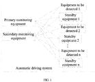
- FIG. 1 is a schematic structural diagram of an automatic driving system according to an embodiment of the present invention. As shown in FIG. 1 , the automatic driving system provided in this embodiment includes:
- FIG. 1 shows n equipments to be detected and n standby equipments corresponding to n equipments to be detected, wherein, n is an integer greater than or equal to 1.
- the primary monitoring equipment includes a first information processing unit and a first communication unit, the first information processing unit is connected to each equipment to be detected, a standby equipment corresponding to each equipment to be detected and the first communication unit, wherein, the first information processing unit is configured to obtain equipment information of each equipment to be detected, and determine whether the equipment to be detected is abnormal according to the equipment information, and the first information processing unit is further configured to obtain equipment information of each equipment to be detected sent by the secondary monitoring equipment, and determine whether the equipment to be detected is abnormal after the data information is synchronized; and the first communication unit is configured to send a control instruction to each equipment to be detected and the standby equipment corresponding to the equipment to be detected.
- the secondary monitoring equipment includes a second information processing unit and a second communication unit, the second information processing unit is connected to each equipment to be detected, a standby equipment corresponding to each equipment to be detected, and the second communication unit, the second communication unit is connected to the first communication unit in the primary monitoring equipment, wherein, the second information processing unit is configured to obtain equipment information of each equipment to be detected, and determine whether the equipment to be detected is abnormal according to the equipment information, and the second communication unit is configured to send equipment information of each equipment to be detected to the first communication unit of the primary monitoring equipment.
- the first information processing unit of the primary monitoring equipment can make a determination according to the equipment information of each equipment to be detected that is obtained by itself, and can also perform a comprehensive evaluation according to the equipment information of each equipment to be detected sent by the secondary monitoring equipment. This embodiment does not specifically limit this.
- the second communication unit is further configured to send a control instruction to each equipment to be detected and the standby equipment corresponding to the equipment to be detected.
- the secondary monitoring equipment makes a determination by the second information processing unit on the basis of the equipment information of each equipment to be detected obtained by the second information processing unit itself, and sends a control instruction to each equipment to be detected and the standby equipment corresponding to the equipment to be detected by the second communication unit.
- the equipment information of the equipment to be detected includes, but is not limited to, an operating parameter, a connection state, a storage state, and a log sequence of the equipment.
- the equipment to be detected includes at least one of the following: a vehicle motion equipment, an environment sensing equipment, a vehicle control equipment, or a power equipment.
- the vehicle motion equipment includes at least one of the following: a speed sensor, an angle sensor, and an integrated navigation equipment.
- the speed sensor and the angle sensor provide relevant transversal and longitudinal information of a line control system of the vehicle;
- the integrated navigation equipment includes an inertial navigation device and a global positioning system, and provides full attitude information parameters and high precision positioning information.
- the environment sensing equipment that is, the environment sensing sensor, is a sensor responsible for environment sensing and similar to human vision and hearing, and without the support of the environment sensing sensor, the automatic driving function will not be realized.
- the environment sensing equipment includes at least one of the following: a lidar sensor, a millimeter wave radar sensor, an ultrasonic sensor, and a camera.
- the data obtained by such as lidar, camera, and millimeter wave radar is fused and provided to a calculation unit for algorithm processing.
- the vehicle control equipment includes at least one of the following: a brake equipment, a steering equipment, an engine, and a gearbox.
- the automatic driving system controls the brake equipment, steering equipment, engine and gearbox of the vehicle through electric signals to realize functions such as adaptive cruising, emergency braking and automatic parking.
- the primary monitoring equipment includes a plurality of first information processing units
- the secondary monitoring equipment includes a plurality of second information processing units.
- Different first information processing units are configured to process the equipment information of different equipments to be detected, and determine the detection result of each equipment to be detected; and different second information processing units are configured to process the equipment information of different equipments to be detected, and determine the detection result of each equipment to be detected.
- the primary monitoring equipment may determine whether to switch the vehicle to the standby equipment of the equipment to be detected according to the detection result of the equipment to be detected determined by a corresponding second information processing unit in the secondary monitoring equipment.
- the detection result is directly determined by the secondary monitoring equipment to determine whether to switch the vehicle to the standby equipment of the equipment to be detected.
- the plurality of second information processing units of the secondary monitoring equipment are only used to detect an important equipment to be detected on the vehicle, in other words, the number of second information processing units of the secondary monitoring equipment is smaller than the number of first information processing units of the primary monitoring equipment.
- the automatic driving system includes a primary monitoring equipment, a secondary monitoring equipment, at least one equipment to be detected, and a standby equipment corresponding to each equipment to be detected, wherein the primary monitoring equipment and the secondary monitoring equipment are connected to each equipment to be detected and the standby equipment corresponding to each equipment to be detected, the primary monitoring equipment is connected to the secondary monitoring equipment, and the primary monitoring equipment and the secondary monitoring equipment are configured to perform a fault detection on each equipment to be detected and each standby equipment, and control the vehicle to switch between the equipment to be detected and the standby equipment corresponding to the equipment to be detected.
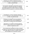
- FIG. 2 is a schematic flow chart of a vehicle control method according to an embodiment of the present invention, the method can be performed by any device for performing the vehicle control method, and the device can be implemented in software and/or hardware.
- the vehicle control method provided in this embodiment includes the following steps:
- the first equipment to be detected is one of a vehicle motion equipment, an environment sensing equipment, a vehicle control equipment, and a power equipment
- the vehicle motion equipment includes, but is not limited to, a speed sensor, an angle sensor, and an integrated navigation equipment
- the environment sensing equipment includes, but is not limited to, a lidar sensor, a millimeter wave radar sensor, an ultrasonic sensor, and a camera
- the vehicle control equipment includes, but is not limited to, a brake equipment, a steering equipment, an engine, a gearbox.
- the first equipment to be detected is an engine, when the primary monitoring equipment detects that an operating parameter of the engine (such as, operating frequency, voltage, etc.) exceeds a preset value, an obtained detection result is that the operating parameter is abnormal; if the first equipment to be detected is a lidar sensor, when the primary monitoring equipment detects that the lidar sensor is not connected, an obtained detection result is that the connection state is abnormal; if the first equipment to be detected is a power equipment, when the primary monitoring equipment detects that the power of the power equipment is lower than a preset power, an obtained detection result is that the storage state of the power is abnormal; and if a log sequence of the first equipment to be detected is inconsistent with a normal log sequence of a preset scene, an obtained detection result is that the log sequence is abnormal.
- an operating parameter of the engine such as, operating frequency, voltage, etc.
- the primary monitoring equipment determines that the first equipment to be detected is abnormal according to the detection result, it sends a startup command to the standby equipment of the first equipment to be detected, to control the standby equipment to start.
- the primary monitoring equipment determines that the first equipment to be detected is abnormal according to the detection result, it sends a fault repair instruction to the first equipment to be detected, wherein the fault repair instruction is used to instruct the first equipment to be detected to perform an equipment self-test and repair.
- the vehicle control method provided by this embodiment of the present invention includes determining, by a primary monitoring equipment, a detection result of a first equipment to be detected, and if the detection result indicates that the first equipment to be detected is abnormal, controlling, by the primary monitoring equipment, the vehicle to switch to a standby equipment corresponding to the first equipment to be detected to operate.
- the above control method ensures that when an equipment of the vehicle is abnormal, the vehicle is switched to a standby equipment of the equipment in time, which greatly reduces an incidence of a safety accident caused by a failure of the equipment.
- FIG. 3 is a schematic flowchart of a vehicle control method according to another embodiment of the present invention.
- the vehicle control method provided in this embodiment includes the following steps: S301: performing, by a primary monitoring equipment, an abnormal detection on a first equipment to be detected, to obtain a detection result.
- a first information processing unit of the primary monitoring equipment obtains equipment information of the first equipment to be detected, and determines whether the first equipment to be detected is abnormal according to the equipment information, and determines a detection result.
- the detection result includes an abnormal detection result and a normal detection result.
- a first communication unit of the primary monitoring equipment sends a startup command to the standby equipment corresponding to the first equipment to be detected, and controls the standby equipment of the first equipment to be detected to start operation, completing the switching of the primary standby equipment.
- the primary monitoring equipment performs an abnormal detection on the first equipment to be detected, and if the detection result is an abnormal detection result, the control vehicle is controlled to switch to the standby equipment corresponding to the first equipment to be detected.
- a fault emergency response mechanism is realized, avoiding an immediate failure of the vehicle due to a faulty equipment.
- FIG. 4 is a schematic flow chart of a vehicle control method according to another embodiment of the present invention. As shown in FIG. 4 , the vehicle control method provided in this embodiment includes the following steps:
- a first communication unit of the primary monitoring equipment receives the second detection result of the first equipment to be detected sent by a second communication unit of the secondary monitoring equipment, wherein, the second test result includes an abnormal detection result and a normal detection result.
- the second detection result may be the same as or different from the first detection result.
- S403 determining, by the primary monitoring equipment, a detection result according to the first detection result and the second detection result; Specifically, if the first detection result indicates that the first equipment to be detected is abnormal, and the second detection result indicates that the first equipment to be detected is abnormal, the first equipment to be detected is determined as abnormal; if the first detection result indicates that the first equipment to be detected is abnormal, and the second detection result indicates that the first equipment to be detected is normal, the first equipment to be detected is determined as normal.
- S401 and S404 in this embodiment have the same principles and technical effects as S301 and S302 in the foregoing embodiment, respectively, and details may be found in the foregoing embodiment, and details are not described here again.
- the primary monitoring equipment obtains a comprehensive detection result according to the first detection result of the first equipment to be detected obtained by the primary monitoring equipment itself and the second detection result of the first equipment to be detected sent by the secondary monitoring equipment, and if the comprehensive detection result is an abnormal detection result, the vehicle is controlled to switch to the standby equipment corresponding to the first equipment to be detected to operate.
- the above determining process integrates the detection results of the primary monitoring equipment and the secondary monitoring equipment, avoiding an unnecessary equipment switching caused by misjudgment of the primary monitoring equipment, and improving the accuracy of the system emergency response mechanism.
- FIG. 5 is a schematic flowchart of a vehicle control method according to still another embodiment of the present invention. As shown in FIG. 5 , the vehicle control method provided in this embodiment includes the following steps:
- the above detection result includes an abnormal detection result and a normal detection result.
- S502 if the detection result indicates that the first equipment to be detected is abnormal, sending, by the primary monitoring equipment, a fault detection instruction to the first equipment to be detected, wherein the fault detection instruction is used to indicate the first equipment to be detected to performs a self-test;
- S503 receiving, by the primary monitoring equipment, a self-test result fed back by the first equipment to be detected, and updating the detection result according to the self-test result;
- the primary monitoring equipment sends a failure detection instruction to the first equipment to be detected, and if the self-test result obtained by the self-test of the first equipment to be detected is normal, the self-test result is used as the detection result in S501, and an equipment switching is not performed; if the self-test result obtained by the self-test of the first equipment to be detected is still abnormal, then S504 is performed.
- S504 in this embodiment has the same principle and the technical effect as S302 in the foregoing embodiment, and details can be found in the foregoing embodiment, and details are not described here again.
- the primary monitoring equipment after determining that the comprehensive detection result of the first equipment to be detected is an abnormal detection result according to the first detection result and the second detection result, the primary monitoring equipment sends a failure self-test instruction to the first equipment to be detected, and if the returned self-test result is still abnormal, then the vehicle is controlled to switch to the standby equipment corresponding to the first equipment to be detected; if the returned self-test result is normal, an equipment switching is not performed.
- the primary monitoring equipment, the secondary monitoring equipment and a self-test device of the first equipment to be detected are combined to obtain the detection result, avoiding an unnecessary equipment switching, and improving the accuracy and flexibility of the system fault emergency response mechanism.
- FIG. 6 is a schematic flowchart of a vehicle control method according to still another embodiment of the present invention.
- the vehicle control method provided in this embodiment describes a fault recovery mechanism in detail.
- the vehicle control method provided in this embodiment includes the following steps:
- the first equipment to be detected performs the equipment self-test and repair according to the fault repair instruction sent by the primary monitoring equipment, and if the fault is removed, the first equipment to be detected sends fault cancellation information to the primary monitoring equipment.
- S604 controlling, by the primary monitoring equipment, the vehicle to switch to the first equipment to be detected to operate according to the fault cancellation information.
- the primary monitoring equipment sends a shutdown instruction to the standby equipment of the first equipment to be detected according to the fault cancellation information, and controls the standby equipment to stop operating. At the same time, the primary monitoring equipment sends a startup instruction to the first equipment to be detected and controls the first equipment to be detected to start operating.
- the primary monitoring equipment controls the vehicle to switch back to the primary equipment according to the fault cancellation information sent by the first equipment to be detected, realizing a self-starting mechanism of the primary equipment of the vehicle after fault repair, and improving the automatic control function of the system.
- An embodiment of the present invention further provides a vehicle control device, referring to FIG. 7 .
- the embodiment of the present invention is illustrated only by FIG. 7 as an example, and the present invention is not limited thereto.
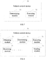
- FIG. 7 is a schematic structural diagram of a vehicle control device according to an embodiment of the present invention. As shown in FIG. 7 , this embodiment provides a vehicle control device 70, including:
- the determining module 71 is specifically configured to perform an abnormal detection on the first equipment to be detected to obtain the detection result.
- the vehicle control device provided by the embodiment of the present invention includes a determining module and an executing module, wherein the determining module is configured to determine the detection result of the first equipment to be detected, and if the detection result indicates that the first equipment to be detected is abnormal, the executing module is configured to control the vehicle to switch to the standby equipment corresponding to the first equipment to be detected to operate.
- the above vehicle control device ensures that when an equipment of the vehicle is abnormal, the vehicle is switched to a standby equipment of the equipment in time, which greatly reduces an incidence of a safety accident caused by a failure of the equipment.
- FIG. 8 is a schematic structural diagram of a vehicle control device according to another embodiment of the present invention.
- the vehicle control device 70 provided in this embodiment as shown in FIG. 8 further includes:
- the vehicle control device 70 further includes:
- the determining module 71 is specifically configured to:
- the executing module 72 is specifically configured to: send a startup instruction to the standby equipment of the first equipment to be detected, and control the standby equipment to start.
- the detection result includes at least one of an operating parameter, a connection state, a storage state, and a log sequence of the first equipment to be detected.
- the vehicle control device 70 further includes:
- the vehicle control device provided in this embodiment can perform the technical solution of the foregoing method embodiment, and its implementation principle and technical effect are similar to the latter, and details are not described here again.
- An embodiment of the present invention further provides a vehicle control device, referring to FIG. 9 .
- This embodiment of the present invention is illustrated only by FIG. 9 as an example, and the present invention is not limited thereto.
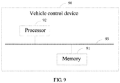
- FIG. 9 is a schematic structural diagram of hardware of a vehicle control device according to an embodiment of the present invention. As shown in FIG. 9 , this embodiment provides a vehicle control device 90, including:
- the memory 91 can be either independent or integrated with the processor 92.
- the vehicle control device 90 also includes: a bus 93 for connecting the memory 91 and the processor 92.
- An embodiment of the present invention also provides a computer readable storage medium having a computer program stored thereon that, being executed by the processor 92, implements various steps performed by the vehicle control device 90 in the method embodiment above.
- processor may be a central processing unit (CPU), and may also be other general purpose processor, digital signal processor (DSP), application specific integrated circuit (ASIC), etc.
- DSP digital signal processor
- ASIC application specific integrated circuit
- the general purpose processor may be a microprocessor, or any conventional processor, etc. The steps of the method disclosed in connection with the present invention may be directly implemented by an execution of a hardware processor or by a combination of hardware and software modules in the processor.
- the memory may contain high speed RAM memory and may also include non-volatile memory NVM, such as at least one disk storage, can also be a U disk, a mobile hard disk, a read-only memory, a magnetic disk or an optical disk, etc.
- NVM non-volatile memory
- the bus can be an Industry Standard Architecture (ISA) bus, a peripheral component interconnect (PCI) bus, or an extended industry standard architecture (ESA) bus, etc.
- ISA Industry Standard Architecture
- PCI peripheral component interconnect
- ESA extended industry standard architecture
- the bus can be divided into an address bus, a data bus, a control bus, etc.
- the bus in the drawings of the present application does not be limited to only one bus or one type of bus.
- the above storage medium may be implemented by any type of volatile or non-volatile storage device or a combination thereof, such as a static random access memory (SRAM), an electrically erasable programmable read only memory (EEPROM), an erasable programmable read only memory (EPROM), a programmable read only memory (PROM), a read only Memory (ROM), a magnetic memory, a flash memory, a magnetic disk or an optical disk.
- SRAM static random access memory
- EEPROM electrically erasable programmable read only memory
- EPROM erasable programmable read only memory
- PROM programmable read only Memory
- ROM read only Memory
- magnetic memory a magnetic memory
- flash memory a magnetic disk or an optical disk.
- An exemplary storage medium is coupled to a processor to enable the processor to read information from, and write information to, the storage medium.
- the storage medium can also be part of the processor.
- the processor and the storage medium may be located in an application specific integrated circuit (ASIC).
- ASIC application specific integrated circuit
- the processor and the storage medium can also exist as discrete components in an electronic device or a master device.
Landscapes
- Engineering & Computer Science (AREA)
- Theoretical Computer Science (AREA)
- Physics & Mathematics (AREA)
- General Physics & Mathematics (AREA)
- Automation & Control Theory (AREA)
- General Engineering & Computer Science (AREA)
- Mechanical Engineering (AREA)
- Quality & Reliability (AREA)
- Transportation (AREA)
- Human Computer Interaction (AREA)
- Computing Systems (AREA)
- Mathematical Physics (AREA)
- Computer Hardware Design (AREA)
- Control Of Driving Devices And Active Controlling Of Vehicle (AREA)
- Electric Propulsion And Braking For Vehicles (AREA)
- Safety Devices In Control Systems (AREA)
- Testing And Monitoring For Control Systems (AREA)
Applications Claiming Priority (1)
| Application Number | Priority Date | Filing Date | Title |
|---|---|---|---|
| CN201811042244.0A CN109367501B (zh) | 2018-09-07 | 2018-09-07 | 自动驾驶系统、车辆控制方法及装置 |
Publications (3)
| Publication Number | Publication Date |
|---|---|
| EP3620338A2 true EP3620338A2 (de) | 2020-03-11 |
| EP3620338A3 EP3620338A3 (de) | 2020-08-26 |
| EP3620338B1 EP3620338B1 (de) | 2022-02-16 |
Family
ID=65405410
Family Applications (1)
| Application Number | Title | Priority Date | Filing Date |
|---|---|---|---|
| EP19187253.0A Active EP3620338B1 (de) | 2018-09-07 | 2019-07-19 | Fahrzeugsteuerungsverfahren |
Country Status (4)
| Country | Link |
|---|---|
| US (1) | US11308739B2 (de) |
| EP (1) | EP3620338B1 (de) |
| JP (1) | JP6820981B2 (de) |
| CN (1) | CN109367501B (de) |
Cited By (3)
| Publication number | Priority date | Publication date | Assignee | Title |
|---|---|---|---|---|
| CN111791896A (zh) * | 2020-07-17 | 2020-10-20 | 北京易控智驾科技有限公司 | 无人驾驶车辆的安全控制方法及系统 |
| CN115225555A (zh) * | 2022-05-17 | 2022-10-21 | 广州汽车集团股份有限公司 | 车联网终端的测试方法、系统、装置、电子设备及介质 |
| WO2025011901A1 (de) * | 2023-07-11 | 2025-01-16 | Zf Cv Systems Europe Bv | Fahrzeugsteuersystem zum autonomen steuern eines fahrzeugs sowie verfahren damit |
Families Citing this family (23)
| Publication number | Priority date | Publication date | Assignee | Title |
|---|---|---|---|---|
| JP7202112B2 (ja) * | 2018-09-11 | 2023-01-11 | 本田技研工業株式会社 | 車両用制御システムおよび車両の制御方法 |
| CN110040084A (zh) * | 2019-03-22 | 2019-07-23 | 深圳市速腾聚创科技有限公司 | 传感器稳定性的提升方法、系统、装置、设备和存储介质 |
| CN110053630B (zh) * | 2019-06-06 | 2021-09-03 | 百度在线网络技术(北京)有限公司 | 车辆控制方法及装置 |
| CN113365878B (zh) * | 2019-09-03 | 2025-06-06 | 北京航迹科技有限公司 | 自动驾驶系统的冗余结构 |
| CN112572147A (zh) * | 2019-09-27 | 2021-03-30 | 中车株洲电力机车研究所有限公司 | 一种人机交互系统 |
| CN110867132B (zh) * | 2019-10-15 | 2022-03-01 | 阿波罗智能技术(北京)有限公司 | 环境感知的方法、装置、电子设备和计算机可读存储介质 |
| EP4045373A4 (de) | 2019-10-16 | 2023-11-15 | LHP, Inc. | Sicherheitsüberwachungssystem für fahrzeuge |
| CN110682920B (zh) * | 2019-12-09 | 2020-04-21 | 吉利汽车研究院(宁波)有限公司 | 一种自动驾驶控制系统、控制方法及设备 |
| CN110816443B (zh) * | 2020-01-13 | 2020-04-21 | 中智行科技有限公司 | 车辆监测方法、装置以及无人驾驶车辆 |
| CN112109728B (zh) * | 2020-08-19 | 2023-01-24 | 浙江吉利汽车研究院有限公司 | 一种自动驾驶故障控制方法、系统、设备及存储介质 |
| CN114194121B (zh) * | 2020-09-02 | 2023-05-12 | 宇通客车股份有限公司 | 一种辅助驾驶系统和车辆 |
| JP6991294B1 (ja) * | 2020-10-09 | 2022-01-12 | 三菱電機株式会社 | 制御装置 |
| CN112230625B (zh) * | 2020-10-30 | 2022-04-01 | 北京汽车研究总院有限公司 | 智能驾驶控制器的车辆控制方法及存储介质与计算机设备 |
| CA3197021A1 (en) * | 2020-10-30 | 2022-05-05 | Hongchao RUAN | Information transmission method, control apparatus, electromagnetic signal transceiver apparatus, and signal processing device |
| CN112445667B (zh) * | 2020-12-11 | 2024-09-13 | 上海商汤临港智能科技有限公司 | 一种检测方法、装置、计算机设备及存储介质 |
| JP2022150683A (ja) * | 2021-03-26 | 2022-10-07 | 富士通株式会社 | 検証システムおよび検証装置 |
| CN113043969B (zh) * | 2021-03-26 | 2022-12-16 | 中汽创智科技有限公司 | 一种车辆功能安全监控方法及系统 |
| CN113586263B (zh) * | 2021-07-27 | 2023-08-29 | 珠海云洲智能科技股份有限公司 | 一种断油保护方法、主控装置及智控装置 |
| CN114265303A (zh) * | 2021-11-04 | 2022-04-01 | 武汉路特斯汽车有限公司 | 一种自动驾驶控制系统及车辆 |
| CN114572138B (zh) * | 2022-03-15 | 2023-07-25 | 东风汽车集团股份有限公司 | 自动驾驶车辆事故故障自检方法、装置、设备及存储介质 |
| EP4501736A4 (de) * | 2022-04-20 | 2025-05-28 | Shenzhen Yinwang Intelligent Technologies Co., Ltd. | Steuerungsverfahren und -vorrichtung sowie transportmittel |
| CN114978873A (zh) * | 2022-04-22 | 2022-08-30 | 南京地铁集团有限公司 | 一种监控方法、系统、装置、电子设备和存储介质 |
| CN118921578A (zh) * | 2023-05-06 | 2024-11-08 | 华为技术有限公司 | 一种监控方法及网络设备 |
Family Cites Families (16)
| Publication number | Priority date | Publication date | Assignee | Title |
|---|---|---|---|---|
| US4654846A (en) * | 1983-12-20 | 1987-03-31 | Rca Corporation | Spacecraft autonomous redundancy control |
| DE3825280A1 (de) | 1988-07-26 | 1990-02-01 | Bayerische Motoren Werke Ag | Steuersystem fuer stelleinrichtungen eines kraftfahrzeugs |
| JP3799795B2 (ja) | 1998-02-06 | 2006-07-19 | 株式会社デンソー | 車両診断システム |
| US9156357B2 (en) * | 2013-09-11 | 2015-10-13 | GM Global Technology Operations LLC | Controller for an electric motor, and a method thereof |
| WO2015040673A1 (ja) * | 2013-09-17 | 2015-03-26 | 三菱電機株式会社 | 車載用蓄電装置 |
| DE102013020177A1 (de) | 2013-11-30 | 2014-06-18 | Daimler Ag | Kraftfahrzeug |
| CN103634166B (zh) * | 2013-12-06 | 2017-05-03 | 北京奇虎科技有限公司 | 一种设备存活检测方法及装置 |
| DE102014220781A1 (de) | 2014-10-14 | 2016-04-14 | Robert Bosch Gmbh | Ausfallsichere E/E-Architektur für automatisiertes Fahren |
| CN105346483B (zh) * | 2015-11-04 | 2018-07-17 | 常州加美科技有限公司 | 一种无人驾驶车辆的人机交互系统 |
| DE102016220197A1 (de) | 2016-10-17 | 2018-04-19 | Robert Bosch Gmbh | Verfahren zum Verarbeiten von Daten für ein automatisiertes Fahrzeug |
| CN106354141B (zh) * | 2016-11-02 | 2019-09-13 | 北京汽车集团有限公司 | 一种驾驶控制系统和方法 |
| US10114374B2 (en) | 2016-11-16 | 2018-10-30 | Baidu Usa Llc | Emergency handling system for an autonomous driving vehicle (ADV) |
| CN108344580B (zh) * | 2017-01-22 | 2020-09-29 | 北京百度网讯科技有限公司 | 一种自动驾驶汽车的自检方法和装置 |
| CN206713129U (zh) * | 2017-05-16 | 2017-12-05 | 山东明锐光电科技有限公司 | 轨道交通led照明系统驱动电源 |
| CN107187465B (zh) * | 2017-06-09 | 2020-06-02 | 湖南中车时代通信信号有限公司 | 一种单元级热备冗余的ato系统架构 |
| CN107908186B (zh) * | 2017-11-07 | 2021-07-02 | 驭势科技(北京)有限公司 | 用于控制无人驾驶车辆运行的方法及系统 |
-
2018
- 2018-09-07 CN CN201811042244.0A patent/CN109367501B/zh active Active
-
2019
- 2019-07-15 US US16/511,502 patent/US11308739B2/en active Active
- 2019-07-17 JP JP2019131539A patent/JP6820981B2/ja not_active Expired - Fee Related
- 2019-07-19 EP EP19187253.0A patent/EP3620338B1/de active Active
Cited By (4)
| Publication number | Priority date | Publication date | Assignee | Title |
|---|---|---|---|---|
| CN111791896A (zh) * | 2020-07-17 | 2020-10-20 | 北京易控智驾科技有限公司 | 无人驾驶车辆的安全控制方法及系统 |
| CN111791896B (zh) * | 2020-07-17 | 2021-09-24 | 北京易控智驾科技有限公司 | 无人驾驶车辆的安全控制方法及系统 |
| CN115225555A (zh) * | 2022-05-17 | 2022-10-21 | 广州汽车集团股份有限公司 | 车联网终端的测试方法、系统、装置、电子设备及介质 |
| WO2025011901A1 (de) * | 2023-07-11 | 2025-01-16 | Zf Cv Systems Europe Bv | Fahrzeugsteuersystem zum autonomen steuern eines fahrzeugs sowie verfahren damit |
Also Published As
| Publication number | Publication date |
|---|---|
| US20200082648A1 (en) | 2020-03-12 |
| JP2019206337A (ja) | 2019-12-05 |
| EP3620338A3 (de) | 2020-08-26 |
| JP6820981B2 (ja) | 2021-01-27 |
| CN109367501A (zh) | 2019-02-22 |
| CN109367501B (zh) | 2023-12-26 |
| EP3620338B1 (de) | 2022-02-16 |
| US11308739B2 (en) | 2022-04-19 |
Similar Documents
| Publication | Publication Date | Title |
|---|---|---|
| US11308739B2 (en) | Automatic driving system, vehicle control method and device | |
| US11124199B2 (en) | Automatic driving system, fault alarm method and device | |
| CN111994094B (zh) | 远程遥控接管方法、装置、系统、介质及无人驾驶车辆 | |
| EP4049910B1 (de) | Automatisches steuerungssystem, steuerverfahren und vorrichtung | |
| US11492011B2 (en) | Autonomous driving control device and method for autonomous driving control of vehicles | |
| CN113525422B (zh) | 一种自动驾驶系统和方法 | |
| CN105501227B (zh) | 道路紧急激活 | |
| US12304508B2 (en) | Electronic control device and vehicle control method | |
| US12157480B2 (en) | Method for transferring control over vehicle in automotive electronic system, and apparatus | |
| CN109808682B (zh) | 无人车停靠方法、装置和终端 | |
| CN111522354B (zh) | 无人飞行载具及其失效安全方法 | |
| US10081387B2 (en) | Non-autonomous steering modes | |
| CN110621579A (zh) | 一种多电池供电的控制方法、装置及无人机 | |
| KR101703500B1 (ko) | 차량 유닛 | |
| US11853060B2 (en) | Vehicle control system | |
| CN112666921B (zh) | 车载控制模块的故障处理方法、装置和车载控制模块 | |
| US20200114905A1 (en) | Electronic Control Apparatus, Electronic Control System, and Electronic Control Method | |
| CN109964185B (zh) | 车辆辅助 | |
| CN119902786A (zh) | 控制器的升级方法和装置、存储介质及电子设备 | |
| JP7702037B2 (ja) | 演算処理装置、演算処理方法 | |
| US11807254B2 (en) | Apparatus providing a wiper fail-safe mode, a system having the same, and a method thereof | |
| CN111547037B (zh) | 刹车控制方法、装置、电子设备和存储介质 | |
| CN116674643A (zh) | 后轮转向功能的控制方法、电子设备和车辆 | |
| US10773668B1 (en) | Vehicle power network | |
| CN114326498A (zh) | 电子控制单元的控制方法、电子控制单元和车辆 |
Legal Events
| Date | Code | Title | Description |
|---|---|---|---|
| PUAI | Public reference made under article 153(3) epc to a published international application that has entered the european phase |
Free format text: ORIGINAL CODE: 0009012 |
|
| STAA | Information on the status of an ep patent application or granted ep patent |
Free format text: STATUS: REQUEST FOR EXAMINATION WAS MADE |
|
| 17P | Request for examination filed |
Effective date: 20190719 |
|
| AK | Designated contracting states |
Kind code of ref document: A2 Designated state(s): AL AT BE BG CH CY CZ DE DK EE ES FI FR GB GR HR HU IE IS IT LI LT LU LV MC MK MT NL NO PL PT RO RS SE SI SK SM TR |
|
| AX | Request for extension of the european patent |
Extension state: BA ME |
|
| PUAL | Search report despatched |
Free format text: ORIGINAL CODE: 0009013 |
|
| AK | Designated contracting states |
Kind code of ref document: A3 Designated state(s): AL AT BE BG CH CY CZ DE DK EE ES FI FR GB GR HR HU IE IS IT LI LT LU LV MC MK MT NL NO PL PT RO RS SE SI SK SM TR |
|
| AX | Request for extension of the european patent |
Extension state: BA ME |
|
| RIC1 | Information provided on ipc code assigned before grant |
Ipc: G06F 11/20 20060101ALI20200720BHEP Ipc: B60W 50/04 20060101AFI20200720BHEP Ipc: G05D 1/00 20060101ALI20200720BHEP Ipc: B60W 50/029 20120101ALI20200720BHEP Ipc: B60W 50/023 20120101ALI20200720BHEP |
|
| STAA | Information on the status of an ep patent application or granted ep patent |
Free format text: STATUS: EXAMINATION IS IN PROGRESS |
|
| 17Q | First examination report despatched |
Effective date: 20210319 |
|
| REG | Reference to a national code |
Ref country code: DE Ref legal event code: R079 Ref document number: 602019011615 Country of ref document: DE Free format text: PREVIOUS MAIN CLASS: B60W0050040000 Ipc: B60W0060000000 |
|
| RIC1 | Information provided on ipc code assigned before grant |
Ipc: B60W 60/00 20200101AFI20210720BHEP Ipc: B60W 50/04 20060101ALI20210720BHEP Ipc: B60W 50/029 20120101ALI20210720BHEP Ipc: B60W 50/023 20120101ALI20210720BHEP Ipc: G06F 11/07 20060101ALI20210720BHEP Ipc: G06F 11/20 20060101ALI20210720BHEP Ipc: G06F 11/27 20060101ALI20210720BHEP Ipc: G06F 11/30 20060101ALI20210720BHEP |
|
| GRAP | Despatch of communication of intention to grant a patent |
Free format text: ORIGINAL CODE: EPIDOSNIGR1 |
|
| STAA | Information on the status of an ep patent application or granted ep patent |
Free format text: STATUS: GRANT OF PATENT IS INTENDED |
|
| INTG | Intention to grant announced |
Effective date: 20211026 |
|
| RAP1 | Party data changed (applicant data changed or rights of an application transferred) |
Owner name: APOLLO INTELLIGENT DRIVING TECHNOLOGY (BEIJING) CO., LTD. |
|
| GRAS | Grant fee paid |
Free format text: ORIGINAL CODE: EPIDOSNIGR3 |
|
| GRAA | (expected) grant |
Free format text: ORIGINAL CODE: 0009210 |
|
| STAA | Information on the status of an ep patent application or granted ep patent |
Free format text: STATUS: THE PATENT HAS BEEN GRANTED |
|
| AK | Designated contracting states |
Kind code of ref document: B1 Designated state(s): AL AT BE BG CH CY CZ DE DK EE ES FI FR GB GR HR HU IE IS IT LI LT LU LV MC MK MT NL NO PL PT RO RS SE SI SK SM TR |
|
| REG | Reference to a national code |
Ref country code: GB Ref legal event code: FG4D |
|
| REG | Reference to a national code |
Ref country code: CH Ref legal event code: EP |
|
| REG | Reference to a national code |
Ref country code: DE Ref legal event code: R096 Ref document number: 602019011615 Country of ref document: DE |
|
| REG | Reference to a national code |
Ref country code: AT Ref legal event code: REF Ref document number: 1468708 Country of ref document: AT Kind code of ref document: T Effective date: 20220315 |
|
| REG | Reference to a national code |
Ref country code: IE Ref legal event code: FG4D |
|
| REG | Reference to a national code |
Ref country code: LT Ref legal event code: MG9D |
|
| REG | Reference to a national code |
Ref country code: NL Ref legal event code: MP Effective date: 20220216 |
|
| REG | Reference to a national code |
Ref country code: AT Ref legal event code: MK05 Ref document number: 1468708 Country of ref document: AT Kind code of ref document: T Effective date: 20220216 |
|
| PG25 | Lapsed in a contracting state [announced via postgrant information from national office to epo] |
Ref country code: SE Free format text: LAPSE BECAUSE OF FAILURE TO SUBMIT A TRANSLATION OF THE DESCRIPTION OR TO PAY THE FEE WITHIN THE PRESCRIBED TIME-LIMIT Effective date: 20220216 Ref country code: RS Free format text: LAPSE BECAUSE OF FAILURE TO SUBMIT A TRANSLATION OF THE DESCRIPTION OR TO PAY THE FEE WITHIN THE PRESCRIBED TIME-LIMIT Effective date: 20220216 Ref country code: PT Free format text: LAPSE BECAUSE OF FAILURE TO SUBMIT A TRANSLATION OF THE DESCRIPTION OR TO PAY THE FEE WITHIN THE PRESCRIBED TIME-LIMIT Effective date: 20220616 Ref country code: NO Free format text: LAPSE BECAUSE OF FAILURE TO SUBMIT A TRANSLATION OF THE DESCRIPTION OR TO PAY THE FEE WITHIN THE PRESCRIBED TIME-LIMIT Effective date: 20220516 Ref country code: NL Free format text: LAPSE BECAUSE OF FAILURE TO SUBMIT A TRANSLATION OF THE DESCRIPTION OR TO PAY THE FEE WITHIN THE PRESCRIBED TIME-LIMIT Effective date: 20220216 Ref country code: LT Free format text: LAPSE BECAUSE OF FAILURE TO SUBMIT A TRANSLATION OF THE DESCRIPTION OR TO PAY THE FEE WITHIN THE PRESCRIBED TIME-LIMIT Effective date: 20220216 Ref country code: HR Free format text: LAPSE BECAUSE OF FAILURE TO SUBMIT A TRANSLATION OF THE DESCRIPTION OR TO PAY THE FEE WITHIN THE PRESCRIBED TIME-LIMIT Effective date: 20220216 Ref country code: ES Free format text: LAPSE BECAUSE OF FAILURE TO SUBMIT A TRANSLATION OF THE DESCRIPTION OR TO PAY THE FEE WITHIN THE PRESCRIBED TIME-LIMIT Effective date: 20220216 Ref country code: BG Free format text: LAPSE BECAUSE OF FAILURE TO SUBMIT A TRANSLATION OF THE DESCRIPTION OR TO PAY THE FEE WITHIN THE PRESCRIBED TIME-LIMIT Effective date: 20220516 |
|
| PG25 | Lapsed in a contracting state [announced via postgrant information from national office to epo] |
Ref country code: PL Free format text: LAPSE BECAUSE OF FAILURE TO SUBMIT A TRANSLATION OF THE DESCRIPTION OR TO PAY THE FEE WITHIN THE PRESCRIBED TIME-LIMIT Effective date: 20220216 Ref country code: LV Free format text: LAPSE BECAUSE OF FAILURE TO SUBMIT A TRANSLATION OF THE DESCRIPTION OR TO PAY THE FEE WITHIN THE PRESCRIBED TIME-LIMIT Effective date: 20220216 Ref country code: GR Free format text: LAPSE BECAUSE OF FAILURE TO SUBMIT A TRANSLATION OF THE DESCRIPTION OR TO PAY THE FEE WITHIN THE PRESCRIBED TIME-LIMIT Effective date: 20220517 Ref country code: FI Free format text: LAPSE BECAUSE OF FAILURE TO SUBMIT A TRANSLATION OF THE DESCRIPTION OR TO PAY THE FEE WITHIN THE PRESCRIBED TIME-LIMIT Effective date: 20220216 Ref country code: AT Free format text: LAPSE BECAUSE OF FAILURE TO SUBMIT A TRANSLATION OF THE DESCRIPTION OR TO PAY THE FEE WITHIN THE PRESCRIBED TIME-LIMIT Effective date: 20220216 |
|
| PG25 | Lapsed in a contracting state [announced via postgrant information from national office to epo] |
Ref country code: IS Free format text: LAPSE BECAUSE OF FAILURE TO SUBMIT A TRANSLATION OF THE DESCRIPTION OR TO PAY THE FEE WITHIN THE PRESCRIBED TIME-LIMIT Effective date: 20220617 |
|
| PG25 | Lapsed in a contracting state [announced via postgrant information from national office to epo] |
Ref country code: SM Free format text: LAPSE BECAUSE OF FAILURE TO SUBMIT A TRANSLATION OF THE DESCRIPTION OR TO PAY THE FEE WITHIN THE PRESCRIBED TIME-LIMIT Effective date: 20220216 Ref country code: SK Free format text: LAPSE BECAUSE OF FAILURE TO SUBMIT A TRANSLATION OF THE DESCRIPTION OR TO PAY THE FEE WITHIN THE PRESCRIBED TIME-LIMIT Effective date: 20220216 Ref country code: RO Free format text: LAPSE BECAUSE OF FAILURE TO SUBMIT A TRANSLATION OF THE DESCRIPTION OR TO PAY THE FEE WITHIN THE PRESCRIBED TIME-LIMIT Effective date: 20220216 Ref country code: EE Free format text: LAPSE BECAUSE OF FAILURE TO SUBMIT A TRANSLATION OF THE DESCRIPTION OR TO PAY THE FEE WITHIN THE PRESCRIBED TIME-LIMIT Effective date: 20220216 Ref country code: DK Free format text: LAPSE BECAUSE OF FAILURE TO SUBMIT A TRANSLATION OF THE DESCRIPTION OR TO PAY THE FEE WITHIN THE PRESCRIBED TIME-LIMIT Effective date: 20220216 Ref country code: CZ Free format text: LAPSE BECAUSE OF FAILURE TO SUBMIT A TRANSLATION OF THE DESCRIPTION OR TO PAY THE FEE WITHIN THE PRESCRIBED TIME-LIMIT Effective date: 20220216 |
|
| REG | Reference to a national code |
Ref country code: DE Ref legal event code: R097 Ref document number: 602019011615 Country of ref document: DE |
|
| PG25 | Lapsed in a contracting state [announced via postgrant information from national office to epo] |
Ref country code: AL Free format text: LAPSE BECAUSE OF FAILURE TO SUBMIT A TRANSLATION OF THE DESCRIPTION OR TO PAY THE FEE WITHIN THE PRESCRIBED TIME-LIMIT Effective date: 20220216 |
|
| PLBE | No opposition filed within time limit |
Free format text: ORIGINAL CODE: 0009261 |
|
| STAA | Information on the status of an ep patent application or granted ep patent |
Free format text: STATUS: NO OPPOSITION FILED WITHIN TIME LIMIT |
|
| 26N | No opposition filed |
Effective date: 20221117 |
|
| PG25 | Lapsed in a contracting state [announced via postgrant information from national office to epo] |
Ref country code: SI Free format text: LAPSE BECAUSE OF FAILURE TO SUBMIT A TRANSLATION OF THE DESCRIPTION OR TO PAY THE FEE WITHIN THE PRESCRIBED TIME-LIMIT Effective date: 20220216 Ref country code: MC Free format text: LAPSE BECAUSE OF FAILURE TO SUBMIT A TRANSLATION OF THE DESCRIPTION OR TO PAY THE FEE WITHIN THE PRESCRIBED TIME-LIMIT Effective date: 20220216 |
|
| REG | Reference to a national code |
Ref country code: CH Ref legal event code: PL |
|
| REG | Reference to a national code |
Ref country code: BE Ref legal event code: MM Effective date: 20220731 |
|
| PG25 | Lapsed in a contracting state [announced via postgrant information from national office to epo] |
Ref country code: LU Free format text: LAPSE BECAUSE OF NON-PAYMENT OF DUE FEES Effective date: 20220719 Ref country code: LI Free format text: LAPSE BECAUSE OF NON-PAYMENT OF DUE FEES Effective date: 20220731 Ref country code: CH Free format text: LAPSE BECAUSE OF NON-PAYMENT OF DUE FEES Effective date: 20220731 |
|
| PG25 | Lapsed in a contracting state [announced via postgrant information from national office to epo] |
Ref country code: BE Free format text: LAPSE BECAUSE OF NON-PAYMENT OF DUE FEES Effective date: 20220731 |
|
| P01 | Opt-out of the competence of the unified patent court (upc) registered |
Effective date: 20230530 |
|
| PG25 | Lapsed in a contracting state [announced via postgrant information from national office to epo] |
Ref country code: IT Free format text: LAPSE BECAUSE OF FAILURE TO SUBMIT A TRANSLATION OF THE DESCRIPTION OR TO PAY THE FEE WITHIN THE PRESCRIBED TIME-LIMIT Effective date: 20220216 Ref country code: IE Free format text: LAPSE BECAUSE OF NON-PAYMENT OF DUE FEES Effective date: 20220719 |
|
| PG25 | Lapsed in a contracting state [announced via postgrant information from national office to epo] |
Ref country code: HU Free format text: LAPSE BECAUSE OF FAILURE TO SUBMIT A TRANSLATION OF THE DESCRIPTION OR TO PAY THE FEE WITHIN THE PRESCRIBED TIME-LIMIT; INVALID AB INITIO Effective date: 20190719 |
|
| PG25 | Lapsed in a contracting state [announced via postgrant information from national office to epo] |
Ref country code: MK Free format text: LAPSE BECAUSE OF FAILURE TO SUBMIT A TRANSLATION OF THE DESCRIPTION OR TO PAY THE FEE WITHIN THE PRESCRIBED TIME-LIMIT Effective date: 20220216 Ref country code: CY Free format text: LAPSE BECAUSE OF FAILURE TO SUBMIT A TRANSLATION OF THE DESCRIPTION OR TO PAY THE FEE WITHIN THE PRESCRIBED TIME-LIMIT Effective date: 20220216 |
|
| PG25 | Lapsed in a contracting state [announced via postgrant information from national office to epo] |
Ref country code: MT Free format text: LAPSE BECAUSE OF FAILURE TO SUBMIT A TRANSLATION OF THE DESCRIPTION OR TO PAY THE FEE WITHIN THE PRESCRIBED TIME-LIMIT Effective date: 20220216 |
|
| PGFP | Annual fee paid to national office [announced via postgrant information from national office to epo] |
Ref country code: GB Payment date: 20250604 Year of fee payment: 7 |
|
| PGFP | Annual fee paid to national office [announced via postgrant information from national office to epo] |
Ref country code: FR Payment date: 20250603 Year of fee payment: 7 |
|
| PGFP | Annual fee paid to national office [announced via postgrant information from national office to epo] |
Ref country code: DE Payment date: 20250722 Year of fee payment: 7 |
|
| PG25 | Lapsed in a contracting state [announced via postgrant information from national office to epo] |
Ref country code: TR Free format text: LAPSE BECAUSE OF FAILURE TO SUBMIT A TRANSLATION OF THE DESCRIPTION OR TO PAY THE FEE WITHIN THE PRESCRIBED TIME-LIMIT Effective date: 20220216 |