EP3620350B1 - Ensemble de volant de direction de véhicule et véhicule - Google Patents
Ensemble de volant de direction de véhicule et véhicule Download PDFInfo
- Publication number
- EP3620350B1 EP3620350B1 EP19194852.0A EP19194852A EP3620350B1 EP 3620350 B1 EP3620350 B1 EP 3620350B1 EP 19194852 A EP19194852 A EP 19194852A EP 3620350 B1 EP3620350 B1 EP 3620350B1
- Authority
- EP
- European Patent Office
- Prior art keywords
- steering wheel
- rotation
- vehicle
- steering
- limiting member
- Prior art date
- Legal status (The legal status is an assumption and is not a legal conclusion. Google has not performed a legal analysis and makes no representation as to the accuracy of the status listed.)
- Active
Links
Images

Classifications
-
- B—PERFORMING OPERATIONS; TRANSPORTING
- B62—LAND VEHICLES FOR TRAVELLING OTHERWISE THAN ON RAILS
- B62D—MOTOR VEHICLES; TRAILERS
- B62D1/00—Steering controls, i.e. means for initiating a change of direction of the vehicle
- B62D1/02—Steering controls, i.e. means for initiating a change of direction of the vehicle vehicle-mounted
- B62D1/04—Hand wheels
-
- B—PERFORMING OPERATIONS; TRANSPORTING
- B62—LAND VEHICLES FOR TRAVELLING OTHERWISE THAN ON RAILS
- B62D—MOTOR VEHICLES; TRAILERS
- B62D5/00—Power-assisted or power-driven steering
- B62D5/001—Mechanical components or aspects of steer-by-wire systems, not otherwise provided for in this maingroup
- B62D5/005—Mechanical components or aspects of steer-by-wire systems, not otherwise provided for in this maingroup means for generating torque on steering wheel or input member, e.g. feedback
- B62D5/006—Mechanical components or aspects of steer-by-wire systems, not otherwise provided for in this maingroup means for generating torque on steering wheel or input member, e.g. feedback power actuated
-
- B—PERFORMING OPERATIONS; TRANSPORTING
- B62—LAND VEHICLES FOR TRAVELLING OTHERWISE THAN ON RAILS
- B62D—MOTOR VEHICLES; TRAILERS
- B62D15/00—Steering not otherwise provided for
- B62D15/02—Steering position indicators ; Steering position determination; Steering aids
- B62D15/021—Determination of steering angle
- B62D15/0215—Determination of steering angle by measuring on the steering column
-
- B—PERFORMING OPERATIONS; TRANSPORTING
- B62—LAND VEHICLES FOR TRAVELLING OTHERWISE THAN ON RAILS
- B62D—MOTOR VEHICLES; TRAILERS
- B62D15/00—Steering not otherwise provided for
- B62D15/02—Steering position indicators ; Steering position determination; Steering aids
- B62D15/021—Determination of steering angle
- B62D15/0215—Determination of steering angle by measuring on the steering column
- B62D15/022—Determination of steering angle by measuring on the steering column on or near the connection between the steering wheel and steering column
-
- B—PERFORMING OPERATIONS; TRANSPORTING
- B62—LAND VEHICLES FOR TRAVELLING OTHERWISE THAN ON RAILS
- B62D—MOTOR VEHICLES; TRAILERS
- B62D5/00—Power-assisted or power-driven steering
- B62D5/001—Mechanical components or aspects of steer-by-wire systems, not otherwise provided for in this maingroup
-
- B—PERFORMING OPERATIONS; TRANSPORTING
- B62—LAND VEHICLES FOR TRAVELLING OTHERWISE THAN ON RAILS
- B62D—MOTOR VEHICLES; TRAILERS
- B62D5/00—Power-assisted or power-driven steering
- B62D5/04—Power-assisted or power-driven steering electrical, e.g. using an electric servo-motor connected to, or forming part of, the steering gear
- B62D5/0409—Electric motor acting on the steering column
-
- B—PERFORMING OPERATIONS; TRANSPORTING
- B62—LAND VEHICLES FOR TRAVELLING OTHERWISE THAN ON RAILS
- B62D—MOTOR VEHICLES; TRAILERS
- B62D5/00—Power-assisted or power-driven steering
- B62D5/04—Power-assisted or power-driven steering electrical, e.g. using an electric servo-motor connected to, or forming part of, the steering gear
- B62D5/0457—Power-assisted or power-driven steering electrical, e.g. using an electric servo-motor connected to, or forming part of, the steering gear characterised by control features of the drive means as such
- B62D5/0481—Power-assisted or power-driven steering electrical, e.g. using an electric servo-motor connected to, or forming part of, the steering gear characterised by control features of the drive means as such monitoring the steering system, e.g. failures
-
- B—PERFORMING OPERATIONS; TRANSPORTING
- B62—LAND VEHICLES FOR TRAVELLING OTHERWISE THAN ON RAILS
- B62D—MOTOR VEHICLES; TRAILERS
- B62D6/00—Arrangements for automatically controlling steering depending on driving conditions sensed and responded to, e.g. control circuits
- B62D6/001—Arrangements for automatically controlling steering depending on driving conditions sensed and responded to, e.g. control circuits the torque NOT being among the input parameters
Definitions
- the invention relates to a vehicle steering system technology, in particular to a vehicle steering wheel assembly and a vehicle.
- the intellectualization of automobile puts forward new requirements to the steering system of automobile.
- the steering system of the automobile is used to change the traveling direction of the automobile during the running of the automobile.
- the types of the vehicle steering systems generally include: mechanical steering system, Hydraulic Power Steering System (HPS), Electronic Hydrostatic Power Steering System (EHPS), Electric Power Steering System (EPS) and Steer By Wire System (SBW).
- HPS Hydraulic Power Steering System
- EHPS Electronic Hydrostatic Power Steering System
- EPS Electric Power Steering System
- SBW Steer By Wire System
- the Steer By Wire System eliminates the mechanical connection between the steering wheel and the turning wheels of the vehicle. Instead, the digital signal transmission is used directly to establish the communication between the steering control component and the steering execution component, and the driving intention can be quickly judged to realize the rapid and flexible steering of the vehicle; at the same time, it has the advantages of small occupied space and reduced damage to the driver when the vehicle collides, which is very suitable for the intelligent requirements of the vehicle. Therefore, the Steer By Wire System has become a research hotspot and future development trend of current vehicle steering systems.
- the steering wheel assembly has problems such as complicated structure, large space occupation and the like, and cannot meet the intelligent requirements of the vehicle.
- DE 101 57 797 A1 relates to a simulator unit for a steering wheel of a vehicle steering system.
- US 2018/029632 A1 concerns an electric power steering column assembly including a steering shaft and a travel stop assembly.
- EP 2 634 064 A2 relates to a vehicle steering system includes a rotation restriction mechanism.
- US 2003/146038 A1 discloses the preamble of the independent claims and relates to a steer-by-wire steering system.
- US 2005/082107 A1 relates to a steer-by-wire system that includes a driver interface system comprising a steering wheel.
- an object of the present invention is to provide a vehicle steering wheel assembly, as specified in one of claims 1 to 6, and a vehicle, as specified in one of claims 7 to 10, having a simple structure and occupying a small space.
- the vehicle steering wheel assembly, the road sense simulator comprises a motor, wherein the lower end of the steering column is connected to the output shaft of the motor, and the steering column and the output shaft rotate coaxially; and the housing of the motor is fixed to the vehicle body of the vehicle, and the output torque of the motor is the resistance torque applied to the rotation of the steering wheel by the road sense simulator.
- the vehicle steering wheel assembly, the rotation measuring member is an encoder, and the encoder includes a fixing portion and a measuring portion, wherein the fixing portion is fixed to the upper end of the housing of the motor, and the measuring portion is sleeved on the output shaft.
- the road sense simulator further comprises a motor controller, wherein the motor controller is fixed to the housing of the motor, and the motor controller receives a control signal of the control component and controls the output torque of the motor according to the control signal.
- the vehicle steering wheel assembly further comprises a steering wheel rotation limiting device, wherein the steering wheel rotation limiting device comprises a first limiting member and a second limiting member; the first limiting member is slidably mounted on the steering column, and the first limiting member is movable along the axial direction of the steering column with the rotation of the steering wheel; the second limiting member is disposed on the steering column, and the upper end and the lower end of the second limiting member are respectively provided with a stopping portion, and the stopping portions are respectively positioned above and below the first limiting member, wherein, after the steering wheel is rotated by a predetermined angle, the first limiting member abuts against the stopping portion of the upper end or the lower end of the second limiting member, and the rotation of the steering wheel is restricted.
- the steering wheel rotation limiting device comprises a first limiting member and a second limiting member
- the first limiting member is slidably mounted on the steering column, and the first limiting member is movable along the axial direction of the steering column with the rotation
- the vehicle steering wheel assembly the first limiting member is a limiting block movable along the axial direction of the steering column, and the second limiting member is a spiral groove with a preset number of circles which is provided on the outer cylindrical surface of the steering column and sets the axis of the steering column as its axis, wherein one end of the limiting block is slidable in the spiral groove, and the start portion and the end portion of the spiral groove are the two stopping portions of the second limiting member; and the steering wheel rotation limiting device further comprises a limiting sleeve, wherein the limiting sleeve is fixed on the vehicle body of the vehicle and is sleeved on the steering column, and the inner wall of the limiting sleeve is provided with a sliding groove for accommodating the axial movement of the other end of the limiting block.
- the vehicle comprises a vehicle body and the vehicle steering wheel assembly; the steering column is rotatably mounted to the vehicle body, and the road sense simulator is fixed to the vehicle body; and the control component is an electronic control unit.
- the road sense simulator comprises a motor, the lower end of the steering column is connected to the output shaft of the motor, and the steering column and the output shaft rotate coaxially; and the housing of the motor is fixed to the vehicle body, and the output torque of the motor is the resistance torque applied to the rotation of the steering wheel by the road sense simulator.
- the rotation measuring member is an encoder, the encoder includes a fixing portion and a measuring portion, the fixing portion is fixed to the upper end of the housing of the motor, and the measuring portion is sleeved on the output shaft.
- the steering wheel assembly further comprises a steering wheel rotation limiting device, the steering wheel rotation limiting device comprises a first limiting member and a second limiting member; the first limiting member is slidably mounted on the steering column, and the first limiting member is movable along the axial direction of the steering column with the rotation of the steering wheel; the second limiting member is disposed on the steering column, and the upper end and the lower end of the second limiting member are respectively provided with a stopping portion, and the stopping portions are respectively positioned above and below the first limiting member, wherein, after the steering wheel is rotated by a predetermined angle, the first limiting member abuts against the stopping portion of the upper end or the lower end of the second limiting member, and the rotation of the steering wheel is restricted.
- the steering wheel rotation limiting device comprises a first limiting member and a second limiting member;
- the first limiting member is slidably mounted on the steering column, and the first limiting member is movable along the axial direction of the steering column with the rotation of the
- the vehicle steering wheel assembly comprises a steering wheel, a control component, a rotation measuring component for measuring the rotation condition of the steering wheel, and a road sense simulator for applying a resistance torque to the rotation of the steering wheel according to the rotation condition of the steering wheel;
- a steering column is disposed under the steering wheel, wherein the upper end of the steering column is connected to the steering wheel, and the lower end of the steering column is connected to the road sense simulator, and the road sense simulator is fixed to the vehicle body of the vehicle;
- An embodiment of the present invention provides a vehicle steering wheel assembly which comprises a steering wheel, a control component, a rotation measuring component for measuring the rotation condition of the steering wheel, and a road sense simulator for applying a resistance torque to the rotation of the steering wheel according to the rotation condition of the steering wheel;
- a steering column is disposed under the steering wheel, wherein the upper end of the steering column is connected to the steering wheel, and the lower end of the steering column is connected to the road sense simulator, and the road sense simulator is fixed to the vehicle body of the vehicle;
- the rotation measuring component and the road sense simulator are both connected to the control component, and the control component controls the road sense simulator to apply the resistance torque to the rotation of the steering wheel according to the measurement data of the rotation measuring component.
- the vehicle steering wheel assembly of the embodiment of the invention eliminates the mechanical connection structure between the steering mechanisms of the wheels, and the steering control member collects the rotation conditions of the steering wheel to directly control the steering mechanisms of the wheels, so that the steering wheel assembly has simpler structure and occupies less space.
- the upper and lower directions described below are the directions in which the vehicle steering wheel assembly of the embodiment of the present invention has been mounted on the vehicle.
- an embodiment of the present invention provides a vehicle steering wheel assembly which comprises a steering wheel 1, a control component 4, a rotation measuring component 2 for measuring the rotation condition of the steering wheel 1, and a road sense simulator 3 for applying a resistance torque to the rotation of the steering wheel 1 according to the rotation condition of the steering wheel 1.
- a steering column 5 is disposed under the steering wheel 1, wherein the upper end of the steering column 5 is connected to the steering wheel 1, and the lower end of the steering column 5 is connected to the road sense simulator 3, and the road sense simulator 3 is fixed to the vehicle body 6 of the vehicle.
- the rotation measuring component 2 and the road sense simulator 3 are both connected to the control component 4, and the control component 4 controls the road sense simulator 3 to apply the resistance torque to the rotation of the steering wheel 1 according to the measurement data of the rotation measuring component 2.
- the measurement data includes the data such as steering, corner, rotation speed and the like.
- the steering wheel 1 rotates to drive the steering column 5 connected below to rotate, and the rotation measuring component 2 obtains the rotation condition of the steering wheel 1 by measuring the data such as the steering direction, the rotation angle, the rotation speed and the like of the steering column 5, and transmits the rotation condition to the control component 4.
- the control component 4 sends a steering command to the steering mechanisms of the wheels to perform steering according to the received rotation condition of the steering wheel 1.
- the vehicle steering system feeds back the actual road sense at the time of steering, such as wheel rotation resistance, to the control component 4.
- the control component 4 transmits a control signal to the road sense simulator 3 according to the feedback road sense information, and the road sense simulator 3 applies a resistance torque to the rotation of the steering wheel 1 according to the received control signal, so that the vehicle steering wheel assembly of the embodiment of the present invention still has a good and real road sense under the situation without mechanical connections.
- the control component 4 can also adjust the resistance torque applied to the rotation of the steering wheel 1 by the road sense simulator 3 according to the speed of the vehicle traveling, that is, the vehicle speed.
- the steering resistance is generally large when the vehicle speed is slow, and vice versa, the steering resistance is smaller, which is more in line with the user's previous driving experience.
- the control component 4 can accordingly correct the steering angle according to the situation, that is, if the steering angle is too large when the vehicle speed is high, the control component 4 can reduce the steering angle to a safe range.
- control component 4 can directly control the road sensation simulator 3 to apply a resistance torque to the rotation of the steering wheel 1 according to the received rotation condition of the steering wheel 1, so that the structure can be simplified and the reaction speed of the road sense simulator 3 can be improved.
- the road sense simulator 3 includes a motor 31 and a motor controller 32.
- the lower end of the steering column 5 is connected to the output shaft of the motor 31, and the steering column 5 and the output shaft rotate coaxially.
- the housing of the motor 31 is fixed to the vehicle body 6 of the vehicle, and the output torque of the motor 31 is the resistance torque applied to the rotation of the steering wheel 1 by the road sense simulator 3.
- the motor controller 32 is fixed to the housing of the motor 31, and the motor controller 32 receives the control signal of the control component 4 and controls the motor 31 to output torque according to the control signal.
- the resistance torque is outputted by the motor 31, so that the structure is simple, and the control is convenient; it can be understood that the road sense simulator 3 can also be composed of other devices, for example, a hydraulic rotary damper can be included.
- the motor can be an AC asynchronous motor equipped with an inverter, and more specifically can be a three-phase AC asynchronous motor, which has the advantages of simple structure, reliable operation, low price, strong overload capability, and convenient use, installation and maintenance; and the motor may be a DC brushless motor, but the present invention is not limited thereto.
- the free rotation of the output shaft of the motor 31 can be restricted through the holding torque of the motor 31 by keeping the motor 31 energized, or the free rotation of the output shaft of the motor 31 can also be restricted by providing a lock device inside the motor 31, but the present invention is not limited thereto.
- the lower end of the steering column 5 is provided with a flange, and the upper end of the output shaft is also provided with a flange, wherein the flange of the lower end of the steering column 5 is fixedly connected to the flange of the output shaft by screws.
- the coaxial rotation of the steering column 5 and the output shaft can also be achieved by other means, for example, the steering column 5 and the output shaft can also be integrally formed together, or the steering column 5 and the output shaft are connected by a universal joint.
- the rotation measuring member 2 is an encoder, and the encoder includes a fixing portion and a measuring portion, wherein the fixing portion is fixed to the upper end of the housing of the motor 31, and the measuring portion is sleeved on the output shaft.
- the encoder is a common detecting component for measuring angular displacement, and has the advantages of high detection precision, simple implementation, etc. It can be understood that the rotational measuring component 2 may also be other detecting components, such as a rotary potentiometer or the like.
- the embodiment further integrates the rotation measuring component 2 and the motor 31 to further simplify the structure and reduce the occupied space.
- the encoder may be a photoelectric encoder.
- the encoder and the motor controller 32 can be connected to the control component 4 by wire or wirelessly, respectively. It can be understood that the encoder can also be other types of encoders, such as a magneto-electric encoder.
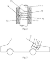
- the vehicle steering wheel assembly may further comprise a steering wheel rotation limiting device 7.
- the steering wheel rotation limiting device 7 comprises a first limiting member 71 and a second limiting member 72.
- the first limiting member 71 is slidably mounted on the steering column 5, and the first limiting member 71 is movable along the axial direction of the steering column 5 with the rotation of the steering wheel 1.
- the second limiting member 72 is disposed on the steering column 5, and the upper end and the lower end of the second limiting member 72 are respectively provided with a stopping portion 721 and 722, and the stopping portions 721 and 722 are respectively positioned above and below the first limiting member 71.
- the first limiting member 71 abuts against the stopping portion 721 of the upper end of the second limiting member 72 or the stopping portion 722 of the lower end thereof, and the rotation of the steering wheel 1 is restricted.
- the first limiting member 71 is a limiting block movable along the axial direction of the steering column 5
- the second limiting member 72 is a spiral groove with a preset number of circles which is provided on the outer cylindrical surface of the steering column 5 and sets the axis of the steering column 5 as its axis, wherein one end of the limiting block is slidable in the spiral groove, and the start portion and the end portion of the spiral groove are the two stopping portions 721 and 722 of the second limiting member 72.
- the steering wheel rotation limiting device 7 further comprises a limiting sleeve 73, wherein the limiting sleeve 73 is fixed on the vehicle body 6 of the vehicle and is sleeved on the steering column 5, and the inner wall of the limiting sleeve 73 is provided with a sliding groove 731 for accommodating the axial movement of the other end of the limiting block.
- the spiral groove may be directly machined on the surface of the steering column, or an externally threaded sleeve may be additionally installed.
- both ends of the limiting block are respectively located in the middle position of the spiral groove and the sliding groove 731.
- the steering wheel 1 drives the steering column 5 to rotate to the same side, and the spiral groove on the steering column 5 drives one end of the limiting block to move upward or downward along the axial direction of the steering column 5, while the other end of the limiting block moves in the same direction in the sliding groove 731.
- the limiting block moves to abut the stopping portion 721 of the upper end of the spiral groove or the stopping portion 722 of the lower end thereof, the steering column 5 is prevented from continuing to rotate, thereby functioning as a limit.
- the moving direction of the limiting block is determined according to the rotation direction of the spiral groove. For example, in the present embodiment, the left turn (i.e., counterclockwise rotation) of the steering wheel 1 drives the steering column 5 to rotate to the left, and the spiral groove drives the limit block to moved upwards.
- the shape of the limiting block just like a transverse Chinese character " ".
- the end sliding in the spiral groove is trapezoidal, and the other end sliding in the sliding groove 731 is rectangular, and the limiting block moves in the axial direction of the steering column 5.
- the height of the trapezoid is smaller than the height of the rectangle, and a step is formed at the junction of the two, so that the left and right positions of the limiting block can be restricted to avoid jamming; it can be understood that other shapes are also possible, such as a wedge shape or a truncated cone shape, and it is also possible to be a rectangular shape or a cylindrical shape, and provide a positioning pin or the like in the middle.
- the shape and position of the limiting structure of the steering wheel rotation limiting device 7 are not limited in the embodiment of the present invention.
- the two stopping portions 721 and 722 are respectively disposed at upper and lower ends of the spiral groove, but in other embodiments, the two stopping portions 721, 722 may be respectively disposed at upper and lower ends of the sliding groove 731.
- the spiral groove is disposed on the steering column 5, and the sliding groove 731 is disposed in the limiting sleeve 73, but in other embodiments, the spiral groove may be disposed in the limiting sleeve 73, and the sliding groove 731 is disposed on the steering column 5.
- the object of providing the rotation limiting device in the embodiment of the present invention is to avoid the problem that there is no limitation on the rotation angle of the steering wheel due to the elimination of the mechanical structure. If the rotation angle of the steering wheel is too large, so that the rotation angle of the wheel is too large, for example, if the rotation angle of the wheel exceeds 90 degrees, the vehicle will turn in the opposite direction, causing confusion.
- the steering wheel rotation limiting device 7 is disposed along the circumferential direction of the steering column 5. Compared with the gear and pinion limit manner in the prior design, the steering wheel rotation limiting device of the embodiment of the present invention occupies smaller space, thereby further reducing the space occupied by the steering wheel assembly.
- a vehicle is further provided in an embodiment of the present invention.
- the vehicle includes a vehicle body 6 and the vehicle steering wheel assembly according to Embodiment 1.
- the steering column 5 is rotatably mounted to the vehicle body 6, and the road sense simulator 3 is fixed to the vehicle body 6.
- the control component 4 is an electronic control unit (ECU).
- ECU is also called “driving computer”, “on-board computer”, etc., which is a vehicle-specific microcomputer controller for use.
- the ECU is composed of a microprocessor (CPU), a memory (ROM and RAM), an input/output interface (I/O), an analog-to-digital converter (A/D), and a large-scale integrated circuit such as wave shaping, driver, etc. In this way, it is not necessary to separately provide control components on the vehicle steering wheel assembly, so that the structure is simplified and the cost is saved.
- the control component 4 can also be an independent control component separately provided on the vehicle steering wheel assembly, rather than an ECU.
- the vehicle of the embodiment of the present invention is mainly a four-wheeled vehicle, typically such as a car.
- the vehicle of the embodiment of the invention eliminates the mechanically connected steering system, and instead uses the steer-by-wire steering system and the vehicle steering wheel assembly according to Embodiment 1, so that the vehicle is lighter and the structure is simpler, thereby enabling the steering of the vehicle to be faster and more flexible to meet the requirements of vehicle intelligence.
Landscapes
- Engineering & Computer Science (AREA)
- Chemical & Material Sciences (AREA)
- Combustion & Propulsion (AREA)
- Transportation (AREA)
- Mechanical Engineering (AREA)
- Power Steering Mechanism (AREA)
- Steering Control In Accordance With Driving Conditions (AREA)
Claims (10)
- Un ensemble de volant du véhicule, comprenant un volant (1), un composant de commande (4), un composant de mesure de rotation (2) pour mesurer l'état de rotation du volant (1) et un simulateur de détection de route (3) pour appliquer un couple de résistance à la rotation du volant (1) selon l'état de rotation du volant (1); une colonne de direction (5) est disposée sous le volant (1), dans laquelle l'extrémité supérieure de la colonne de direction (5) est reliée au volant (1), et l'extrémité inférieure de la colonne de direction (5) est connectée au simulateur de détection de route (3), et le simulateur de détection de route (3) est fixé à la carrosserie (6) du véhicule;
le composant de mesure de rotation (2) et le simulateur de détection de route (3) sont tous deux connectés au composant de commande (4), et le composant de commande (4) commande le simulateur de détection de route (3) pour appliquer le couple de résistance à la rotation de le volant (1) selon les données de mesure du composant de mesure de rotation (2), dans lequel le composant de commande (4) est configuré pour envoyer une commande de direction aux mécanismes de direction des roues pour exécuter la direction selon la condition de rotation reçue du volant (1), caractérisé en ce que le composant de commande est configuré pour recevoir la résistance réelle à la rotation de la roue au moment du braquage, et dans lequel le composant de commande (4) est configuré pour transmettre un signal de commande au simulateur de détection de route (3) en fonction de la résistance réelle à la rotation des roues, et dans lequel le simulateur de détection de route (3) est configuré pour appliquer un couple de résistance à la rotation du volant (1) selon le signal de commande reçu. - L'ensemble de volant du véhicule selon la revendication 1, dans lequel le simulateur de détection de route (3) comprend un moteur (31), dans lequel l'extrémité inférieure de la colonne de direction (5) est reliée à l'arbre de sortie du moteur (31), et la colonne de direction (5) et l'arbre de sortie du moteur tournent coaxialement; et le carter du moteur (31) est fixé à la carrosserie (6) du véhicule, et le couple de sortie du moteur (31) est le couple résistant appliqué à la rotation du volant (1) par le simulateur de détection de route (3).
- L'ensemble de volant du véhicule selon la revendication 2, dans lequel l'élément de mesure de rotation est un codeur, et le codeur comprend une partie de fixation et une partie de mesure, dans laquelle la partie de fixation est fixée à l'extrémité supérieure du carter du moteur (31), et la partie de mesure est emmanché sur l'arbre de sortie.
- L'ensemble de volant du véhicule selon la revendication 2, dans lequel le simulateur de détection de route (3) comprend en outre un contrôleur de moteur (32), dans lequel le contrôleur de moteur (32) est fixé au carter du moteur (31), et le contrôleur de moteur (32) reçoit un signal de commande du composant de commande (4) et contrôle le couple de sortie du moteur (31) selon le signal de commande.
- L'ensemble de volant du véhicule selon la revendication 1, dans lequel l'ensemble volant du véhicule comprend en outre un dispositif de limitation de rotation du volant (7), dans lequel le dispositif de limitation de rotation du volant (7) comprend un premier élément de limitation (71) et un deuxième élément de limitation (72); le premier élément de limitation (71) est monté de manière coulissante sur la colonne de direction (5) et le premier élément de limitation (71) est mobile le long de la direction axiale de la colonne de direction (5) avec la rotation du volant (1); le deuxième élément de limitation (72) est disposé sur la colonne de direction (5), et l'extrémité supérieure et l'extrémité inférieure du deuxième élément limite (72) sont respectivement munies d'une partie d'arrêt, et les parties d'arrêt sont respectivement positionnées au-dessus et au-dessous du premier élément de limitation (71), dans lequel, après que le volant (1) est tourné par un angle prédéterminé, le premier élément de limitation (71) vient en butée contre la partie d'arrêt de l'extrémité supérieure ou de l'extrémité inférieure du deuxième élément de limitation (72), et la rotation du volant (1) est limitée.
- L'ensemble de volant du véhicule selon la revendication 5, dans lequel le premier élément de limitation (71) est un bloc de limitation mobile le long de la direction axiale de la colonne de direction (5), et le deuxième élément de limitation (72) est une rainure en spirale avec un préréglage nombre de cercles qui est prévu sur la surface cylindrique externe de la colonne de direction (5) et régler l'axe de la colonne de direction (5) par rapport à son axe, dans lequel une extrémité du bloc de limitation peut coulisser dans la rainure en spirale, et le partie de départ et la partie terminal de la rainure en spirale sont les deux portions d'arrêt du deuxième élément de limitation (72); et le dispositif de limitation de rotation du volant (7) comprend en outre un manchon de limitation (73), dans lequel le manchon de limitation (73) est fixé sur la carrosserie (6) de véhicule et est emmanché sur la colonne de direction (5), et la paroi interne du manchon de limitation (73) est pourvue d'une rainure de coulissement pour permettre le mouvement axial de l'autre extrémité du bloc de limitation.
- Un véhicule est caractérisé en ce que le véhicule comprend une carrosserie du véhicule (6) et l'ensemble de volant du véhicule selon la revendication 1; la colonne de direction (5) est montée rotative sur la carrosserie du véhicule (6), et le simulateur de détection de route (3) est fixé sur la carrosserie du véhicule (6); et le composant de commande (4) est une unité de commande électronique.
- Le véhicule selon la revendication 7, dans lequel le simulateur de détection de route (3) comprend un moteur (31), dans lequel l'extrémité inférieure de la colonne de direction (5) est reliée à l'arbre de sortie du moteur (31), et la colonne de direction (5) et l'arbre de sortie tournent coaxialement; et le carter du moteur (31) est fixé à la carrosserie du véhicule (6), et le couple de sortie du moteur (31) est le couple résistant appliqué à la rotation du volant (1) par le simulateur de détection de route (3).
- Le véhicule selon la revendication 8, dans lequel l'élément de mesure de rotation est un codeur, dans lequel le codeur comprend une partie de fixation et une partie de mesure, la partie de fixation est fixée à l'extrémité supérieure du carter du moteur (31), et la partie de mesure est emmanchée sur l'arbre de sortie.
- Le véhicule selon la revendication 7, dans lequel l'ensemble de volant comprend en outre un dispositif de limitation de rotation du volant (7), dans lequel le dispositif de limitation de rotation du volant (7) comprend un premier élément de limitation (71) et un deuxième élément de limitation (72); le premier élément de limitation (71) est monté de manière coulissant sur la colonne de direction (5), et le premier élément de limitation (71) est mobile le long de la direction axiale de la colonne de direction (5) avec la rotation du volant (1); le deuxième élément de limitation (72) est disposé sur la colonne de direction (5), et l'extrémité supérieure et l'extrémité inférieure du deuxième élément de limitation (72) sont respectivement pourvues d'une partie d'arrêt, et les parties d'arrêt sont respectivement positionnées au-dessus et sous le premier élément de limitation (71), dans lequel, après que le volant (1) a été tourné d'un angle prédéterminé, le premier élément de limitation (71) vient en butée contre contre la partie d'arrêt de l'extrémité supérieure ou de l'extrémité inférieure du deuxième élément de limitation (72), et la rotation du volant (1) est limitée.
Applications Claiming Priority (1)
| Application Number | Priority Date | Filing Date | Title |
|---|---|---|---|
| CN201811032330.3A CN108909820A (zh) | 2018-09-05 | 2018-09-05 | 一种汽车方向盘总成及汽车 |
Publications (2)
| Publication Number | Publication Date |
|---|---|
| EP3620350A1 EP3620350A1 (fr) | 2020-03-11 |
| EP3620350B1 true EP3620350B1 (fr) | 2022-07-13 |
Family
ID=64407564
Family Applications (1)
| Application Number | Title | Priority Date | Filing Date |
|---|---|---|---|
| EP19194852.0A Active EP3620350B1 (fr) | 2018-09-05 | 2019-09-02 | Ensemble de volant de direction de véhicule et véhicule |
Country Status (4)
| Country | Link |
|---|---|
| US (1) | US20200070871A1 (fr) |
| EP (1) | EP3620350B1 (fr) |
| CN (1) | CN108909820A (fr) |
| MA (1) | MA47478B1 (fr) |
Families Citing this family (28)
| Publication number | Priority date | Publication date | Assignee | Title |
|---|---|---|---|---|
| IT201700121893A1 (it) * | 2017-10-26 | 2019-04-26 | Ferrari Spa | "sistema di sterzatura di un veicolo stradale di tipo "steer by wire" e provvisto di un dispositivo di fine corsa meccanico per il volante" |
| IT201700121876A1 (it) * | 2017-10-26 | 2019-04-26 | Ferrari Spa | "sistema di sterzatura di un veicolo stradale di tipo "steer by wire" e provvisto di un elemento di supporto telescopico per il volante" |
| CN112477974A (zh) * | 2019-09-12 | 2021-03-12 | 比亚迪股份有限公司 | 车辆及其转向组件 |
| CN112706827B (zh) * | 2019-10-25 | 2022-07-15 | 比亚迪股份有限公司 | 转向系统、轴套和汽车 |
| US11724737B2 (en) * | 2020-05-08 | 2023-08-15 | Caterpillar Inc. | Hybrid steering system and method implementing virtual and mechanical stops |
| CN113879388A (zh) * | 2020-07-03 | 2022-01-04 | 宝能汽车集团有限公司 | 用于车辆的方向盘组件及具有其的车辆 |
| FR3113021A1 (fr) * | 2020-07-28 | 2022-02-04 | Jtekt Europe | Système de direction pour véhicule |
| CN111942458A (zh) * | 2020-08-12 | 2020-11-17 | 内蒙古第一机械集团股份有限公司 | 适用于轮式车辆线控转向系统的方向盘转角限位装置 |
| EP3960582B1 (fr) | 2020-08-28 | 2023-09-27 | Lotus Tech Innovation Centre GmbH | Système de direction à commande électrique comprenant un dispositif de rétroaction de couple de rotor externe |
| EP3960585B1 (fr) * | 2020-08-28 | 2023-09-27 | Lotus Tech Innovation Centre GmbH | Système de direction par câbles comprenant un dispositif de limitation de rotation de volant de direction |
| EP4275992A3 (fr) | 2020-08-28 | 2024-02-21 | Lotus Tech Innovation Centre GmbH | Système de direction par câbles doté d'une colonne support de système de direction hors-axe |
| EP3960584B1 (fr) | 2020-08-28 | 2023-02-08 | Lotus Tech Innovation Centre GmbH | Système de direction à commande électrique ayant une colonne de support de système de direction hors axe munie d'un dispositif de limitation de rotation du volant |
| CN114684250B (zh) * | 2020-12-30 | 2023-11-14 | 比亚迪股份有限公司 | 车辆转向系统和具有其的车辆 |
| CN116917187A (zh) | 2021-02-22 | 2023-10-20 | 海拉有限双合股份公司 | 旋转角度传感器布置结构和用于车辆的转向系统 |
| DE102021201640A1 (de) * | 2021-02-22 | 2022-08-25 | Thyssenkrupp Ag | Lenksäule für ein Kraftfahrzeug |
| CN113071561B (zh) * | 2021-03-24 | 2022-07-05 | 浙江合众新能源汽车有限公司 | 一种方向盘转向指示识别可视系统 |
| DE102021003660A1 (de) * | 2021-07-09 | 2023-01-12 | Schaeffler Technologies AG & Co. KG | Verstelleinrichtung für Lenksäulen von Fahrzeugen |
| KR102906017B1 (ko) * | 2021-08-02 | 2025-12-30 | 에이치엘만도 주식회사 | 스티어 바이 와이어식 조향장치 |
| DE102021123383B3 (de) * | 2021-09-09 | 2022-12-22 | Schaeffler Technologies AG & Co. KG | Lenkereinheit für ein Steer-by-wire-Lenksystem eines Kraftfahrzeugs |
| US20240067255A1 (en) * | 2022-08-31 | 2024-02-29 | Steering Solutions Ip Holding Corporation | Steer-by-wire road wheel actuator multi-groove ball screw anti-rotation mechanism |
| US20240140523A1 (en) * | 2022-08-31 | 2024-05-02 | Steering Solutions Ip Holding Corporation | Steer-by-wire road wheel actuator multi-groove ball screw anti-rotation mechanism |
| GB2628431A (en) * | 2023-03-20 | 2024-09-25 | Zf Steering Systems Poland Sp Z O O | A steering assembly for a vehicle |
| CN116691831B (zh) * | 2023-04-17 | 2025-08-15 | 杭州电子科技大学 | 一种具有冗余安全装置的方向盘转角检测装置 |
| SE546934C2 (en) * | 2023-05-25 | 2025-03-11 | Chassis Autonomy Sba Ab | Handwheel actuator and steering wheel armature assembly for a steer-by-wire steering assembly |
| CN116811553A (zh) * | 2023-07-19 | 2023-09-29 | 华侨大学 | 一种四轮独立驱动系统及轮式车辆 |
| BE1031866B1 (de) | 2023-08-04 | 2025-03-04 | Thyssenkrupp Presta Ag | Lenksäule für ein Kraftfahrzeug |
| KR20250070853A (ko) * | 2023-11-14 | 2025-05-21 | 현대모비스 주식회사 | 차량용 조향장치 |
| DE102024102468B3 (de) * | 2024-01-29 | 2024-06-20 | Thyssenkrupp Ag | Lenksäule für ein Kraftfahrzeug |
Family Cites Families (11)
| Publication number | Priority date | Publication date | Assignee | Title |
|---|---|---|---|---|
| DE10157797A1 (de) * | 2000-11-29 | 2002-09-19 | Continental Teves Ag & Co Ohg | Simulatoreinheit für ein Lenkrad einer Fahrzeuglenkung |
| US6896089B2 (en) * | 2002-02-05 | 2005-05-24 | Ford Global Technologies, Llc | Steer-by-wire steering system with rotation limiter |
| KR20030084303A (ko) * | 2002-04-26 | 2003-11-01 | 주식회사 메카테크 | 회전축 회전제한장치 |
| US6899196B2 (en) * | 2003-10-16 | 2005-05-31 | Visteon Global Technologies, Inc. | Driver interface system for steer-by-wire system |
| JP4604566B2 (ja) * | 2004-06-17 | 2011-01-05 | 日産自動車株式会社 | 車両用操舵装置 |
| JP5979408B2 (ja) * | 2012-02-28 | 2016-08-24 | 株式会社ジェイテクト | 車両用操舵装置 |
| CN103419835B (zh) * | 2013-07-22 | 2015-12-23 | 湖南大学 | 一种汽车线控转向系统及其控制方法 |
| US10160477B2 (en) * | 2016-08-01 | 2018-12-25 | Steering Solutions Ip Holding Corporation | Electric power steering column assembly |
| CN206243238U (zh) * | 2016-12-16 | 2017-06-13 | 吉林大学 | 双转子电机线控转向系统及其失效防护装置 |
| CN107284516A (zh) * | 2017-03-30 | 2017-10-24 | 吉林大学 | 一种具有可调限位及回正的力触觉引导辅助转向装置 |
| CN208698854U (zh) * | 2018-09-05 | 2019-04-05 | 中信戴卡股份有限公司 | 一种汽车方向盘总成及汽车 |
-
2018
- 2018-09-05 CN CN201811032330.3A patent/CN108909820A/zh not_active Withdrawn
-
2019
- 2019-04-22 US US16/390,107 patent/US20200070871A1/en not_active Abandoned
- 2019-09-02 EP EP19194852.0A patent/EP3620350B1/fr active Active
- 2019-09-02 MA MA47478A patent/MA47478B1/fr unknown
Also Published As
| Publication number | Publication date |
|---|---|
| CN108909820A (zh) | 2018-11-30 |
| EP3620350A1 (fr) | 2020-03-11 |
| US20200070871A1 (en) | 2020-03-05 |
| MA47478B1 (fr) | 2022-09-30 |
Similar Documents
| Publication | Publication Date | Title |
|---|---|---|
| EP3620350B1 (fr) | Ensemble de volant de direction de véhicule et véhicule | |
| US11945519B2 (en) | Reaction force generating device and steering device | |
| US12454311B2 (en) | Steer-by-wire steering device and method for controlling the same | |
| US12473009B2 (en) | Steer by wire type steering apparatus | |
| CN115805990A (zh) | 电动转向设备 | |
| KR102693164B1 (ko) | 스티어 바이 와이어식 조향장치 | |
| GB2211156A (en) | Power steering apparatus | |
| CN110861703A (zh) | 转向控制设备 | |
| US20200070878A1 (en) | Vehicle steering control system, vehicle and control method | |
| CN113135224A (zh) | 一种线控转向路感模拟控制系统 | |
| CN217672801U (zh) | 转向管柱、车辆转向系统和车辆 | |
| US20230040073A1 (en) | Steer by wire type steering apparatus | |
| CN109923025A (zh) | 用于机动车辆的具有蜗轮蜗杆传动机构的齿轮齿条式转向系统 | |
| CN208698854U (zh) | 一种汽车方向盘总成及汽车 | |
| EP1571063B1 (fr) | Appareil de direction | |
| KR102109341B1 (ko) | 전동식 동력 보조 조향장치 | |
| US12195078B2 (en) | Vehicle steering column | |
| KR102589735B1 (ko) | 스티어 바이 와이어식 조향장치 | |
| CN117068254B (zh) | 一种冗余设计的汽车转向系统、控制方法及车辆 | |
| US20230045603A1 (en) | Electric power steering apparatus | |
| CN215904585U (zh) | 一种线控转向管柱、线控转向系统及汽车 | |
| KR20240024000A (ko) | 스티어 바이 와이어식 조향장치 | |
| JP4114560B2 (ja) | 電動パワーステアリング装置 | |
| CN111942458A (zh) | 适用于轮式车辆线控转向系统的方向盘转角限位装置 | |
| KR102858583B1 (ko) | 전동식 동력 보조 조향장치 |
Legal Events
| Date | Code | Title | Description |
|---|---|---|---|
| PUAI | Public reference made under article 153(3) epc to a published international application that has entered the european phase |
Free format text: ORIGINAL CODE: 0009012 |
|
| STAA | Information on the status of an ep patent application or granted ep patent |
Free format text: STATUS: REQUEST FOR EXAMINATION WAS MADE |
|
| 17P | Request for examination filed |
Effective date: 20190902 |
|
| AK | Designated contracting states |
Kind code of ref document: A1 Designated state(s): AL AT BE BG CH CY CZ DE DK EE ES FI FR GB GR HR HU IE IS IT LI LT LU LV MC MK MT NL NO PL PT RO RS SE SI SK SM TR |
|
| AX | Request for extension of the european patent |
Extension state: BA ME |
|
| GRAP | Despatch of communication of intention to grant a patent |
Free format text: ORIGINAL CODE: EPIDOSNIGR1 |
|
| STAA | Information on the status of an ep patent application or granted ep patent |
Free format text: STATUS: GRANT OF PATENT IS INTENDED |
|
| GRAS | Grant fee paid |
Free format text: ORIGINAL CODE: EPIDOSNIGR3 |
|
| INTG | Intention to grant announced |
Effective date: 20220128 |
|
| GRAF | Information related to payment of grant fee modified |
Free format text: ORIGINAL CODE: EPIDOSCIGR3 |
|
| GRAA | (expected) grant |
Free format text: ORIGINAL CODE: 0009210 |
|
| STAA | Information on the status of an ep patent application or granted ep patent |
Free format text: STATUS: THE PATENT HAS BEEN GRANTED |
|
| AK | Designated contracting states |
Kind code of ref document: B1 Designated state(s): AL AT BE BG CH CY CZ DE DK EE ES FI FR GB GR HR HU IE IS IT LI LT LU LV MC MK MT NL NO PL PT RO RS SE SI SK SM TR |
|
| REG | Reference to a national code |
Ref country code: CH Ref legal event code: EP |
|
| REG | Reference to a national code |
Ref country code: DE Ref legal event code: R096 Ref document number: 602019016918 Country of ref document: DE |
|
| REG | Reference to a national code |
Ref country code: AT Ref legal event code: REF Ref document number: 1504141 Country of ref document: AT Kind code of ref document: T Effective date: 20220815 |
|
| REG | Reference to a national code |
Ref country code: IE Ref legal event code: FG4D |
|
| REG | Reference to a national code |
Ref country code: MA Ref legal event code: VAGR Ref document number: 47478 Country of ref document: MA Kind code of ref document: B1 |
|
| REG | Reference to a national code |
Ref country code: LT Ref legal event code: MG9D |
|
| REG | Reference to a national code |
Ref country code: NL Ref legal event code: MP Effective date: 20220713 |
|
| PG25 | Lapsed in a contracting state [announced via postgrant information from national office to epo] |
Ref country code: SE Free format text: LAPSE BECAUSE OF FAILURE TO SUBMIT A TRANSLATION OF THE DESCRIPTION OR TO PAY THE FEE WITHIN THE PRESCRIBED TIME-LIMIT Effective date: 20220713 Ref country code: RS Free format text: LAPSE BECAUSE OF FAILURE TO SUBMIT A TRANSLATION OF THE DESCRIPTION OR TO PAY THE FEE WITHIN THE PRESCRIBED TIME-LIMIT Effective date: 20220713 Ref country code: PT Free format text: LAPSE BECAUSE OF FAILURE TO SUBMIT A TRANSLATION OF THE DESCRIPTION OR TO PAY THE FEE WITHIN THE PRESCRIBED TIME-LIMIT Effective date: 20221114 Ref country code: NO Free format text: LAPSE BECAUSE OF FAILURE TO SUBMIT A TRANSLATION OF THE DESCRIPTION OR TO PAY THE FEE WITHIN THE PRESCRIBED TIME-LIMIT Effective date: 20221013 Ref country code: NL Free format text: LAPSE BECAUSE OF FAILURE TO SUBMIT A TRANSLATION OF THE DESCRIPTION OR TO PAY THE FEE WITHIN THE PRESCRIBED TIME-LIMIT Effective date: 20220713 Ref country code: LV Free format text: LAPSE BECAUSE OF FAILURE TO SUBMIT A TRANSLATION OF THE DESCRIPTION OR TO PAY THE FEE WITHIN THE PRESCRIBED TIME-LIMIT Effective date: 20220713 Ref country code: LT Free format text: LAPSE BECAUSE OF FAILURE TO SUBMIT A TRANSLATION OF THE DESCRIPTION OR TO PAY THE FEE WITHIN THE PRESCRIBED TIME-LIMIT Effective date: 20220713 Ref country code: FI Free format text: LAPSE BECAUSE OF FAILURE TO SUBMIT A TRANSLATION OF THE DESCRIPTION OR TO PAY THE FEE WITHIN THE PRESCRIBED TIME-LIMIT Effective date: 20220713 Ref country code: ES Free format text: LAPSE BECAUSE OF FAILURE TO SUBMIT A TRANSLATION OF THE DESCRIPTION OR TO PAY THE FEE WITHIN THE PRESCRIBED TIME-LIMIT Effective date: 20220713 |
|
| REG | Reference to a national code |
Ref country code: AT Ref legal event code: MK05 Ref document number: 1504141 Country of ref document: AT Kind code of ref document: T Effective date: 20220713 |
|
| PG25 | Lapsed in a contracting state [announced via postgrant information from national office to epo] |
Ref country code: PL Free format text: LAPSE BECAUSE OF FAILURE TO SUBMIT A TRANSLATION OF THE DESCRIPTION OR TO PAY THE FEE WITHIN THE PRESCRIBED TIME-LIMIT Effective date: 20220713 Ref country code: IS Free format text: LAPSE BECAUSE OF FAILURE TO SUBMIT A TRANSLATION OF THE DESCRIPTION OR TO PAY THE FEE WITHIN THE PRESCRIBED TIME-LIMIT Effective date: 20221113 Ref country code: HR Free format text: LAPSE BECAUSE OF FAILURE TO SUBMIT A TRANSLATION OF THE DESCRIPTION OR TO PAY THE FEE WITHIN THE PRESCRIBED TIME-LIMIT Effective date: 20220713 Ref country code: GR Free format text: LAPSE BECAUSE OF FAILURE TO SUBMIT A TRANSLATION OF THE DESCRIPTION OR TO PAY THE FEE WITHIN THE PRESCRIBED TIME-LIMIT Effective date: 20221014 |
|
| REG | Reference to a national code |
Ref country code: DE Ref legal event code: R097 Ref document number: 602019016918 Country of ref document: DE |
|
| PG25 | Lapsed in a contracting state [announced via postgrant information from national office to epo] |
Ref country code: SM Free format text: LAPSE BECAUSE OF FAILURE TO SUBMIT A TRANSLATION OF THE DESCRIPTION OR TO PAY THE FEE WITHIN THE PRESCRIBED TIME-LIMIT Effective date: 20220713 Ref country code: RO Free format text: LAPSE BECAUSE OF FAILURE TO SUBMIT A TRANSLATION OF THE DESCRIPTION OR TO PAY THE FEE WITHIN THE PRESCRIBED TIME-LIMIT Effective date: 20220713 Ref country code: MC Free format text: LAPSE BECAUSE OF FAILURE TO SUBMIT A TRANSLATION OF THE DESCRIPTION OR TO PAY THE FEE WITHIN THE PRESCRIBED TIME-LIMIT Effective date: 20220713 Ref country code: DK Free format text: LAPSE BECAUSE OF FAILURE TO SUBMIT A TRANSLATION OF THE DESCRIPTION OR TO PAY THE FEE WITHIN THE PRESCRIBED TIME-LIMIT Effective date: 20220713 Ref country code: CZ Free format text: LAPSE BECAUSE OF FAILURE TO SUBMIT A TRANSLATION OF THE DESCRIPTION OR TO PAY THE FEE WITHIN THE PRESCRIBED TIME-LIMIT Effective date: 20220713 Ref country code: AT Free format text: LAPSE BECAUSE OF FAILURE TO SUBMIT A TRANSLATION OF THE DESCRIPTION OR TO PAY THE FEE WITHIN THE PRESCRIBED TIME-LIMIT Effective date: 20220713 |
|
| REG | Reference to a national code |
Ref country code: CH Ref legal event code: PL |
|
| PLBE | No opposition filed within time limit |
Free format text: ORIGINAL CODE: 0009261 |
|
| STAA | Information on the status of an ep patent application or granted ep patent |
Free format text: STATUS: NO OPPOSITION FILED WITHIN TIME LIMIT |
|
| REG | Reference to a national code |
Ref country code: BE Ref legal event code: MM Effective date: 20220930 |
|
| PG25 | Lapsed in a contracting state [announced via postgrant information from national office to epo] |
Ref country code: SK Free format text: LAPSE BECAUSE OF FAILURE TO SUBMIT A TRANSLATION OF THE DESCRIPTION OR TO PAY THE FEE WITHIN THE PRESCRIBED TIME-LIMIT Effective date: 20220713 Ref country code: EE Free format text: LAPSE BECAUSE OF FAILURE TO SUBMIT A TRANSLATION OF THE DESCRIPTION OR TO PAY THE FEE WITHIN THE PRESCRIBED TIME-LIMIT Effective date: 20220713 |
|
| 26N | No opposition filed |
Effective date: 20230414 |
|
| PG25 | Lapsed in a contracting state [announced via postgrant information from national office to epo] |
Ref country code: LU Free format text: LAPSE BECAUSE OF NON-PAYMENT OF DUE FEES Effective date: 20220902 Ref country code: AL Free format text: LAPSE BECAUSE OF FAILURE TO SUBMIT A TRANSLATION OF THE DESCRIPTION OR TO PAY THE FEE WITHIN THE PRESCRIBED TIME-LIMIT Effective date: 20220713 |
|
| PG25 | Lapsed in a contracting state [announced via postgrant information from national office to epo] |
Ref country code: LI Free format text: LAPSE BECAUSE OF NON-PAYMENT OF DUE FEES Effective date: 20220930 Ref country code: IE Free format text: LAPSE BECAUSE OF NON-PAYMENT OF DUE FEES Effective date: 20220902 Ref country code: CH Free format text: LAPSE BECAUSE OF NON-PAYMENT OF DUE FEES Effective date: 20220930 |
|
| PG25 | Lapsed in a contracting state [announced via postgrant information from national office to epo] |
Ref country code: SI Free format text: LAPSE BECAUSE OF FAILURE TO SUBMIT A TRANSLATION OF THE DESCRIPTION OR TO PAY THE FEE WITHIN THE PRESCRIBED TIME-LIMIT Effective date: 20220713 |
|
| PG25 | Lapsed in a contracting state [announced via postgrant information from national office to epo] |
Ref country code: BE Free format text: LAPSE BECAUSE OF NON-PAYMENT OF DUE FEES Effective date: 20220930 |
|
| PG25 | Lapsed in a contracting state [announced via postgrant information from national office to epo] |
Ref country code: IT Free format text: LAPSE BECAUSE OF FAILURE TO SUBMIT A TRANSLATION OF THE DESCRIPTION OR TO PAY THE FEE WITHIN THE PRESCRIBED TIME-LIMIT Effective date: 20220713 |
|
| PG25 | Lapsed in a contracting state [announced via postgrant information from national office to epo] |
Ref country code: HU Free format text: LAPSE BECAUSE OF FAILURE TO SUBMIT A TRANSLATION OF THE DESCRIPTION OR TO PAY THE FEE WITHIN THE PRESCRIBED TIME-LIMIT; INVALID AB INITIO Effective date: 20190902 |
|
| PG25 | Lapsed in a contracting state [announced via postgrant information from national office to epo] |
Ref country code: CY Free format text: LAPSE BECAUSE OF FAILURE TO SUBMIT A TRANSLATION OF THE DESCRIPTION OR TO PAY THE FEE WITHIN THE PRESCRIBED TIME-LIMIT Effective date: 20220713 |
|
| GBPC | Gb: european patent ceased through non-payment of renewal fee |
Effective date: 20230902 |
|
| PG25 | Lapsed in a contracting state [announced via postgrant information from national office to epo] |
Ref country code: MK Free format text: LAPSE BECAUSE OF FAILURE TO SUBMIT A TRANSLATION OF THE DESCRIPTION OR TO PAY THE FEE WITHIN THE PRESCRIBED TIME-LIMIT Effective date: 20220713 |
|
| PG25 | Lapsed in a contracting state [announced via postgrant information from national office to epo] |
Ref country code: TR Free format text: LAPSE BECAUSE OF FAILURE TO SUBMIT A TRANSLATION OF THE DESCRIPTION OR TO PAY THE FEE WITHIN THE PRESCRIBED TIME-LIMIT Effective date: 20220713 |
|
| PG25 | Lapsed in a contracting state [announced via postgrant information from national office to epo] |
Ref country code: GB Free format text: LAPSE BECAUSE OF NON-PAYMENT OF DUE FEES Effective date: 20230902 |
|
| PG25 | Lapsed in a contracting state [announced via postgrant information from national office to epo] |
Ref country code: GB Free format text: LAPSE BECAUSE OF NON-PAYMENT OF DUE FEES Effective date: 20230902 Ref country code: BG Free format text: LAPSE BECAUSE OF FAILURE TO SUBMIT A TRANSLATION OF THE DESCRIPTION OR TO PAY THE FEE WITHIN THE PRESCRIBED TIME-LIMIT Effective date: 20220713 |
|
| PG25 | Lapsed in a contracting state [announced via postgrant information from national office to epo] |
Ref country code: MT Free format text: LAPSE BECAUSE OF FAILURE TO SUBMIT A TRANSLATION OF THE DESCRIPTION OR TO PAY THE FEE WITHIN THE PRESCRIBED TIME-LIMIT Effective date: 20220713 |
|
| PGFP | Annual fee paid to national office [announced via postgrant information from national office to epo] |
Ref country code: DE Payment date: 20250916 Year of fee payment: 7 |
|
| PGFP | Annual fee paid to national office [announced via postgrant information from national office to epo] |
Ref country code: FR Payment date: 20250929 Year of fee payment: 7 |
|
| VS25 | Lapsed in a validation state [announced via postgrant information from nat. office to epo] |
Ref country code: MA Free format text: LAPSE BECAUSE OF NON-PAYMENT OF DUE FEES Effective date: 20230903 |
|
| VSFP | Annual fee paid to validation state [announced via postgrant information from national office to epo] |
Ref country code: MA Payment date: 20220902 Year of fee payment: 4 |