EP3620542B1 - Verfahren zur umrichterbetriebsüberwachung und umrichterbetriebsverfahren - Google Patents
Verfahren zur umrichterbetriebsüberwachung und umrichterbetriebsverfahren Download PDFInfo
- Publication number
- EP3620542B1 EP3620542B1 EP18823747.3A EP18823747A EP3620542B1 EP 3620542 B1 EP3620542 B1 EP 3620542B1 EP 18823747 A EP18823747 A EP 18823747A EP 3620542 B1 EP3620542 B1 EP 3620542B1
- Authority
- EP
- European Patent Office
- Prior art keywords
- converter
- emission intensity
- change
- rate
- moving average
- Prior art date
- Legal status (The legal status is an assumption and is not a legal conclusion. Google has not performed a legal analysis and makes no representation as to the accuracy of the status listed.)
- Active
Links
Images


Classifications
-
- C—CHEMISTRY; METALLURGY
- C21—METALLURGY OF IRON
- C21C—PROCESSING OF PIG-IRON, e.g. REFINING, MANUFACTURE OF WROUGHT-IRON OR STEEL; TREATMENT IN MOLTEN STATE OF FERROUS ALLOYS
- C21C5/00—Manufacture of carbon-steel, e.g. plain mild steel, medium carbon steel or cast steel or stainless steel
- C21C5/28—Manufacture of steel in the converter
- C21C5/42—Constructional features of converters
- C21C5/46—Details or accessories
- C21C5/4673—Measuring and sampling devices
-
- C—CHEMISTRY; METALLURGY
- C21—METALLURGY OF IRON
- C21C—PROCESSING OF PIG-IRON, e.g. REFINING, MANUFACTURE OF WROUGHT-IRON OR STEEL; TREATMENT IN MOLTEN STATE OF FERROUS ALLOYS
- C21C5/00—Manufacture of carbon-steel, e.g. plain mild steel, medium carbon steel or cast steel or stainless steel
- C21C5/28—Manufacture of steel in the converter
- C21C5/30—Regulating or controlling the blowing
-
- F—MECHANICAL ENGINEERING; LIGHTING; HEATING; WEAPONS; BLASTING
- F27—FURNACES; KILNS; OVENS; RETORTS
- F27D—DETAILS OR ACCESSORIES OF FURNACES, KILNS, OVENS OR RETORTS, IN SO FAR AS THEY ARE OF KINDS OCCURRING IN MORE THAN ONE KIND OF FURNACE
- F27D21/00—Arrangement of monitoring devices; Arrangement of safety devices
-
- F—MECHANICAL ENGINEERING; LIGHTING; HEATING; WEAPONS; BLASTING
- F27—FURNACES; KILNS; OVENS; RETORTS
- F27D—DETAILS OR ACCESSORIES OF FURNACES, KILNS, OVENS OR RETORTS, IN SO FAR AS THEY ARE OF KINDS OCCURRING IN MORE THAN ONE KIND OF FURNACE
- F27D21/00—Arrangement of monitoring devices; Arrangement of safety devices
- F27D21/02—Observation or illuminating devices
-
- F—MECHANICAL ENGINEERING; LIGHTING; HEATING; WEAPONS; BLASTING
- F27—FURNACES; KILNS; OVENS; RETORTS
- F27D—DETAILS OR ACCESSORIES OF FURNACES, KILNS, OVENS OR RETORTS, IN SO FAR AS THEY ARE OF KINDS OCCURRING IN MORE THAN ONE KIND OF FURNACE
- F27D19/00—Arrangements of controlling devices
- F27D2019/0028—Regulation
- F27D2019/0034—Regulation through control of a heating quantity such as fuel, oxidant or intensity of current
-
- F—MECHANICAL ENGINEERING; LIGHTING; HEATING; WEAPONS; BLASTING
- F27—FURNACES; KILNS; OVENS; RETORTS
- F27D—DETAILS OR ACCESSORIES OF FURNACES, KILNS, OVENS OR RETORTS, IN SO FAR AS THEY ARE OF KINDS OCCURRING IN MORE THAN ONE KIND OF FURNACE
- F27D21/00—Arrangement of monitoring devices; Arrangement of safety devices
- F27D21/02—Observation or illuminating devices
- F27D2021/026—Observation or illuminating devices using a video installation
-
- Y—GENERAL TAGGING OF NEW TECHNOLOGICAL DEVELOPMENTS; GENERAL TAGGING OF CROSS-SECTIONAL TECHNOLOGIES SPANNING OVER SEVERAL SECTIONS OF THE IPC; TECHNICAL SUBJECTS COVERED BY FORMER USPC CROSS-REFERENCE ART COLLECTIONS [XRACs] AND DIGESTS
- Y02—TECHNOLOGIES OR APPLICATIONS FOR MITIGATION OR ADAPTATION AGAINST CLIMATE CHANGE
- Y02P—CLIMATE CHANGE MITIGATION TECHNOLOGIES IN THE PRODUCTION OR PROCESSING OF GOODS
- Y02P10/00—Technologies related to metal processing
- Y02P10/20—Recycling
Definitions
- the present invention relates to a method for monitoring the operation of a converter in which hot metal in the converter is subjected to oxidation refining by blowing an oxidizing gas on the hot metal from a top blowing lance, and a method for operating a converter, and more particularly to a method for monitoring an operation and an operation method that contribute to improvements in productivity and the yield of iron.
- Molten pig iron produced in blast furnaces contains impurities such as carbon (C), phosphorus (P), and silicon (Si).
- impurities such as carbon (C), phosphorus (P), and silicon (Si).
- hot metal is subjected to oxidation refinement by blowing an oxidizing gas on the surface of hot metal or by blowing an oxidizing gas into hot metal. Thereby, molten steel is produced from the hot metal.
- a decarburization reaction C + O ⁇ CO
- a desiliconization reaction Si + 2O ⁇ SiO 2
- the desiliconization reaction occurs preferentially. After silicon concentration in the hot metal is reduced by the desiliconization reaction, the decarburization reaction and the dephosphorization reaction occur.
- the early period of the refining where the desiliconization reaction occurs mainly is referred to as a "desiliconization period”
- the period where the subsequent decarburization reaction and dephosphorization reaction occur is referred to as a "decarburization period” or "dephosphorizationdecarburization period”.
- the decarburization reaction and the dephosphorization reaction do not occur entirely during the desiliconization period. Although the reaction rate is slow, the decarburization reaction and the dephosphorization reaction also occur.
- oxidation refining also referred to as "decarburization refining”
- decarburization refining hot metal changes to molten steel as the decarburization reaction proceeds.
- hot metal and molten steel are scarcely distinguishable from each other or displayed separately.
- hot metal and molten steel are collectively referred to as "molten iron”.
- oxygen blowing should be interrupted, thereby decreasing the productivity.
- oxygen blowing indicates desiliconization treatment, dephosphorization treatment, and decarburization treatment performed by blowing an oxidizing gas from a top blowing lance.
- Patent Literature 1 discloses a top blowing lance in which a hot-spot-overlapping ratio (d/D) defined by the ratio of an overlapping portion d between the hot spot and a hot spot adjacent to the hot spot to the diameter D of a high-temperature reaction region (referred to as a "hot spot” or "cavity”) formed on a collision surface between top-blown oxygen gas and molten iron is 0.2 or less.
- d/D hot-spot-overlapping ratio
- Patent Literature 2 discloses a refining method with a converter in which a seven-hole lance including a central hole and its surrounding six holes is used, the outermost position of hot spots is separated by 0.4 m or more from the refractory position of a converter wall, hot-spot-overlap percentage is 30% or less of the total area of the hot spots, and the total area of the hot spots is 75% or more of the area of a circle surrounding the outermost circumference of the hot spots.
- Patent Literature 2 states that it is possible to reduce yield loss due to dust generation, spitting, and splashing.
- Patent Literature 1 and Patent Literature 2 do not mention the behavior of the oxidizing gas fed.
- a portion of the oxidizing gas that does not react with carbon but with molten iron is accumulated as iron oxide in slag.
- An excessive accumulation of oxygen in slag leads to a decrease in iron yield in addition to a decrease in the rate of decarburization reaction.
- Patent Literature 3 discloses a desiliconization dephosphorization treatment method for desiliconizing and dephosphorizing hot metal with a top-bottom blown converter.
- a solid oxygen source is added onto hot metal within 30 seconds immediately before or after the start of the supply of oxygen gas from a top blowing lance.
- the feed rate of a bottom-blown gas is changed between a desiliconization period and a dephosphorization period.
- the slag basicity ((CaO, % by mass)/(SiO 2 , % by mass)) is 2.5 to 3.0.
- Powdered quicklime is sprayed on the hot metal at an injection rate of 6 kg/(min ⁇ hot metal-t) or less.
- Patent Literature 3 states that slopping and spitting can be suppressed while achieving a high dephosphorizing function without using a fluorine-containing auxiliary raw material.
- Patent Literature 3 the end of the desiliconization period is determined by mass balance calculation based on the silicon concentration in hot metal, the solid oxygen source, and the amount of oxygen gas supplied from the top blowing lance, and the actual end of the desiliconization period is not determined.
- the state in the converter is not monitored in real time , and it is not intended to control, for example, the feed rate of the top-blown oxidizing gas and the feed rate of the bottom-blown stirring gas in accordance with a change in silicon concentration in molten iron and a change in carbon concentration in the molten iron.
- Patent Literature 4-8 also relate to methods for monitoring or operating a converter, namely by direct observation of the slag-forming conditions in a vessel interior (Patent Literature 4), capturing an image of a raceway unit through an in-furnace monitor window disposed at the tuyere unit (Patent Literature 5) obtaining and storing digital images of the molten metal stream (Patent Literature 6), measuring a vibration of the lance (Patent Literature 7), or detecting the radiation that is produced during the ignition and is emitted between the converter mouth and the extractor hood (Patent Literature 8) during the refining process.
- a top blowing nozzle is improved, and the addition conditions of a refining agent are optimized; however, sufficient measures have not been taken, leaving room for improvement.
- a state in a converter is accurately grasped in real time, and blowing conditions of an oxidizing gas from a top blowing lance, blowing conditions of a stirring gas through a bottom blowing tuyere, and so forth are appropriately set.
- the present invention has been made in light of the foregoing circumstances and aims to provide a method for monitoring the operation of a converter in which hot metal in the converter is subjected to oxidation refining such as desiliconization, dephosphorization, and decarburization by blowing an oxidizing gas from a top blowing lance or, in addition, blowing an oxidizing gas or an inert gas through a bottom blowing tuyere, the state in the converter being capable of being appropriately monitored in real time.
- oxidation refining such as desiliconization, dephosphorization, and decarburization
- the gist of the present invention to solve the foregoing problems is described below.
- a state in a converter used for oxidation refining, such as desiliconization, dephosphorization, and decarburization, of hot metal is monitored in real time.
- the real-time monitoring of the state in the converter enables the end of a desiliconization period to be determined, enables blowing conditions of an oxidizing gas from a top blowing lance and blowing conditions of a stirring gas through a bottom blowing tuyere to be changed at an appropriate time in accordance with transition from the desiliconization period to a decarburization period, and suppresses the generation of dust to enable the operation of the converter with high productivity and a high iron yield.
- the real-time monitoring of the state in the converter enables the carbon concentration in molten iron in the latter half of decarburization refining to be accurately determined, enables the blowing conditions of the oxidizing gas from the top blowing lance and the blowing conditions of the stirring gas through the bottom blowing tuyere to be changed at an appropriate time in accordance with a change in carbon concentration in the molten iron in the latter half of the decarburization refining, and reduces iron oxide in slag to enable the operation of the converter with a high iron yield.
- the inventors have conducted the following studies in order to suppress the escaping of dust and slag by monitoring a change in the silicon concentration in molten iron in real time during oxidation refining in a converter and controlling top-blowing conditions and bottom-blowing conditions in accordance with the silicon concentration.
- the inventors have conducted intensive studies of the influence of the flow rate of an oxidizing gas blowing from a top blowing lance, the lance height of the top blowing lance, and the flow rate of a stirring gas blown through a bottom blowing tuyere on the amount of dust generated in the operation of a converter in which hot metal containing 0.02% or more by mass silicon is subjected to desiliconization, dephosphorization, and decarburization to produce molten steel from the hot metal.
- a converter (capacity: 300 tons) was used and configured to enable a stirring gas to be blown through a bottom blowing tuyere in the bottom section of the converter while an oxidizing gas can be blown from a top blowing lance.
- Oxygen gas (industrial pure oxygen gas) was used as the oxidizing gas blown from the top blowing lance.
- Argon gas was used as the stirring gas blown through the bottom blowing tuyere.
- a top blowing lance having five Laval jet nozzles serving as oxygen gas jet nozzles arranged on its tip portion and at a jet angle of 15° was used.
- the jet angle of each jet nozzle refers to a relative angle between the direction of the jet of an oxygen gas from the jet nozzle and the direction of the axial center of the top blowing lance.
- Hot metal containing 0.02% or more by mass silicon was charged into the converter.
- the hot metal in the converter was subjected to desiliconization, dephosphorization, and decarburization by blowing oxygen gas from the top blowing lance.
- a desiliconization reaction Si + 2O ⁇ SiO 2
- a dephosphorization reaction (2P + 5O ⁇ P 2 O 5 )
- a decarburization refining C + O ⁇ CO
- the desiliconization reaction occurs preferentially. After silicon concentration in the hot metal is reduced by the desiliconization reaction, the dephosphorization reaction and the decarburization refining occur.
- the supply of oxygen gas from the top blowing lance was started at the time when the hot metal had a carbon content of 4.5% by mass and continued to the time when the molten iron in the converter had a carbon content of 0.04% by mass.
- the flow rate of oxygen gas blown from the top blowing lance, the lance height of the top blowing lance, and the flow rate of the stirring gas blown through the bottom blowing tuyere were manually changed at the same time.
- the top-blowing conditions and the bottom-blowing conditions were variously changed in the first half of the oxygen blowing.
- the flow rate of oxygen gas from the top blowing lance was changed so as to be increased from 833 Nm 3 /min to 1,000 Nm 3 /min.
- the lance height of the top blowing lance was changed so as to be reduced from 3.0 m to 2.5 m.
- the flow rate of the stirring gas through the bottom blowing tuyere was changed so as to be reduced from 30 Nm 3 /min to 15 Nm 3 /min.
- the phrase "lance height of the top blowing lance" used here refers to a distance from the tip of the top blowing lance to the surface of the hot metal when the hot metal in the converter is in a static state.
- the time when the carbon concentration in the molten iron was estimated at 0.35% by mass was set as the timing of changing the flow rate of top-blown oxygen gas, the lance height, and the flow rate of bottom-blown gas, and each of the changes were manually performed at the same time.
- the flow rate of oxygen gas from the top blowing lance was reduced from 1,000 Nm 3 /min to 833 Nm 3 /min
- the lance height was reduced from 2.5 m to 2.0 m
- the flow rate of the stirring gas through the bottom blowing tuyere was increased from 15 Nm 3 /min to 30 Nm 3 /min.
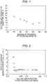
- Fig. 1 illustrates the relationship between the timing of changing top-blowing conditions and bottom-blowing conditions, which are expressed by the degree of progress of oxygen blowing, and dust per unit production after the completion of oxygen blowing.
- Fig. 1 indicated that when the flow rate of top-blown oxygen gas, the lance height, and the flow rate of bottom-blown gas are changed at a small degree of progress of oxygen blowing, the dust per unit production (kg/molten steel-t) at the completion of the oxygen blowing is increased.
- the timing of changing the top-blowing conditions and the bottom-blowing conditions significantly affects the amount of dust generated (iron loss) and that it is important to grasp a state in the converter and determine the timing of changing the top-blowing conditions and the bottom-blowing conditions in order to reduce the amount of dust generated (iron loss).
- throat combustion flame refers to a flame issuing from the throat of the converter toward an upper flue in the converter.
- the emission spectrum of the throat combustion flame contains information about CO gas generated by a decarburization refining in the converter, information about CO 2 gas generated during spontaneous combustion due to the mixing of part of the CO gas and air sucked in the throat portion of the converter, and information about FeO* (intermediate product) originating from iron atoms evaporated from a hot spot in the converter.
- the inventors have conceived that if emission intensity at each wavelength in the range of 580 to 620 nm of the emission spectrum can be measured in real time, the state in the converter can be easily presumed in real time.
- the wavelengths in the range of 580 to 620 nm of the emission spectrum correspond to an "FeO orange system band" attributed to the formation and disappearance of FeO* (intermediate product) and differ from the wavelength range of an intermediate product of a hydrocarbon gas.
- an absorption peak is observed in the wavelength range.
- an emission peak is observed in the same wavelength range. The emission intensity has been confirmed to be associated with the rate of disappearance of FeO*.
- an electromagnetic wave having a specific wavelength the electromagnetic wave being emitted or absorbed at the time of the transition of the electronic state of FeO* mainly formed in the hot spot of molten iron in the converter.
- FeO* is integrated with the flame issuing from the converter.
- the intensity of the electromagnetic wave having a wavelength of 580 to 620 nm is increased.
- the intensity of the electromagnetic wave having a wavelength of 580 to 620 nm is reduced.
- the wavelengths in the range of 580 to 620 nm are associated with reduction light generated at the time of the reduction of FeO by carbon.
- the emission intensity at the wavelengths represents the magnitude of the emission energy when FeO changes from the excited state (FeO*) to the ground state.
- the emission intensity at the wavelengths is increased at the end of the desiliconization period. Thus, a change in spectral intensity seems to correspond to the formation and reduction of FeO with the completion of the desiliconization reaction.
- the emission spectrum of the throat combustion flame in the converter was measured during the oxygen blowing in the converter.
- the emission spectrum of the throat combustion flame in the converter was measured by arranging a spectroscopic camera 6 in front of a converter 2 and photographing a throat combustion flame 12 seen from the gap between a throat 14 and a movable hood 15. An image photographed with the spectroscopic camera 6 was transmitted to an image analyzer 7. The image was recorded in the image analyzer 7. The emission intensity at each emission wavelength was analyzed by line analysis on a freely-selected scan line of the input image data. The measurement of the emission spectrum and the analysis of the emission intensity were performed at a constant measurement time interval ⁇ t of 1 to 10 seconds. Simultaneously with emission spectrum measurement, the collection of molten iron samples and the analysis of silicon concentration in the molten iron were performed once or twice during the oxygen blowing with a sub-lance (automatic temperature measurement sampling device) attached to the converter.
- a wavelength of 610 nm, at which the largest amount of change was observed during the oxygen blowing was defined as a specific wavelength, and the rate of change in emission intensity defined by formula (1) described below was calculated from emission intensity I n at time T n and emission intensity I n-1 at time T n-1 ⁇ t second(s) before time T n at the specific wavelength.
- the measurement time interval ⁇ t was 1 to 10 seconds.
- Rate of change in emission intensity I n / I n ⁇ 1 ⁇ 1
- I n emission intensity (a.u.) at the specific wavelength at time T n
- I n-1 emission intensity (a.u.) at the specific wavelength at time T n-1 ⁇ t second(s) before time T n .
- Fig. 2 illustrates the relationship between the calculated rate of change in emission intensity and silicon concentration in molten iron.
- Fig. 2 indicates that the rate of change in emission intensity changes greatly at a silicon concentration in molten iron of about 0.02% by mass as a boundary. That is, at a silicon concentration in molten iron of less than about 0.02% by mass, the rate of change in emission intensity is increased to more than 1.8.
- the emission intensity at a wavelength of 610 nm is high.
- a silicon concentration in molten iron of about 0.02% or more by mass substantially no emission at a wavelength of 610 nm is observed.
- the effect of shielding the surface of hot metal should be provided by the formation of molten slag. That is, the following was found: in order to prevent a decrease in iron yield due to the increase of dust generation, as an index of the timing of changing the top-blowing conditions and the bottom-blowing conditions such as an increase in the flow rate of top-blown oxygen gas at an early stage of the oxygen blowing, the time when the rate of change in emission intensity exceeds 1.8 after the start of the oxygen blowing is optimal, and this time can be determined as the end of the desiliconization period.
- the "threshold value" of the rate of change in emission intensity represented by formula (1) is 1.8 and that the time when the threshold value is exceeded can be determined as the end of the desiliconization period.
- the "threshold value" of the rate of change in emission intensity is not limited to 1.8 but is determined in advance for each converter.
- emission intensity is determined at time T n , which is used as a reference, time T n-1 ( ⁇ t ⁇ 1) second (s) before time T n , time T n-2 ( ⁇ t ⁇ 2) seconds before time T n , time T n-3 ( ⁇ t ⁇ 3) seconds before time T n , ..., and time T n-S ( ⁇ t ⁇ S) second (s) (where S is an integer of 0 or more) before time T n , and the rate of change in emission intensity is determined using the total (sum) of the resulting values of the emission intensity, i.e., using the moving average of the emission intensity. It was conceived that the use of the moving average of the emission intensity enables variations in emission intensity to be averaged to some extent to reduce variations in the rate of change in emission intensity, thereby resulting in accurate determination.
- Time T n was used as a reference. Values of emission intensity I n-i at time T n-i at the specific wavelength were determined. Specifically, a total of (S + 1) values of emission intensity was determined at time T n , time T n-1 ( ⁇ t ⁇ 1) second(s) before time T n , time T n-2 ( ⁇ t ⁇ 2) seconds before time T n , ..., and time T n-S ( ⁇ t ⁇ S) second (s) before time T n .
- I n-i is emission intensity (a.u.) at the specific wavelength at time T n-i ( ⁇ t ⁇ i) second(s) before time T n .
- Time T n-m ( ⁇ t ⁇ m) second (s) before time T n was used as a reference.
- values of emission intensity I n-m-i at time T n-m-i at the specific wavelength were determined. Specifically, a total of (S + 1) values of emission intensity (where S is an integer of 0 or more) was determined at time T n-m , time T n-m-1 ( ⁇ t ⁇ 1) second (s) before time T n-m , time T n-m-2 ( ⁇ t ⁇ 2) seconds before time T n-m , ..., and time T n-m-S ( ⁇ t ⁇ S) second (s) before time T n-m .
- I n-m-i is emission intensity (a.u.) at the specific wavelength at time T n-m-i ( ⁇ t ⁇ i) second(s) before time T n-m that is a time ( ⁇ t ⁇ m) second(s) before time T n .
- Rate of change in moving average of emission intensity ( I n S ⁇ I n ⁇ m S / I n S + I n ⁇ m S / 2
- I n S is the moving average (a.u.) of emission intensity at the specific wavelength based on time T n where S is the number of terms added
- I n-m S is the moving average (a.u.) of emission intensity at the specific wavelength based on time T n-m ( ⁇ t ⁇ m) second (s) before time T n
- S is the number of terms added
- m is a natural number
- S is the number of terms added in the moving average (an integer of 0 or more)
- ⁇ t is a measurement time interval (s).
- Fig. 3 illustrates the relationship between the calculated rate of change in the moving average of emission intensity and silicon concentration in molten iron.
- the measurement time interval ⁇ t was 1 second.
- the natural number m and the number S of terms added in the moving average were 20.
- Fig. 3 indicates that the rate of change in the moving average of emission intensity, which is calculated by formula (2), changes greatly at the time when the silicon concentration in molten iron is less than about 0.02% by mass as a boundary.
- the rate of change in the moving average of emission intensity is more than 0.4, the effect of shielding the surface of hot metal should be provided by the formation of molten slag.
- the time when the rate of change in the moving average of emission intensity exceeds 0.4 after the start of the oxygen blowing is optimal, and this time can be determined as the end of the desiliconization period.
- the "threshold value" of the rate of change in the moving average of emission intensity is 0.4 and that the time when the threshold value is exceeded can be determined as the end of the desiliconization period.
- the "threshold value" of the rate of change in the moving average of emission intensity is not limited to 0.4 but is determined in advance for each converter.
- the converter includes a tap hole configured to discharge refined molten iron in the converter into a hot metal-holding vessel or a molten steel-holding vessel.
- the tap hole is opened; thus, a flame in the converter is also observed through the tap hole.
- the flame is referred to as a "tap hole combustion flame".
- a state in the converter can be grasped by measuring the emission spectrum of the tap hole combustion flame observed through the tap hole or the tap hole combustion flame observed at the tap hole.
- Fig. 4 schematically illustrates an outline of the configuration of a converter system suited to carry out the present invention.
- a converter system 1 suited to carry out the present invention includes the converter 2, a top blowing lance 3, the spectroscopic camera 6 that is arranged in front of the converter 2 and that can photograph the throat combustion flame 12, the image analyzer 7 configured to retrievably record the image photographed with the spectroscopic camera 6 and analyze the photographed image, and a control computer 8 configured to send a control signal in accordance with data analyzed by the image analyzer 7.
- the converter system 1 further includes a lance-height control device 9 that adjusts the lance height of the top blowing lance 3 and that is configured to be separately operable by a control signal sent from the control computer 8, an oxidizing-gas flow rate control device 10 that adjusts the flow rate of an oxidizing gas jetted from the top blowing lance 3, and a bottom-blown gas flow rate control device 11 that adjusts the flow rate of a stirring gas blown through a bottom blowing tuyere 4.
- a lance-height control device 9 that adjusts the lance height of the top blowing lance 3 and that is configured to be separately operable by a control signal sent from the control computer 8
- an oxidizing-gas flow rate control device 10 that adjusts the flow rate of an oxidizing gas jetted from the top blowing lance 3
- a bottom-blown gas flow rate control device 11 that adjusts the flow rate of a stirring gas blown through a bottom blowing tuyere 4.
- the converter 2 used has a configuration in which an oxidizing gas jet 13 can be blown from the top blowing lance 3 toward a hot metal 5 in the converter and the stirring gas can be simultaneously blown through the bottom blowing tuyere 4 in the bottom section of the converter.
- the spectroscopic camera 6 that can measure the emission spectrum of the throat combustion flame 12 in the converter is arranged in front of the converter 2.
- the throat combustion flame 12 seen from the gap between the throat 14 of the converter and the movable hood 15 is photographed with the spectroscopic camera 6.
- An image (image data) photographed with the spectroscopic camera 6 is sequentially sent to the image analyzer 7. In the image analyzer 7, the sent image (image data) is recorded, and the emission wavelengths and the emission intensity at each wavelength are analyzed by line analysis on a freely-selected scan line.
- the analyzed image data of the throat combustion flame 12 is transmitted to the control computer 8 each time.
- the control computer 8 is configured to send a control signal to individually or simultaneously operate the lance-height control device 9, the oxidizing-gas flow rate control device 10, and the bottom-blown gas flow rate control device 11 in accordance with the input, analyzed image data.
- reference numeral 16 denotes an oxidizing gas supply pipe to the top blowing lance
- reference numeral 17 denotes a cooling water supply pipe to the top blowing lance
- reference numeral 18 denotes a cooling water discharge pipe from the top blowing lance.
- the converter system 1 is used, and the hot metal 5 is subjected to desiliconization, dephosphorization, and decarburization by oxidation refining that is performed by blowing an oxidizing gas from the top blowing lance 3 on the hot metal 5 in the converter 2 or, in addition, blowing an oxidizing gas or an inert gas through the bottom blowing tuyere 4, thereby producing molten steel from the hot metal 5.
- the hot metal 5 contains 0.02% or more by mass silicon.
- a state in the converter during oxygen blowing in the converter 2 is monitored by photographing the throat combustion flame 12 using the spectroscopic camera 6 and analyzing the resulting emission spectrum.
- the photographing of the throat combustion flame 12 using the spectroscopic camera 6 and the analysis of the emission spectrum are preferably performed at measurement time intervals ⁇ t of 1 to 10 seconds from the viewpoint of improving the productivity and the iron yield.
- the emission spectrum obtained by photographing is retrievably recorded in the image analyzer 7.
- analyses for identifying the emission wavelengths and for calculating emission intensity at each wavelength are performed in a wavelength range of 580 to 620 nm of the resulting emission spectrum of the throat combustion flame 12.
- the wavelengths in the range of 580 to 620 nm corresponds to a "FeO orange system band" attributed to the formation and disappearance of FeO* (intermediate product) as described above.
- an absorption peak is observed in the wavelength range.
- an emission peak is observed in the same wavelength range.
- the emission intensity has been confirmed to be associated with the rate of disappearance of FeO*.
- the wavelengths in the range of 580 to 620 nm were targeted for measurement because the wavelengths reflect the reactions in the converter and provide a clue to an easy presumption of a state in the converter.
- the emission intensity represents the magnitude of the emission energy when FeO changes from the excited state (FeO*) to the ground state.
- a temporal change in emission intensity at each wavelength is calculated, the change of the state in the converter is presumed from the temporal change in emission intensity and used for monitoring the operation of the converter.
- the rate of change in emission intensity at a specific wavelength represented by formula (1) or the rate of change in the moving average of the emission intensity at the specific wavelength represented by formula (2) is calculated and used as a temporal change in the emission intensity of the emission spectrum obtained by photographing the throat combustion flame 12.
- the specific wavelength used for the calculation of the rate of change in emission intensity and the rate of change in the moving average of the emission intensity is determined by measuring, in advance, a wavelength at which the largest amount of change in emission intensity is observed during oxygen blowing in the wavelength range of 580 to 620 nm or by monitoring multiple wavelengths in the wavelength range during the oxygen blowing and determining a wavelength at which the largest amount of change in emission intensity is observed in each time.
- a temporal change in emission intensity is calculated at the specific wavelength in the range of 580 to 620 nm of the measured emission spectrum.
- the rate of change in emission intensity defined by formula (1) and the rate of change in the moving average of emission intensity defined by formula (2) vary greatly at a silicon concentration in molten iron of about 0.02% by mass as a boundary. At a silicon concentration in the molten iron of less than about 0.02% by mass, the rate of change in emission intensity and the rate of change in the moving average of emission intensity are increased. At a silicon concentration in the molten iron of 0.02% or more by mass, substantially no light emission is observed in the wavelength range.
- one or two or more of changes i.e., the increase in the flow rate of the top-blown oxidizing gas, the reduction in lance height, and the reduction in the flow rate of the bottom-blown gas, in the early stage of the oxygen blowing are performed at the time when the rate of change in emission intensity defined by formula (1) exceeds a preset threshold value or at the time when the rate of change in the moving average of emission intensity defined by formula (2) exceeds a preset threshold value. In other words, these are performed at the time when the oxidation of silicon in the molten iron is almost completed.
- preset threshold value refers to each of the rate of change in emission intensity and the rate of change in the moving average of emission intensity at the time when silicon concentration in molten iron is less than about 0.02%, both rates being determined in advance by performing a preliminary test for each converter.
- the lance height of the top blowing lance is reduced or the flow rate of the oxidizing gas or the inert gas blown through the bottom blowing tuyere is reduced, simultaneously with an increase in the flow rate of the oxidizing gas blown from the top blowing lance.
- the adjustments enable the generation of dust to be suppressed to improve the iron yield.
- the amount of increase in the flow rate of the oxidizing gas blown from the top blowing lance, the amount of reduction in the lance height of the top blowing lance, and the amount of reduction in the flow rate of the oxidizing gas or the inert gas blown through the bottom blowing tuyere are preferably determined in advance on the basis of, for example, the ratio of a force to stir molten iron to the flow rate of the oxidizing gas.
- the converter system 1 suited to carry out the first embodiment of the present invention is preferably configured to transmit a control signal from the control computer 8 to the lance-height control device 9 so as to reduce the lance height, to transmit a control signal to the oxidizing-gas flow rate control device 10 so as to increase the flow rate of the oxidizing gas jetted, to transmit a control signal to the bottom-blown gas flow rate control device 11 so as to reduce the flow rate of the oxidizing gas or inert gas blown, or to simultaneously transmit all of these control signals at each time when the rate of change in emission intensity defined by formula (1) exceeds a preset threshold value or at each time when the rate of change in the moving average of emission intensity defined by formula (2) exceeds a preset threshold value.
- the oxidizing gas blown from the top blowing lance 3 is typically oxygen gas.
- a mixed gas of oxygen gas and a rare gas, such as argon gas or helium gas, or nitrogen gas, air, or oxygen-enriched air may be used.
- the term "oxidizing gas" used here refers to an oxygen-containing gas having an oxygen concentration equal to or higher than air.
- the gas blown through the bottom blowing tuyere 4 is an inert gas or an oxidizing gas. In the case of blowing an oxidizing gas, the oxidizing gas functions as an oxidizing gas for oxidation refining and also functions as a stirring gas.
- the above description is an example in which the state in the converter 2 during the oxygen blowing is monitored in real time by photographing the throat combustion flame 12.
- the state in the converter 2 during the oxygen blowing can also be monitored in real time by measuring the emission spectrum of the tap hole combustion flame observed from the tap hole of the converter 2.
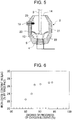
- Fig. 5 illustrates a schematic view of the converter when the converter 2 illustrated in Fig. 4 is viewed in a different direction from that in Fig. 4 (direction perpendicular to that in Fig. 4 ).
- the converter 2 in which the outer shell is a steel shell 21 and a refractory material 22 is arranged inside the steel shell 21 includes a tap hole 19 penetrating the refractory material 22 arranged on one side wall.
- the internal pressure of the converter 2 is controlled to a pressure slightly lower than atmospheric pressure during the oxygen blowing. Air enters the converter through the tap hole 19. A tap hole combustion flame 20 does not issue from the tap hole 19. Thus, in this case, as with the case of measuring the throat combustion flame 12, the state in the converter 2 during the oxygen blowing can be monitored in real time by measuring the emission spectrum of the tap hole combustion flame 20 with the spectroscopic camera through the tap hole 19.
- the tap hole combustion flame 20 issues from the tap hole 19 to the outside the converter, thus facilitating the measurement of the tap hole combustion flame 20.
- Reference numeral 23 in Fig. 5 denotes slag.
- any of common oxygen blowing methods can be employed in the latter half of the oxygen blowing, and the method is not particularly limited.
- one or two or more of a reduction in the flow rate of the oxidizing gas blown from the top blowing lance, a reduction in the lance height of the top blowing lance, and an increase in the flow rate of the oxidizing gas or the inert gas blown through the bottom blowing tuyere are preferably performed at the time when the degree of progress of oxygen blowing is appropriate (for example, at the time when carbon concentration in molten iron is estimated at 0.35% by mass on the basis of thermal material calculations by an existing process computer).
- the emission spectrum of the throat combustion flame issuing from the throat of the converter or the tap hole combustion flame is measured.
- the rate of change in emission intensity defined by formula (1) or the rate of change in the moving average of emission intensity defined by formula (2) is calculated as a temporal change in emission intensity at a specific wavelength in the range of 580 to 620 nm of the emission spectrum.
- the top-blowing conditions and the bottom-blowing conditions may be changed at the time when the rate of change in emission intensity or the rate of change in the moving average of emission intensity satisfies a preset threshold value or less. This avoids an increase in iron oxide concentration in slag to improve the iron yield.
- the hot metal subjected to decarburization refining may have any silicon content and any phosphorus content.
- the decarburization reaction rate is limited by oxygen supply for a period until carbon concentration in molten iron reaches a critical carbon concentration and that the decarburization reaction rate is limited by mass transfer (diffusion) of carbon in molten iron for a period in which the carbon concentration in the molten iron is lower than the critical carbon concentration.
- the state in which the decarburization reaction rate is limited by oxygen supply refers to a state in which the decarburization reaction rate is determined by an oxygen supply rate regardless of the carbon concentration in the molten iron. Accordingly, for the period in which the rate is limited by oxygen supply, increasing the feed rate of the oxidizing gas increases the decarburization reaction rate.
- a converter (capacity: 300 tons) was used and configured to enable a stirring gas to be blown through a bottom blowing tuyere in the bottom section of the converter while an oxidizing gas can be blown from a top blowing lance.
- Oxygen gas (industrial pure oxygen gas) was used as the oxidizing gas blown from the top blowing lance.
- Argon gas was used as the stirring gas blown through the bottom blowing tuyere.
- a top blowing lance having five Laval jet nozzles serving as oxygen gas jet nozzles arranged on its tip portion and at a jet angle of 15° was used.
- Hot metal having a carbon concentration of 3.5% by mass was subjected to decarburization refining using the converter.
- the supply of oxygen gas from the top blowing lance was started at the time when the hot metal had a carbon content of 3.5% by mass and continued to the time when the molten iron in the converter had a carbon content of 0.04% by mass.
- the flow rate of oxygen gas blown from the top blowing lance, the lance height of the top blowing lance, and the flow rate of the stirring gas blown through the bottom blowing tuyere were manually changed at the same time.
- the timing of changing the top-blowing conditions and the bottom-blowing conditions was changed variously around the time when the rate-determining step of the decarburization reaction in the latter half of the decarburization refining is changed from oxygen supply to the mass transfer of carbon in molten iron.
- the flow rate of oxygen gas from the top blowing lance was changed so as to be reduced from 1,000 Nm 3 /min to 833 Nm 3 /min.
- the lance height of the top blowing lance was changed so as to be reduced from 2.5 m to 2.0 m.
- the flow rate of the stirring gas through the bottom blowing tuyere was changed so as to be 15 Nm 3 /min to 30 Nm 3 /min.
- slag generated by each decarburization refining operation was collected.
- the iron oxide content (% by mass, FeO) of the slag was measured by X-ray fluorescence analysis.
- the timing of changing the flow rate of top-blown oxygen gas, the lance height, and the flow rate of the bottom-blown gas was organized in terms of the degree of progress of oxygen blowing defined by formula (3) below.
- Fig. 6 illustrates the relationship between the timing of change expressed by the degree (%) of progress of oxygen blowing and the iron oxide content of slag (% by mass, FeO) after the completion of decarburization refining.
- Fig. 6 indicates that the iron oxide content (% by mass, FeO) of slag at the time of the completion of the decarburization refining increases as the degree of progress of oxygen blowing increases at the time when the top-blowing conditions and the bottom-blowing conditions are changed.
- the slag has a high iron oxide content (% by mass, FeO) after the completion of the decarburization refining.
- the inventors have found that the timing of changing the top-blowing conditions and the bottom-blowing conditions significantly affects iron loss and that it is important to grasp a state in the converter and determine the timing of changing the top-blowing conditions and the bottom-blowing conditions in order to reduce the iron oxide content (% by mass, FeO) of slag at the time of the completion of the decarburization refining.
- the inventors have focused their attention on a throat combustion flame in the converter and have conceived the idea of measuring the emission spectrum of the throat combustion flame during the decarburization refining.
- the emission spectrum of the throat combustion flame contains information about CO gas generated by the decarburization refining in the converter, information about CO 2 gas generated during spontaneous combustion due to the mixing of part of the CO gas and air sucked in the throat portion of the converter, and information about FeO* (intermediate product) originating from iron atoms evaporated from a hot spot in the converter. If emission intensity at each wavelength in the range of 580 to 620 nm of the emission spectrum can be measured in real time, the state in the converter can be easily presumed in real time.
- the wavelengths in the range of 580 to 620 nm of the emission spectrum correspond to an "FeO orange system band" attributed to the formation and disappearance of FeO* (intermediate product).
- the inventors have confirmed the following: At the time of the formation of FeO*, an absorption peak is observed in the wavelength range. At the time of the disappearance of FeO*, an emission peak is observed in the same wavelength range. The emission intensity is associated with the rate of disappearance of FeO*.
- an electromagnetic wave having a specific wavelength the electromagnetic wave being emitted or absorbed at the time of the transition of the electronic state of FeO* mainly formed in the hot spot of molten iron in the converter.
- FeO* is integrated with the flame issuing from the converter.
- the intensity of the electromagnetic wave having a wavelength of 580 to 620 nm is reduced.
- the emission spectrum of the throat combustion flame in the converter was measured during the decarburization refining in the converter.
- the emission spectrum of the throat combustion flame in the converter was measured by arranging the spectroscopic camera 6 in front of the converter 2 and photographing the throat combustion flame 12 seen from the gap between the throat 14 and the movable hood 15.
- the image photographed with the spectroscopic camera 6 was transmitted to the image analyzer 7.
- the image was recorded in the image analyzer 7.
- the emission intensity at each emission wavelength was analyzed by line analysis on a freely-selected scan line of the input image data.
- the measurement of the emission spectrum and the analysis of the emission intensity were performed at a constant measurement time interval ⁇ t of 1 to 10 seconds.
- the collection of molten iron samples and the analysis of carbon concentration in the molten iron were performed once or twice during the decarburization refining with a sub-lance (automatic temperature measurement sampling device) attached to the converter.
- a wavelength of 610 nm, at which the largest amount of change was observed during the decarburization refining was defined as a specific wavelength, and the rate of change in emission intensity defined by formula (1) described below was calculated from emission intensity I n at time T n and emission intensity I n-1 at time T n-1 ⁇ t second (s) before time T n at the specific wavelength.
- the measurement time interval ⁇ t was 1 to 10 seconds.
- Rate of change in emission intensity I n / I n ⁇ 1 ⁇ 1
- I n emission intensity (a.u.) at the specific wavelength at time T n
- I n-1 emission intensity (a.u.) at the specific wavelength at time T n-1 ⁇ t second(s) before time T n .
- Fig. 7 illustrates the relationship between the calculated rate of change in emission intensity and carbon concentration in molten iron.
- Fig. 7 indicates that the rate of change in emission intensity changes greatly at a carbon concentration in molten iron of about 0.45% by mass as a boundary. That is, at a carbon concentration in molten iron of about 0.45% or more by mass, the rate of change in emission intensity is increased to more than 1.8.
- the emission intensity at a wavelength of 610 nm is high.
- substantially no emission at a wavelength of 610 nm is observed.
- Fig. 7 indicated that the time when the carbon concentration in molten iron is less than about 0.45% by mass, in other words, the time when the rate of change in emission intensity satisfies 1.8 or less, is optimal as an index of the timing of changing the top-blowing conditions and the bottom-blowing conditions at the end stage of the decarburization refining.
- the "threshold value" of the rate of change in emission intensity is 1.8, and as an index of the timing of changing the top-blowing conditions and the bottom-blowing conditions such as a reduction in the flow rate of the top-blown oxygen gas, the time when the rate of change in emission intensity, which is calculated by formula (1), satisfies 1.8 or less in the latter half of the decarburization refining is optimal.
- the "threshold value" of the rate of change in emission intensity is not limited to 1.8 but is determined in advance for each converter.
- Rate of change in moving average of emission intensity ( I n S ⁇ I n ⁇ m S / I n S + I n ⁇ m S / 2
- I n S is the moving average (a.u.) of emission intensity at the specific wavelength based on time T n where S is the number of terms added
- I n-m S is the moving average (a.u.) of emission intensity at the specific wavelength based on time T n-m ( ⁇ t ⁇ m) second (s) before time T n
- S is the number of terms added
- m is a natural number
- S is a number of terms added in the moving average (an integer of 0 or more)
- ⁇ t is a measurement time interval (s).
- Fig. 8 illustrates the relationship between the calculated rate of change in the moving average of emission intensity and carbon concentration in molten iron.
- the measurement time interval ⁇ t was 1 second.
- the natural number m and the number S of terms added in the moving average were 10.
- Fig. 8 indicates that the rate of change in the moving average of emission intensity changes greatly at the time when the carbon concentration in molten iron is about 0.45% by mass as a boundary.
- the rate of change in the moving average of emission intensity increases as the decarburization refining proceeds.
- the carbon concentration in molten iron is less than about 0.45% by mass, the emission decreases.
- Fig. 8 indicated that the time when the carbon concentration in molten iron is less than about 0.45% by mass, in other words, the time when the rate of change in moving average of emission intensity satisfies a preset threshold value (dotted line: 1.6 here) or less, is optimal as an index of the timing of changing the top-blowing conditions and the bottom-blowing conditions at the latter half of the decarburization refining in order to prevent a decrease in iron yield due to an increase in the iron oxide content (% by mass, FeO) of slag.
- the "threshold value" of the rate of change in the moving average of emission intensity is not limited to 1.6 but is determined in advance for each converter.
- the state in the converter during the decarburization refining in the converter is grasped by measuring the emission spectrum of the throat combustion flame.
- the state in the converter during the decarburization refining in the converter can also be grasped by measuring the emission spectrum of a tap hole combustion flame observed through a tap hole or the tap hole combustion flame observed at the tap hole as in the case of measuring the emission spectrum of the throat combustion flame.
- a converter system used in the second embodiment of the present invention has the same structure as the converter system 1, illustrated in Fig. 4 , used in the first embodiment of the present invention. Thus, detailed description of the converter system is omitted.
- the converter system 1 is used, and the hot metal 5 is subjected to oxidation refining, in other words, the hot metal 5 is subjected to decarburization refining, to produce molten steel from the hot metal 5 by blowing an oxidizing gas on the hot metal 5 in the converter 2 from the top blowing lance 3 or, in addition, blowing an oxidizing gas or an inert gas through the bottom blowing tuyere 4.
- the hot metal 5 used contains 0.02% or more by mass silicon, a desiliconization reaction occurs first and then a decarburization reaction and a dephosphorization reaction occur.
- the decarburization reaction and the dephosphorization reaction occur from an early stage of the decarburization refining.
- the operation of a converter according to the second embodiment of the present invention is targeted at the latter half of the decarburization refining. Regardless of reaction patterns at the early stage of the decarburization refining, the same reaction patterns occur in the latter half of the decarburization refining. Thus, the reaction patterns in the early stage of the decarburization refining are not a problem.
- a state in the converter during decarburization refining in the converter 2 is monitored by photographing the throat combustion flame 12 using the spectroscopic camera 6 and analyzing the resulting emission spectrum.
- the photographing of the throat combustion flame 12 using the spectroscopic camera 6 and the analysis of the emission spectrum are preferably performed at measurement time intervals ⁇ t of 1 to 10 seconds from the viewpoint of improving the productivity and the iron yield.
- the emission spectrum obtained by photographing is retrievably recorded in the image analyzer 7.
- analyses for identifying the emission wavelengths and for calculating emission intensity at each wavelength are performed in a wavelength range of 580 to 620 nm of the resulting emission spectrum of the throat combustion flame 12.
- a temporal change in emission intensity at each wavelength is calculated, the change of the state in the converter is presumed from the temporal change in emission intensity and used for monitoring the operation of the converter.
- the rate of change in emission intensity at a specific wavelength represented by formula (1) or the rate of change in the moving average of the emission intensity at the specific wavelength represented by formula (2) is calculated and used as a temporal change in the emission intensity of the emission spectrum obtained by photographing the throat combustion flame 12.
- the specific wavelength used for the calculation of the rate of change in emission intensity and the rate of change in the moving average of the emission intensity is determined by measuring, in advance, a wavelength at which the largest amount of change in emission intensity is observed during decarburization refining in the wavelength range of 580 to 620 nm or by monitoring multiple wavelengths in the wavelength range during the decarburization refining and determining a wavelength at which the largest amount of change in emission intensity is observed in each time.
- a temporal change in emission intensity is calculated at the specific wavelength in the range of 580 to 620 nm of the measured emission spectrum.
- one or two or more of a reduction in the flow rate of the oxidizing gas blown from the top blowing lance, a reduction in lance height, and an increase in the flow rate of an oxidizing gas or an inert gas blown through the bottom blowing tuyere are performed at the time when the rate of change in emission intensity defined by formula (1) satisfies a preset threshold value (for example, 1.8) or less or at the time when the rate of change in the moving average of emission intensity defined by formula (2) satisfies a preset threshold value (for example, 1.6) or less.
- a preset threshold value for example, 1.8
- the phrase “latter half of latter half of decarburization refining” used here refers to a period after 1/2 of the total oxygen supply scheduled for the charge is supplied.
- the phrase “preset threshold value” used in the second embodiment refers to each of the rate of change in emission intensity and the rate of change in the moving average of emission intensity at the time when carbon concentration in molten iron is less than about 0.45%, both rates being determined in advance by performing a preliminary test for each converter.
- the lance height of the top blowing lance is reduced or the flow rate of the oxidizing gas or the inert gas blown through the bottom blowing tuyere is increased, simultaneously with a reduction in the flow rate of the oxidizing gas blown from the top blowing lance.
- the adjustments enable an improvement in oxygen efficiency for decarburization, the suppression of the peroxidative state of molten iron in the converter, the inhibition of an excessive increase in iron oxide concentration in slag, and an improvement in iron yield.
- the carbon concentration in molten iron is believed to be a critical carbon concentration or less.
- the critical carbon concentration varies depending on a force to stir molten iron of the top-blown gas and the bottom-blown gas and the flow rate of the oxidizing gas, and is about 0.45% or less by mass.
- the decarburization reaction rate is limited by the mass transfer of carbon in molten iron, a portion of the blown oxidizing gas is in a state where it is easily accumulated as iron oxide in slag.
- excess supply of the oxidizing gas leads to a decrease in oxygen efficiency for decarburization and a decrease in iron yield.
- the rate-determining step of the decarburization reaction is changed to the mass transfer of carbon in molten iron, in other words, at the time when each of the rate of change in emission intensity and the rate of change in the moving average of emission intensity satisfies the preset threshold value or less, one or more of a reduction in the flow rate of the oxidizing gas blown from the top blowing lance, the reduction in lance height, and an increase in the flow rate of the oxidizing gas or the inert gas blown through the bottom blowing tuyere are adjusted, thereby suppressing the peroxidative state of molten iron in the converter to reduce an excessive increase in iron oxide concentration in slag.
- the amount of reduction in the flow rate of the oxidizing gas blown from the top blowing lance, the amount of reduction in the lance height of the top blowing lance, and the amount of increase in the flow rate of the oxidizing gas or the inert gas blown through the bottom blowing tuyere are preferably determined in advance on the basis of, for example, the ratio of a force to stir molten iron to the flow rate of the oxidizing gas.
- the converter system 1 suited to carry out the second embodiment of the present invention is preferably configured to transmit a control signal from the control computer 8 to the lance-height control device 9 so as to reduce the lance height, to transmit a control signal to the oxidizing-gas flow rate control device 10 so as to reduce the flow rate of the oxidizing gas jetted, to transmit a control signal to the bottom-blown gas flow rate control device 11 so as to increase the flow rate of the oxidizing gas or inert gas blown, or to simultaneously transmit all of these control signals at each time when the rate of change in emission intensity defined by formula (1) satisfies a preset threshold value or less or at each time when the rate of change in the moving average of emission intensity defined by formula (2) satisfies a preset threshold value or less.
- the oxidizing gas blown from the top blowing lance 3 is typically oxygen gas.
- a mixed gas of oxygen gas and a rare gas, such as argon gas or helium gas, or nitrogen gas, air, or oxygen-enriched air may be used.
- the term "oxidizing gas" used here refers to an oxygen-containing gas having an oxygen concentration equal to or higher than air.
- the gas blown through the bottom blowing tuyere 4 is an inert gas or an oxidizing gas. In the case of blowing an oxidizing gas, the oxidizing gas functions as an oxidizing gas for oxidation refining and also functions as a stirring gas.
- the above description is an example in which the state in the converter 2 during the decarburization refining is monitored in real time by photographing the throat combustion flame 12.
- the state in the converter 2 during the decarburization refining can also be monitored in real time by measuring the emission spectrum of the tap hole combustion flame 20 observed from the tap hole of the converter 2 in the same manner as the throat combustion flame 12.
- the measurement of the emission spectrum of the tap hole combustion flame 20 has been described in the first embodiment, and thus the description is omitted.
- the pretreatment of hot metal has been widely performed in each of the converters used in the first and second embodiments. That is, as the pretreatment of hot metal, desiliconization treatment and dephosphorization treatment of hot metal are performed in the converter. Subsequent to the pretreatment, the decarburization refining of hot metal left in the converter is performed in the same converter.
- This method may not include the deslagging step between the desiliconization treatment step and the dephosphorization treatment step.
- a tapping step of discharging hot metal that has been subjected to dephosphorization treatment from the converter is provided after the dephosphorization treatment step.
- the hot metal discharged in the tapping step is charged into the decarburization converter.
- the decarburization converter is not contaminated with slag formed in the dephosphorization treatment step, thereby reducing the amount of the CaO-based flux used in the decarburization converter.
- CaO-based flux examples include quicklime, limestone, hydrated lime, and dolomite.
- decarburized slag slag formed by decarburization refining
- CaO-based flux examples include quicklime, limestone, hydrated lime, and dolomite.
- a method is employed in which one converter is used, desiliconization treatment, dephosphorization treatment, and decarburization refining are performed in this order, and a deslagging step of discharging at least part of slag in the converter is included between the dephosphorization treatment step and the decarburization refining step. Because at least part of slag formed in the desiliconization treatment step and the dephosphorization treatment step is discharged, the amount of the CaO-based flux used in the decarburization refining step is reduced.
- This method may further include a slagging step between the desiliconization treatment step and the dephosphorization treatment step or may not include a deslagging step between the dephosphorization treatment step and the decarburization refining step.
- the desiliconization treatment step described in [1] and [2] above targets hot metal having a silicon content of 0.02% or more by mass.
- the end of the desiliconization treatment step in the pretreatment can be determined according to a method for determining the end of a desiliconization period described in the first embodiment.
- the emission spectrum of the throat combustion flame 12 issuing from the throat of the converter 2 or the emission spectrum of the tap hole combustion flame 20 observed through the tap hole 19 of the converter 2 is measured.
- the rate of change in emission intensity defined by formula (1) or the rate of change in the moving average of emission intensity defined by formula (2) is calculated as a temporal change in emission intensity in a wavelength range of 580 to 620 nm of the emission spectrum measured.
- the deslagging step of discharging the slag formed in the desiliconization treatment step or the desiliconization treatment step and the dephosphorization treatment step is performed at the time when the calculated rate of change in emission intensity or rate of change in the moving average of emission intensity exceeds a preset threshold value, at the time when a predetermined period of time elapses based on the time when the calculated rate exceeds a preset threshold value, or at the time when a predetermined amount of oxygen is supplied.
- the end of the desiliconization treatment step or the ends of the desiliconization treatment step and the dephosphorization treatment step can be reliably grasped.
- the reliable grasping of the end of the desiliconization treatment step or the ends of the desiliconization treatment step and the dephosphorization treatment step result in the prevention of the peroxidation of molten iron described above, sufficient oxidative removal in slag, a reduction in the amount of CaO-based flux used in the subsequent dephosphorization treatment step or decarburization refining step, and the prevention of excessive decarburization in molten iron. Accordingly, the amount of carbon carried over the subsequent dephosphorization treatment step or decarburization refining step is increased to save a heat-up material such as a recarburizer, thereby enabling an economically advantageous operation.
- the method described in the second embodiment can be employed in the latter half of the decarburization refining, the method including controlling the top-blowing conditions and the bottom-blowing conditions in accordance with carbon concentration in molten iron to reduce iron oxide in slag.
- the emission spectrum of the throat combustion flame 12 issuing from the throat of the converter 2 or the emission spectrum of the tap hole combustion flame 20 observed through the tap hole 19 of the converter 2 is measured.
- the rate of change in emission intensity defined by formula (1) or the rate of change in the moving average of emission intensity defined by formula (2) is calculated as a temporal change in emission intensity in a wavelength range of 580 to 620 nm of the emission spectrum measured.
- One or two or more of a reduction in the flow rate of the oxidizing gas blown from the top blowing lance, a reduction in the lance height of the top blowing lance, and an increase in the flow rate of the oxidizing gas or the inert gas blown through the bottom blowing tuyere are adjusted at the time when the calculated rate of change in emission intensity or rate of change in the moving average of emission intensity satisfies a preset threshold value or less in the latter half of the decarburization refining step.
- formulae (1) and (2) are used as the temporal change in emission intensity.
- the temporal change in emission intensity is not limited to formulae (1) or (2).
- Another formula can be used.
- formula (6) using a moving average can be used.
- I n emission intensity (a.u.) at a specific wavelength at time T n
- I n-i emission intensity (a.u.) at the specific wavelength at time T n-i ( ⁇ t ⁇ i) second(s) before time T n
- I n-1-i emission intensity (a.u.) at the specific wavelength at time T n-1-i ( ⁇ t ⁇ i) second (s) before time T n-1 ( ⁇ t ⁇ 1) second(s) before time T n
- S is the number of terms added in the moving average (an integer of 0 or more)
- ⁇ t is a measurement time interval (s).
- Formula (6) is determined as described below.
- Time T n is used as a reference. Values of emission intensity I n-i at time T n-i at the specific wavelength are determined. Specifically, a total of (S + 1) values of emission intensity is determined at time T n , time T n-1 ( ⁇ t ⁇ 1) second(s) before time T n , time T n-2 ( ⁇ t ⁇ 2) seconds before time T n , ..., and time T n-S ( ⁇ t ⁇ S) second (s) before time T n . The values are added up (summed), and the moving average of the emission intensity based on time T n is calculated using formula (7) below. Note that I n-i is emission intensity (a.u.) at the specific wavelength at time T n-i ( ⁇ t ⁇ i) second(s) before time T n . Formula (7) is identical to formula (4) described above.
- Time T n-1 ( ⁇ t ⁇ 1) second (s) before T n is used as a reference.
- values of emission intensity I n-1-i at time T n-1-i at the specific wavelength are determined.
- a total of (S + 1) values of emission intensity (where S is an integer of 0 or more) is determined at time T n-1 , time T n-1-1 ( ⁇ t ⁇ 1) second (s) before time T n-1 , time T n-1-2 ( ⁇ t ⁇ 2) seconds before time T n-1 , ..., and time T n-1-S ( ⁇ t ⁇ S) second (s) before time T n-1 .
- I n-1-i is emission intensity (a.u.) at the specific wavelength at time T n-1-i ( ⁇ t ⁇ i) second (s) before time T n-1 ( ⁇ t ⁇ 1) second(s) before time T n .
- Formula (6) described above is determined from the moving average of emission intensity calculated using formula (7) based on time T n and the moving average of emission intensity calculated using formula (8) based on time T n-1 .
- the rate of change in the moving average of emission intensity defined by formula (6) is referred to as a "rate of change in the moving average of emission intensity A".
- the rate of change in the moving average of emission intensity defined by formula (2) targets the same measurement data as that of the rate of change in the moving average of emission intensity A defined by formula (6).
- formula (2) can target the largest number of measurement data sets.
- the desiliconization, dephosphorization, and decarburization of the hot metal 5 were performed by oxidation refining of the hot metal 5 with a 300-ton-capacity top-bottom blown converter (top-blown oxygen gas, bottom-blown argon gas) having the same structure as the converter 2 illustrated in Fig. 4 .
- the top blowing lance 3 used included five Laval-nozzle-type jet nozzles arranged on its tip portion, the jet nozzles being arranged concentrically to the axial center of the top blowing lance at regular intervals and at a jet angle of 15°.
- the jet nozzles had a throat diameter d t of 73.6 mm and an exit diameter d e of 78.0 mm.
- the oxidation refining of the hot metal was started by blowing oxygen gas serving as an oxidizing gas from the top blowing lance on the surface of the hot metal while argon gas serving as a stirring gas was blown into the hot metal through the bottom blowing tuyere 4.
- the amount of scrap iron charged was adjusted in such a manner that the temperature of molten steel after the completion of the oxidation refining was 1,650°C.
- Oxidation refining was performed by charging quicklime serving as a CaO-based flux from a hopper (not illustrated) located above the converter during oxygen blowing until carbon concentration in molten iron was 0.05% by mass.
- the amount of quicklime charged was adjusted in such a manner that the basicity ((CaO, % by mass)/(SiO 2 , % by mass)) of slag formed in the converter was 2.5.
- the throat combustion flame 12 seen from the gap between the throat of the converter 2 and a movable hood was continuously photographed with the spectroscopic camera 6 located almost in front of the converter 2 at predetermined measurement time intervals ⁇ t of 1 to 10 seconds during the oxygen blowing. From the photographed image, an emission spectrum (image data) was measured by the image analyzer 7. Analyses for identifying emission wavelengths and for calculating emission intensity I n at each wavelength were performed at each point of time in a wavelength range of 580 to 620 nm of the resulting emission spectrum. A wavelength (specific wavelength) used was 610 nm. The analyses were performed by line analysis on a freely-selected scan line of the image data.
- the rate of change in emission intensity defined by formula (1) was calculated using the resulting emission intensity at the specific wavelength at each point of time and used as an index of a state in the converter at each point of time, and the operation of the converter was monitored. As presented in Table 2, one or two or more of the flow rate of the oxidizing gas from the top blowing lance, the lance height of the top blowing lance, and the flow rate of the bottom-blown gas were adjusted at each time when the resulting rate of change in emission intensity satisfied more than 1.8 after the start of the blowing of oxygen gas from the top blowing lance.
- the flow rate of the oxidizing gas from the top blowing lance was adjusted so as to be increased from 833 Nm 3 /min to 1,000 Nm 3 /min.
- the lance height was adjusted so as to be reduced from 3.0 m to 2.55 m.
- the flow rate of the bottom-blown gas was adjusted so as to be reduced from 30 Nm 3 /min to 15 Nm 3 /min.
- the adjustments were performed by immediately transmitting control signals from the control computer 8 to the lance-height control device 9, the oxidizing-gas flow rate control device 10, and the bottom-blown gas flow rate control device 11 for operation at each time when the rate of change in emission intensity satisfied more than 1.8.
- a control signal was not transmitted from the control computer 8 to a control device that was not required and was transmitted only to a control device that was required.
- the flow rate of the oxidizing gas from the top blowing lance was reduced from 1,000 Nm 3 /min to 833 Nm 3 /min
- the lance height of the top blowing lance was reduced from 2.5 m to 2.0 m
- the flow rate of the bottom-blown gas was increased from 15 Nm 3 /min to 30 Nm 3 /min at the time when carbon concentration in molten iron was estimated at 0.35% by mass on the basis of thermal material calculations by the existing process computer.
- the dust per unit production was lower than the comparative example, and the iron yield was improved.
- the examples and the comparative example were almost identical in terms of the refining time.
- One or two or more of the flow rate of the oxidizing gas from the top blowing lance, the lance height of the top blowing lance, and the flow rate of the bottom-blown gas were adjusted at each time when the resulting rate of change in the moving average of emission intensity exceeded a threshold value of 0.4 after the start of the blowing of oxygen gas from the top blowing lance as presented in Table 3.
- the flow rate of the oxidizing gas from the top blowing lance was adjusted so as to be increased from 833 Nm 3 /min to 1,000 Nm 3 /min.
- the lance height was adjusted so as to be reduced from 3.0 m to 2.5 m.
- the flow rate of the bottom-blown gas was adjusted so as to be reduced from 30 Nm 3 /min to 15 Nm 3 /min.
- the dust per unit production was lower than the comparative examples, and the iron yield was improved.
- the examples and the comparative examples were almost identical in terms of the refining time.
- Hot metal was subjected to oxidation refining as in Examples 1 and 2 using the same converter system (top-bottom blowing converter) as in Examples 1 and 2.
- the throat combustion flame 12 seen from the gap between the throat of the converter 2 and a movable hood was continuously photographed with the spectroscopic camera 6 at measurement time intervals ⁇ t of 1 second throughout oxygen blowing serving as oxidation refining, as in Examples 1 and 2. From the photographed image, an emission spectrum (image data) was measured and recorded by the image analyzer 7.
- the resulting image data was analyzed offline. Regarding analysis, analyses for identifying the emission wavelengths and for calculating emission intensity I n at each wavelength were performed at each point of time in a wavelength range of 580 to 620 nm of the resulting emission spectrum (image data). The analyses were performed by line analysis on a freely-selected scan line of the image data.
- the specific wavelength was determined to be 610 nm.
- the rate of change in the moving average of emission intensity defined by formula (2) was calculated using the resulting emission intensity at the specific wavelength at each point of time at a total of six levels: the number S of terms added in the moving average was set at three levels of 0 (instantaneous value), 10, and 30, and the natural number m was set at four levels of 1, 10, 30, and 60.
- the time when the resulting rate of change in the moving average of emission intensity exceeded "a preset threshold value of 0.4" was determined as a "point of changing the top-blowing conditions and the bottom-blowing conditions" for each oxygen blowing operation.
- the "point of changing the top-blowing conditions and the bottom-blowing conditions (point of change according to the present invention)" determined from the rate of change in the moving average of emission intensity defined by formula (2) was compared with the "point of changing the top-blowing conditions and the bottom-blowing conditions (timing of appropriate detection)" determined by the manual analysis.
- the case where the "point of changing the top-blowing conditions and the bottom-blowing conditions (timing of appropriate detection)" determined by the manual analysis is matched with the change point according to the present invention was referred to as "appropriate detection”.
- the case where the change point according to the present invention is earlier than the "point of changing the top-blowing conditions and the bottom-blowing conditions (timing of appropriate detection)" determined by the manual analysis is referred to as "overdetection".
- the case where the change point according to the present invention is later than the point determined by the manual analysis is referred to as “nondetection”.
- the “nondetection” includes the case where the rate of change in the moving average of emission intensity defined by formula (2) does not exceed the "preset threshold value" to fail to determine the "point of changing the top-blowing conditions and the bottom-blowing conditions".
- Table 4 presents the results of comparisons for each number S of terms added in the moving average as percentages (%) based on the total amount changed.
- Number S of terms added in moving average Natural number m Percentage based on total amount changed (%) Appropriate detection Overdetection Nondetection Level 1 0 1 64 36 0 Level 2 10 1 75 8 17 Level 3 10 10 87 11 2 Level 4 30 10 76 2 22 Level 5 30 30 92 5 3 Level 6 30 60 78 4 18
- the natural number m in formula (2) is preferably equal to or lower than the number S of terms added in the moving average from the viewpoint of achieving the appropriate detection of the "point of changing the top-blowing conditions and the bottom-blowing conditions".
- the decarburization refining of hot metal was performed with a 300-ton-capacity top-bottom blown converter (top-blown oxygen gas, bottom-blown argon gas) having the same structure as the converter 2 illustrated in Fig. 4 .
- the top blowing lance 3 used included five Laval-nozzle-type jet nozzles arranged on its tip portion, the jet nozzles being arranged concentrically to the axial center of the top blowing lance at regular intervals and at a jet tilt angle of 15°.
- the jet nozzles had a throat diameter d t of 73.6 mm and an exit diameter d e of 78.0 mm.
- the decarburization refining of the hot metal was started by blowing oxygen gas serving as an oxidizing gas from the top blowing lance 3 on the surface of the hot metal while argon gas serving as a stirring gas was blown into the hot metal through the bottom blowing tuyere 4.
- the amount of scrap iron charged was adjusted in such a manner that the temperature of molten steel after the completion of the decarburization refining was 1,650°C.
- the decarburization refining was performed was performed by charging quicklime serving as a CaO-based flux from a hopper (not illustrated) located above the converter during the decarburization refining until carbon concentration in molten iron was 0.05% by mass.
- the amount of quicklime charged was adjusted in such a manner that the basicity ((CaO, % by mass)/(SiO 2 , % by mass)) of slag formed in the converter was 2.5.
- the throat combustion flame 12 seen from the gap between the throat of the converter 2 and a movable hood was continuously photographed with the spectroscopic camera 6 located almost in front of the converter 2 at predetermined measurement time intervals ⁇ t of 1 to 10 seconds during the decarburization refining. From the photographed image, an emission spectrum (image data) was measured by the image analyzer 7. Analyses for identifying emission wavelengths and for calculating emission intensity I n at each wavelength were performed at each point of time in a wavelength range of 580 to 620 nm of the resulting emission spectrum. A wavelength (specific wavelength) used was 610 nm. The analyses were performed by line analysis on a freely-selected scan line of the image data.
- the rate (instantaneous value) of change in emission intensity defined by formula (1) was calculated using the resulting emission intensity at the specific wavelength at each point of time and used as an index of a state in the converter at each point of time, and the operation of the converter was monitored.
- the "threshold value" was 1.8.
- one or two or more of the flow rate of the oxidizing gas from the top blowing lance, the lance height of the top blowing lance, and the flow rate of the bottom-blown gas were adjusted at the time when the resulting rate of change in emission intensity satisfied 1.8 or less in the latter half of the decarburization refining.
- the flow rate of the oxidizing gas from the top blowing lance was adjusted so as to be reduced from 1,000 Nm 3 /min to 833 Nm 3 /min.
- the lance height was adjusted so as to be reduced from 3.0 m to 2.5 m.
- the flow rate of the bottom-blown gas was adjusted so as to be increased from 15 Nm 3 /min to 30 Nm 3 /min.
- the adjustments were performed by immediately transmitting control signals from the control computer 8 to the lance-height control device 9, the oxidizing-gas flow rate control device 10, and the bottom-blown gas flow rate control device 11 for operation at each time when the rate of change in emission intensity satisfied 1.8 or less.
- a control signal was not transmitted from the control computer 8 to a control device that was not required and was transmitted only to a control device that was required.
- the flow rate of the oxidizing gas, the lance height, and the flow rate of the bottom-blown gas were adjusted so as to meet the top-blowing conditions and the bottom-blowing conditions described above at the time when carbon concentration in molten iron was estimated at 0.45% by mass on the basis of thermal material calculations by an existing process computer, regardless of the rate of change in emission intensity defined by formula (1) .
- Total Fe total iron content in slag was examined by X-ray fluorescence analysis. Table 6 also presents the results.
- the total iron content of slag in each of the examples was lower than that in the comparative example, and the iron yield was improved.
- the examples and the comparative example were almost identical in terms of the refining time.
- the decarburization refining of hot metal was performed with a 300-ton-capacity top-bottom blown converter (top-blown oxygen gas, bottom-blown argon gas) having the same structure as the converter 2 illustrated in Fig. 4 .
- the top blowing lance 3 used included five Laval-nozzle-type jet nozzles arranged on its tip portion, the jet nozzles being arranged concentrically to the axial center of the top blowing lance at regular intervals and at a jet tilt angle of 15°.
- the jet nozzles had a throat diameter d t of 73.6 mm and an exit diameter d e of 78.0 mm.
- the decarburization refining of the hot metal was started by blowing oxygen gas serving as an oxidizing gas from the top blowing lance 3 on the surface of the hot metal while argon gas serving as a stirring gas was blown into the hot metal through the bottom blowing tuyere 4.
- oxygen gas serving as an oxidizing gas
- argon gas serving as a stirring gas
- the decarburization refining was performed by charging quicklime serving as a CaO-based flux from a hopper (not illustrated) located above the converter during the decarburization refining until carbon concentration in molten iron was 0.05% by mass.
- the amount of quicklime charged was adjusted in such a manner that the basicity ((CaO, % by mass)/(SiO 2 , % by mass)) of slag formed in the converter was 2.5.
- Example 4 the throat combustion flame 12 seen from the gap between the throat of the converter and a movable hood was continuously photographed with the spectroscopic camera 6 located almost in front of the converter at predetermined measurement time intervals ⁇ t of 1 to 10 seconds during the decarburization refining. From the photographed image, an emission spectrum (image data) was measured by the image analyzer 7. Analyses for identifying emission wavelengths and for calculating emission intensity I n at each wavelength were performed at each point of time in a wavelength range of 580 to 620 nm of the resulting emission spectrum. A wavelength (specific wavelength) used was 610 nm. The analyses were performed by line analysis on a freely-selected scan line of the image data.
- the rate of change in the moving average of emission intensity defined by formula (2) was calculated using the resulting emission intensity at the specific wavelength at each point of time and used as an index of a state in the converter at each point of time, and the operation of the converter was monitored.
- one or two or more of the flow rate of oxygen gas from the top blowing lance, the lance height of the top blowing lance, and the flow rate of the bottom-blown gas were adjusted at the time when the resulting rate of change in the moving average of emission intensity was a value presented in Table 7.
- the flow rate of oxygen gas from the top blowing lance was adjusted so as to be reduced from 1,000 Nm 3 /min to 833 Nm 3 /min.
- the lance height was adjusted so as to be reduced from 3.0 m to 2.5 m.
- the flow rate of the bottom-blown gas was adjusted so as to be increased from 15 Nm 3 /min to 30 Nm 3 /min.
- the adjustments were performed by immediately transmitting control signals from the control computer 8 to the lance-height control device 9, the oxidizing-gas flow rate control device 10, and the bottom-blown gas flow rate control device 11 for operation at the time when the rate of change in the moving average of emission intensity was a value presented in Table 7.
- one or more of the lance height, the flow rate of the oxidizing gas, and the flow rate of the bottom-blown gas were adjusted so as to meet the top-blowing conditions and the bottom-blowing conditions described above at the time when carbon concentration in molten iron was estimated at 0.45% by mass on the basis of thermal material calculations by an existing process computer, regardless of the rate of change in the moving average of emission intensity defined by formula (2).
- Total Fe total iron content in slag was examined by X-ray fluorescence analysis. Table 7 also presents the results.
- Example 4 in each of the examples in which one or two or more of the flow rate of oxygen gas from the top blowing lance, the lance height of the top blowing lance, and the flow rate of the bottom-blown gas were adjusted at the time when the rate of change in the moving average of emission intensity satisfied the "preset threshold value" (here, 1.6) or less, the total iron content in slag was lower than those in the comparative examples, and the iron yield was improved.
- the examples and the comparative examples were almost identical in terms of the refining time.
- Hot metal was subjected to decarburization refining as in Examples 4 and 5 using the same converter system.
- the throat combustion flame 12 seen from the gap between the throat of the converter 2 and a movable hood was continuously photographed with the spectroscopic camera 6 at predetermined measurement time intervals ⁇ t of 1 to 10 seconds throughout oxygen blowing in the decarburization refining, as in Examples 4 and 5.
- an emission spectrum (image data) was measured and recorded by the image analyzer 7.
- the resulting image data was analyzed offline. Regarding analysis, analyses for identifying the emission wavelengths and for calculating emission intensity I n at each wavelength were performed at each point of time in a wavelength range of 580 to 620 nm of the resulting emission spectrum (image data). The analyses were performed by line analysis on a freely-selected scan line of the image data.
- the specific wavelength was determined to be 610 nm.
- the rate of change in the moving average of emission intensity defined by formula (2) was calculated using the resulting emission intensity at the specific wavelength at each point of time at three levels of the numbers S of terms added in the moving average: 0 (instantaneous value), 10, and 30.
- the natural number m was 1.
- the time when the resulting rate of change in the moving average of emission intensity was equal to or less than the "preset threshold value" was determined as a "point of changing the top-blowing conditions and the bottom-blowing conditions" for each operation.
- the "point of changing the top-blowing conditions and the bottom-blowing conditions” was determined by manual analysis".
- obvious noise such as the presence of a screen, e.g., a crane, is excluded, and the "point of changing the top-blowing conditions and the bottom-blowing conditions (timing of appropriate detection)" was determined.
- the "point of changing the top-blowing conditions and the bottom-blowing conditions (point of change according to the present invention)" determined from the rate of change in the moving average of emission intensity defined by formula (2) was compared with the "point of changing the top-blowing conditions and the bottom-blowing conditions (timing of appropriate detection)" determined by the manual analysis.
- the case where the "point of changing the top-blowing conditions and the bottom-blowing conditions (timing of appropriate detection)" determined by the manual analysis is matched with the change point according to the present invention was referred to as "appropriate detection”.
- the case where the change point according to the present invention is 10 seconds or more earlier than the "point of changing the top-blowing conditions and the bottom-blowing conditions (timing of appropriate detection)" determined by the manual analysis is referred to as "overdetection".
- the case where the change point according to the present invention is 10 seconds or more later than the point determined by the manual analysis is referred to as “nondetection”.
- the “nondetection” includes the case where the rate of change in the moving average of emission intensity defined by formula (2) is not the "preset threshold value" or less to fail to determine the "point of changing the top-blowing conditions and the bottom-blowing conditions".
- Table 8 presents the results of comparisons for each number S of terms added in the moving average as percentages (%) based on the total amount changed. [Table 8] Number S of terms added in moving average Natural number m Percentage based on total amount changed (%) Appropriate detection Overdetection Nondetection Level 11 0 1 62 38 0 Level 12 10 1 87 10 3 Level 13 30 1 84 9 7
- Desiliconization treatment, dephosphorization treatment, and decarburization refining of the hot metal 5 were performed with two 300-ton-capacity top-bottom blown converters (top-blown oxygen gas, bottom-blown argon gas) each having the same structure as the converter 2 illustrated in Fig. 4 .
- the desiliconization treatment and the dephosphorization treatment were performed using a first converter.
- the decarburization refining was performed using a second converter.
- the top blowing lance 3 used included five Laval-nozzle-type jet nozzles arranged on its tip portion, the jet nozzles being arranged concentrically to the axial center of the top blowing lance at regular intervals and at a jet tilt angle of 15°.
- the jet nozzles had a throat diameter d t of 73.6 mm and an exit diameter d e of 78.0 mm.
- the desiliconization treatment of the hot metal was started by blowing oxygen gas serving as an oxidizing gas from the top blowing lance on the surface of the hot metal while nitrogen gas serving as a stirring gas was blown into the hot metal through the bottom blowing tuyere 4.
- the amount of scrap iron charged was adjusted in such a manner that the temperature of molten steel after the completion of the decarburization refining in the second converter was 1,650°C.
- the throat combustion flame 12 seen from the gap between the throat of the converter 2 and a movable hood was continuously photographed with the spectroscopic camera 6 located almost in front of the converter 2 at predetermined measurement time intervals ⁇ t of 1 to 10 seconds during the oxygen blowing.
- the photographed image was analyzed by the image analyzer 7.
- An analysis for calculating emission intensity I n at a wavelength of 610 nm was performed at each point of time.
- the "desiliconized slag” refers to slag formed in the desiliconization treatment.
- the step of discharging the desiliconized slag was performed at the time when silicon concentration in molten iron was estimated at 0.02% by mass on the basis of thermal material calculations by an existing process computer, regardless of the rate of change in the moving average of emission intensity defined by formula (2).
- the desiliconized slag discharged in the deslagging step was collected.
- the total iron content (Total Fe) in the slag was examined by X-ray fluorescence analysis.
- Table 9 also presents the analytical results of the total iron content (Total Fe) of the desiliconized slag.
- the total iron content of the desiliconized slag in each of the examples was lower than those in the comparative examples, and the iron yield was improved.
- the hot metal left in the first converter was subjected to the dephosphorization treatment by charging quicklime serving as a CaO-based flux and blowing oxygen gas serving as an oxidizing gas from the top blowing lance on the surface of the hot metal until phosphorus concentration in molten iron was 0.035% by mass.
- the hot metal was discharged from the first converter to a hot metal-holding vessel.
- the discharged hot metal was charged into the second converter.
- Oxygen gas serving as an oxidizing gas was blown from the top blowing lance on the surface of the hot metal to start the decarburization refining.
- the decarburization refining was performed by charging quicklime serving as a CaO-based flux from a hopper located above the converter during the decarburization refining until carbon concentration in molten iron was 0.05% by mass.
- the amount of quicklime charged was adjusted in such a manner that the basicity ((CaO, % by mass)/(SiO 2 , % by mass)) of slag formed in the converter was 2.5.
- the spectrum of the throat combustion flame 12 was analyzed in the same manner as in the desiliconization treatment.
- the flow rate of oxygen gas from the top blowing lance was adjusted so as to be reduced from 1,000 Nm 3 /min to 833 Nm 3 /min.
- the adjustments were performed by immediately transmitting control signals from the control computer 8 to the lance-height control device 9, the oxidizing-gas flow rate control device 10, and the bottom-blown gas flow rate control device 11 for operation at each time when the rate of change in the moving average of emission intensity satisfied the threshold value or less.
- a control signal was not transmitted from the control computer 8 to a control device that was not required and was transmitted only to a control device that was required.
- the flow rate of the oxidizing gas, the lance height, and the flow rate of the bottom-blown gas were adjusted so as to meet the top-blowing conditions and the bottom-blowing conditions described above at the time when carbon concentration in molten iron was estimated at 0.35% by mass on the basis of thermal material calculations by an existing process computer, regardless of the rate of change in the moving average of emission intensity defined by formula (2).
- Total Fe total iron content in slag was examined by X-ray fluorescence analysis. Table 10 also presents the results.
- the total iron content of slag in each of the examples was lower than that in the comparative example, and the iron yield was improved.
- the examples and the comparative example were almost identical in terms of the refining time.
- the rate of change in the moving average of emission intensity defined by formula (2) was calculated at a total of six levels: the number S of terms added in the moving average was set at three levels of 0 (instantaneous value), 10, and 30, and the natural number m was set at four levels of 1, 10, 30, and 60.
- the flow rate of oxygen gas from the top blowing lance was adjusted so as to be reduced from 1,000 Nm 3 /min to 833 Nm 3 /min.
- the lance height was adjusted so as to be reduced from 2.5 m to 2.0 m.
- the flow rate of the bottom-blown gas was adjusted so as to be increased from 15 Nm 3 /min to 30 Nm 3 /min.
Landscapes
- Engineering & Computer Science (AREA)
- Chemical & Material Sciences (AREA)
- Manufacturing & Machinery (AREA)
- Materials Engineering (AREA)
- Metallurgy (AREA)
- Organic Chemistry (AREA)
- Mechanical Engineering (AREA)
- General Engineering & Computer Science (AREA)
- Carbon Steel Or Casting Steel Manufacturing (AREA)
- Refinement Of Pig-Iron, Manufacture Of Cast Iron, And Steel Manufacture Other Than In Revolving Furnaces (AREA)
Claims (14)
- Verfahren zum Überwachen eines Betriebs eines Konverters (2), bei dem heißes Metall (5) in dem Konverter (2) einem Sauerstofffrischen unterzogen wird, indem ein Oxidationsgas auf das heiße Metall (5) in dem Konverter (2) aus einer oberen Blaslanze (3) geblasen wird, oder zusätzlich ein Oxidationsgas oder ein Inertgas durch eine Bodenblasform (4) geblasen wird, wobei das Verfahren umfasst:Messen eines Emissionsspektrums einer Kehlverbrennungsflamme (12), die aus einer Kehle (14) des Konverters (2) austritt, oder eines Emissionsspektrums einer Spundlochverbrennungsflamme (20), die durch ein Spundloch (19) des Konverters (2) zu sehen ist;Berechnen einer zeitlichen Veränderung der Emissionsstärke in einem Wellenlängenbereich von 580 bis 620 nm des gemessenen Emissionsspektrums; undAnnehmen eines Änderungszustands in dem Konverter (2) gemäß der berechneten zeitlichen Veränderung der Emissionsstärke, wenn die berechnete Änderungsrate der Emissionsstärke entweder höher als ein voreingestellter Schwellenwert ist oder einen voreingestellten Schwellenwert oder weniger erfüllt, wobei der voreingestellte Schwellenwert vorab für den Konverter bestimmt wird, indem ein vorläufiger Test für den Konverter durchgeführt wird.
- Verfahren zum Überwachen eines Betriebs eines Konverters (2) nach Anspruch 1, wobei eine Änderungsrate der Emissionsstärke berechnet wird, welche durch Formel (1) definiert ist, die unten beschrieben wird, und die Veränderung des Zustands in dem Konverter (2) gemäß der berechneten Änderungsrate der Emissionsstärke im zeitlichen Verlauf angenommen wird:

- Verfahren zum Überwachen eines Betriebs eines Konverters (2) nach Anspruch 1, wobei eine Änderungsrate des gleitenden Durchschnitts der durch die unten beschriebene Formel (2) definierten Emissionsstärke berechnet wird, und die Veränderung des Zustands in dem Konverter (2) gemäß der berechneten Änderungsrate des gleitenden Durchschnitts der Emissionsstärke angenommen wird:

- Verfahren zum Betreiben eines Konverters (2), bei dem aus heißem Metall (5) Stahlschmelze hergestellt wird, indem aus einer oberen Blaslanze (3) ein Oxidationsgas auf das heiße Metall (5) in dem Konverter (2) geblasen wird, oder zusätzlich ein Oxidationsgas oder ein Inertgas durch eine Bodenblasform (4) geblasen wird, um das heiße Metall (5) einer Entsilizierung, einer Entphosphorung und Entkohlung zu unterziehen,
wobei das heiße Metall (5) 0,02 Massen-% oder mehr Silizium enthält, wobei das Verfahren umfasst:Messen eines Emissionsspektrums einer Kehlverbrennungsflamme (12), die aus einer Kehle (14) des Konverters (2) austritt, oder eines Emissionsspektrums einer Spundlochverbrennungsflamme (20), die durch ein Spundloch (19) des Konverters (2) zu sehen ist;Berechnen einer zeitlichen Veränderung der Emissionsstärke in einem Wellenlängenbereich von 580 bis 620 nm des gemessenen Emissionsspektrums;Bestimmen eines Endes einer Entsilizierungszeitspanne gemäß der berechneten zeitlichen Veränderung der Emissionsstärke, wenn die berechnete Änderungsrate der Emissionsstärke größer als ein festgelegter Schwellenwert ist, der vorab für den Konverter durch Durchführen einer vorläufigen Prüfung des Konverters bestimmt wird; undnach dem Bestimmen des Endes der Entsilizierungszeitspanne, Anpassen einer Strömungsrate eines Oxidationsgases aus der oberen Blaslanze (3) und/oder der Lanzenhöhe der oberen Blaslanze (3) und/oder einer Strömungsrate des Oxidationsgases und/oder des Inertgases, das durch eine Bodenblasform (4) geblasen wird. - Verfahren zum Betreiben eines Konverters (2) nach Anspruch 4, wobei eine Änderungsrate der Emissionsstärke, die durch die unten beschriebene Formel (1) definiert wird, als die zeitliche Veränderung der Emissionsstärke berechnet wird, und das Ende der Entsilizierungszeitspanne durch eine Zeit, wenn die berechnete Änderungsrate der Emissionsstärke höher als ein vorbestimmter Schwellenwert ist, nach dem Einsetzen des Einblasens des Oxidationsgases aus der oberen Blaslanze (3) bestimmt wird:

- Verfahren zum Betreiben eines Konverters (2) nach Anspruch 4, wobei eine Änderungsrate des gleitenden Durchschnitts der durch die unten beschriebene Formel (2) definierten Emissionsstärke als die zeitliche Veränderung der Emissionsstärke berechnet wird, und das Ende der Entsilizierungszeitspanne durch eine Zeit, wenn die berechnete Änderungsrate des gleitenden Durchschnitts der Emissionsstärke höher als ein vorbestimmter Schwellenwert ist, nach dem Einsetzen des Einblasens des Oxidationsgases aus der oberen Blaslanze (3) bestimmt wird:

- Verfahren zum Betreiben eines Konverters (1) nach einem der Ansprüche 4 bis 6, wobei die Anpassung nach dem Bestimmen des Endes der Entsilizierungszeitspanne dazu dient, die Lanzenhöhe der oberen Blaslanze (3) zu verringern oder die Strömungsrate des Oxidationsgases oder des Inertgases, das durch eine Bodenblasform (4) geblasen wird, zu verringern, während die Strömungsrate des Oxidationsgases, das aus der oberen Blaslanze (3) geblasen wird, erhöht wird.
- Verfahren zum Betreiben eines Konverters (2), bei dem aus heißem Metall (5) Stahlschmelze hergestellt wird, indem ein Oxidationsgas auf das heiße Metall (5) in dem Konverter (2) aus einer oberen Blaslanze (3) geblasen wird, oder zusätzlich ein Oxidationsgas oder ein Inertgas durch eine Bodenblasform (4) geblasen wird, um das heiße Metall (5) einer Entkohlungsfrischung zu unterziehen, wobei das Verfahren umfasst:Messen eines Emissionsspektrums einer Kehlverbrennungsflamme (12), die aus einer Kehle (14) des Konverters (2) austritt, oder eines Emissionsspektrums einer Spundlochverbrennungsflamme (20), die durch ein Spundloch (19) des Konverters (2) zu sehen ist;Berechnen einer zeitlichen Veränderung der Emissionsstärke in einem Wellenlängenbereich von 580 bis 620 nm des gemessenen Emissionsspektrums;Rückmelden, gemäß der berechneten zeitlichen Veränderung der Emissionsstärke in einer späteren Hälfte der Entkohlungsfrischung, wenn die berechnete Änderungsrate der Emissionsstärke einen vorgegebenen Schwellenwert oder niedriger in einer späteren Hälfte der Entkohlungsfrischung erfüllt, die vorab für den Konverter bestimmt wird, indem ein vorläufiger Test für den Konverter durchgeführt wird, dass ein Raten-Bestimmungsschritt einer Entkohlungsreaktion von Sauerstoffzufuhr zu Massentransfer von Kohlenstoff in Eisenschmelze geändert wurde, unddanach Anpassen einer Strömungsrate eines Oxidationsgases, das aus der oberen Blaslanze (3) ausgeblasen wird, und/oder einer Lanzenhöhe der oberen Blaslanze (3) und/oder einer Strömungsrate des Oxidationsgases oder des Inertgases, das durch eine Bodenblasform (4) geblasen wird.
- Verfahren zum Betreiben eines Konverters (2), bei dem aus heißem Metall (5) Stahlschmelze hergestellt wird, indem ein Oxidationsgas auf das heiße Metall (5) in dem Konverter (2) aus einer oberen Blaslanze (3) geblasen wird, oder zusätzlich ein Oxidationsgas oder ein Inertgas durch eine Bodenblasform (4) geblasen wird, um das heiße Metall (5) einer Entkohlungsfrischung zu unterziehen, wobei das Verfahren umfasst:Messen eines Emissionsspektrums einer Kehlverbrennungsflamme (12), die aus einer Kehle (14) des Konverters (2) austritt, oder eines Emissionsspektrums einer Spundlochverbrennungsflamme (20), die durch ein Spundloch (19) des Konverters (2) zu sehen ist;Berechnen einer Änderungsrate der Emissionsstärke, die durch die unten beschriebene Formel (1) definiert wird, als eine zeitliche Veränderung der Emissionsstärke in einem Wellenlängenbereich von 580 bis 620 nm des gemessenen Emissionsspektrums; undAnpassen einer Strömungsrate eines aus der oberen Blaslanze (3) ausgeblasenen Oxidationsgases und/oder der Lanzenhöhe der oberen Blaslanze (3) und/oder einer Strömungsrate des Oxidationsgases oder des Inertgases, das durch eine Bodenblasform (4) geblasen wird, zu einem Zeitpunkt, wenn die berechnete Änderungsrate der Emissionsstärke einen voreingestellten Schwellenwert oder weniger in einer späteren Hälfte der Entkohlungsfrischung erfüllt:

- Verfahren zum Betreiben eines Konverters (2), bei dem aus heißem Metall (5) Stahlschmelze hergestellt wird, indem ein Oxidationsgas auf das heiße Metall (5) in dem Konverter (2) aus einer oberen Blaslanze (3) geblasen wird, oder zusätzlich ein Oxidationsgas oder ein Inertgas durch eine Bodenblasform (4) geblasen wird, um das heiße Metall (5) einer Entkohlungsfrischung zu unterziehen, wobei das Verfahren umfasst:Messen eines Emissionsspektrums einer Kehlverbrennungsflamme (12), die aus einer Kehle (14) des Konverters (2) austritt, oder eines Emissionsspektrums einer Spundlochverbrennungsflamme (20), die durch ein Spundloch (19) des Konverters (2) zu sehen ist;Berechnen einer Änderungsrate des gleitenden Durchschnitts der durch die unten beschriebene Formel (2) definierten Emissionsstärke als eine zeitliche Veränderung der Emissionsstärke in einem Wellenlängenbereich von 580 bis 620 nm des gemessenen Emissionsspektrums; undAnpassen einer Strömungsrate eines aus der oberen Blaslanze (3) ausgeblasenen Oxidationsgases und/oder der Lanzenhöhe der oberen Blaslanze (3) und/oder einer Strömungsrate des Oxidationsgases oder des Inertgases, das durch eine Bodenblasform (4) geblasen wird, zu einem Zeitpunkt, wenn die berechnete Änderungsrate des gleitenden Durchschnitts der Emissionsstärke einen voreingestellten Schwellenwert oder weniger in einer späteren Hälfte der Entkohlungsfrischung erfüllt:

- Verfahren zum Betreiben eines Konverters (2) nach Anspruch 9 oder 10, wobei die Anpassung zu dem Zeitpunkt, wenn der vorgegebene Schwellenwert oder kleiner erfüllt wird, dazu dient, die Lanzenhöhe der oberen Blaslanze (3) zu verringern oder die Strömungsrate des Oxidationsgases oder des Inertgases, das durch eine Bodenblasform (4) geblasen wird, zu erhöhen, wohingegen die Strömungsrate des Oxidationsgases, das aus der oberen Blaslanze (3) geblasen wird, verringert wird.
- Verfahren zum Betreiben eines Konverters (2), wobei das Verfahren umfasst:einen Entsilizierungsbehandlungsschritt des Zuführens von heißem Metall (5), das 0,02 Massen-% oder mehr Silizium enthält, in einen Konverter (2) mit einem Oxidationsgas aus einer oberen Blaslanze (3), um das heiße Metall (5) einer Entsilizierung zu unterziehen;einen Entschlackungsschritt des Ausleitens von zumindest einem Teil der Schlacke (23), die sich in dem Entsilizierungsbehandlungsschritt gebildet hat, aus dem Konverter (2);nach dem Entschlackungsschritt, einen Entphosphorungsbehandlungsschritt des Hinzugebens einer CaO-basierten Strömung an den Konverter (2) und des Zuführens eines Oxidierungsgases aus der oberen Blaslanze (3) in den Konverter (2), um das heiße Metall (5), das in dem Konverter (2) zurückgeblieben ist, einer Entphosphorung zu unterziehen; undnach dem Entphosphorungsbehandlungsschritt einen Abstechschritt des Ausleitens des entphosphorierten heißen Metalls (5) aus dem Konverter (2) in ein Gefäß zum Vorhalten heißer Metallschmelze;wobei bei dem Entsilizierungsbehandlungsschritt ein Emissionsspektrum einer Kehlverbrennungsflamme (12), die aus einer Kehle (14) des Konverters (2) austritt, oder ein Emissionsspektrum einer Spundlochverbrennungsflamme (20), die durch ein Spundloch (19) des Konverters (2) zu sehen ist, gemessen wird;eine Änderungsrate des gleitenden Durchschnitts der Emissionsstärke, der durch die unten beschriebene Formel (2) definiert wird, als eine zeitliche Veränderung der Emissionsstärke in einem Wellenlängenbereich von 580 bis 620 nm des gemessenen Emissionsspektrums berechnet wird; undder Entschlackungsschritt durchgeführt wird, wenn die berechnete Änderungsrate des gleitenden Durchschnitts der Emissionsstärke höher als ein vorgegebener Schwellenwert ist:

- Verfahren zum Betreiben eines Konverters (2), bei dem durch Oxidationsfrischen des heißen Metalls (5) in einem Konverter (2) aus heißem Metall (5) Stahlschmelze hergestellt wird, wobei das Verfahren umfasst:einen Entsilizierungsbehandlungsschritt und einen Entphosphorungsbehandlungsschritt, die kontinuierlich durchgeführt werden, des Zuführens von heißem Metall (5), das 0,02 Massen-% oder mehr Silizium enthält, in einen Konverter (2) mit einem Oxidationsgas aus einer oberen Blaslanze (3) und des Hinzugebens einer CaO-basierten Strömung in den Konverter (2), um das heiße Metall (5) einer Entsilizierung zu unterziehen;im Anschluss einen Entschlackungsschritt des Ausleitens von zumindest einem Teil der Schlacke (23), die sich in dem Entsilizierungsbehandlungsschritt und dem Entphosphorungsbehandlungsschritt gebildet hat; undnach dem Entschlackungsschritt, einen Entkohlungsfrischungsschritt des Hinzugebens einer CaO-basierten Strömung an den Konverter (2) und des Zuführens eines Oxidierungsgases aus der oberen Blaslanze (3) in den Konverter, um das heiße Metall (5), das in dem Konverter (2) zurückgeblieben ist, einer Entkohlung zu unterziehen,wobei bei dem Entsilizierungsbehandlungsschritt ein Emissionsspektrum einer Kehlverbrennungsflamme (12), die aus einer Kehle (14) des Konverters (2) austritt, oder ein Emissionsspektrum einer Spundlochverbrennungsflamme (20), die durch ein Spundloch (19) des Konverters (2) zu sehen ist, gemessen wird;eine Änderungsrate des durch die unten beschriebene Formel (2) definierten gleitenden Durchschnitts der Emissionsstärke als eine zeitliche Veränderung der Emissionsstärke in einem Wellenlängenbereich von 580 bis 620 nm des gemessenen Emissionsspektrums berechnet wird, undder Entschlackungsschritt des Ausleitens der in dem Entsilizierungsbehandlungsschritt oder dem Entsilizierungsbehandlungsschritt und dem Entphosphorungsbehandlungsschritt gebildeten Metallschlacke (23) zu einem Zeitpunkt durchgeführt wird, wenn die berechnete Änderungsrate des gleitenden Durchschnitts der Emissionsstärke höher als ein vorgegebener Schwellenwert ist, zu einem Zeitpunkt, wenn eine vorgegebene Zeitspanne verstrichen ist, basierend auf einer Zeit, wenn die berechnete Änderungsrate des gleitenden Durchschnitts der Emissionsstärke höher als ein voreingestellter Schwellenwert ist, oder zu einem Zeitpunkt, wenn eine vorgegebene Menge an Sauerstoff zugeführt wird;

- Verfahren zum Betreiben von zwei Konvertern (2), bei dem aus heißem Metall (5) Stahlschmelze hergestellt wird, wobei die zwei Konverter (2) einen ersten Konverter und einen zweiten Konverter umfassen, wobei der erste Konverter als ein Vorbehandlungskonverter für heißes Metall (5) verwendet wird, wobei der zweite Konverter als Entkohlungskonverter für heißes Metall (5) verwendet wird, das in dem Vorbehandlungskonverter einem Vorbehandlungsschritt unterzogen wurde, wobei das Verfahren bei der Vorbehandlung umfasst:einen Entsilizierungsbehandlungsschritt des Zuführens von heißem Metall (5), das 0,02 Massen-% oder mehr Silizium enthält, in den Vorbehandlungskonverter (2) mit einem Oxidationsgas aus einer oberen Blaslanze (3), um das heiße Metall einer Entsilizierung zu unterziehen, einen Entschlackungsschritt des Ausleitens von zumindest einem Teil der Schlacke (23), die sich in dem Entsilizierungsbehandlungsschritt gebildet hat, aus dem Vorbehandlungskonverter, und nach dem Entschlackungsschritt einen Entphosphorungsbehandlungsschritt des Hinzugebens einer CaO-basierten Strömung an den Vorbehandlungskonverter und des Zuführens eines Oxidierungsgases aus der oberen Blaslanze (3) in den Vorbehandlungskonverter, um das heiße Metall (5), das in dem Vorbehandlungskonverter (2) zurückgeblieben ist, einer Entphosphorung zu unterziehen; wobei der Entsilizierungsbehandlungsschritt, der Entschlackungsschritt und der Entphosphorungsbehandlungsschritt in der Vorbehandlung beinhaltet sind;wobei bei dem Entsilizierungsbehandlungsschritt das Emissionsspektrum einer Kehlverbrennungsflamme (12), die aus einer Kehle (14) des Vorbehandlungskonverters (2) austritt, oder das Emissionsspektrum einer Spundlochverbrennungsflamme (20), die durch ein Spundloch (19) des Vorbehandlungskonverters (2) zu sehen ist, gemessen wird;eine Änderungsrate des durch die unten beschriebene Formel (2) definierten gleitenden Durchschnitts der Emissionsstärke als eine zeitliche Veränderung der Emissionsstärke in einem Wellenlängenbereich von 580 bis 620 nm des gemessenen Emissionsspektrums berechnet wird;der Entschlackungsschritt durchgeführt wird, wenn die berechnete Änderungsrate des gleitenden Durchschnitts der Emissionsstärke höher als ein vorgegebener Schwellenwert ist,wobei bei der Entkohlungsfrischung in dem Entkohlungskonverter das Emissionsspektrum der Kehlverbrennungsflamme (12), die aus der Kehle (14) des Konverters (2) austritt, oder das Emissionsspektrum einer Spundlochverbrennungsflamme (20), die durch das Spundloch (19) des Konverters (2) zu sehen ist, gemessen wird;eine Änderungsrate des gleitenden Durchschnitts der durch die unten beschriebene Formel (2) definierten Emissionsstärke als eine zeitliche Veränderung der Emissionsstärke in einem Wellenlängenbereich von 580 bis 620 nm des gemessenen Emissionsspektrums berechnet wird, undeine Strömungsrate des aus der oberen Blaslanze (3) ausgeblasenen Oxidationsgases und/oder die Lanzenhöhe der oberen Blaslanze (3) und/oder eine Strömungsrate des Oxidationsgases oder des Inertgases, das durch eine Bodenblasform (4) geblasen wird, zu einem Zeitpunkt angepasst werden, wenn die berechnete Änderungsrate des gleitenden Durchschnitts der Emissionsstärke einen voreingestellten Schwellenwert oder weniger erfüllt, in einer späteren Hälfte der Entkohlungsfrischung:

Applications Claiming Priority (5)
| Application Number | Priority Date | Filing Date | Title |
|---|---|---|---|
| JP2017129111 | 2017-06-30 | ||
| JP2017136030 | 2017-07-12 | ||
| JP2018030474 | 2018-02-23 | ||
| JP2018102017 | 2018-05-29 | ||
| PCT/JP2018/024089 WO2019004157A1 (ja) | 2017-06-30 | 2018-06-26 | 転炉の操業監視方法および転炉の操業方法 |
Publications (3)
| Publication Number | Publication Date |
|---|---|
| EP3620542A4 EP3620542A4 (de) | 2020-03-11 |
| EP3620542A1 EP3620542A1 (de) | 2020-03-11 |
| EP3620542B1 true EP3620542B1 (de) | 2022-01-05 |
Family
ID=64743036
Family Applications (1)
| Application Number | Title | Priority Date | Filing Date |
|---|---|---|---|
| EP18823747.3A Active EP3620542B1 (de) | 2017-06-30 | 2018-06-26 | Verfahren zur umrichterbetriebsüberwachung und umrichterbetriebsverfahren |
Country Status (6)
| Country | Link |
|---|---|
| EP (1) | EP3620542B1 (de) |
| JP (1) | JP6617855B2 (de) |
| KR (1) | KR102288551B1 (de) |
| CN (1) | CN110809629B (de) |
| TW (1) | TWI660047B (de) |
| WO (1) | WO2019004157A1 (de) |
Families Citing this family (11)
| Publication number | Priority date | Publication date | Assignee | Title |
|---|---|---|---|---|
| EP3679436B1 (de) * | 2017-11-08 | 2024-08-07 | Siemens Mobility GmbH | Analyse von pulverbettverfahren |
| JP7052716B2 (ja) * | 2018-12-28 | 2022-04-12 | Jfeスチール株式会社 | 転炉の操業方法 |
| CN113661257B (zh) * | 2019-04-02 | 2023-03-03 | 杰富意钢铁株式会社 | 转炉的喷溅预知方法、转炉的操作方法及转炉的喷溅预知系统 |
| MX2021012622A (es) * | 2019-04-15 | 2021-11-12 | Arcelormittal | Metodo para controlar la aspiracion de humos de escape durante un proceso siderurgico. |
| KR102751419B1 (ko) * | 2020-07-01 | 2025-01-07 | 제이에프이 스틸 가부시키가이샤 | 전로 취련 제어 방법 및 전로 취련 제어 시스템 |
| JP7156550B2 (ja) * | 2020-07-01 | 2022-10-19 | Jfeスチール株式会社 | 転炉吹錬制御方法及び転炉吹錬制御システム |
| JP7088439B1 (ja) * | 2020-12-11 | 2022-06-21 | Jfeスチール株式会社 | 転炉の操業方法及び転炉の吹錬制御システム |
| JP2023127474A (ja) * | 2022-03-01 | 2023-09-13 | 日本製鉄株式会社 | 精錬炉の操業方法 |
| CN115507657B (zh) * | 2022-09-28 | 2024-04-26 | 昆明理工大学 | 一种基于混沌映射的非线性富氧喷吹方法及电子设备 |
| CN116067900B (zh) * | 2023-03-29 | 2023-06-16 | 北京科技大学 | 火点区自主发光监测熔池温度和成分数据分析方法及装置 |
| US20250388987A1 (en) * | 2024-06-20 | 2025-12-25 | Victor H. Hernandez Avila | Methods for Improved Carbon Endpoint Determination |
Family Cites Families (16)
| Publication number | Priority date | Publication date | Assignee | Title |
|---|---|---|---|---|
| LU67003A1 (de) * | 1973-02-12 | 1974-03-07 | ||
| JPS60165313A (ja) | 1984-02-07 | 1985-08-28 | Nippon Steel Corp | 溶融金属精錬用上吹ランス |
| JPS60230929A (ja) * | 1984-04-27 | 1985-11-16 | Nippon Steel Corp | 転炉操業方法 |
| JPS6267430A (ja) * | 1985-09-20 | 1987-03-27 | Nippon Steel Corp | 溶鉄成分の分光分析方法 |
| US4730925A (en) * | 1985-09-20 | 1988-03-15 | Nippon Steel Corporation | Method of spectroscopically determining the composition of molten iron |
| SE8800321D0 (sv) * | 1987-08-20 | 1988-02-02 | Scandinavian Emission Tech | Metallurgisk styrmetod |
| JPH08184565A (ja) * | 1995-01-04 | 1996-07-16 | Nippon Steel Corp | 溶鋼中元素のオンライン分析方法 |
| US6562285B1 (en) * | 2000-11-15 | 2003-05-13 | Metallurgical Sensors, Inc. | Method and apparatus for detecting slag carryover |
| JP2002285224A (ja) | 2001-03-23 | 2002-10-03 | Nippon Steel Corp | 転炉吹錬方法および転炉用吹錬ランス |
| JP2005315777A (ja) * | 2004-04-30 | 2005-11-10 | Jfe Steel Kk | 火点放射計測方法及びその装置 |
| AT509866B1 (de) * | 2010-06-02 | 2011-12-15 | Siemens Vai Metals Tech Gmbh | Verfahren zum bestimmen des zeitpunktes der zündung beim aufblasverfahren |
| CN202869654U (zh) * | 2012-05-09 | 2013-04-10 | 湖南镭目科技有限公司 | 一种转炉火焰温度检测系统 |
| JP5803837B2 (ja) | 2012-07-31 | 2015-11-04 | 新日鐵住金株式会社 | 溶銑の脱珪脱りん処理方法 |
| EP3012331B1 (de) * | 2013-06-19 | 2019-02-13 | JFE Steel Corporation | Verfahren zur fehlererkennung in einem hochofen und verfahren zum betrieb eines hochofens |
| CN103882176B (zh) * | 2014-03-25 | 2015-09-30 | 东北大学 | 一种基于数据驱动的转炉炼钢过程在线动态控制方法 |
| CN106153551A (zh) * | 2015-04-10 | 2016-11-23 | 南京理工大学 | 基于svm的转炉炼钢钢水碳含量在线实时动态检测系统 |
-
2018
- 2018-06-26 JP JP2019526906A patent/JP6617855B2/ja active Active
- 2018-06-26 WO PCT/JP2018/024089 patent/WO2019004157A1/ja not_active Ceased
- 2018-06-26 KR KR1020197037584A patent/KR102288551B1/ko active Active
- 2018-06-26 EP EP18823747.3A patent/EP3620542B1/de active Active
- 2018-06-26 CN CN201880043552.7A patent/CN110809629B/zh active Active
- 2018-06-28 TW TW107122293A patent/TWI660047B/zh active
Non-Patent Citations (1)
| Title |
|---|
| None * |
Also Published As
| Publication number | Publication date |
|---|---|
| EP3620542A4 (de) | 2020-03-11 |
| WO2019004157A1 (ja) | 2019-01-03 |
| CN110809629A (zh) | 2020-02-18 |
| JPWO2019004157A1 (ja) | 2019-11-07 |
| KR102288551B1 (ko) | 2021-08-10 |
| TW201905213A (zh) | 2019-02-01 |
| TWI660047B (zh) | 2019-05-21 |
| KR20200009071A (ko) | 2020-01-29 |
| CN110809629B (zh) | 2022-04-05 |
| JP6617855B2 (ja) | 2019-12-11 |
| EP3620542A1 (de) | 2020-03-11 |
Similar Documents
| Publication | Publication Date | Title |
|---|---|---|
| EP3620542A1 (de) | Konverterbetriebsüberwachungsverfahren und konverterbetriebsverfahren | |
| JP6954262B2 (ja) | 転炉の操業方法 | |
| KR102521711B1 (ko) | 전로의 슬로핑 예지 방법, 전로의 조업 방법 및 전로의 슬로핑 예지 시스템 | |
| JP5630324B2 (ja) | 転炉での溶銑の脱炭精錬方法 | |
| JP6011248B2 (ja) | 転炉における溶銑の予備処理方法 | |
| JP5678718B2 (ja) | 転炉での溶銑の脱炭精錬方法 | |
| JP5915568B2 (ja) | 転炉型精錬炉における溶銑の精錬方法 | |
| JP2001254116A (ja) | 低窒素鋼の溶製方法 | |
| JP2006348331A (ja) | 溶融金属精錬用上吹きランス及び溶融金属の吹錬方法 | |
| EP0360954B1 (de) | Verfahren zum Einschmelzen kalter Stoffe, die Eisen enthalten | |
| JP6421731B2 (ja) | 転炉の操業方法 | |
| US4348227A (en) | Process for producing steel with low hydrogen content in a through-blowing oxygen converter | |
| JP2011084789A (ja) | 転炉吹錬方法 | |
| JP4419594B2 (ja) | 溶銑の精錬方法 | |
| JP4487812B2 (ja) | 低燐溶銑の製造方法 | |
| JP4894325B2 (ja) | 溶銑の脱燐処理方法 | |
| JP7052716B2 (ja) | 転炉の操業方法 | |
| JP3430876B2 (ja) | 転炉製錬方法および転炉製錬用ランス | |
| JP2019218580A (ja) | 溶鋼の脱燐処理方法 | |
| JP7852660B2 (ja) | 溶銑の予備処理方法 | |
| KR20020005741A (ko) | 용융 금속을 탈탄 및 탈린하는 방법 | |
| JP4686873B2 (ja) | 溶銑の脱燐方法 | |
| JP4423927B2 (ja) | 溶銑の脱燐処理方法 | |
| JP2842185B2 (ja) | 溶融還元によるステンレス溶湯の製造方法 | |
| JP2004115910A (ja) | 溶銑の精錬方法 |
Legal Events
| Date | Code | Title | Description |
|---|---|---|---|
| STAA | Information on the status of an ep patent application or granted ep patent |
Free format text: STATUS: THE INTERNATIONAL PUBLICATION HAS BEEN MADE |
|
| PUAI | Public reference made under article 153(3) epc to a published international application that has entered the european phase |
Free format text: ORIGINAL CODE: 0009012 |
|
| STAA | Information on the status of an ep patent application or granted ep patent |
Free format text: STATUS: REQUEST FOR EXAMINATION WAS MADE |
|
| 17P | Request for examination filed |
Effective date: 20191128 |
|
| A4 | Supplementary search report drawn up and despatched |
Effective date: 20200210 |
|
| AK | Designated contracting states |
Kind code of ref document: A1 Designated state(s): AL AT BE BG CH CY CZ DE DK EE ES FI FR GB GR HR HU IE IS IT LI LT LU LV MC MK MT NL NO PL PT RO RS SE SI SK SM TR |
|
| AX | Request for extension of the european patent |
Extension state: BA ME |
|
| STAA | Information on the status of an ep patent application or granted ep patent |
Free format text: STATUS: EXAMINATION IS IN PROGRESS |
|
| 17Q | First examination report despatched |
Effective date: 20200820 |
|
| DAV | Request for validation of the european patent (deleted) | ||
| DAX | Request for extension of the european patent (deleted) | ||
| RIC1 | Information provided on ipc code assigned before grant |
Ipc: F27D 19/00 20060101ALN20210415BHEP Ipc: F27D 21/02 20060101ALI20210415BHEP Ipc: C21C 5/30 20060101ALI20210415BHEP Ipc: C21C 5/46 20060101AFI20210415BHEP |
|
| GRAP | Despatch of communication of intention to grant a patent |
Free format text: ORIGINAL CODE: EPIDOSNIGR1 |
|
| STAA | Information on the status of an ep patent application or granted ep patent |
Free format text: STATUS: GRANT OF PATENT IS INTENDED |
|
| RIC1 | Information provided on ipc code assigned before grant |
Ipc: F27D 19/00 20060101ALN20210507BHEP Ipc: F27D 21/02 20060101ALI20210507BHEP Ipc: C21C 5/30 20060101ALI20210507BHEP Ipc: C21C 5/46 20060101AFI20210507BHEP |
|
| INTG | Intention to grant announced |
Effective date: 20210527 |
|
| GRAJ | Information related to disapproval of communication of intention to grant by the applicant or resumption of examination proceedings by the epo deleted |
Free format text: ORIGINAL CODE: EPIDOSDIGR1 |
|
| STAA | Information on the status of an ep patent application or granted ep patent |
Free format text: STATUS: EXAMINATION IS IN PROGRESS |
|
| GRAP | Despatch of communication of intention to grant a patent |
Free format text: ORIGINAL CODE: EPIDOSNIGR1 |
|
| STAA | Information on the status of an ep patent application or granted ep patent |
Free format text: STATUS: GRANT OF PATENT IS INTENDED |
|
| INTC | Intention to grant announced (deleted) | ||
| RIC1 | Information provided on ipc code assigned before grant |
Ipc: F27D 19/00 20060101ALN20210820BHEP Ipc: F27D 21/02 20060101ALI20210820BHEP Ipc: C21C 5/30 20060101ALI20210820BHEP Ipc: C21C 5/46 20060101AFI20210820BHEP |
|
| INTG | Intention to grant announced |
Effective date: 20210917 |
|
| RIN1 | Information on inventor provided before grant (corrected) |
Inventor name: KATO KOHEI Inventor name: KODAMA TOSHIFUMI Inventor name: YOKOMORI REI Inventor name: KIKUCHI NAOKI Inventor name: HAYASHI RYOYA Inventor name: AMANO SHOTA Inventor name: TAKAHASHI YUKIO |
|
| GRAS | Grant fee paid |
Free format text: ORIGINAL CODE: EPIDOSNIGR3 |
|
| GRAA | (expected) grant |
Free format text: ORIGINAL CODE: 0009210 |
|
| STAA | Information on the status of an ep patent application or granted ep patent |
Free format text: STATUS: THE PATENT HAS BEEN GRANTED |
|
| AK | Designated contracting states |
Kind code of ref document: B1 Designated state(s): AL AT BE BG CH CY CZ DE DK EE ES FI FR GB GR HR HU IE IS IT LI LT LU LV MC MK MT NL NO PL PT RO RS SE SI SK SM TR |
|
| REG | Reference to a national code |
Ref country code: GB Ref legal event code: FG4D |
|
| REG | Reference to a national code |
Ref country code: CH Ref legal event code: EP |
|
| REG | Reference to a national code |
Ref country code: AT Ref legal event code: REF Ref document number: 1460650 Country of ref document: AT Kind code of ref document: T Effective date: 20220115 |
|
| REG | Reference to a national code |
Ref country code: DE Ref legal event code: R096 Ref document number: 602018029303 Country of ref document: DE |
|
| REG | Reference to a national code |
Ref country code: IE Ref legal event code: FG4D |
|
| REG | Reference to a national code |
Ref country code: LT Ref legal event code: MG9D |
|
| REG | Reference to a national code |
Ref country code: NL Ref legal event code: MP Effective date: 20220105 |
|
| REG | Reference to a national code |
Ref country code: AT Ref legal event code: MK05 Ref document number: 1460650 Country of ref document: AT Kind code of ref document: T Effective date: 20220105 |
|
| PG25 | Lapsed in a contracting state [announced via postgrant information from national office to epo] |
Ref country code: NL Free format text: LAPSE BECAUSE OF FAILURE TO SUBMIT A TRANSLATION OF THE DESCRIPTION OR TO PAY THE FEE WITHIN THE PRESCRIBED TIME-LIMIT Effective date: 20220105 |
|
| PG25 | Lapsed in a contracting state [announced via postgrant information from national office to epo] |
Ref country code: SE Free format text: LAPSE BECAUSE OF FAILURE TO SUBMIT A TRANSLATION OF THE DESCRIPTION OR TO PAY THE FEE WITHIN THE PRESCRIBED TIME-LIMIT Effective date: 20220105 Ref country code: RS Free format text: LAPSE BECAUSE OF FAILURE TO SUBMIT A TRANSLATION OF THE DESCRIPTION OR TO PAY THE FEE WITHIN THE PRESCRIBED TIME-LIMIT Effective date: 20220105 Ref country code: PT Free format text: LAPSE BECAUSE OF FAILURE TO SUBMIT A TRANSLATION OF THE DESCRIPTION OR TO PAY THE FEE WITHIN THE PRESCRIBED TIME-LIMIT Effective date: 20220505 Ref country code: NO Free format text: LAPSE BECAUSE OF FAILURE TO SUBMIT A TRANSLATION OF THE DESCRIPTION OR TO PAY THE FEE WITHIN THE PRESCRIBED TIME-LIMIT Effective date: 20220405 Ref country code: LT Free format text: LAPSE BECAUSE OF FAILURE TO SUBMIT A TRANSLATION OF THE DESCRIPTION OR TO PAY THE FEE WITHIN THE PRESCRIBED TIME-LIMIT Effective date: 20220105 Ref country code: HR Free format text: LAPSE BECAUSE OF FAILURE TO SUBMIT A TRANSLATION OF THE DESCRIPTION OR TO PAY THE FEE WITHIN THE PRESCRIBED TIME-LIMIT Effective date: 20220105 Ref country code: ES Free format text: LAPSE BECAUSE OF FAILURE TO SUBMIT A TRANSLATION OF THE DESCRIPTION OR TO PAY THE FEE WITHIN THE PRESCRIBED TIME-LIMIT Effective date: 20220105 Ref country code: BG Free format text: LAPSE BECAUSE OF FAILURE TO SUBMIT A TRANSLATION OF THE DESCRIPTION OR TO PAY THE FEE WITHIN THE PRESCRIBED TIME-LIMIT Effective date: 20220405 |
|
| PG25 | Lapsed in a contracting state [announced via postgrant information from national office to epo] |
Ref country code: PL Free format text: LAPSE BECAUSE OF FAILURE TO SUBMIT A TRANSLATION OF THE DESCRIPTION OR TO PAY THE FEE WITHIN THE PRESCRIBED TIME-LIMIT Effective date: 20220105 Ref country code: LV Free format text: LAPSE BECAUSE OF FAILURE TO SUBMIT A TRANSLATION OF THE DESCRIPTION OR TO PAY THE FEE WITHIN THE PRESCRIBED TIME-LIMIT Effective date: 20220105 Ref country code: GR Free format text: LAPSE BECAUSE OF FAILURE TO SUBMIT A TRANSLATION OF THE DESCRIPTION OR TO PAY THE FEE WITHIN THE PRESCRIBED TIME-LIMIT Effective date: 20220406 Ref country code: FI Free format text: LAPSE BECAUSE OF FAILURE TO SUBMIT A TRANSLATION OF THE DESCRIPTION OR TO PAY THE FEE WITHIN THE PRESCRIBED TIME-LIMIT Effective date: 20220105 Ref country code: AT Free format text: LAPSE BECAUSE OF FAILURE TO SUBMIT A TRANSLATION OF THE DESCRIPTION OR TO PAY THE FEE WITHIN THE PRESCRIBED TIME-LIMIT Effective date: 20220105 |
|
| PG25 | Lapsed in a contracting state [announced via postgrant information from national office to epo] |
Ref country code: IS Free format text: LAPSE BECAUSE OF FAILURE TO SUBMIT A TRANSLATION OF THE DESCRIPTION OR TO PAY THE FEE WITHIN THE PRESCRIBED TIME-LIMIT Effective date: 20220505 |
|
| REG | Reference to a national code |
Ref country code: DE Ref legal event code: R097 Ref document number: 602018029303 Country of ref document: DE |
|
| PG25 | Lapsed in a contracting state [announced via postgrant information from national office to epo] |
Ref country code: SM Free format text: LAPSE BECAUSE OF FAILURE TO SUBMIT A TRANSLATION OF THE DESCRIPTION OR TO PAY THE FEE WITHIN THE PRESCRIBED TIME-LIMIT Effective date: 20220105 Ref country code: SK Free format text: LAPSE BECAUSE OF FAILURE TO SUBMIT A TRANSLATION OF THE DESCRIPTION OR TO PAY THE FEE WITHIN THE PRESCRIBED TIME-LIMIT Effective date: 20220105 Ref country code: RO Free format text: LAPSE BECAUSE OF FAILURE TO SUBMIT A TRANSLATION OF THE DESCRIPTION OR TO PAY THE FEE WITHIN THE PRESCRIBED TIME-LIMIT Effective date: 20220105 Ref country code: EE Free format text: LAPSE BECAUSE OF FAILURE TO SUBMIT A TRANSLATION OF THE DESCRIPTION OR TO PAY THE FEE WITHIN THE PRESCRIBED TIME-LIMIT Effective date: 20220105 Ref country code: DK Free format text: LAPSE BECAUSE OF FAILURE TO SUBMIT A TRANSLATION OF THE DESCRIPTION OR TO PAY THE FEE WITHIN THE PRESCRIBED TIME-LIMIT Effective date: 20220105 Ref country code: CZ Free format text: LAPSE BECAUSE OF FAILURE TO SUBMIT A TRANSLATION OF THE DESCRIPTION OR TO PAY THE FEE WITHIN THE PRESCRIBED TIME-LIMIT Effective date: 20220105 |
|
| PLBE | No opposition filed within time limit |
Free format text: ORIGINAL CODE: 0009261 |
|
| STAA | Information on the status of an ep patent application or granted ep patent |
Free format text: STATUS: NO OPPOSITION FILED WITHIN TIME LIMIT |
|
| PG25 | Lapsed in a contracting state [announced via postgrant information from national office to epo] |
Ref country code: AL Free format text: LAPSE BECAUSE OF FAILURE TO SUBMIT A TRANSLATION OF THE DESCRIPTION OR TO PAY THE FEE WITHIN THE PRESCRIBED TIME-LIMIT Effective date: 20220105 |
|
| 26N | No opposition filed |
Effective date: 20221006 |
|
| PG25 | Lapsed in a contracting state [announced via postgrant information from national office to epo] |
Ref country code: MC Free format text: LAPSE BECAUSE OF FAILURE TO SUBMIT A TRANSLATION OF THE DESCRIPTION OR TO PAY THE FEE WITHIN THE PRESCRIBED TIME-LIMIT Effective date: 20220105 |
|
| REG | Reference to a national code |
Ref country code: CH Ref legal event code: PL |
|
| REG | Reference to a national code |
Ref country code: BE Ref legal event code: MM Effective date: 20220630 |
|
| PG25 | Lapsed in a contracting state [announced via postgrant information from national office to epo] |
Ref country code: SI Free format text: LAPSE BECAUSE OF FAILURE TO SUBMIT A TRANSLATION OF THE DESCRIPTION OR TO PAY THE FEE WITHIN THE PRESCRIBED TIME-LIMIT Effective date: 20220105 |
|
| GBPC | Gb: european patent ceased through non-payment of renewal fee |
Effective date: 20220626 |
|
| PG25 | Lapsed in a contracting state [announced via postgrant information from national office to epo] |
Ref country code: LU Free format text: LAPSE BECAUSE OF NON-PAYMENT OF DUE FEES Effective date: 20220626 Ref country code: LI Free format text: LAPSE BECAUSE OF NON-PAYMENT OF DUE FEES Effective date: 20220630 Ref country code: IE Free format text: LAPSE BECAUSE OF NON-PAYMENT OF DUE FEES Effective date: 20220626 Ref country code: FR Free format text: LAPSE BECAUSE OF NON-PAYMENT OF DUE FEES Effective date: 20220630 Ref country code: CH Free format text: LAPSE BECAUSE OF NON-PAYMENT OF DUE FEES Effective date: 20220630 |
|
| PG25 | Lapsed in a contracting state [announced via postgrant information from national office to epo] |
Ref country code: GB Free format text: LAPSE BECAUSE OF NON-PAYMENT OF DUE FEES Effective date: 20220626 Ref country code: BE Free format text: LAPSE BECAUSE OF NON-PAYMENT OF DUE FEES Effective date: 20220630 |
|
| PG25 | Lapsed in a contracting state [announced via postgrant information from national office to epo] |
Ref country code: IT Free format text: LAPSE BECAUSE OF FAILURE TO SUBMIT A TRANSLATION OF THE DESCRIPTION OR TO PAY THE FEE WITHIN THE PRESCRIBED TIME-LIMIT Effective date: 20220105 |
|
| PG25 | Lapsed in a contracting state [announced via postgrant information from national office to epo] |
Ref country code: MK Free format text: LAPSE BECAUSE OF FAILURE TO SUBMIT A TRANSLATION OF THE DESCRIPTION OR TO PAY THE FEE WITHIN THE PRESCRIBED TIME-LIMIT Effective date: 20220105 Ref country code: CY Free format text: LAPSE BECAUSE OF FAILURE TO SUBMIT A TRANSLATION OF THE DESCRIPTION OR TO PAY THE FEE WITHIN THE PRESCRIBED TIME-LIMIT Effective date: 20220105 |
|
| PG25 | Lapsed in a contracting state [announced via postgrant information from national office to epo] |
Ref country code: HU Free format text: LAPSE BECAUSE OF FAILURE TO SUBMIT A TRANSLATION OF THE DESCRIPTION OR TO PAY THE FEE WITHIN THE PRESCRIBED TIME-LIMIT; INVALID AB INITIO Effective date: 20180626 |
|
| PG25 | Lapsed in a contracting state [announced via postgrant information from national office to epo] |
Ref country code: MT Free format text: LAPSE BECAUSE OF FAILURE TO SUBMIT A TRANSLATION OF THE DESCRIPTION OR TO PAY THE FEE WITHIN THE PRESCRIBED TIME-LIMIT Effective date: 20220105 |
|
| PGFP | Annual fee paid to national office [announced via postgrant information from national office to epo] |
Ref country code: DE Payment date: 20250429 Year of fee payment: 8 |
|
| PGFP | Annual fee paid to national office [announced via postgrant information from national office to epo] |
Ref country code: TR Payment date: 20250620 Year of fee payment: 8 |