EP3620565A1 - Integrierte waschvorrichtung - Google Patents
Integrierte waschvorrichtung Download PDFInfo
- Publication number
- EP3620565A1 EP3620565A1 EP18793758.6A EP18793758A EP3620565A1 EP 3620565 A1 EP3620565 A1 EP 3620565A1 EP 18793758 A EP18793758 A EP 18793758A EP 3620565 A1 EP3620565 A1 EP 3620565A1
- Authority
- EP
- European Patent Office
- Prior art keywords
- washing
- roller
- laundry
- nozzle
- water
- Prior art date
- Legal status (The legal status is an assumption and is not a legal conclusion. Google has not performed a legal analysis and makes no representation as to the accuracy of the status listed.)
- Withdrawn
Links
- 238000005406 washing Methods 0.000 title claims abstract description 311
- XLYOFNOQVPJJNP-UHFFFAOYSA-N water Substances O XLYOFNOQVPJJNP-UHFFFAOYSA-N 0.000 claims abstract description 117
- 239000008237 rinsing water Substances 0.000 claims abstract description 18
- 239000003599 detergent Substances 0.000 claims description 34
- 238000002791 soaking Methods 0.000 claims description 34
- 239000002979 fabric softener Substances 0.000 claims description 16
- 238000007599 discharging Methods 0.000 claims description 15
- 238000009987 spinning Methods 0.000 abstract 1
- 238000000034 method Methods 0.000 description 6
- 238000001035 drying Methods 0.000 description 4
- 230000000694 effects Effects 0.000 description 4
- 239000002351 wastewater Substances 0.000 description 4
- 230000002411 adverse Effects 0.000 description 1
- 238000004891 communication Methods 0.000 description 1
- 238000010586 diagram Methods 0.000 description 1
- 239000004744 fabric Substances 0.000 description 1
- 239000000835 fiber Substances 0.000 description 1
- 238000011065 in-situ storage Methods 0.000 description 1
- 238000002347 injection Methods 0.000 description 1
- 239000007924 injection Substances 0.000 description 1
- 238000012986 modification Methods 0.000 description 1
- 230000004048 modification Effects 0.000 description 1
- 238000004064 recycling Methods 0.000 description 1
- 239000000243 solution Substances 0.000 description 1
- 238000004065 wastewater treatment Methods 0.000 description 1
Images


Classifications
-
- D—TEXTILES; PAPER
- D06—TREATMENT OF TEXTILES OR THE LIKE; LAUNDERING; FLEXIBLE MATERIALS NOT OTHERWISE PROVIDED FOR
- D06F—LAUNDERING, DRYING, IRONING, PRESSING OR FOLDING TEXTILE ARTICLES
- D06F35/00—Washing machines, apparatus, or methods not otherwise provided for
-
- D—TEXTILES; PAPER
- D06—TREATMENT OF TEXTILES OR THE LIKE; LAUNDERING; FLEXIBLE MATERIALS NOT OTHERWISE PROVIDED FOR
- D06F—LAUNDERING, DRYING, IRONING, PRESSING OR FOLDING TEXTILE ARTICLES
- D06F11/00—Washing machines using rollers, e.g. of the mangle type
Definitions
- the present disclosure relates to a washing machine, and more particularly, to an integral type washing machine capable of continuously performing washing, rinsing and dewatering with a single apparatus.
- laundries generated in a multi-use facility such as a hotel, a factory, a boarding house, a training center, a hospital or the like are very large.
- laundries have a relatively large size and thus, are mainly treated in a specialized treatment establishment and a washing plant.
- the washing plant typically uses a drum-type washing machine to wash the laundry.
- a drum-type washing machine water discharged every time when processes such as a main washing, a primary rinsing, a secondary rinsing and a dewatering are performed is discarded in-situ.
- very large volumes of water may be consumed.
- underground water may be irrationally dug and used. This may cause a problem in that wastage of water resources and discharge of polluted water have an adverse effect on the environment.
- the present disclosure is made in view of the above problem, and an object of the present disclosure is to provide an integral type washing machine which is designed to wash laundries in a new manner completely different from the conventional manner, by discharging a washing water toward the laundries which are being conveyed through a conveyor to wash the laundries, discharging a rinsing water to rinse the laundries, and allowing the laundries to pass between rollers to dewater the laundries.
- an integral type washing machine includes a conveyor installed to convey a laundry placed thereon, and a washing part including at least one washing nozzle configured to discharge a washing water toward the laundry which is being conveyed by the conveyor.
- the integral type washing machine includes at least one of: a feeding part including a feeding conveyor installed to convey the laundry to the washing part when the laundry is placed on the feeding conveyor while being unfolded; a rinsing part including at least one rinsing nozzle installed to discharge a rinsing water so as to rinse the laundry passed through the washing part; a dewatering part including rollers installed in a vertical relationship with each other to pass the laundry therethrough and to squeeze the laundry passed through the washing part or the rinsing part; and a discharging part installed to discharge the laundry passed through the washing part, the rinsing part or the dewatering part.
- the laundry is conveyed to the washing part, the rinsing part, the dewatering part, or the discharging part by the conveyor.
- the washing part includes at least one of: a first washing part including a first washing nozzle configured to discharge the washing water toward the laundry conveyed from the feeding part and a soaking tank configured to soak the laundry passed through the first washing nozzle therein; a second washing part including a sensor installed to sense the laundry discharged and conveyed from the soaking tank, and a second washing nozzle installed to discharge the washing water toward the laundry sensed by the sensor; and a third washing part including a third washing nozzle installed to discharge the washing water toward the laundry passed through the second washing part.
- a detergent or a fabric softener is contained in the washing water of the first washing part, the second washing part or third washing part.
- the second washing nozzle includes at least one of a 2-1st washing nozzle, a 2-2nd washing nozzle and a 2-3rd washing nozzle, which are installed to discharge the washing water with respect to the laundry under conveyance, in a vertical direction, at an angle of 5 to 45 degrees in a conveyance direction of the laundry, or at an angle of 5 to 45 degrees in a direction opposite the conveyance direction.
- the third washing nozzle includes at least one of a 3-1st washing nozzle, a 3-2nd washing nozzle and a 3-3rd washing nozzle, which are installed to discharge the washing water with respect to the laundry under conveyance, in the vertical direction, at the angle of 5 to 45 degrees in the conveyance direction of the laundry, or at the angle of 5 to 45 degrees in the direction opposite the conveyance direction.
- the washing part further includes at least one of a detergent tank and a fabric softener tank which are installed to supply a detergent or a fabric softener to the washing water to be supplied to the first washing nozzle, the soaking tank, the second washing nozzle or the third washing nozzle.
- a detergent tank and a fabric softener tank which are installed to supply a detergent or a fabric softener to the washing water to be supplied to the first washing nozzle, the soaking tank, the second washing nozzle or the third washing nozzle.
- the conveyor further includes at least one of a first conveyor, a second conveyor and a third conveyor, the first conveyor including a plurality of rollers and a first belt installed to span over the plurality of rollers so as to convey the laundry from the first washing part to the second washing part, the second conveyor including a plurality of rollers and a second belt installed to span over the plurality of rollers so as to convey the laundry from the third washing part to the rinsing part, and the third conveyor including a plurality of rollers and a third belt installed to span over the plurality of rollers so as to convey the laundry from the rinsing part to the dewatering part.
- the first conveyor including a plurality of rollers and a first belt installed to span over the plurality of rollers so as to convey the laundry from the first washing part to the second washing part
- the second conveyor including a plurality of rollers and a second belt installed to span over the plurality of rollers so as to convey the laundry from the third washing part to the rinsing part
- the first conveyor further includes at least one of: a first roller and a second roller which are installed in parallel to pass therethrough the laundry conveyed from the feeding part, a third roller installed inside the soaking tank to soak the laundry passed through the first roller and the second roller in the soaking tank, a fourth roller installed at a front side of the second washing nozzle to switch the conveyance direction of the laundry discharged from the soaking tank, a fifth roller installed at a rear side of the second washing nozzle to switch the conveyance direction of the laundry discharged from the soaking tank, and a sixth roller and a seventh roller installed to return the first belt spanned over the fifth roller to the first roller.
- a first roller and a second roller which are installed in parallel to pass therethrough the laundry conveyed from the feeding part
- a third roller installed inside the soaking tank to soak the laundry passed through the first roller and the second roller in the soaking tank
- a fourth roller installed at a front side of the second washing nozzle to switch the conveyance direction of the laundry discharged from the soaking
- the second conveyor further includes at least one of: an eighth roller disposed above the first conveyor in the vicinity of the fifth roller so as to apply a tension to the first belt spanned over the fifth roller, a tenth roller installed at a rear side of the third washing nozzle, a 11th roller installed to return the second belt spanned over the tenth roller to the eighth roller, a ninth roller installed so as to apply a tension to the second belt spanned over the first roller and the 11th roller.
- the third conveyor further includes at least one of: a 12th roller disposed above the second conveyor in the vicinity of the 11th roller so as to apply a tension to the second belt spanned over the 11th roller, 13th and 14th rollers installed at a rear side of the rinsing nozzle, a 15th roller installed so as to apply a tension to the third belt spanned over the 14th roller and the 12th roller.
- the first belt, the second belt and the third belt are general flat belts or belts having a net shape or a porous shape in which the washing water or the rinsing water passes.
- the fabric softener tank is configured to be connected to at least one of the rinsing nozzles which have a dewatering function of removing the detergent.
- the dewatering part includes at least one dewatering roller installed above the 13th roller or the 14th roller and configured to dewater the laundry which being conveyed through the third belt by allowing the laundry to pass through the at least one dewatering roller.
- the integral type washing machine further includes at least one of: a first water collection tank installed to collect the water discharged from the dewatering part and feed the collected water to the rinsing nozzle of the rinsing part; a second water collection tank installed to collect the water discharged from the rinsing part and feed the collected water to the second washing nozzle of the second washing part and the third washing nozzle of the third washing part; and a third water collection tank installed to collect the water discharged from the second washing part and the third washing part, and feed the collected water to the first washing nozzle of the firth washing part and the soaking tank.
- a first water collection tank installed to collect the water discharged from the dewatering part and feed the collected water to the rinsing nozzle of the rinsing part
- a second water collection tank installed to collect the water discharged from the rinsing part and feed the collected water to the second washing nozzle of the second washing part and the third washing nozzle of the third washing part
- a third water collection tank installed
- the present disclosure has an effect of providing an integral type washing machine which is designed to wash laundries in a new manner completely different from the conventional manner, by discharging a washing water toward the laundries which are being conveyed through a conveyor to wash the laundries, discharging a rinsing water to rinse the laundries, and allowing the laundries to pass between rollers to dewater the laundries.
- the present disclosure has an effect of reducing water consumption to approximately 50% or less by reusing the discharged water as the rinsing water and reusing the rinsing water as the washing water, compared with the case of treating, as the wastewater, the water discharged in each process as in the related art.
- An integral type washing machine of the present disclosure employs a new method of washing laundries by placing and conveying the laundries on a conveyor in which a plurality of divided sections is provided, and strongly injecting a washing water or a rinsing water toward the conveying laundries using a nozzle.
- the washing machine may be provided with: a power unit including a motor for driving the conveyor to wash the laundries while conveying the laundries to the conveyor, a pump installed to discharge the washing water or the rinsing water from the nozzle, and the like; and a control part for controlling an injection pressure and operation of the nozzle while controlling the power unit.
- a belt of the conveyor may be a general flat belt, or a belt having a net shape or a porous shape in which the washing water or the rinsing water can pass.
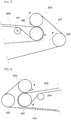
- the integral type washing machine includes a feeding part 100, a first washing part 200, a second washing part 300, a third washing part 400, a rinsing part 500, a dewatering part 600, a discharging part 700 and a water collection tan1e
- FIG. 1 shows a schematic side view for facilitating a clear understanding of configuration of the present disclosure.
- the washing machine may be provided to have a width of a certain length in a plan view in order to wash the large laundry while conveying the large laundry in a fully expanded state or in a half folded state.
- the feeding part 100 includes a feeding conveyor which is provided with a first feeding roller 110, a second feeding roller 120, and a feeding belt 130 which are used to convey the laundry to the first washing part 200.
- the feeding conveyor is operable to convey the laundry to the first washing part 200.
- a roller positioned adjacent to the first washing part 200 will be referred to as the second feeding roller 120.
- the laundry can be conveyed in a direction from the first feeding roller 110 arranged in a horizontal direction or an upwardly-inclined direction toward the second feeding roller 120.
- the first washing part 200 is provided to roughly wash the laundry fed from the feeding part 100.
- the first washing part 200 may include a soaking tank 220 in which the laundries fed from the feeding part 100 are received, a first washing nozzle 210 provided to inject the washing water toward the laundries which are being conveyed to the soaking tank 220, and a detergent tank 230.
- the first washing nozzle 210 is a nozzle that discharges the washing water toward the laundries which are being conveyed from the feeding part 100 to the soaking tank 220.
- the first washing nozzle 210 may include one or more washing nozzles, and may be installed to be inclined in a conveyance direction of the laundries or in an opposite direction thereof, or installed in a direction perpendicular to the laundries to discharge the washing water.
- the laundries may be conveyed in a downwardly-inclined direction by a first conveyor.
- the first conveyor may be installed to connect the first washing part 200 and the second washing part 300. A description thereof will be described later.
- the soaking tank 220 is a bath in which the laundries fed from the feeding part 100 is temporarily received.
- the washing water is stored in the soaking tank 220, and the laundries may be soaked in the washing water.
- a period of time during which the laundries are soaked in the soaking tank 220 depends on a conveyance operation of the first conveyor.
- the laundries may be soaked in the soaking tank 220 for a certain period of time as the first conveyor is ceased for some time. Further, the laundries may be soaked in the soaking tank 220 for a little when the first conveyor continuedly conveys the laundries.
- the detergent tank 230 includes at least one tank for storing detergent to be supplied to the washing water.
- the detergent tank 230 may include tubes or pipes to supply the detergent of the detergent tank 230 to the washing water that is fed from the first washing nozzle 210, a second washing nozzle 320, and a third washing nozzle 410.
- the detergent tank 230 may be provided for each type of detergent. In addition, the detergent tank 230 may be provided for each washing nozzle that supplies the detergent. As an example, different detergents may be applied to the first washing nozzle 210, the second washing nozzle 320, and the third washing nozzle 410. The detergent tank 230 may be provided common to the first washing part 200, the second washing part 300 and the third washing part 400.
- the second washing part 300 is provided to perform a primary washing on the laundries passed through the first washing part 200.
- the second washing part 300 includes a sensor 310 provided to sense the laundries which are being conveyed from the soaking tank 220, at least one or more of the second washing nozzle 320 arranged to discharge the washing water containing the detergent toward the conveying laundries, and the detergent tank 230.
- the second washing nozzle 320 may include a 2-1st washing nozzle 321 and a 2-2nd washing nozzle 322 which are disposed to be inclined at about 5 to 45 degrees in the conveyance direction of the laundries, and a 2-3rd washing nozzle 323 which is disposed to be inclined at about 5 to 45 degrees in a direction opposite the conveyance direction.
- the 2-1st washing nozzle 321 may be controlled to discharge the washing water after about 2 to 5 seconds.
- the 2-1st washing nozzle 321, the 22nd washing nozzle 322 and the 2-3rd washing nozzle 323 may be arranged in various manners.
- the 2-1st washing nozzle 321 and the 2-3rd washing nozzle 323 may be arranged to discharge the washing water in the same direction
- the 2-2nd washing nozzle 322 may be arranged to discharge the washing water in the reverse direction.
- the 2-1st washing nozzle 321, the 2-2nd washing nozzle 322 and the 2-3rd washing nozzle 323 may be arranged to be similarly inclined at a certain angle in the conveyance direction of the laundries.
- At least one of the washing nozzles may be arranged to be inclined at a certain angle in the reverse direction. In some embodiments, all the washing nozzles may be arranged perpendicular to the laundries. The arrangement and angle of the second washing nozzle 320 as described above is set to achieve the washing of the laundries and the flow of the laundries in an effective manner.
- the first conveyor includes a plurality of rollers and a belt.
- the first conveyor includes a first roller 330 to a seventh roller 336, and a first belt 337.
- the first conveyor will be described with reference to a movement direction of the first belt 337, namely the conveyance direction of the laundries.
- the first belt 337 may be installed to endlessly rotate while being spanned over the first roller 330, the third roller 332, the fourth roller 333, the fifth roller 334, the sixth roller 335, and the seventh roller 336.
- an additional roller may be further installed to apply tension to the first belt 337.
- the first roller 330 and the second roller 331 may be arranged in parallel in the vicinity of the second feeding roller 120 of the feeding conveyer so that the laundries pass through the first roller 330 and the second roller 331 while being sandwiched therebetween.
- the laundries may stably enter the soaking tank 220 between a belt spanned over the first roller 330 and the second roller 331, and a belt by which the second roller 331 and the third roller 332 are driven in an independent interlock relationship with each other as indicated by a dotted line.
- the third roller 332 may be installed inside the soaking tank 220 so that the laundries are completely soaked in the soaking tank 220 and then are taken out from the soaking tank 220.
- the third roller 332 may be provided to switch the travel direction of the first belt 337.
- the fourth roller 333 may be arranged to switch the travel direction of the first belt 337 so that the laundries which pass through the third roller 332 and move quickly upward are conveyed in a horizontal direction or a gentle upward direction.
- the fifth roller 334 may be arranged higher than the fourth roller 333 so that the laundries are conveyed in the horizontal direction or the gentle upward direction.
- the second washing nozzle 320 including at least one nozzle for discharging the washing water toward the laundries that pass through the fourth roller 333 and the fifth roller 334 may be installed.
- the detergent tank 230 and a fabric softener tank 420 may be connected to the second washing nozzle 320.
- the sixth roller 335 and the seventh roller 336 may be installed such that the first belt 337 returns to the first roller 330 to form an infinite trajectory.
- the sixth roller 335 may be located below the fifth roller 334 in the vicinity of the fifth roller 334.
- the seventh roller 336 may be disposed near the first roller 330 or near the third roller 332.
- the sixth roller 335 and the seventh roller 336 may be located at another position other than the aforementioned position as long as the first belt 337 spanned over the fifth roller 334 can return to the first roller 330 without any interference.
- the third washing part 400 is provided to perform a secondary washing on the laundries passed through the second washing part 300.
- the third washing part 400 includes a third washing nozzle 410, the detergent tank 230 and the fabric softener tank 420 which are connected to the third washing nozzle 410, and a second conveyor.
- the third washing nozzle 410 is installed to discharge the washing water containing a detergent or fabric softener toward the laundries that are being conveyed from the second washing part 300 to the rinsing part 500.
- the third washing nozzle 410 includes at least one washing nozzle.
- the third washing nozzle 410 may include a 3-1st washing nozzle 411 and a 3-2nd washing nozzle 412 which are arranged to be inclined at an angle of about 5 to 45 degrees in the conveyance direction of the laundries, and a 3-3rd washing nozzle 413 arranged to be inclined at an angle of about 5 to 45 degrees in a direction opposite the conveyance direction of the laundries.
- the conveyance direction of the laundries conveyed from the second washing part 300 and the conveyance direction of the laundries conveyed from the third washing part 400 are different from each other.
- the washing nozzles may be also arranged in different directions, and may be rearranged in consideration of the inclined direction.
- the 3-1st washing nozzle 411, the 3-2nd washing nozzle 412 and the 3-3rd washing nozzle 413 may be arranged in various manners.
- the 3-1st washing nozzle 411 and the 3-3rd washing nozzle 413 may be arranged so as to discharge the washing water in the same direction
- the 3-2nd washing nozzle 412 may be arranged to discharge the washing water in the reverse direction.
- the 3-1st washing nozzle 411, the 3-2nd washing nozzle 412 and the 3-3rd washing nozzle 413 may be arranged to be inclined similarly at a certain angle in the conveyance direction of the laundries.
- at least one washing nozzle may be arranged to be inclined at a certain angle in a direction opposite the conveyance direction.
- all washing nozzles may be arranged perpendicular to the laundries.
- the detergent tank 230 and the fabric softener tank 420 may include at least one tank. Tubes or pipes may be provided so that the detergent and the fabric softener in the detergent tank 230 and the fabric softener tank 420 are supplied to at least one nozzle of the 3-1st washing nozzle 411 to the 3-3rd washing nozzle 413.
- the detergent tank 230 may be provided for each type of detergent, if necessary.
- the fiber detergent tank 230 may be provided to supply different detergents to respective nozzles.
- the second conveyor is installed to convey the laundries passed through the second washing part 300 and the third washing part 400 toward the rinsing part 500.
- the second conveyor includes a plurality of rollers and a belt.
- the second conveyor include an eighth roller 430 to an 11th roller 433, and a second belt 434.
- the second conveyor will be described with reference to a movement direction of the second belt 434, namely, the conveyance direction of the laundries.
- the second belt 434 may be installed to endlessly rotate while being spanned over the eighth roller 430, the ninth roller 431, the tenth roller 432, and the 11th roller 433.
- the eighth roller 430 is spanned by the second belt 434 and is installed below the fifth roller 334.
- the eighth roller 430 is arranged below the fifth roller 334 in the vicinity of the fifth roller 334 to apply tension with respect to the first belt 337 spanned over the fifth roller 334.
- the ninth roller 431 is provided to apply tension to the second belt 434 spanned over the eighth roller 430.
- the ninth roller 431 may be disposed in the vicinity of the eighth roller 430, or may be disposed at any place between the eighth roller 430 and the tenth roller 432.
- the tenth roller 432 may be disposed higher than the eighth roller 430 so that the laundries are conveyed in the horizontal direction or the gentle upward direction.
- the third washing nozzle 410 including at least one nozzle configured to discharge the washing water toward the laundries passing between the eighth roller 430 and the tenth roller 432 may be installed.
- the 11th roller 433 is disposed in the vicinity of the tenth roller 432.
- the 11th roller 433 may be installed so that the second belt 434 spanned over the tenth roller 432 returns to the eighth roller 430.
- the 11th roller 433 may be disposed at another position other than the above-described position as long as the second belt 434 can return to the eighth roller 430 through the tenth roller 432 without any interference.
- the rinsing part 500 is installed to perform rinsing and dewatering on the laundries passed through the third washing part 400.
- the rinsing part 500 includes at least one rinsing nozzle 510, at least one rinsing roller 520, a lower support 530, and a third conveyor.
- the rinsing nozzle 510 is installed to discharge the rinsing water toward the laundries which are being conveyed from the third washing part 400 to the dewatering part 600.
- One or more of the rinsing nozzles 510 may be installed at predetermined intervals.
- One of the rinsing nozzles 510 may be connected to the fabric softener tank 420.
- the rinsing roller 520 and the lower support 530 is a dewatering member that can squeeze the rinsing water by pressing the laundries passed through the rinsing nozzle 510 from up and down.
- the rinsing roller 520 and the lower support 530 may be positioned at the front or rear side of the rinsing nozzle 510 in the conveyance direction of the laundries.
- the rinsing roller 520 and the lower support 530 may be provided for each rinsing nozzle 510.
- the rinsing roller 520 may be positioned above the third belt 545 and the lower support 530 may be positioned below the third belt 545. Accordingly, the rinsing roller 520 and the lower support 530 may be arranged to squeeze the rinsing water by pressing the laundries which are conveyed while being placed on the third belt 545 from up and down.
- the third conveyor is installed to convey the laundries passed through the third washing part 400 to the dewatering part 600.
- the third conveyor includes a plurality of rollers and a belt.
- the third conveyor includes a 12th roller 540, a 13th roller 541, a 14th roller 542, a 15th roller 543, a 16th roller 544 and a third belt 545.
- the third conveyor will be described with reference to the movement direction of the third belt 545, namely the conveyance direction of the laundries.
- the third belt 545 may be installed to endlessly rotate while being spanned over the 12th roller 540, the 13th roller 541, the 14th roller 542, the 15th roller 543, and the 16th roller 544.
- the 12th roller 540 is spanned with the third belt 545, and is installed below the 11th roller 433.
- the 12th roller 540 is located below the 11th roller 433 in the vicinity of the 11th roller 433.
- the 12th roller 540 may be arranged to apply tension to the third belt 545 spanned over the 12th roller 540. With this arrangement, the laundries that are being conveyed to the 11th roller 433 while being placed on the second belt 434 pass between the 11th roller 433 and the 12 roller 540, are naturally placed on the third belt 545 and are conveyed along the third belt 545.
- the 13th roller 541 may be arranged higher than the 12th roller 540 so that the laundries are conveyed in the horizontal direction or the gentle upward direction.
- at least one rinsing nozzle 510 may be installed to discharge the rinsing water toward the laundries passing between the 12th roller 540 and the 13th roller 541.
- the 13th roller 541 may be included as one of the components for dewatering the laundries together with the 14 roller 542. Details thereof will be described later.
- the 14th roller 542 is disposed in the vicinity of the 13th roller 541.
- the 14th roller 542 may be installed such that the third belt 545 returns to the 12th roller 540 while spanning over the 14th roller 542.
- the 14th roller 542 may be disposed parallel to the 13th roller 541.
- the 15th roller 543 and the 16th roller 544 are disposed in the vicinity of the 13th roller 541 and the 12th roller 540, respectively.
- the 15th roller 543 may be arranged to apply tension to the third belt 545 spanned over the 14th roller 542, and the 16th roller 544 may be arranged to apply tension to the third belt 545 returning to the 12th roller 540.
- only one of the 15 roller 543 and the 16 roller 544 may be installed.
- the 15 roller 543 and the 16 roller 544 may be disposed anywhere between the 12th roller 540 and the 14 roller 542.
- the dewatering part 600 is installed to compress and dewater the laundries passed through the rinsing part 500.
- the dewatering part 600 includes at least one dewatering roller 610.
- the dewatering roller 610 is positioned above the 13th roller 541 and/or the 14th roller 542.
- the dewatering roller 610 is disposed close to the 13 roller 541, and is provided so as to strongly squeeze the laundries passing therethrough while being placed on the third belt 545 from up and down, in cooperation with the 13th roller 541.
- the dewatering roller 610 may be provided to be linked to the 14 roller 542.
- Dewatering rollers may be additionally provided so that the laundries pass above and below the third belt 545.
- the discharging part 700 is provided with a discharge conveyor including a first discharge roller 710, a second discharge roller 720 and a discharge belt 730 to discharge the laundries passed through the dewatering part 600.
- a discharge roller 710 a roller positioned close to the rinsing part 500 will be referred to as the first discharge roller 710.
- the laundries may be conveyed from the first discharge roller 710 and the second discharge roller 720 which are arranged in a horizontal direction or in a downwardly-inclined direction.
- the discharging part 700 may have an additional configuration for drying the laundries passed through the dewatering part 600.
- the discharging part 700 may further include a hot air blower provided to blow hot air toward the laundries passed through the dewatering part 600.
- an additional drying part may be disposed between the dewatering part 600 and the discharging part 700.
- a drying apparatus including the hot air blower and the additional drying part may be provided.
- the water collection tank includes a first water collection tank 800, a second water collection tank 810 and a third water collection tank 820. These water collection tanks may be connected to each other or may be installed to be in communication with at least one of the dewatering part 600, the rinsing part 500, the third washing part 400, the second washing part 300 and the first washing part 200.
- the first water collection tank 800 is installed to collect the water discharged from the dewatering part 600.
- the collected water of the first water collection tank 800 may be used as the rinsing water of the rinsing part 500, or may be reused as the washing water of at least one of the third washing part 400, the second washing part 300 and the first washing part 200.
- the first water collection tank 800 may include at least one nozzle of the rinsing nozzle 510, the third washing nozzle 410, the second washing nozzle 320, the first washing nozzle 210 and the soaking tank 220, or additional tubes or pipes configured to supply the collected water of the first water collection tank 800.
- the second water collection tank 810 is installed to collect water discharged from the rinsing part 500.
- the collected water of the second water collection tank 810 may be reused as the washing water of at least one of the third washing part 400, the second washing part 300 and the first washing part 200.
- the second water collection tank 810 may include at least one nozzle of the third washing nozzle 410, the second washing nozzle 320, the first washing nozzle 210 and the soaking tank 220, or additional tubes or pipes configured to supply the collected water of the second water collection tank 810.
- the third water collection tank 820 is installed to collect water discharged from the third washing part 400 or the second washing part 300.
- the collected water of the third water collection tank 820 may be reused in the first washing part 200.
- the third water collection tank 820 may include additional tubes or pipes configured to supply the collected water to the first washing nozzle 210 and the soaking tank 220.
- the water discharged from the dewatering part 600 is collected in the first water collection tank 800, and subsequently, is supplied to the rinsing nozzle 510 of the rinsing part 500.
- the water discharged from the rinsing part 500 is collected in the second water collection tank 810, and subsequently, is supplied to the third washing nozzle 410 of the third washing part 400 and the second washing nozzle 320 of the second washing part 300.
- the water discharged from the third washing part 400 and the second washing part 300 is collected in the third water collection tank 820, and subsequently, is supplied to the first washing nozzle 210 of the first washing part 200 and the soaking tank 220. Thereafter, the water may be treated as wastewater.
- the present disclosure it is possible to reduce water consumption to approximately 50% or less by reusing the water discharged in each process, compared with the case of treating, as the wastewater, the water discharged in the washing, rinsing and dewatering processes as in the related art. More specifically, in the related art, in a case in which 120 bed sheets are washed by a washing machine having a capability of 100kg, all the water of 500L used in a washing step, the water of 500 L used in a rinsing step (repeated two or three times), and the water of 500L used in a dewatering step are treated as the wastewater. As a result, a total of 1.5 to 2 tons of water was consumed. On the other hand, in the case of using the apparatus of the present disclosure, the water is recycled during the washing, rinsing and dewatering steps, and the wastewater treatment is performed once. This makes it possible to save the water consumption to approximately 50% or less.
Landscapes
- Engineering & Computer Science (AREA)
- Textile Engineering (AREA)
- Accessory Of Washing/Drying Machine, Commercial Washing/Drying Machine, Other Washing/Drying Machine (AREA)
- Cleaning By Liquid Or Steam (AREA)
- Treatment Of Fiber Materials (AREA)
- Detail Structures Of Washing Machines And Dryers (AREA)
Applications Claiming Priority (2)
| Application Number | Priority Date | Filing Date | Title |
|---|---|---|---|
| KR1020170056042A KR101864713B1 (ko) | 2017-05-02 | 2017-05-02 | 일체형 세탁장치 |
| PCT/KR2018/005042 WO2018203644A1 (ko) | 2017-05-02 | 2018-05-01 | 일체형 세탁장치 |
Publications (1)
| Publication Number | Publication Date |
|---|---|
| EP3620565A1 true EP3620565A1 (de) | 2020-03-11 |
Family
ID=62635462
Family Applications (1)
| Application Number | Title | Priority Date | Filing Date |
|---|---|---|---|
| EP18793758.6A Withdrawn EP3620565A1 (de) | 2017-05-02 | 2018-05-01 | Integrierte waschvorrichtung |
Country Status (6)
| Country | Link |
|---|---|
| US (1) | US20200056319A1 (de) |
| EP (1) | EP3620565A1 (de) |
| JP (1) | JP2020518425A (de) |
| KR (1) | KR101864713B1 (de) |
| CN (1) | CN110832131A (de) |
| WO (1) | WO2018203644A1 (de) |
Families Citing this family (1)
| Publication number | Priority date | Publication date | Assignee | Title |
|---|---|---|---|---|
| CN120463828A (zh) * | 2023-08-04 | 2025-08-12 | 安徽森淼实业有限公司 | 一种自动化连续式羟丙基甲基纤维素洗涤装置 |
Family Cites Families (25)
| Publication number | Priority date | Publication date | Assignee | Title |
|---|---|---|---|---|
| JPS5161180A (en) * | 1974-07-23 | 1976-05-27 | Kihei Saito | Sendakuhohoto sonosendakusochi |
| JPS52137161A (en) * | 1976-05-11 | 1977-11-16 | Asahi Chem Ind Co Ltd | Cleaning device |
| JPS552450A (en) * | 1978-06-21 | 1980-01-09 | Mitsubishi Electric Corp | Washing machine |
| JPS59168164A (ja) * | 1983-03-16 | 1984-09-21 | 塚本 和子 | 布洗浄方法及び装置 |
| JPS6257593A (ja) * | 1986-02-21 | 1987-03-13 | 浪内 敬一郎 | 布団の洗濯装置 |
| JP3175855B2 (ja) * | 1992-03-18 | 2001-06-11 | ワイエイシイ株式会社 | 産業用クリーニング装置 |
| JP3175858B2 (ja) * | 1992-06-11 | 2001-06-11 | ワイエイシイ株式会社 | 産業用クリーニング装置 |
| JPH06104160B2 (ja) * | 1992-12-01 | 1994-12-21 | 陽一 立花 | 連続式クリーニング装置 |
| JP2680783B2 (ja) * | 1994-07-14 | 1997-11-19 | 昭和金属工業株式会社 | コインの洗浄装置 |
| US5728977A (en) * | 1996-04-09 | 1998-03-17 | Juday; Thomas W. | Apparatus and methods for determining the quantity of and stabilizing a plurality of soiled industrial towels |
| JPH10296202A (ja) * | 1997-04-25 | 1998-11-10 | Ishikawajima Harima Heavy Ind Co Ltd | マット洗浄装置 |
| KR20000007315A (ko) * | 1998-07-02 | 2000-02-07 | 구자홍 | 분무/흡입형 세탁기 |
| KR200201492Y1 (ko) * | 2000-05-25 | 2000-11-01 | 권덕진 | 자동타월세탁장치 |
| JP2002282573A (ja) * | 2001-03-23 | 2002-10-02 | Yasushi Ito | 洗濯機およびその使用方法 |
| US7497099B2 (en) * | 2003-10-06 | 2009-03-03 | Star Cluster Co., Ltd. | Ultrasonic washing method for clothes |
| WO2006103700A1 (en) | 2005-03-28 | 2006-10-05 | Sanjiv Agarwal | Tandem washing machines configuration for recycling detergent & water |
| KR100822644B1 (ko) | 2006-06-27 | 2008-04-16 | 후소특장(주) | 세탁물의 살균 및 세척을 위한 방법 및 그 장치 |
| KR100868337B1 (ko) * | 2007-05-16 | 2008-11-12 | 김태우 | 벨트프레스형 슬러지 탈수기 |
| KR100952357B1 (ko) * | 2007-12-13 | 2010-04-09 | 이광민 | 와이셔츠의 칼라 및 소매 전용세탁기 |
| CN201275920Y (zh) * | 2008-08-25 | 2009-07-22 | 上海坚新机电设备有限公司 | 节水型导带水洗装置 |
| KR20100118495A (ko) * | 2009-04-28 | 2010-11-05 | 주성기 | 라텍스 쿠션물 제조설비의 세척 및 탈수장치 |
| JP5708274B2 (ja) * | 2011-06-06 | 2015-04-30 | シブヤマシナリー株式会社 | 洗浄装置 |
| CN104246989B (zh) * | 2012-06-14 | 2016-08-17 | 夏普株式会社 | 药液处理装置 |
| JP6258892B2 (ja) * | 2014-05-13 | 2018-01-10 | 芝浦メカトロニクス株式会社 | 基板処理装置及び基板処理方法 |
| CN204563703U (zh) * | 2015-01-09 | 2015-08-19 | 四川大学 | 用于清洗压滤机滤布的装置 |
-
2017
- 2017-05-02 KR KR1020170056042A patent/KR101864713B1/ko not_active Expired - Fee Related
-
2018
- 2018-05-01 JP JP2020512346A patent/JP2020518425A/ja active Pending
- 2018-05-01 CN CN201880044530.2A patent/CN110832131A/zh active Pending
- 2018-05-01 US US16/610,422 patent/US20200056319A1/en not_active Abandoned
- 2018-05-01 EP EP18793758.6A patent/EP3620565A1/de not_active Withdrawn
- 2018-05-01 WO PCT/KR2018/005042 patent/WO2018203644A1/ko not_active Ceased
Also Published As
| Publication number | Publication date |
|---|---|
| WO2018203644A1 (ko) | 2018-11-08 |
| CN110832131A (zh) | 2020-02-21 |
| KR101864713B1 (ko) | 2018-06-05 |
| US20200056319A1 (en) | 2020-02-20 |
| JP2020518425A (ja) | 2020-06-25 |
Similar Documents
| Publication | Publication Date | Title |
|---|---|---|
| TWI722894B (zh) | 水洗機 | |
| CN104862906B (zh) | 全松式、连续化浸染增白生产线及其织物增白或固色整理生产工艺 | |
| US7392558B2 (en) | Method and apparatus for cleaning sails | |
| CN104420088B (zh) | 用于清洗织物的装置和方法 | |
| KR101890922B1 (ko) | 원단 전처리 가공장치 | |
| JP2021058612A (ja) | 連続バッチ式トンネル型洗濯機で洗濯する方法 | |
| EP3620565A1 (de) | Integrierte waschvorrichtung | |
| CN206882219U (zh) | 一种多功能的地毯面料清洗装置 | |
| JPH06170100A (ja) | 連続式クリーニング装置 | |
| CN101305121B (zh) | 用于连续处理绳状织物的机器和相关方法 | |
| CN201495396U (zh) | 喷射式给液机 | |
| CN209243371U (zh) | 染色后水洗机 | |
| JP5139691B2 (ja) | 洗濯物の洗濯乾燥システム | |
| US20200165763A1 (en) | Washing machine capable of performing normal washing and intense washing | |
| CN105908423A (zh) | 一种纺织用纺织面料退浆装置 | |
| KR102055619B1 (ko) | 수세부가 구비되는 원단 열처리 가공기 | |
| EP3983593B1 (de) | Verfahren zum kontinuierlichen breitwaschen von geweben | |
| CN211772025U (zh) | 一种多u型槽水洗机 | |
| KR101805357B1 (ko) | 노즐을 구비한 세탁물 이송장치 | |
| CN208328377U (zh) | 纺织布料生产的定型除油装置 | |
| US1487914A (en) | Washing process and machine | |
| CN105200690B (zh) | 一种连续式散纤维加工设备 | |
| CN105088589B (zh) | 一种连续式散纤维后处理设备 | |
| JPH01174665A (ja) | 布帛の連続洗浄装置 | |
| EP2455530A1 (de) | Verfahren und Vorrichtung zur Behandlung, insbesondere Nassbehandlung von Wäsche |
Legal Events
| Date | Code | Title | Description |
|---|---|---|---|
| STAA | Information on the status of an ep patent application or granted ep patent |
Free format text: STATUS: THE INTERNATIONAL PUBLICATION HAS BEEN MADE |
|
| PUAI | Public reference made under article 153(3) epc to a published international application that has entered the european phase |
Free format text: ORIGINAL CODE: 0009012 |
|
| STAA | Information on the status of an ep patent application or granted ep patent |
Free format text: STATUS: REQUEST FOR EXAMINATION WAS MADE |
|
| 17P | Request for examination filed |
Effective date: 20191119 |
|
| AK | Designated contracting states |
Kind code of ref document: A1 Designated state(s): AL AT BE BG CH CY CZ DE DK EE ES FI FR GB GR HR HU IE IS IT LI LT LU LV MC MK MT NL NO PL PT RO RS SE SI SK SM TR |
|
| AX | Request for extension of the european patent |
Extension state: BA ME |
|
| DAV | Request for validation of the european patent (deleted) | ||
| DAX | Request for extension of the european patent (deleted) | ||
| STAA | Information on the status of an ep patent application or granted ep patent |
Free format text: STATUS: THE APPLICATION IS DEEMED TO BE WITHDRAWN |
|
| 18D | Application deemed to be withdrawn |
Effective date: 20201201 |