EP3620567A1 - Lave-linge à tambour à chargement par le dessus et dispositif de positionnement associé - Google Patents
Lave-linge à tambour à chargement par le dessus et dispositif de positionnement associé Download PDFInfo
- Publication number
- EP3620567A1 EP3620567A1 EP18794135.6A EP18794135A EP3620567A1 EP 3620567 A1 EP3620567 A1 EP 3620567A1 EP 18794135 A EP18794135 A EP 18794135A EP 3620567 A1 EP3620567 A1 EP 3620567A1
- Authority
- EP
- European Patent Office
- Prior art keywords
- washing machine
- pulley
- locking
- disposed
- positioning device
- Prior art date
- Legal status (The legal status is an assumption and is not a legal conclusion. Google has not performed a legal analysis and makes no representation as to the accuracy of the status listed.)
- Granted
Links
Images
Classifications
-
- D—TEXTILES; PAPER
- D06—TREATMENT OF TEXTILES OR THE LIKE; LAUNDERING; FLEXIBLE MATERIALS NOT OTHERWISE PROVIDED FOR
- D06F—LAUNDERING, DRYING, IRONING, PRESSING OR FOLDING TEXTILE ARTICLES
- D06F37/00—Details specific to washing machines covered by groups D06F21/00 - D06F25/00
- D06F37/30—Driving arrangements
- D06F37/302—Automatic drum positioning
-
- D—TEXTILES; PAPER
- D06—TREATMENT OF TEXTILES OR THE LIKE; LAUNDERING; FLEXIBLE MATERIALS NOT OTHERWISE PROVIDED FOR
- D06F—LAUNDERING, DRYING, IRONING, PRESSING OR FOLDING TEXTILE ARTICLES
- D06F23/00—Washing machines with receptacles, e.g. perforated, having a rotary movement, e.g. oscillatory movement, the receptacle serving both for washing and for centrifugally separating water from the laundry
- D06F23/02—Washing machines with receptacles, e.g. perforated, having a rotary movement, e.g. oscillatory movement, the receptacle serving both for washing and for centrifugally separating water from the laundry and rotating or oscillating about a horizontal axis
- D06F23/025—Washing machines with receptacles, e.g. perforated, having a rotary movement, e.g. oscillatory movement, the receptacle serving both for washing and for centrifugally separating water from the laundry and rotating or oscillating about a horizontal axis with a rotatable imperforate tub
-
- D—TEXTILES; PAPER
- D06—TREATMENT OF TEXTILES OR THE LIKE; LAUNDERING; FLEXIBLE MATERIALS NOT OTHERWISE PROVIDED FOR
- D06F—LAUNDERING, DRYING, IRONING, PRESSING OR FOLDING TEXTILE ARTICLES
- D06F34/00—Details of control systems for washing machines, washer-dryers or laundry dryers
- D06F34/04—Signal transfer or data transmission arrangements
-
- D—TEXTILES; PAPER
- D06—TREATMENT OF TEXTILES OR THE LIKE; LAUNDERING; FLEXIBLE MATERIALS NOT OTHERWISE PROVIDED FOR
- D06F—LAUNDERING, DRYING, IRONING, PRESSING OR FOLDING TEXTILE ARTICLES
- D06F34/00—Details of control systems for washing machines, washer-dryers or laundry dryers
- D06F34/14—Arrangements for detecting or measuring specific parameters
-
- D—TEXTILES; PAPER
- D06—TREATMENT OF TEXTILES OR THE LIKE; LAUNDERING; FLEXIBLE MATERIALS NOT OTHERWISE PROVIDED FOR
- D06F—LAUNDERING, DRYING, IRONING, PRESSING OR FOLDING TEXTILE ARTICLES
- D06F37/00—Details specific to washing machines covered by groups D06F21/00 - D06F25/00
- D06F37/30—Driving arrangements
-
- D—TEXTILES; PAPER
- D06—TREATMENT OF TEXTILES OR THE LIKE; LAUNDERING; FLEXIBLE MATERIALS NOT OTHERWISE PROVIDED FOR
- D06F—LAUNDERING, DRYING, IRONING, PRESSING OR FOLDING TEXTILE ARTICLES
- D06F2103/00—Parameters monitored or detected for the control of domestic laundry washing machines, washer-dryers or laundry dryers
- D06F2103/24—Spin speed; Drum movements
-
- D—TEXTILES; PAPER
- D06—TREATMENT OF TEXTILES OR THE LIKE; LAUNDERING; FLEXIBLE MATERIALS NOT OTHERWISE PROVIDED FOR
- D06F—LAUNDERING, DRYING, IRONING, PRESSING OR FOLDING TEXTILE ARTICLES
- D06F23/00—Washing machines with receptacles, e.g. perforated, having a rotary movement, e.g. oscillatory movement, the receptacle serving both for washing and for centrifugally separating water from the laundry
- D06F23/02—Washing machines with receptacles, e.g. perforated, having a rotary movement, e.g. oscillatory movement, the receptacle serving both for washing and for centrifugally separating water from the laundry and rotating or oscillating about a horizontal axis
Definitions
- the present disclosure belongs to the field of laundry washing equipment, and particularly relates to a top load drum washing machine and a positioning device thereof.
- drum washing machines are of a side door type which, however, requires a user to bend his/her body or squat down during use to put laundries into the drum via the side door of the washing machine or take out the laundries from the drum via the side door, thereby having an influence on the user's experience during use (especially for the elderly).
- top load drum washing machines (such as the drum washing machine disclosed in the application documents of Chinese patent No. CN1244730C ) have emerged as the time requires.
- the drum is also provided with a drum door in a circumferential direction, and the drum is locked by a drum locking device when the washing machine stops rotating and the drum door corresponds to the top door of the washing machine.
- the locking of the drum by the drum locking device is achieved by inserting a locking tongue of the drum locking device into a groove of a pulley.
- the groove corresponding to the locking tongue is usually disposed on a rim of the pulley, and an edge of a notch of the groove will cause a certain degree of wear on the belt during operation of the washing machine. If the edge of the groove has sharp burrs, the belt may even be cut, which reduces service life of the belt and increases a failure rate of the washing machine.
- a positioning device for a top load drum washing machine is provided by the present disclosure, wherein the washing machine includes an outer cylinder, an inner cylinder disposed inside the outer cylinder and a pulley connected to the inner cylinder; the positioning device includes: a locking structure disposed on a spoke of the pulley; and a locking device disposed on the outer cylinder, the locking device including a lock body and a locking tongue; a position of the locking device corresponds to a rotational path of the locking structure so that when the inner cylinder stops rotating, the locking tongue is capable of forming a locking engagement with the locking structure.
- the locking structure is a groove disposed on the spoke.
- the locking tongue is a rocker type locking tongue, one end of which is connected to the lock body.
- the positioning device further includes a detecting device configured to detect a rotational position of the inner cylinder.
- the detecting device includes a signal transmitting device and a signal receiving device, the signal transmitting device is disposed on the pulley, and the signal receiving device is disposed on the outer cylinder or on a body of the washing machine.
- the signal transmitting device is disposed on a rim of the pulley.
- the detecting device includes a signal transmitting device and a signal receiving device, the signal transmitting device is disposed on the outer cylinder or a body of the washing machine, and the signal receiving device is disposed on the pulley.
- the signal transmitting device is a magnet
- the signal receiving device is a Hall element
- a top load drum washing machine is provided by the present disclosure, which includes the positioning device according to any one of the above technical solutions.
- the belt on the pulley can be prevented from contacting interfaces of the locking structure, thus avoiding wear of the belt and increasing the service life of the belt.
- the locking structure corresponding to the locking device is disposed on one spoke of the pulley in the present disclosure. Therefore, by changing the position of the locking structure in the lengthwise direction of the spoke, more choice on position of the locking device fixed to the outer cylinder in the lengthwise direction of the spoke are made available. Moreover, since the pulley has a plurality of spokes, the locking device can be disposed at any projection position of each spoke on the outer cylinder as long as the position of the drum door of the inner cylinder can correspond to the position of the washing machine door.
- the lock tongue of the locking device is configured to have a rocker type structure, and the rocker type lock tongue has a smaller thickness in the axis direction of the pulley so that the locking device has a smaller thickness in the axis direction of the pulley when the rocker type lock tongue is received into the lock body. Therefore, when the rocker type lock tongue is received into the lock body, the locking device fixed to the outer cylinder will not come into contact with the rotating pulley, making the structure very compact.
- the top load drum washing machine of the present disclosure mainly includes an outer cylinder, an inner cylinder, a positioning device, a pulley, and a motor for driving the pulley to rotate.
- the inner cylinder is disposed inside the outer cylinder, one end of the inner cylinder is coaxially fixed to the pulley, and the motor drives the pulley to rotate via a belt.
- a washing machine door of the drum washing machine of the present disclosure is disposed at the top of the drum washing machine, and the inner cylinder is provided with a side-open drum door corresponding to the washing machine door.
- the inner cylinder stops rotating and the drum door faces upward, the inner cylinder is locked by the positioning device, and the user can put laundries into the inner cylinder via the washing machine door or the drum door, or take out the laundries from the inner cylinder via the washing machine door or the drum door.
- the positioning device of the present disclosure includes a locking device 1 and a detecting device.
- the locking device 1 is mainly composed of a lock body 11 and a lock tongue 12.
- the lock body 11 is fixed to the outer cylinder, and the lock tongue 12 is capable of abutting against a pulley 2 when it protrudes from the lock body 11.
- one spoke 21 of the pulley 2 is provided with a locking structure (not shown) capable of accommodating the lock tongue 12. After the lock tongue 12 protrudes from the lock body 11, one end of the lock tongue 12 can be captured into the locking structure, and the locking device 1 can lock the pulley 2 through the lock tongue 12 so that the inner cylinder coaxially fixed to the pulley 2 is locked.
- the lock tongue 12 is a rocker type lock tongue having a sheet-like structure, and when the lock tongue 12 is received into the lock body 1, a thickness direction of the lock tongue 12 is parallel or substantially parallel to an axis of the pulley 2.
- One end of the lock tongue 12 is pivotally connected to the lock body 11, and the other end of the lock tongue 12 can be rotated out of or into the lock body 11 around the pivotal joint of the lock tongue 12 and the lock body 11.
- a driving device for driving the lock tongue 12 to rotate may be a micro motor disposed inside the lock body 11.
- the micro motor is connected to a pivotal end of the lock tongue 12, and when the micro motor rotates, the lock tongue 12 can be driven by a gear or belt to rotate so that the lock tongue 12 rotates out of or into the lock body 11.
- a cam is fixed on an output shaft of the micro motor, and the micro motor is capable of pushing out a free end of the lock tongue 12 via the cam.
- the micro motor drives the cam to rotate to the original position, and the lock tongue 12 is pulled into the lock body 11 by a spring disposed in the lock body 11.
- those skilled in the art may also anticipate rotating the free end of the lock tongue 12 out of or into the lock body 11 by other feasible driving means such as a solenoid valve.
- the lock tongue 12 of the above structure also enables the lock body 11 to have a thinner structure. Therefore, when the locking device 1 is fixed to the outer cylinder and the locking tongue 12 is received into the lock body 1, no part of the locking device 1 will come into contact with the pulley 2. Therefore, the locking device 1 of the present disclosure can make full use of the space between the pulley 2 and the outer cylinder.
- the locking structure is a groove disposed on one spoke 21 of the pulley 2, in order to prevent the free end of the lock tongue 12 from protruding so long as beyond the other side of the spoke 21 adjacent the inner cylinder.
- those skilled in the art may also anticipate setting the locking structure as a through hole in the spoke 21 of the pulley 2 as needed.
- the detecting device is configured to monitor the position of the drum door, and the detecting device mainly includes a magnet 3 as a signal transmitting device and a Hall element 4 as a signal receiving device.
- the magnet 3 is disposed on the pulley 2
- the Hall element 4 is disposed on the outer cylinder.
- the magnet 3 is disposed on a rim 22 of the pulley 2, and the position of the Hall element 4 on the outer cylinder corresponds to a rotational path of the magnet 3 so that the Hall element 4 is capable of clearly receiving a signal from the magnet 3.
- the rotational path of the magnet 3 is a circular path in which the magnet 3 rotates around the axial center of the pulley 2 by one turn, and the Hall element 4 is located on the circular path. Therefore, the magnet 3 is always capable of reaching a position aligned with the Hall element 4 during one turn of rotation.
- the magnet 3 may be any form of magnets, such as an electromagnetic coil.
- those skilled in the art may also dispose the magnet 3 at other positions on the pulley 2 as needed, such as on the spokes 21.
- those skilled in the art may also dispose the Hall element 4 on the pulley 2, and dispose the magnet 3 on the outer cylinder as needed so that the magnet 3 corresponds to the rotational path of the Hall element 4.
- the rotational path of the Hall element 4 is a circular path in which the Hall element 4 rotates around the axial center of the pulley 2 by one turn, and the magnet 3 is located on the circular path. Therefore, the Hall element 4 is always capable of reaching a position aligned with the magnet 3 during one turn of rotation.
- the detecting device may also be a combination of a light emitting element and a photosensitive sensor, an angle sensor disposed on the pulley 2, and a proximity switch disposed on the pulley 2 or the outer cylinder.
- the top load drum washing machine of the present disclosure further includes a washing machine controller and a motor controller, and the washing machine controller is communicatively connected to the motor controller and the Hall element 4 respectively.
- the washing machine controller is capable of sending an instruction to the motor controller, and after the motor controller receives the instruction, the motor controller is capable of controlling the motor to drive the pulley 2 to rotate.
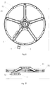
- a locking process of the inner cylinder of the top load drum washing machine of the present disclosure will be described in detail below with reference to FIGS. 1 and 2 .
- the free end of the lock tongue 12 of the locking device 1 is captured into the groove on the spoke 21 of the pulley 2, and the positions of the washing machine door and the drum door coincide or substantially coincide with each other so that the user can put the laundries into the washing machine via the washing machine door and the drum door, or take out the laundries from the inner cylinder of the washing machine via the washing machine door and the drum door.
- the washing machine controller sends an instruction to the motor controller, according to which the motor controller reduces a rotational speed of the motor connected to the pulley 2 and maintains a low-speed operation.
- the Hall element 4 detects the magnet 3
- the Hall element 4 sends a signal to the washing machine controller
- the washing machine controller issues an instruction to the motor controller based on the signal, and the motor controller stops the motor from rotating.
- the washing machine controller issues a motor rotation stop instruction to the motor controller
- the washing machine controller controls the locking device 1 to cause the free end of the lock tongue 12 to be captured into the groove on the spoke 21 of the pulley 2.
- the inner cylinder is therefore locked, at which time the positions of the washing machine door and the drum door coincide or substantially coincide with each other.
- a groove is disposed on one spoke 21 of the pulley 2, and the locking device 1 is disposed on the outer cylinder at a position corresponding to the rotational path of the groove so that the locking device 1 is within a projection area of the pulley 2, the structure of the washing machine is made more compact.
- the rotational path of the groove is a circular path in which the groove rotates around the axial center of the pulley 2 by one turn, and the locking device 1 is located on the circular path. Therefore, the groove is always capable of reaching a position aligned with the locking device 1 during one turn of rotation so that the lock tongue can be inserted into the groove.
- the present disclosure provides a technical solution in which a groove corresponding to the lock tongue 12 of the locking device 1 is disposed on one spoke 21 of the pulley 2. As compared to the technical solution in the existing technology in which the groove is disposed on the rim 22 of the pulley 2, a phenomenon that a notch of the groove contacts the belt on the pulley 2 to wear the belt is avoided.
- the locking structure corresponding to the locking device 1 is disposed on one spoke 21 of the pulley 2 in the present disclosure. Therefore, by changing positions of the locking structure in the lengthwise direction of the spoke 21, more choices on position of the locking device 1 fixed to the outer cylinder in the lengthwise directions of the spokes 21 are made available. Moreover, since the pulley 2 has a plurality of spokes 21, the locking device 1 can be disposed at any projection position of each spoke 21 on the outer cylinder as long as the position of the drum door of the inner cylinder can correspond to the position of the washing machine door, thus further improving choice flexibility of the position of the locking device 1 on the outer cylinder.
Landscapes
- Engineering & Computer Science (AREA)
- Textile Engineering (AREA)
- Computer Networks & Wireless Communication (AREA)
- Main Body Construction Of Washing Machines And Laundry Dryers (AREA)
Applications Claiming Priority (2)
| Application Number | Priority Date | Filing Date | Title |
|---|---|---|---|
| CN201710299649.1A CN107059338B (zh) | 2017-05-02 | 2017-05-02 | 顶开式滚筒洗衣机及其定位装置 |
| PCT/CN2018/086750 WO2018202210A1 (fr) | 2017-05-02 | 2018-05-14 | Lave-linge à tambour à chargement par le dessus et dispositif de positionnement associé |
Publications (3)
| Publication Number | Publication Date |
|---|---|
| EP3620567A1 true EP3620567A1 (fr) | 2020-03-11 |
| EP3620567A4 EP3620567A4 (fr) | 2020-10-21 |
| EP3620567B1 EP3620567B1 (fr) | 2021-09-22 |
Family
ID=59605237
Family Applications (1)
| Application Number | Title | Priority Date | Filing Date |
|---|---|---|---|
| EP18794135.6A Active EP3620567B1 (fr) | 2017-05-02 | 2018-05-14 | Lave-linge à tambour à chargement par le dessus et dispositif de positionnement associé |
Country Status (4)
| Country | Link |
|---|---|
| US (1) | US20210087736A1 (fr) |
| EP (1) | EP3620567B1 (fr) |
| CN (1) | CN107059338B (fr) |
| WO (1) | WO2018202210A1 (fr) |
Families Citing this family (7)
| Publication number | Priority date | Publication date | Assignee | Title |
|---|---|---|---|---|
| CN107059338B (zh) * | 2017-05-02 | 2021-03-12 | 青岛海尔洗衣机有限公司 | 顶开式滚筒洗衣机及其定位装置 |
| CN109518402B (zh) * | 2017-09-18 | 2024-03-26 | 佛山市顺德海尔电器有限公司 | 衣物处理设备及其定位装置 |
| CN110664357B (zh) * | 2018-07-02 | 2021-11-26 | 青岛海尔洗衣机有限公司 | 带轮装置、洗鞋机和用于带轮装置的控制方法 |
| CN110002141A (zh) * | 2019-04-29 | 2019-07-12 | 肇庆市忠良环境卫生管理有限公司 | 一种智能垃圾分类与回收装置 |
| CN112779719A (zh) * | 2019-11-01 | 2021-05-11 | 佛山市云米电器科技有限公司 | 一种洗衣机的减速方法、系统、存储介质及洗衣机 |
| CN115305688A (zh) * | 2021-05-07 | 2022-11-08 | 青岛海尔滚筒洗衣机有限公司 | 一种定位环及洗衣机 |
| CN118166523A (zh) * | 2023-12-26 | 2024-06-11 | 珠海格力电器股份有限公司 | 一种顶开式滚筒洗衣机以及控制方法 |
Family Cites Families (10)
| Publication number | Priority date | Publication date | Assignee | Title |
|---|---|---|---|---|
| EP0073508A1 (fr) * | 1981-09-01 | 1983-03-09 | EATON GmbH & CO. KG | Dispositif d'entraînement, en particulier pour machines à laver |
| DE3738613A1 (de) * | 1987-11-13 | 1989-05-24 | Miele & Cie | Mantelbeschickbare trommelwaschmaschine |
| CN2348183Y (zh) * | 1998-10-18 | 1999-11-10 | 云南杨林实业总公司 | 自定位长颈超轻型多用皮带轮 |
| JP3609789B2 (ja) * | 2002-03-06 | 2005-01-12 | 三洋電機株式会社 | ドラム式洗濯機 |
| ITTO20040691A1 (it) * | 2004-10-08 | 2005-01-08 | Elbi Int Spa | Dispositivo di bloccaggio per un elemento mobile, in particolare per un cestello portabiancheria di una macchina lavatrice a carica dall'alto |
| CN1974912B (zh) * | 2005-11-30 | 2010-08-25 | 海尔集团公司 | 一种滚筒洗衣机的滚筒缓冲定位装置 |
| CN101063270B (zh) * | 2006-04-30 | 2011-05-25 | 海尔集团公司 | 滚筒式洗衣机的内桶定位方法及其装置 |
| CN101729012A (zh) * | 2009-12-18 | 2010-06-09 | 合肥荣事达三洋电器股份有限公司 | 顶开式滚筒洗衣机的准确停机定位的电机装置 |
| CN106480646B (zh) * | 2015-08-31 | 2019-11-12 | 青岛海尔洗衣机有限公司 | 一种内桶的锁止机构及洗衣机 |
| CN107059338B (zh) * | 2017-05-02 | 2021-03-12 | 青岛海尔洗衣机有限公司 | 顶开式滚筒洗衣机及其定位装置 |
-
2017
- 2017-05-02 CN CN201710299649.1A patent/CN107059338B/zh active Active
-
2018
- 2018-05-14 US US16/610,199 patent/US20210087736A1/en not_active Abandoned
- 2018-05-14 WO PCT/CN2018/086750 patent/WO2018202210A1/fr not_active Ceased
- 2018-05-14 EP EP18794135.6A patent/EP3620567B1/fr active Active
Also Published As
| Publication number | Publication date |
|---|---|
| EP3620567B1 (fr) | 2021-09-22 |
| CN107059338A (zh) | 2017-08-18 |
| US20210087736A1 (en) | 2021-03-25 |
| WO2018202210A1 (fr) | 2018-11-08 |
| CN107059338B (zh) | 2021-03-12 |
| EP3620567A4 (fr) | 2020-10-21 |
Similar Documents
| Publication | Publication Date | Title |
|---|---|---|
| EP3620567A1 (fr) | Lave-linge à tambour à chargement par le dessus et dispositif de positionnement associé | |
| CN107059337B (zh) | 定位装置和包括该定位装置的洗衣机 | |
| JP6101511B2 (ja) | ステッピングモータ及びそれを用いた電動弁 | |
| US20120137738A1 (en) | Washing machine | |
| KR102185388B1 (ko) | 인히비터 통합형 액추에이터 변속제어장치 | |
| US20170145611A1 (en) | Clutch device for washing machine and washing machine | |
| WO2015072397A1 (fr) | Embrayage et machine à laver | |
| CN207391824U (zh) | 衣物处理设备及其定位装置 | |
| JP6271784B2 (ja) | ステッピングモータ及びそれを用いた電動弁 | |
| KR101700763B1 (ko) | 세탁기 | |
| US20120024126A1 (en) | Blade driving device and optical apparatus | |
| CN109518402B (zh) | 衣物处理设备及其定位装置 | |
| CN107190469B (zh) | 洗衣机滚筒的定位装置和滚筒洗衣机 | |
| EP1911988A1 (fr) | Dispositif d' entrainement | |
| KR20190009996A (ko) | 세탁기의 세탁과 탈수작동 변환장치 | |
| CN207391830U (zh) | 顶开式衣物处理设备及其定位装置 | |
| CN109385836B (zh) | 顶开式衣物处理设备及其定位装置 | |
| JP4916488B2 (ja) | ドビーのシフト・クラッチのための制御装置 | |
| WO2020083022A1 (fr) | Ensemble formant console de commande d'appareil électroménager | |
| KR20160114926A (ko) | 세탁기용 구동 장치 | |
| CN111585338B (zh) | 一种指示机构及其双电源自动转换开关 | |
| CN105099029A (zh) | 磁环组件、转子组件、电机及洗衣机 | |
| US7955009B2 (en) | Sector blade driving apparatus | |
| US236656A (en) | Clutch for loose pulleys on sewing-machines | |
| JP2000271387A (ja) | 脱水兼用洗濯機 |
Legal Events
| Date | Code | Title | Description |
|---|---|---|---|
| STAA | Information on the status of an ep patent application or granted ep patent |
Free format text: STATUS: THE INTERNATIONAL PUBLICATION HAS BEEN MADE |
|
| PUAI | Public reference made under article 153(3) epc to a published international application that has entered the european phase |
Free format text: ORIGINAL CODE: 0009012 |
|
| STAA | Information on the status of an ep patent application or granted ep patent |
Free format text: STATUS: REQUEST FOR EXAMINATION WAS MADE |
|
| 17P | Request for examination filed |
Effective date: 20191120 |
|
| AK | Designated contracting states |
Kind code of ref document: A1 Designated state(s): AL AT BE BG CH CY CZ DE DK EE ES FI FR GB GR HR HU IE IS IT LI LT LU LV MC MK MT NL NO PL PT RO RS SE SI SK SM TR |
|
| AX | Request for extension of the european patent |
Extension state: BA ME |
|
| XX | Miscellaneous (additional remarks) |
Free format text: THE FILING DATE OF THE INTERNATIONAL APPLICATION IS WITHIN TWO MONTHS FROM THE DATE OF EXPIRATION OF THE PRIORITY PERIOD (R. 26BIS.3 PCT). |
|
| DAV | Request for validation of the european patent (deleted) | ||
| DAX | Request for extension of the european patent (deleted) | ||
| A4 | Supplementary search report drawn up and despatched |
Effective date: 20200922 |
|
| RIC1 | Information provided on ipc code assigned before grant |
Ipc: D06F 37/30 20200101AFI20200916BHEP Ipc: D06F 37/24 20060101ALI20200916BHEP |
|
| GRAP | Despatch of communication of intention to grant a patent |
Free format text: ORIGINAL CODE: EPIDOSNIGR1 |
|
| STAA | Information on the status of an ep patent application or granted ep patent |
Free format text: STATUS: GRANT OF PATENT IS INTENDED |
|
| RIC1 | Information provided on ipc code assigned before grant |
Ipc: D06F 23/02 20060101ALN20210408BHEP Ipc: D06F 37/24 20060101ALI20210408BHEP Ipc: D06F 37/30 20200101AFI20210408BHEP |
|
| INTG | Intention to grant announced |
Effective date: 20210506 |
|
| GRAS | Grant fee paid |
Free format text: ORIGINAL CODE: EPIDOSNIGR3 |
|
| GRAA | (expected) grant |
Free format text: ORIGINAL CODE: 0009210 |
|
| STAA | Information on the status of an ep patent application or granted ep patent |
Free format text: STATUS: THE PATENT HAS BEEN GRANTED |
|
| AK | Designated contracting states |
Kind code of ref document: B1 Designated state(s): AL AT BE BG CH CY CZ DE DK EE ES FI FR GB GR HR HU IE IS IT LI LT LU LV MC MK MT NL NO PL PT RO RS SE SI SK SM TR |
|
| REG | Reference to a national code |
Ref country code: GB Ref legal event code: FG4D |
|
| XX | Miscellaneous (additional remarks) |
Free format text: THE FILING DATE OF THE INTERNATIONAL APPLICATION IS WITHIN TWO MONTHS FROM THE DATE OF EXPIRATION OF THE PRIORITY PERIOD (R. 26BIS.3 PCT). |
|
| REG | Reference to a national code |
Ref country code: IE Ref legal event code: FG4D |
|
| REG | Reference to a national code |
Ref country code: DE Ref legal event code: R096 Ref document number: 602018024028 Country of ref document: DE |
|
| REG | Reference to a national code |
Ref country code: CH Ref legal event code: EP Ref country code: AT Ref legal event code: REF Ref document number: 1432417 Country of ref document: AT Kind code of ref document: T Effective date: 20211015 |
|
| REG | Reference to a national code |
Ref country code: LT Ref legal event code: MG9D |
|
| REG | Reference to a national code |
Ref country code: NL Ref legal event code: MP Effective date: 20210922 |
|
| PG25 | Lapsed in a contracting state [announced via postgrant information from national office to epo] |
Ref country code: NO Free format text: LAPSE BECAUSE OF FAILURE TO SUBMIT A TRANSLATION OF THE DESCRIPTION OR TO PAY THE FEE WITHIN THE PRESCRIBED TIME-LIMIT Effective date: 20211222 Ref country code: LT Free format text: LAPSE BECAUSE OF FAILURE TO SUBMIT A TRANSLATION OF THE DESCRIPTION OR TO PAY THE FEE WITHIN THE PRESCRIBED TIME-LIMIT Effective date: 20210922 Ref country code: BG Free format text: LAPSE BECAUSE OF FAILURE TO SUBMIT A TRANSLATION OF THE DESCRIPTION OR TO PAY THE FEE WITHIN THE PRESCRIBED TIME-LIMIT Effective date: 20211222 Ref country code: RS Free format text: LAPSE BECAUSE OF FAILURE TO SUBMIT A TRANSLATION OF THE DESCRIPTION OR TO PAY THE FEE WITHIN THE PRESCRIBED TIME-LIMIT Effective date: 20210922 Ref country code: SE Free format text: LAPSE BECAUSE OF FAILURE TO SUBMIT A TRANSLATION OF THE DESCRIPTION OR TO PAY THE FEE WITHIN THE PRESCRIBED TIME-LIMIT Effective date: 20210922 Ref country code: HR Free format text: LAPSE BECAUSE OF FAILURE TO SUBMIT A TRANSLATION OF THE DESCRIPTION OR TO PAY THE FEE WITHIN THE PRESCRIBED TIME-LIMIT Effective date: 20210922 Ref country code: FI Free format text: LAPSE BECAUSE OF FAILURE TO SUBMIT A TRANSLATION OF THE DESCRIPTION OR TO PAY THE FEE WITHIN THE PRESCRIBED TIME-LIMIT Effective date: 20210922 |
|
| REG | Reference to a national code |
Ref country code: AT Ref legal event code: MK05 Ref document number: 1432417 Country of ref document: AT Kind code of ref document: T Effective date: 20210922 |
|
| PG25 | Lapsed in a contracting state [announced via postgrant information from national office to epo] |
Ref country code: LV Free format text: LAPSE BECAUSE OF FAILURE TO SUBMIT A TRANSLATION OF THE DESCRIPTION OR TO PAY THE FEE WITHIN THE PRESCRIBED TIME-LIMIT Effective date: 20210922 Ref country code: GR Free format text: LAPSE BECAUSE OF FAILURE TO SUBMIT A TRANSLATION OF THE DESCRIPTION OR TO PAY THE FEE WITHIN THE PRESCRIBED TIME-LIMIT Effective date: 20211223 |
|
| PG25 | Lapsed in a contracting state [announced via postgrant information from national office to epo] |
Ref country code: AT Free format text: LAPSE BECAUSE OF FAILURE TO SUBMIT A TRANSLATION OF THE DESCRIPTION OR TO PAY THE FEE WITHIN THE PRESCRIBED TIME-LIMIT Effective date: 20210922 |
|
| PG25 | Lapsed in a contracting state [announced via postgrant information from national office to epo] |
Ref country code: IS Free format text: LAPSE BECAUSE OF FAILURE TO SUBMIT A TRANSLATION OF THE DESCRIPTION OR TO PAY THE FEE WITHIN THE PRESCRIBED TIME-LIMIT Effective date: 20220122 Ref country code: SK Free format text: LAPSE BECAUSE OF FAILURE TO SUBMIT A TRANSLATION OF THE DESCRIPTION OR TO PAY THE FEE WITHIN THE PRESCRIBED TIME-LIMIT Effective date: 20210922 Ref country code: RO Free format text: LAPSE BECAUSE OF FAILURE TO SUBMIT A TRANSLATION OF THE DESCRIPTION OR TO PAY THE FEE WITHIN THE PRESCRIBED TIME-LIMIT Effective date: 20210922 Ref country code: PT Free format text: LAPSE BECAUSE OF FAILURE TO SUBMIT A TRANSLATION OF THE DESCRIPTION OR TO PAY THE FEE WITHIN THE PRESCRIBED TIME-LIMIT Effective date: 20220124 Ref country code: PL Free format text: LAPSE BECAUSE OF FAILURE TO SUBMIT A TRANSLATION OF THE DESCRIPTION OR TO PAY THE FEE WITHIN THE PRESCRIBED TIME-LIMIT Effective date: 20210922 Ref country code: NL Free format text: LAPSE BECAUSE OF FAILURE TO SUBMIT A TRANSLATION OF THE DESCRIPTION OR TO PAY THE FEE WITHIN THE PRESCRIBED TIME-LIMIT Effective date: 20210922 Ref country code: ES Free format text: LAPSE BECAUSE OF FAILURE TO SUBMIT A TRANSLATION OF THE DESCRIPTION OR TO PAY THE FEE WITHIN THE PRESCRIBED TIME-LIMIT Effective date: 20210922 Ref country code: EE Free format text: LAPSE BECAUSE OF FAILURE TO SUBMIT A TRANSLATION OF THE DESCRIPTION OR TO PAY THE FEE WITHIN THE PRESCRIBED TIME-LIMIT Effective date: 20210922 Ref country code: CZ Free format text: LAPSE BECAUSE OF FAILURE TO SUBMIT A TRANSLATION OF THE DESCRIPTION OR TO PAY THE FEE WITHIN THE PRESCRIBED TIME-LIMIT Effective date: 20210922 Ref country code: AL Free format text: LAPSE BECAUSE OF FAILURE TO SUBMIT A TRANSLATION OF THE DESCRIPTION OR TO PAY THE FEE WITHIN THE PRESCRIBED TIME-LIMIT Effective date: 20210922 |
|
| REG | Reference to a national code |
Ref country code: DE Ref legal event code: R097 Ref document number: 602018024028 Country of ref document: DE |
|
| PG25 | Lapsed in a contracting state [announced via postgrant information from national office to epo] |
Ref country code: DK Free format text: LAPSE BECAUSE OF FAILURE TO SUBMIT A TRANSLATION OF THE DESCRIPTION OR TO PAY THE FEE WITHIN THE PRESCRIBED TIME-LIMIT Effective date: 20210922 |
|
| PLBE | No opposition filed within time limit |
Free format text: ORIGINAL CODE: 0009261 |
|
| STAA | Information on the status of an ep patent application or granted ep patent |
Free format text: STATUS: NO OPPOSITION FILED WITHIN TIME LIMIT |
|
| 26N | No opposition filed |
Effective date: 20220623 |
|
| PG25 | Lapsed in a contracting state [announced via postgrant information from national office to epo] |
Ref country code: SI Free format text: LAPSE BECAUSE OF FAILURE TO SUBMIT A TRANSLATION OF THE DESCRIPTION OR TO PAY THE FEE WITHIN THE PRESCRIBED TIME-LIMIT Effective date: 20210922 |
|
| REG | Reference to a national code |
Ref country code: CH Ref legal event code: PL |
|
| REG | Reference to a national code |
Ref country code: BE Ref legal event code: MM Effective date: 20220531 |
|
| PG25 | Lapsed in a contracting state [announced via postgrant information from national office to epo] |
Ref country code: MC Free format text: LAPSE BECAUSE OF FAILURE TO SUBMIT A TRANSLATION OF THE DESCRIPTION OR TO PAY THE FEE WITHIN THE PRESCRIBED TIME-LIMIT Effective date: 20210922 Ref country code: LU Free format text: LAPSE BECAUSE OF NON-PAYMENT OF DUE FEES Effective date: 20220514 Ref country code: LI Free format text: LAPSE BECAUSE OF NON-PAYMENT OF DUE FEES Effective date: 20220531 Ref country code: CH Free format text: LAPSE BECAUSE OF NON-PAYMENT OF DUE FEES Effective date: 20220531 |
|
| PG25 | Lapsed in a contracting state [announced via postgrant information from national office to epo] |
Ref country code: IE Free format text: LAPSE BECAUSE OF NON-PAYMENT OF DUE FEES Effective date: 20220514 |
|
| PG25 | Lapsed in a contracting state [announced via postgrant information from national office to epo] |
Ref country code: BE Free format text: LAPSE BECAUSE OF NON-PAYMENT OF DUE FEES Effective date: 20220531 |
|
| PG25 | Lapsed in a contracting state [announced via postgrant information from national office to epo] |
Ref country code: SM Free format text: LAPSE BECAUSE OF FAILURE TO SUBMIT A TRANSLATION OF THE DESCRIPTION OR TO PAY THE FEE WITHIN THE PRESCRIBED TIME-LIMIT Effective date: 20210922 Ref country code: MK Free format text: LAPSE BECAUSE OF FAILURE TO SUBMIT A TRANSLATION OF THE DESCRIPTION OR TO PAY THE FEE WITHIN THE PRESCRIBED TIME-LIMIT Effective date: 20210922 Ref country code: CY Free format text: LAPSE BECAUSE OF FAILURE TO SUBMIT A TRANSLATION OF THE DESCRIPTION OR TO PAY THE FEE WITHIN THE PRESCRIBED TIME-LIMIT Effective date: 20210922 |
|
| PG25 | Lapsed in a contracting state [announced via postgrant information from national office to epo] |
Ref country code: HU Free format text: LAPSE BECAUSE OF FAILURE TO SUBMIT A TRANSLATION OF THE DESCRIPTION OR TO PAY THE FEE WITHIN THE PRESCRIBED TIME-LIMIT; INVALID AB INITIO Effective date: 20180514 |
|
| PG25 | Lapsed in a contracting state [announced via postgrant information from national office to epo] |
Ref country code: TR Free format text: LAPSE BECAUSE OF FAILURE TO SUBMIT A TRANSLATION OF THE DESCRIPTION OR TO PAY THE FEE WITHIN THE PRESCRIBED TIME-LIMIT Effective date: 20210922 |
|
| PG25 | Lapsed in a contracting state [announced via postgrant information from national office to epo] |
Ref country code: MT Free format text: LAPSE BECAUSE OF FAILURE TO SUBMIT A TRANSLATION OF THE DESCRIPTION OR TO PAY THE FEE WITHIN THE PRESCRIBED TIME-LIMIT Effective date: 20210922 |
|
| PGFP | Annual fee paid to national office [announced via postgrant information from national office to epo] |
Ref country code: DE Payment date: 20250513 Year of fee payment: 8 |
|
| PGFP | Annual fee paid to national office [announced via postgrant information from national office to epo] |
Ref country code: GB Payment date: 20250521 Year of fee payment: 8 |
|
| PGFP | Annual fee paid to national office [announced via postgrant information from national office to epo] |
Ref country code: IT Payment date: 20250508 Year of fee payment: 8 |
|
| PGFP | Annual fee paid to national office [announced via postgrant information from national office to epo] |
Ref country code: FR Payment date: 20250530 Year of fee payment: 8 |