EP3620603A1 - Système de montage pour murs - Google Patents
Système de montage pour murs Download PDFInfo
- Publication number
- EP3620603A1 EP3620603A1 EP19194928.8A EP19194928A EP3620603A1 EP 3620603 A1 EP3620603 A1 EP 3620603A1 EP 19194928 A EP19194928 A EP 19194928A EP 3620603 A1 EP3620603 A1 EP 3620603A1
- Authority
- EP
- European Patent Office
- Prior art keywords
- wall
- end element
- frame
- mounting system
- reveal
- Prior art date
- Legal status (The legal status is an assumption and is not a legal conclusion. Google has not performed a legal analysis and makes no representation as to the accuracy of the status listed.)
- Withdrawn
Links
- 238000010276 construction Methods 0.000 claims abstract description 11
- 238000000034 method Methods 0.000 claims abstract description 9
- 239000000463 material Substances 0.000 claims description 25
- 239000002023 wood Substances 0.000 claims description 18
- 229910000831 Steel Inorganic materials 0.000 claims description 12
- 239000000853 adhesive Substances 0.000 claims description 12
- 230000001070 adhesive effect Effects 0.000 claims description 12
- 239000010959 steel Substances 0.000 claims description 12
- 229910052751 metal Inorganic materials 0.000 claims description 11
- 239000002184 metal Substances 0.000 claims description 11
- 239000011490 mineral wool Substances 0.000 claims description 11
- 239000002131 composite material Substances 0.000 claims description 8
- 238000004026 adhesive bonding Methods 0.000 claims description 6
- 229910052782 aluminium Inorganic materials 0.000 claims description 3
- XAGFODPZIPBFFR-UHFFFAOYSA-N aluminium Chemical compound [Al] XAGFODPZIPBFFR-UHFFFAOYSA-N 0.000 claims description 3
- 229910052500 inorganic mineral Inorganic materials 0.000 claims description 3
- 239000000956 alloy Substances 0.000 claims description 2
- 229910045601 alloy Inorganic materials 0.000 claims description 2
- 230000004048 modification Effects 0.000 description 30
- 238000012986 modification Methods 0.000 description 30
- 210000002414 leg Anatomy 0.000 description 12
- 230000000694 effects Effects 0.000 description 7
- 238000003780 insertion Methods 0.000 description 7
- 230000037431 insertion Effects 0.000 description 7
- 238000009434 installation Methods 0.000 description 4
- 238000002360 preparation method Methods 0.000 description 4
- 238000005253 cladding Methods 0.000 description 3
- 238000013461 design Methods 0.000 description 3
- 239000003063 flame retardant Substances 0.000 description 3
- 238000005192 partition Methods 0.000 description 3
- 239000004033 plastic Substances 0.000 description 3
- 229920003023 plastic Polymers 0.000 description 3
- 239000007787 solid Substances 0.000 description 3
- 210000000689 upper leg Anatomy 0.000 description 3
- RNFJDJUURJAICM-UHFFFAOYSA-N 2,2,4,4,6,6-hexaphenoxy-1,3,5-triaza-2$l^{5},4$l^{5},6$l^{5}-triphosphacyclohexa-1,3,5-triene Chemical compound N=1P(OC=2C=CC=CC=2)(OC=2C=CC=CC=2)=NP(OC=2C=CC=CC=2)(OC=2C=CC=CC=2)=NP=1(OC=1C=CC=CC=1)OC1=CC=CC=C1 RNFJDJUURJAICM-UHFFFAOYSA-N 0.000 description 2
- 230000006978 adaptation Effects 0.000 description 2
- 230000004888 barrier function Effects 0.000 description 2
- 230000005540 biological transmission Effects 0.000 description 2
- 238000011161 development Methods 0.000 description 2
- 230000018109 developmental process Effects 0.000 description 2
- 238000006073 displacement reaction Methods 0.000 description 2
- 238000005553 drilling Methods 0.000 description 2
- 238000004519 manufacturing process Methods 0.000 description 2
- 150000002739 metals Chemical class 0.000 description 2
- 230000000630 rising effect Effects 0.000 description 2
- 239000000779 smoke Substances 0.000 description 2
- IHQKEDIOMGYHEB-UHFFFAOYSA-M sodium dimethylarsinate Chemical class [Na+].C[As](C)([O-])=O IHQKEDIOMGYHEB-UHFFFAOYSA-M 0.000 description 2
- 230000003313 weakening effect Effects 0.000 description 2
- 230000009471 action Effects 0.000 description 1
- 238000007792 addition Methods 0.000 description 1
- 238000005452 bending Methods 0.000 description 1
- 230000009172 bursting Effects 0.000 description 1
- 239000001913 cellulose Substances 0.000 description 1
- 229920002678 cellulose Polymers 0.000 description 1
- 239000011093 chipboard Substances 0.000 description 1
- 230000001427 coherent effect Effects 0.000 description 1
- 238000009749 continuous casting Methods 0.000 description 1
- 238000013016 damping Methods 0.000 description 1
- 230000001419 dependent effect Effects 0.000 description 1
- 230000009970 fire resistant effect Effects 0.000 description 1
- 238000007667 floating Methods 0.000 description 1
- 230000001771 impaired effect Effects 0.000 description 1
- 230000008520 organization Effects 0.000 description 1
- 230000008569 process Effects 0.000 description 1
- 238000010079 rubber tapping Methods 0.000 description 1
- 239000004575 stone Substances 0.000 description 1
- 238000012360 testing method Methods 0.000 description 1
- 238000012549 training Methods 0.000 description 1
- 210000002268 wool Anatomy 0.000 description 1
Images







Classifications
-
- E—FIXED CONSTRUCTIONS
- E06—DOORS, WINDOWS, SHUTTERS, OR ROLLER BLINDS IN GENERAL; LADDERS
- E06B—FIXED OR MOVABLE CLOSURES FOR OPENINGS IN BUILDINGS, VEHICLES, FENCES OR LIKE ENCLOSURES IN GENERAL, e.g. DOORS, WINDOWS, BLINDS, GATES
- E06B1/00—Border constructions of openings in walls, floors, or ceilings; Frames to be rigidly mounted in such openings
- E06B1/02—Base frames, i.e. template frames for openings in walls or the like, provided with means for securing a further rigidly-mounted frame; Special adaptations of frames to be fixed therein
Definitions
- the present invention relates to a mounting system for walls, in particular fire protection walls, in particular in shipbuilding.
- the invention also relates to a wall, in particular a fire protection wall, and a building or vehicle with such a wall, and a method for mounting a door in a wall opening.
- Fire protection walls are particularly well known in shipbuilding, where they are referred to as bulkheads.
- Such fire protection walls can consist of solid steel or have a composite or sandwich structure with at least two flat, mostly comparatively thin, incombustible or flame-retardant cover layers and a filling of mineral wool, rock wool or the like.
- Partitions made of a composite or sandwich material are increasingly used in yacht building, which have at least two flat, usually comparatively thin, incombustible or flame-retardant cover layers and a filling of mineral wool, rock wool or the like.
- cover layers can give way to the filling forces in the long run and the wall cannot hold the door securely. Therefore, the frame cannot absorb shear forces from the wall, and the wall can be considerably weakened by the wall opening. Conversely, no forces can be introduced into the wall as thrust forces via the frame.
- a mounting system for a maritime fire protection wall 1901 which is constructed in a composite or sandwich construction with a rock wool filling between two panels, is known ( Fig. 19 ).
- a U-profile 1902 made of rubber closes the open edge of the wall and forms the reveal of the wall 1901.
- An L-profile 1902 and a Z-profile 1903 form a mounting system in the manner of a frame, in that the L-profile 1902 with a Thigh rests on the edge on one side of wall 1901 and with the other thigh against the reveal and the Z-profile 1903 with a free thigh on the edge on the other, opposite side of wall 1901 and with the central web against the reveal the other free leg extends into the wall opening and forms a stop for the door 1906.
- the sections of the L-profile 1902 and the Z-profile 1903 which bear against the reveal are partially overlapping and are fastened to one another and to the wall 1901 by means of screws 1908 which are screwed into the reveal.
- the mounting system is designed as a two-part frame, encompasses the reveal of the wall opening and is screwed into the wall 1901 from the reveal.
- the legs of the two profiles 1902, 1903, which rest against the wall surface, are briefly bent 180 ° to the wall, so that the bent ends lie against the wall surface and the corners are exposed. If the profiles are therefore pressed together via the reveal, an elastic clamping effect can be obtained if the profiles 1902, 1903 are screwed in this position.
- the stability and functionality of the door system as a whole and also of the entire wall construction with the wall opening can be impaired.
- the assembly itself can be difficult because the profiles have to be pressed together, held in this state and screwed at the same time.
- a large number of screws 1908 are required to achieve a certain minimum load-bearing capacity.
- the wall itself has a weakening through the wall opening, which is particularly pronounced due to the sandwich structure.
- the rubber profile closes the reveal area so that the filling of the door remains between the cover layers, but hardly contributes to stiffening the wall in this area.
- the invention is therefore based on the object of creating an improved mounting system for mounting a door in a wall opening and a wall equipped with the mounting system and a building or vehicle equipped with the wall or the mounting system.
- the improvements should in particular relate to the strength, reliability, force transmission into the wall, the stability of the door system and the adjacent wall and ease of installation and should in particular affect their effectiveness on fire protection walls, particularly in the maritime sector, and in particular on those that are sandwiched unfold two cover layers and a filling in between.
- One aspect of the invention relates to a mounting system for walls, preferably fire protection walls, in particular in shipbuilding, designed for mounting a door in a wall opening of a wall which is preferably constructed in a sandwich construction with two cover layers and a filling received between them.
- the mounting system has a frame support profile with one or more parts in cross section, which is designed for attaching a frame to it and which is designed to encompass a cross section of a reveal of the wall opening and adjoining wall surface sections in such a way that a board-like end element of the frame support profile along the The soffit runs and two side elements of the frame support profile projecting from the end element in a web-like manner run along opposite wall surfaces of the wall, the side elements being screwable or screwed to the wall via the wall surfaces.
- Board-like or web-like components are to be understood as having a rectangular or substantially rectangular cross-section with a longitudinal extension orthogonal to the cross-sectional plane, with two broad sides and two narrow sides, which extend in the longitudinal direction, and two end faces, which terminate the component at the longitudinal ends.
- the broad sides have a larger surface area than the narrow sides and the narrow sides have a much larger surface area than the end faces.
- the frame support profile is suitable for safely transferring forces introduced from the frame and distributed over the length of the wall opening into the wall. Since the frame support profile is screwed to the wall through the web-like side elements that extend over the entire length or essentially over the entire length of the frame support profile, the screw connection also engages directly with the load-bearing cover layers in the case of a sandwich wall. In the end, the forces can be safely guided into the ceiling, floor and side walls, where the wall is articulated.
- the frame support profile can also stabilize the wall opening, since it can be connected to the wall via the web-like, extending over the entire length or essentially over the entire length of the frame support profile via a plurality of screwing points.
- the web-like side elements thus lie flat or essentially flat against the respective top layer of the wall.
- a frame can be reliably mounted on a lightweight construction wall with a low intrinsic stability in a sandwich construction. This also ensures a flat or quasi-flat pressure between the wall (top layer) and the side elements.
- the frame itself can be assembled and disassembled independently of the mounting system. Ie, even with the frame removed, the frame support profile can remain mounted on the wall opening and further stabilize its shape. Depending on the design of the screw connection, the wall can also be jammed between the side elements.
- the frame support profile can be designed as a single, coherent profile with a U-shaped cross section, or with an L-shaped profile and a separately produced web, or with three separately produced, board or web-shaped profiles.
- the end element has at least one groove running in the longitudinal direction on the reveal side and at least one of the side elements has a fold which can be inserted or inserted into the groove.
- the groove and groove are matched to one another to provide a groove and groove connection.
- Such a groove and rebate connection can further stabilize the connection of the elements of the frame support profile.
- the side elements can be supported against the end element in the lateral, reveal parallel direction.
- the fold is formed on the side of the respective side element facing the wall.
- the side elements are therefore supported close to the wall and are particularly stable.
- the fold has a burr at least on one flank and the associated groove on the corresponding flank has an undercut matching the burr.
- the burr / undercut is double-sided, an axial dovetail connection can be made between a side element and the end element. This makes it possible to prefabricate an extremely stable L-profile from two parts or U-profile from three parts, which does not require any further connecting elements.
- the burr / undercut is formed on one side, an end-side insertion of the fold into the groove is possible, the burr and undercut acting as a hinge and support, so that it is not necessary to screw the sections together.
- the burr is provided on exactly one flank of the fold, it can be provided that the fold has a chamfer or rounding on the other flank, which can facilitate the insertion of the fold into the groove.
- the end element has at least two parallel grooves for at least one of the two side elements.
- a side part can be attached at different positions in the lateral direction of the end element, which also enables adaptation to different wall thicknesses of the wall.
- the end element and the side elements have screw preparations, the screw preparations having through holes of approximately or slightly more than the nominal screw diameter on an insertion side of screws and continuous or sack-like pilot holes of at most screw core diameter on a screw-in side.
- the through bores can preferably have counterbores for receiving a screw head.
- the pilot holes can also be slightly larger than the core diameter of the screw, provided sufficient screw-in strength is guaranteed.
- the screw assembly process can be facilitated by the screw preparations.
- the pilot bores reduce the screwing torque and can also reduce the risk of the material of the elements bursting open due to a displacement effect of the screw core.
- the through holes allow the screws to be pre-positioned easily before they are finally tightened.
- the pre-positioned and slightly protruding screws in one element make it possible to align them using the pre-bores of the other element.
- Countersinks allow the screw head to disappear into the material of the elements. If screws with countersunk head are used, the countersinks are preferably conical. If screws with a flat head, cylinder head or the like are used, the counterbores are preferably cylindrical. In this case, the use of washers under the screw heads can also make sense, especially if the end element and the side elements are soft compared to the screw material.
- an elastic stopper is provided which can be inserted or inserted between the reveal and the end element. This stopper can fill the space between the soffit and the front element and enable a full and rattle-free or vibration-damping contact with the soffit.
- an anchor plate can be provided, which can be attached or attached on the one hand to the frame and on the other hand to a side of the end element facing the wall opening. This also enables a stable attachment of the frame to the end element.
- the end element and the two side elements are made of wood or wood-based material. These materials are particularly good and easy to machine, easy to screw and robust. Other materials can also be used Requirements such as plastics, composites, sintered materials, including metals, optionally produced as a hollow profile, for example by continuous casting or sheet metal bending.
- the assembly system in all its components complies with the requirements of fire resistance class B15 or comparable fire protection requirements, the assembly system can also be used on fire walls.
- Another aspect of the invention relates to a wall, in particular a fire protection wall, with a wall opening.
- the wall at the wall opening is equipped with the mounting system described above. Since the wall is equipped with the mounting system according to the invention, it also realizes all the inherent properties and advantages.
- the invention is particularly effective when the wall has a sandwich structure with two cover layers and a filling received between the two cover layers.
- the filling is made of mineral or rock wool or a honeycomb composite
- the cover layers are made of wood or wood-based material or metal, in particular steel, aluminum or an alloy therewith, or the like.
- the wall is designed as a band protection wall which complies with the requirements of fire resistance class B15 or comparable fire protection requirements.
- Another aspect of the invention relates to a building or a vehicle, in particular a watercraft, with a wall, in particular a fire protection wall, or a mounting system as described above.
- this may include arranging the frame profile: providing a first profile part which has the end element and a first side element of the two side elements attached to it or connected to it in one piece, arranging the first profile part on the wall such that the end element runs along the reveal and the first side element runs along a first wall surface of the opposite wall surfaces, Screwing the first profile part over the first side element to the first wall surface, arranging and fastening, in particular by gluing and / or screwing, a second side element of the two side elements to the end element such that the second side element runs along a second wall surface of the opposite wall surfaces, and Screwing the second side element to the second wall surface.
- the arrangement of the first side element can include inserting a fold rising from a narrow side of the first side element into a groove formed in a broad side of the end element.
- the arrangement of the second side element can comprise inserting a fold rising from a narrow side of the second side element into a groove formed in the same broad side of the end element.
- the grooves and folds are each matched to one another in cross-section in order to enable a groove-and-fold connection.
- One or more parallel grooves can be provided for one or both of the two side elements, so that the respective side element with its fold can optionally be inserted into one of the grooves in order to be able to cover a number of fixed wall thicknesses of the wall with one and the same frame support profile.
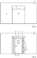
- a wall 1 is drawn in between a bare ceiling 2 and a bare floor 3 ( Fig. 1 ).
- the wall 1 is constructed in a sandwich construction with two cover layers 4 and a filling 5 arranged between them and can be composed of individual panels.
- Two holding profiles 6 are fastened to the unfinished ceiling 2 and the unfinished floor 3 by means of fastening means (not shown).
- the wall 1 or the individual panels are accommodated in the holding profiles 6.
- the holding profiles 6 have a number of bores 8, which are aligned with bores 9 in the cover layers 4 of the wall 1 or the individual panels.
- the wall 1 is held on the holding profiles 6 by means of rivets 7 (blind rivets) which run through the aligned bores 8, 9.
- the bores 9 of the cover layers 4 of the wall 1 can optionally be pre-drilled or can only be drilled into the cover layers 4 using the bores 8 of the holding profiles 6 as a mask after the wall 1 or the individual panels have been roughly aligned. It is also conceivable to drill the holes 8, 9 together.
- the wall 1 or the panels can additionally be secured to the holding profiles 6 by means of an adhesive 10.
- the adhesive 10 can also serve as a seal for the wall 1 with respect to the bare ceiling 2 and the bare floor 3.
- wall surfaces 11, 12 of wall 1 are referred to as inner wall surface 11 and as outer wall surface 12, this distinction being definable as required depending on the location of the viewer.
- the wall 1 has a wall opening 20 ( Fig. 2 ), which is a section of wall 1. End faces of the wall 1, which delimit the wall opening 20, are referred to as soffits 21. In the illustrated embodiment, three reveals 21 are provided, namely two vertical and one horizontal, ceiling-side. In variant embodiments, the wall cutout forming the wall opening can be designed such that a wall section remains as a threshold on the bottom side. In this case there would be a fourth, horizontal, soffit on the bottom.
- the soffits 21 can be formed by an open edge of the wall 1 (that is to say with the filling 5 exposed), by bent-over sections of the cover layers 4 or by an end profile or the like.
- the wall 1 has a mounting system 30 ( Fig. 3 ).
- the mounting system 30 has a frame support profile 31 which surrounds the reveal 21 and adjoining wall sections of the wall surface 11, 12 in a U-shape (see also Fig. 4 ), and an anchor plate 32 fastened to the frame support profile 31.
- a frame 33 is attached to the anchor plate 32.
- the frame 33 carries a door leaf 34 by means of hinges 35 and also creates a stop for the closed door leaf 34.
- the frame support profile 31 has a board-like end element 40, a first side element 41 and a second side element 42 ( Fig. 4 ).
- the end element 40 runs with one of its flat sides along the reveal 21 of the wall opening 20.
- the first side element 41 and the second side element 42 are connected to the end element 40 and project vertically from the latter in a web-like manner in a direction pointing away from the wall opening 20, so that they run along the wall surfaces 11, 12 of the wall 1.
- the first side element 41, the end element 40 and the second side element 42 encompass the reveal 21 and adjacent wall sections of the wall 1 in a U-shaped cross section.
- the side elements 41, 42 can be screwed to the end element 40 by means of profile connection screws 45 and can additionally or alternatively be glued to this.
- the end element 40 has two grooves 50, which fit together with folds 51 which are formed on the side elements 41, 42 on the wall side ( Fig. 5 ).
- the folds 51 engage in the grooves 50 and anchor the side elements 41, 42 with respect to the end element 40 against displacement in the lateral direction parallel to the reveal.
- a strip 52 is inserted in a flat groove 53 which is formed in the end element 40 on the side facing the wall opening 20 and is thus arranged between the end element 40 and the anchor plate 32.
- a plug 43 is arranged between the end element 40 and the reveal 21 of the wall 1 ( Fig. 4 ).
- An adhesive 44 can be arranged on the wall surfaces 11, 12 and on the reveal 21 in the area of the frame support profile 31.
- a wall fastening screw 46 extends from the side of the first side element 41 through the cover layer 4 of the inner wall surface 11 of the wall 1 and opens into the filling 5.
- a wall fastening screw 47 extends from the side of the second side element 42 through the cover layer 4 of the outer wall surface 12 of the wall 1, the filling 5 and the cover layer 4 of the inner wall surface 11 of the wall 1 and opens into the first side element 41.
- the adhesive 44 can give additional hold or only serve as an assembly aid. Furthermore, the adhesive 44 can serve as a seal and smoke barrier.
- the anchor plate 32 is screwed onto the end element 40 by means of plate connection screws 48.
- the frame 33 is fastened to the anchor plate 32 by suitable means, as will be explained in more detail later.
- a decorative wall covering 49 can be supported on the mounting system 30.
- the end element 40 can have a protrusion projecting laterally beyond the side elements 41, 42 in order to produce the wall spacing of the cladding 49 required for the interior.
- the elements 40, 41, 42 of the frame support profile 31 are made of wood or wood-based material.
- the anchor plate 32 is made of steel.
- the frame 33 is made of wood. The entire assembly system 30, as well as the frame 33, can be designed to be fire-resistant in accordance with fire resistance class B15 in order to meet the requirements for a fire protection wall.
- the screws 45-48 can be designed as wood screws (especially for solid wood) or chipboard screws (especially for wood-based materials) with countersunk heads.
- the wall fastening screws 46 and wall passage fastening screws 47 can, depending on the material of the cover layers 4 of the wall 1, also be designed as self-tapping screws or quick-assembly screws.
- the elements 40, 41, 42 are equipped with screw preparations for their appropriate, correct position and reliable use.
- the screws are to be screwed into the elements, in particular the profile connection screws 45 in the second and / or first side element 42, 41, the wall fastening screws 47 in the first side element 41 and / or the sheet metal fastening screws 48 in the end element 40, can be used if necessary
- Pre-bores in the form of blind or through holes may be provided, the diameter of which is adapted to the core diameter of the respective screws and the respective material.
- through bores are provided, the diameter of which is approximately the same or slightly larger than the nominal diameter of the respective screw.
- these through holes can also be adapted to the core diameter of the respective screws if screws are used which are only threaded in the area of the tip and in the shaft area over a length which corresponds to the thickness of the respective element 40, 41, 42, only have the core diameter.
- the frame support profile 31 has three elongated profile sections, two of which each run along one of the two vertical soffits 21 and one along the ceiling-side, horizontal soffit 21 of the wall opening 20.
- the frame 33 also has three elongated frame sections which are fastened to the respective profile sections of the frame support profile 31.
- a horizontally running profile section can also run on the bottom and possibly carry a frame section.
- an L-shaped profile 60 is first provided, which is formed by the end element 40 and the first side element 41 ( Figure 6A ).
- the front element 40 and the first side element 41 can only be inserted and / or screwed and / or glued.
- This L-shaped profile 60 is inserted into the wall opening 20 and aligned perpendicular and perpendicular.
- the L-shaped profile 60 is screwed to the wall 1 by means of the wall fastening screw 46.
- the adhesive 44 is applied beforehand. It should be noted that in this step all profile sections can already be assembled into a frame in accordance with the vertical and horizontal soffits to be supplied. The individual sections can also be attached individually.
- the second side element 42 is placed on the end element 40 and optionally fixed with adhesive 62 ( Figure 6C ). Then the second side element 42 and the end element 40 are screwed by means of the profile connecting screws 45 and then the second side element 42 is screwed to the wall 1 and the first side element 41 by means of the wall connecting screws 47.
- the frame 33 is positioned, aligned vertically and vertically and fastened to the end element 40 via the anchor plate 32 by means of the plate fastening screws 48 ( Figure 6D ). More precisely, the anchor plate 32 is first screwed to the frame 33 from the plate side by means of screws, not shown, and then the anchor plate 32 with the frame 33 fastened thereon is screwed onto the end element 40. If the anchor plate 32 is not provided continuously, but only as isolated plates (cf. for example Fig. 18 ), an assembly joint 63 that remains free in between is permanently sealed on both sides.
- the end element 40 has a protrusion projecting beyond the contour of the second side element 42, and the anchor plate 32 is arranged approximately centrally with respect to a lateral extent of the end element 40.
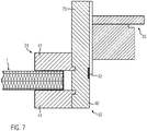
- the anchor plate 32 with the frame 33 at the end of the projection 70 ( Fig. 7 ) be moved.
- the frame 33 also comes closer to the edge of the mounting system 30, which may be desirable for aesthetic reasons.
- the projection 70 can also be provided on the side of the first side element 41 ( Fig. 8 ).
- the dimensioning and position of the projection 70 can be dependent on the desired wall distance of the cladding 49 (cf. Fig. 4 ) to get voted.
- the anchor plate 32 can have an L-shaped cross section with a long leg 81 and a short leg 82, so that the long leg 81 rests on the flat side of the end element 40 and the short leg 82 rests on the edge surface of the end element and can be screwed from there.
- the frame 33 can therefore be quasi flush with the lateral contour of the mounting system 33.
- the short leg 82 can be arranged recessed, so that overall a flush contour of second side element 42, short leg 82 of the anchor plate 32 and frame 33 can be achieved.
- the end element 40 can have a projection 70 on both sides, which allows even greater freedom in the mounting position of the anchor plate 32 and thus in the position of the frame 33 ( Fig. 9 ).
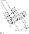
- the wall connecting screw 47 (cf. Fig. 4th , 6D ) be replaced by a further wall connecting screw 46 which only runs into the wall 1 but does not pass through it ( Fig. 10 ). Any squeezing of the wall 1 that could be caused by a clamping effect of the wall connecting screw 47 can thus be avoided.
- the frame 33 can have a groove seal 1000 as an abutment for the door leaf 34.
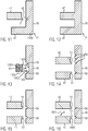
- the frame support profile 31 can have a one-piece L-profile 1100, which has the end element 40 and the first side element 41 as legs, and the second side element 42 as a separate element ( Fig. 11 ).
- the assembly of the end element 40 and the first side element 41 which was described in connection with the assembly method (cf. Figure 6A ), is then omitted.
- the frame support profile 31 can be formed in one piece overall ( Fig. 12 ).
- the vertical and horizontal profile sections cannot be connected to form a frame before assembly. This requires special measures in the design and layout. If the profile sections are mitered to each other, the installation joint 61 (cf. Figure 6A ) be dimensioned so that the profile sections can be inserted at an angle. At the same time, the overlap of the side elements 41, 42 over the wall surfaces 11, 12 must still be sufficient for the screw connection.
- profile corners can be provided, which are to be inserted at the corners of the wall opening and to which the profile sections then connect.
- the end element 40 has a further groove 1300, which is formed between the grooves 50 for receiving the folds 51 of the side elements 41, 42 ( Fig. 13 ).
- the further groove 1300 is designed to receive the plug 43 and for this purpose can have obliquely undercut flanks 1301 in order to clamp the flanks of the plug 43.
- the plug 43 is pressed into the groove 1300 in the insertion direction (arrow) 1302 before the mounting system 30 is mounted on the wall opening.
- the plug 43 can be designed as an elongated profile and can have a fold 1303 that matches the groove 1300.
- the fold 1303 can also be deburred.
- the ridged fold 1303 can have an end longitudinal slot 1304, so that the insertion end of the plug 43 can be compressed when it is inserted into the groove 1300.
- the end element 40 for the second side element 42 has not only one, but several, for example three, parallel grooves 50 which match the fold 51 of the second side element 42 ( Fig. 14 ).
- This enables adaptation to different wall thicknesses.
- only a single groove 50 is provided for the first side element 41.
- the modification with a plurality of grooves 50 is additionally or alternatively also possible for the first side element 41, which further increases the flexibility.
- the number of grooves is basically arbitrary.
- the grooves 50 of the end element 40 are undercut obliquely and the folds 51 of the side elements 41, 42 are trimmed to match ( Fig. 15 ).
- both side elements 41, 42 are to be pushed with their folds (ridges) 51 in the longitudinal direction into the grooves 50 of the end element 40 prior to assembly on the wall opening.
- a positive connection between the elements 40, 41, 42 is made without the need for additional connecting means.
- a quasi one-piece composite as in the in Fig. 12 Modification shown is produced, the same applies to that modification with regard to the assembly.
- the fold 51 of the first side element 41 has a burr and only the corresponding one of the grooves 50 of the end element 40 has an appropriately oblique undercut, and this shape is only provided on one side in this modification, namely on the side facing the wall ( Fig. 16 ).
- the fold 51 has a chamfer 1600 on the side facing away from it.
- the one-sided burr is sufficient to make handling especially in the Figure 6A shown step to facilitate and prevent the elements 40, 41 from falling apart when they are not glued.
- the chamfer 1600 facilitates the assembly of the elements 40, 41 by simply tilting the first side element 41 towards the end element 40 (arrow 1601 clockwise), inserting the deburred flank of the fold 51 into the groove 50 and into the undercut, and tilting the first Side element 41 (arrow 1601 in a counterclockwise direction) using the hooked-in burr as a hinge, as a result of which the flank of the fold 51 remote from the wall is pressed into the groove 50.
- the fold 51 of the second side element 42 and the corresponding groove 50 of the end element 40 are of a rectangular cross section in this modification.
- the second side element 42 can also have a fold 51 that is deburred on one side.
- the fold 51 can be formed on the side of the second side element 42 facing away from the wall, and the burr can also be formed on the side of the fold 51 facing away from the wall. If the L-profile 60 formed from the end element 40 and the first side element 41 (cf. Figure 6A ) is inserted into the wall opening 20, the second side element 42 with the fold 51 can then be inserted into the associated groove 50 in the same way as previously described for the first side element 41 and tilted in the direction of the wall 1 with the hooked-in burr as a hinge and be screwed there.
- the anchor plate 32 is not provided over the entire length of the frame, but can be realized by a number of individual plates which are arranged at discrete intervals ( Fig. 18 ). This can save material and weight.
- the side elements 41, 42 which protrude from the end element 40 in a web-like manner, lie on the cover sides 4 of the wall 1 over the entire or substantially the entire length of the frame support and provide with their multitude of screwing points (Wall connecting screws 46 and / or wall connecting screws 47) for continuous surface pressure ( Fig. 18 ).
- the anchor plate 32 can be dispensed with entirely and the frame 33 can be screwed directly onto the end element 40.
- this can also have a special aesthetic effect.
- Fire resistance class B15 is particularly widespread for maritime applications and, for example, in Resolution A.754 (18), adopted on November 4, 1993 (Agenda item 11), RECOMMENDATION ON FIRE RESISTANCE TESTS FOR "A”; "B” AND “F” CLASS DIVISIONS of the Assembly ofthe International Maritime Organization, especially chapter 9.1.2.
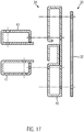
- the elements 40, 41, 42 of the mounting system 30 are made of wood or wood-based material. These materials are light, easy to machine and screwable. In further modifications, other materials with similar properties can also be used. For example, certain Plastics, composites, sintered materials or the like can be suitable materials. Under certain circumstances it is also possible to use bent sheet metal profiles, for example made of steel or other bendable metals, which roughly reproduce the cross-sectional contours of the elements 40, 41, 42 presented here or are at least designed to have the same effect ( Fig. 17 ). Alternatively, a continuously cast metal or plastic profile could be used.
- wall 1 Different concepts are known for the construction of wall 1.
- the following structure can be advantageous as a fire protection wall: on the outside, a support plate made of sheet metal or other incombustible plate material is arranged as a cover layer 4 on one or both sides.
- the filling 5 consists of mineral or rock wool, which is connected to the carrier plate.
- the filling 5 could also have a honeycomb structure made of metal or an impregnated cellulose material.
- the total thickness of the wall 1 can preferably be from about 25 mm.
- a 25 mm thick filling 5 made of stone wool can be framed by two cover layers 4 of 1 mm thickness made of sheet steel, so that the overall thickness of the wall 1 is 27 mm.
- a U-profile made of aluminum with a wall thickness of 1 mm can also be provided as reveal 21 (cf. Fig. 10 ).
- the elements 40, 41, 42 of the frame support profile 30 boards or strips made of wood or wood material of approximately 24 mm thickness can be used.
- the side elements 41, 42 can have a width of 50 mm (without folds 51), the end element 50 of 115 mm.
- the armature plate 32 made of steel can, for example, have a thickness of 4 mm.
- the oak frame 33 can have an overall thickness of 59 mm and an overall width of 70 mm.
- the dimensions and materials mentioned are chosen as an example of a usable embodiment of the invention. They do not limit the invention and can be changed as required.
- the assembly system 30 presented here can be used extremely flexibly since the end element 40 can be adjusted in width. It can also serve as a substructure for the decorative wall covering 49 and stabilize the comparatively light bulkhead partition 1.
- the mounting system 30 can be used for vehicles, in particular watercraft, as well as for buildings, such as drilling platforms, but also other vehicles and buildings with partitions, in particular fire protection walls.
- a door can also be a hatch or a window or other closure element in the sense of the application and the scope of protection of this invention.
Landscapes
- Engineering & Computer Science (AREA)
- Civil Engineering (AREA)
- Structural Engineering (AREA)
- Special Wing (AREA)
Applications Claiming Priority (1)
| Application Number | Priority Date | Filing Date | Title |
|---|---|---|---|
| DE102018121462.6A DE102018121462A1 (de) | 2018-09-03 | 2018-09-03 | Montagesystem für Wände |
Publications (1)
| Publication Number | Publication Date |
|---|---|
| EP3620603A1 true EP3620603A1 (fr) | 2020-03-11 |
Family
ID=67840992
Family Applications (1)
| Application Number | Title | Priority Date | Filing Date |
|---|---|---|---|
| EP19194928.8A Withdrawn EP3620603A1 (fr) | 2018-09-03 | 2019-09-02 | Système de montage pour murs |
Country Status (2)
| Country | Link |
|---|---|
| EP (1) | EP3620603A1 (fr) |
| DE (1) | DE102018121462A1 (fr) |
Families Citing this family (2)
| Publication number | Priority date | Publication date | Assignee | Title |
|---|---|---|---|---|
| CN113187151A (zh) * | 2021-05-10 | 2021-07-30 | 哈尔滨鸿盛建筑材料制造股份有限公司 | 框架填充墙板及墙体结构 |
| DE102023108824A1 (de) * | 2023-04-06 | 2024-10-10 | H & K Teckentrup GmbH & Co. KG | Zargen-Wandverbindungsanordnung |
Citations (5)
| Publication number | Priority date | Publication date | Assignee | Title |
|---|---|---|---|---|
| KR100485363B1 (ko) | 2002-11-22 | 2005-04-27 | (주)코스모 | 선박용 방화도어 |
| CN201419786Y (zh) | 2009-05-11 | 2010-03-10 | 江苏海陆装饰有限公司 | 船用围壁板检修门 |
| KR20120010772A (ko) | 2010-07-27 | 2012-02-06 | 삼성중공업 주식회사 | 선박 방화문의 시공구조 |
| DE202013012589U1 (de) * | 2013-01-10 | 2017-08-29 | Herport Innenausbauelemente Gmbh & Co. Kg | Vorrichtung zur Montage einer Türzarge |
| US20180148142A1 (en) | 2014-11-12 | 2018-05-31 | Imast S.C.A.R.L. | Fastening assembly of a fire door to a bulkhead |
Family Cites Families (2)
| Publication number | Priority date | Publication date | Assignee | Title |
|---|---|---|---|---|
| CH414121A (de) * | 1964-06-30 | 1966-05-31 | Systembau Ag | Türe |
| DE7423536U (de) * | 1974-07-11 | 1975-09-04 | Heer E | Futter für Mauerdurchgänge insbesondere Türfutter |
-
2018
- 2018-09-03 DE DE102018121462.6A patent/DE102018121462A1/de not_active Withdrawn
-
2019
- 2019-09-02 EP EP19194928.8A patent/EP3620603A1/fr not_active Withdrawn
Patent Citations (5)
| Publication number | Priority date | Publication date | Assignee | Title |
|---|---|---|---|---|
| KR100485363B1 (ko) | 2002-11-22 | 2005-04-27 | (주)코스모 | 선박용 방화도어 |
| CN201419786Y (zh) | 2009-05-11 | 2010-03-10 | 江苏海陆装饰有限公司 | 船用围壁板检修门 |
| KR20120010772A (ko) | 2010-07-27 | 2012-02-06 | 삼성중공업 주식회사 | 선박 방화문의 시공구조 |
| DE202013012589U1 (de) * | 2013-01-10 | 2017-08-29 | Herport Innenausbauelemente Gmbh & Co. Kg | Vorrichtung zur Montage einer Türzarge |
| US20180148142A1 (en) | 2014-11-12 | 2018-05-31 | Imast S.C.A.R.L. | Fastening assembly of a fire door to a bulkhead |
Non-Patent Citations (1)
| Title |
|---|
| RESOLUTION A., RECOMMENDATION ON FIRE RESISTANCE TESTS FOR „A''; B'' AND F'' CLASS DIVISIONS, vol. 754, no. 18, 4 November 1993 (1993-11-04) |
Also Published As
| Publication number | Publication date |
|---|---|
| DE102018121462A1 (de) | 2020-03-05 |
Similar Documents
| Publication | Publication Date | Title |
|---|---|---|
| EP3095944B1 (fr) | Section d'ouvrage comprenant un cadre de fenetre | |
| CH699782A2 (de) | Rahmenanschlussteil zur Befestigung an einem Rahmen. | |
| EP3060725B1 (fr) | Composite anti-effraction et structure de mur porteur, de toit ou de plafond | |
| AT10584U1 (de) | Stockrahmen und/oder flugelrahmen und verfahren zu seiner herstellung | |
| CH653873A5 (de) | Duschtrennwand. | |
| EP2946043B1 (fr) | Élément à profilés de construction | |
| DE102018121462A1 (de) | Montagesystem für Wände | |
| DE3502032A1 (de) | Tuer oder tor mit wenigstens einem isolierten fluegel, insbesondere brandschutztor | |
| DE3229262A1 (de) | Plattenfoermiges bauelement aus holz | |
| EP2357367A1 (fr) | Systèmes de montage pour plaques et tuyaux | |
| WO2008092699A1 (fr) | Dispositif d'inspection, en particulier élément de recouvrement d'inspection | |
| EP0918127B1 (fr) | Châssis de porte et dispositif de montage | |
| EP2820197B1 (fr) | Élément d'isolation | |
| AT527214B1 (de) | Platte für den Trockenausbau | |
| EP0078905A2 (fr) | Huisserie d'habillage pour le revêtement d'une ouverture dans une paroi pour une porte ou similaire | |
| EP2309068A2 (fr) | Elément en forme de bloc pour le support de charges sur des façades à système composites d'isolation thermique | |
| EP2644818A1 (fr) | Pièce de liaison | |
| DE4010920A1 (de) | Feuerschutztor | |
| DE4130086A1 (de) | Tuerblatt mit einem verstaerkungselement | |
| DE102017106922A1 (de) | Verleimkörper zum Verleimen einer Leichtbauplatte | |
| DE102016113023B4 (de) | Einbaurahmenelement und Wand mit abgedeckter Leibungsfläche | |
| DE19929664A1 (de) | Rahmenholm einer Glasrahmenkonstruktion für Brandschutzverglasungen | |
| EP1990477B1 (fr) | Panneau de construction léger doté d'une baguette de profilé | |
| AT412412B (de) | Adapterprofil | |
| EP1867796A2 (fr) | Panneaux composites pour les travaux de finition intérieure |
Legal Events
| Date | Code | Title | Description |
|---|---|---|---|
| PUAI | Public reference made under article 153(3) epc to a published international application that has entered the european phase |
Free format text: ORIGINAL CODE: 0009012 |
|
| STAA | Information on the status of an ep patent application or granted ep patent |
Free format text: STATUS: THE APPLICATION HAS BEEN PUBLISHED |
|
| AK | Designated contracting states |
Kind code of ref document: A1 Designated state(s): AL AT BE BG CH CY CZ DE DK EE ES FI FR GB GR HR HU IE IS IT LI LT LU LV MC MK MT NL NO PL PT RO RS SE SI SK SM TR |
|
| AX | Request for extension of the european patent |
Extension state: BA ME |
|
| STAA | Information on the status of an ep patent application or granted ep patent |
Free format text: STATUS: REQUEST FOR EXAMINATION WAS MADE |
|
| 17P | Request for examination filed |
Effective date: 20200911 |
|
| RBV | Designated contracting states (corrected) |
Designated state(s): AL AT BE BG CH CY CZ DE DK EE ES FI FR GB GR HR HU IE IS IT LI LT LU LV MC MK MT NL NO PL PT RO RS SE SI SK SM TR |
|
| STAA | Information on the status of an ep patent application or granted ep patent |
Free format text: STATUS: EXAMINATION IS IN PROGRESS |
|
| 17Q | First examination report despatched |
Effective date: 20221114 |
|
| STAA | Information on the status of an ep patent application or granted ep patent |
Free format text: STATUS: THE APPLICATION IS DEEMED TO BE WITHDRAWN |
|
| 18D | Application deemed to be withdrawn |
Effective date: 20230325 |