EP3620623A1 - Schaltbarer kipphebel und rollenhalter dafür - Google Patents
Schaltbarer kipphebel und rollenhalter dafür Download PDFInfo
- Publication number
- EP3620623A1 EP3620623A1 EP19195178.9A EP19195178A EP3620623A1 EP 3620623 A1 EP3620623 A1 EP 3620623A1 EP 19195178 A EP19195178 A EP 19195178A EP 3620623 A1 EP3620623 A1 EP 3620623A1
- Authority
- EP
- European Patent Office
- Prior art keywords
- roller
- arm
- lost motion
- wall
- inner arm
- Prior art date
- Legal status (The legal status is an assumption and is not a legal conclusion. Google has not performed a legal analysis and makes no representation as to the accuracy of the status listed.)
- Withdrawn
Links
- 238000002485 combustion reaction Methods 0.000 claims description 28
- 238000003466 welding Methods 0.000 description 6
- 230000009849 deactivation Effects 0.000 description 5
- 230000003247 decreasing effect Effects 0.000 description 2
- 239000000463 material Substances 0.000 description 2
- 230000004913 activation Effects 0.000 description 1
- 230000003466 anti-cipated effect Effects 0.000 description 1
- 238000005266 casting Methods 0.000 description 1
- 125000004122 cyclic group Chemical group 0.000 description 1
- 238000005242 forging Methods 0.000 description 1
- 239000000446 fuel Substances 0.000 description 1
- 238000003754 machining Methods 0.000 description 1
- 230000014759 maintenance of location Effects 0.000 description 1
- 230000007246 mechanism Effects 0.000 description 1
- 239000002184 metal Substances 0.000 description 1
- 238000004806 packaging method and process Methods 0.000 description 1
- 239000007787 solid Substances 0.000 description 1
- 238000013022 venting Methods 0.000 description 1
Images



Classifications
-
- F—MECHANICAL ENGINEERING; LIGHTING; HEATING; WEAPONS; BLASTING
- F01—MACHINES OR ENGINES IN GENERAL; ENGINE PLANTS IN GENERAL; STEAM ENGINES
- F01L—CYCLICALLY OPERATING VALVES FOR MACHINES OR ENGINES
- F01L1/00—Valve-gear or valve arrangements, e.g. lift-valve gear
- F01L1/12—Transmitting gear between valve drive and valve
- F01L1/18—Rocking arms or levers
- F01L1/181—Centre pivot rocking arms
-
- F—MECHANICAL ENGINEERING; LIGHTING; HEATING; WEAPONS; BLASTING
- F01—MACHINES OR ENGINES IN GENERAL; ENGINE PLANTS IN GENERAL; STEAM ENGINES
- F01L—CYCLICALLY OPERATING VALVES FOR MACHINES OR ENGINES
- F01L1/00—Valve-gear or valve arrangements, e.g. lift-valve gear
- F01L1/12—Transmitting gear between valve drive and valve
- F01L1/18—Rocking arms or levers
- F01L1/185—Overhead end-pivot rocking arms
-
- F—MECHANICAL ENGINEERING; LIGHTING; HEATING; WEAPONS; BLASTING
- F01—MACHINES OR ENGINES IN GENERAL; ENGINE PLANTS IN GENERAL; STEAM ENGINES
- F01L—CYCLICALLY OPERATING VALVES FOR MACHINES OR ENGINES
- F01L13/00—Modifications of valve-gear to facilitate reversing, braking, starting, changing compression ratio, or other specific operations
- F01L13/0005—Deactivating valves
-
- F—MECHANICAL ENGINEERING; LIGHTING; HEATING; WEAPONS; BLASTING
- F01—MACHINES OR ENGINES IN GENERAL; ENGINE PLANTS IN GENERAL; STEAM ENGINES
- F01L—CYCLICALLY OPERATING VALVES FOR MACHINES OR ENGINES
- F01L13/00—Modifications of valve-gear to facilitate reversing, braking, starting, changing compression ratio, or other specific operations
- F01L13/0015—Modifications of valve-gear to facilitate reversing, braking, starting, changing compression ratio, or other specific operations for optimising engine performances by modifying valve lift according to various working parameters, e.g. rotational speed, load, torque
-
- F—MECHANICAL ENGINEERING; LIGHTING; HEATING; WEAPONS; BLASTING
- F01—MACHINES OR ENGINES IN GENERAL; ENGINE PLANTS IN GENERAL; STEAM ENGINES
- F01L—CYCLICALLY OPERATING VALVES FOR MACHINES OR ENGINES
- F01L1/00—Valve-gear or valve arrangements, e.g. lift-valve gear
- F01L1/20—Adjusting or compensating clearance
- F01L1/22—Adjusting or compensating clearance automatically, e.g. mechanically
- F01L1/24—Adjusting or compensating clearance automatically, e.g. mechanically by fluid means, e.g. hydraulically
- F01L1/2405—Adjusting or compensating clearance automatically, e.g. mechanically by fluid means, e.g. hydraulically by means of a hydraulic adjusting device located between the cylinder head and rocker arm
-
- F—MECHANICAL ENGINEERING; LIGHTING; HEATING; WEAPONS; BLASTING
- F01—MACHINES OR ENGINES IN GENERAL; ENGINE PLANTS IN GENERAL; STEAM ENGINES
- F01L—CYCLICALLY OPERATING VALVES FOR MACHINES OR ENGINES
- F01L1/00—Valve-gear or valve arrangements, e.g. lift-valve gear
- F01L1/12—Transmitting gear between valve drive and valve
- F01L1/18—Rocking arms or levers
- F01L2001/186—Split rocking arms, e.g. rocker arms having two articulated parts and means for varying the relative position of these parts or for selectively connecting the parts to move in unison
-
- F—MECHANICAL ENGINEERING; LIGHTING; HEATING; WEAPONS; BLASTING
- F01—MACHINES OR ENGINES IN GENERAL; ENGINE PLANTS IN GENERAL; STEAM ENGINES
- F01L—CYCLICALLY OPERATING VALVES FOR MACHINES OR ENGINES
- F01L1/00—Valve-gear or valve arrangements, e.g. lift-valve gear
- F01L1/46—Component parts, details, or accessories, not provided for in preceding subgroups
- F01L2001/467—Lost motion springs
-
- F—MECHANICAL ENGINEERING; LIGHTING; HEATING; WEAPONS; BLASTING
- F01—MACHINES OR ENGINES IN GENERAL; ENGINE PLANTS IN GENERAL; STEAM ENGINES
- F01L—CYCLICALLY OPERATING VALVES FOR MACHINES OR ENGINES
- F01L2305/00—Valve arrangements comprising rollers
-
- F—MECHANICAL ENGINEERING; LIGHTING; HEATING; WEAPONS; BLASTING
- F01—MACHINES OR ENGINES IN GENERAL; ENGINE PLANTS IN GENERAL; STEAM ENGINES
- F01L—CYCLICALLY OPERATING VALVES FOR MACHINES OR ENGINES
- F01L2305/00—Valve arrangements comprising rollers
- F01L2305/02—Mounting of rollers
Definitions
- the present invention relates to a rocker arm for valve train of an internal combustion engine; more particularly to a rocker arm with an inner arm which selectively pivots relative to an outer arm, and even more particularly to such a rocker arm which includes first and second rollers supported by the inner arm and which includes roller retainers which retain the first and second rollers and which ground lost motion springs to the inner arm.
- Variable valve activation mechanisms for internal combustion engines are well known. It is known to lower the lift, or even to provide no lift at all, of one or more valves of an internal combustion engine, during periods of light engine load. Such valve deactivation or valve lift switching can substantially improve fuel efficiency of the internal combustion engine.
- a rocker arm acts between a rotating eccentric camshaft lobe and a pivot point on the internal combustion engine, such as a hydraulic lash adjuster, to open and close an engine valve.
- Switchable rocker arms may be a "deactivation" type or a "two-step” type.
- switchable deactivation rocker arm means the switchable rocker arm is capable of switching from a valve lift mode to a no lift mode.
- switchable two-step rocker arm means the switchable rocker arm is capable of switching from a first valve lift mode to a second valve lift mode, that is greater than no lift.
- the second valve lift mode may provide one or both of increased lift magnitude and increased lift duration or one or both of decreased lift magnitude and decreased lift duration of the engine valve compared to the first valve lift mode.
- switchable rocker arm when used herein, by itself, it includes both types.
- a typical switchable rocker arm includes an outer arm and an inner arm where the inner arm includes an inner arm follower which follows a first profile of a camshaft of the internal combustion engine and where the outer arm may include a pair of outer arm followers which follow respective second and third profiles of the camshaft.
- the follower of the inner arm and the followers of the outer arm may be either sliding surfaces or rollers and combinations thereof.
- the inner arm is movably connected to the outer arm and can be switched from a coupled state wherein the inner arm is immobilized relative to the outer arm, to a decoupled state wherein the inner arm can move relative to the outer arm.
- the outer arm of the switchable rocker arm is pivotally supported at a first end by the hydraulic lash adjuster which fits into a socket of the outer arm.
- a second end of the outer arm operates against an associated engine valve for opening and closing the valve by the rotation of an associated eccentric cam lobe acting on the follower of the inner arm.
- the inner arm is connected to the outer arm for pivotal movement about the outer arm's second end with the follower of the inner arm disposed between the first and second ends of the outer arm.
- Switching between the coupled state and the decoupled state is accomplished through a lock pin which is slidingly positioned in a lock pin bore of the outer arm. One end of the lock pin is moved into and out of engagement with the inner arm. Consequently, when the lock pin is engaged with the inner arm, the coupled state is achieved. Conversely, when the lock pin is not engaged with the inner arm, the decoupled state is achieved.
- a rocker arm for transmitting rotational motion from a camshaft to opening and closing motion of a combustion valve in an internal combustion engine includes an outer arm having a first wall and a second wall spaced apart from the second wall such that a central opening is provided between the first wall and the second wall; an inner arm which selectively pivots relative to the outer arm about a pivot shaft axis, the inner arm having a first side which faces toward the first wall and a second side which faces toward the second wall; a first lost motion spring having a first lost motion spring outer arm tang grounded to the outer arm and a first lost motion spring inner arm tang grounded to the inner arm, the first lost motion spring biasing the inner arm to pivot relative to the outer arm in a first direction about the pivot shaft axis; a second lost motion spring having a second lost motion spring outer arm tang grounded to the outer arm and a second lost motion spring inner arm tang grounded to the inner arm, the second lost motion spring biasing the inner arm to pivot relative to the outer arm
- the first roller retainer may include a first roller retainer aperture extending therethrough within which the roller shaft is located; and the second roller retainer may include a second roller retainer aperture extending therethrough within which the roller shaft is located.
- the first roller retainer surface may be convex as viewed in a direction of the roller shaft axis; and the second roller retainer surface is convex as viewed in the direction of the roller shaft axis.
- a plurality of first bearings may be provided radially between the roller shaft and the first roller such that the plurality of first bearings are captured axially between the first side of the inner arm and the first roller retainer; and a plurality of second bearings may be provided radially between the roller shaft and the second roller such that the plurality of first bearings are captured axially between the second side of the inner arm and the second roller retainer.
- the roller shaft may be captured axially along the roller shaft axis between the first lost motion spring inner arm tang and the second lost motion spring inner arm tang.
- the first lost motion spring inner arm tang may be captured axially along the roller shaft axis between the roller shaft and the first wall of the outer arm; and the second lost motion spring inner arm tang may be captured axially along the roller shaft axis between the roller shaft and the second wall of the outer arm.
- first lost motion spring inner arm tang may be captured axially along the roller shaft axis between the roller shaft and the first wall of the outer arm; and the second lost motion spring inner arm tang may be captured axially along the roller shaft axis between the roller shaft and the second wall of the outer arm.
- first roller retainer may include a first roller retainer projection which extends therefrom toward the first wall of the outer arm and upon which the first roller retainer surface is located; and the second roller retainer may include a second roller retainer projection which extends therefrom toward the second wall of the outer arm and upon which the second roller retainer surface is located.
- the rocker arm whereby: the first wall of the outer arm may include a first spring shaft aperture extending therethrough; the second wall of the outer arm may include a second spring shaft aperture extending therethrough; the first lost motion spring may include a plurality of coils, thereby defining a first lost motion spring aperture; the second lost motion spring may include a plurality of coils, thereby defining a second lost motion spring aperture; and the rocker arm may further comprise a spring shaft supported by the outer arm such that the spring shaft is located within the first spring shaft aperture and the second spring shaft aperture and such that the spring shaft passes through the first lost motion spring aperture and through the second lost motion spring aperture.
- the rocker arm whereby: the plurality of coils of the first lost motion spring may be located between the first wall and the second wall of the outer arm; and the plurality of coils of the second lost motion spring may be located between the first wall and the second wall of the outer arm.
- the rocker arm for transmitting rotational motion from a camshaft to opening and closing motion of a combustion valve in an internal combustion engine comprises:
- the rocker arms roller retainer may include a roller retainer aperture extending therethrough within which the roller shaft is located.
- the rocker arms roller retainer surface may be convex as viewed in a direction of the roller shaft axis.
- the rocker arms plurality of bearings may be provided radially between the roller shaft and the roller such that the plurality of bearings are captured axially between the inner arm and the roller retainer.
- the lost motion spring inner arm tang of the rocker arm may be captured axially along the roller shaft axis between the roller shaft and the first wall of the outer arm.
- the roller retainer of the rocker arm may include a roller retainer projection which extends therefrom toward the first wall of the outer arm and upon which the roller retainer surface is located.
- the rocker arm whereby: the first wall of the outer arm may include a first spring shaft aperture extending therethrough; the second wall of the outer arm may include a second spring shaft aperture extending therethrough; the lost motion spring may include a plurality of coils, thereby defining a lost motion spring aperture; and the rocker arm may further comprise a spring shaft supported by the outer arm such that the spring shaft is located within the first spring shaft aperture and the second spring shaft aperture and such that the spring shaft passes through the lost motion spring aperture.
- the plurality of coils of the lost motion spring may be located between the first wall and the second wall of the outer arm.
- the rocker arm for transmitting rotational motion from a camshaft to opening and closing motion of a combustion valve in an internal combustion engine may comprise:
- a rocker arm for transmitting rotational motion from a camshaft to opening and closing motion of a combustion valve in an internal combustion engine includes an outer arm having a first wall and a second wall spaced apart from the second; an inner arm which selectively pivots relative to the outer arm about a pivot shaft axis; a lost motion spring having a lost motion spring outer arm tang grounded to the outer arm and a lost motion spring inner arm tang grounded to the inner arm, the lost motion spring biasing the inner arm to pivot relative to the outer arm in a first direction about the pivot shaft axis; a lock pin which moves between 1) a coupled position in which the lock pin prevents the inner arm from pivoting about the pivot shaft axis relative to the outer arm past a predetermined position of the inner arm relative to the outer arm in a second direction which is opposite of the first direction and 2) a decoupled position in which the lock pin permits the inner arm to pivot relative to the outer arm past the predetermined position in the second direction about the pivot shaft
- a rocker arm for transmitting rotational motion from a camshaft to opening and closing motion of a combustion valve in an internal combustion engine includes an outer arm having a first wall and a second wall spaced apart from the second wall such that a central opening is provided between the first wall and the second wall, the first wall having a first spring shaft aperture extending therethrough and the second wall having a second spring shaft aperture extending therethrough; an inner arm which selectively pivots relative to the outer arm about a pivot shaft axis, the inner arm having a first side which faces toward the first wall and a second side which faces toward the second wall; a first lost motion spring having a plurality of coils, thereby defining a first lost motion spring aperture, the first lost motion spring also having a first lost motion spring outer arm tang grounded to the outer arm and a first lost motion spring inner arm tang grounded to the inner arm, the first lost motion spring biasing the inner arm to pivot relative to the outer arm in a first direction about the pivot shaft axi
- rocker arm described herein allows for compactness and ease of assembly as will be more readily apparent from a thorough reading of the following description.
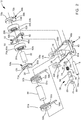
- rocker arm 10 in accordance with the invention is illustrated where rocker arm 10 is presented for illustrative purposes as a deactivation rocker arm but may alternatively be a two-step rocker arm, both of which may generically be referred to as a switchable rocker arm.
- Rocker arm 10 is included in valve train (not shown) of an internal combustion engine (not shown) in order to translate rotational motion of a camshaft 11 about a camshaft axis 11a to reciprocating motion of a combustion valve (not shown).
- camshaft 11 includes a base circle 11b which is centered about camshaft axis 11a and a lifting portion 11c which is eccentric to camshaft axis 11a. In this way, base circle 11b does not induce movement on the combustion valve while lifting portion 11c opens and closes the combustion valve.
- Rocker arm 10 includes an inner arm 12 that is pivotably disposed in a central opening 16 in an outer arm 14. Inner arm 12 selectively pivots within outer arm 14 on a pivot shaft 18 about a pivot shaft axis 18a such that pivot shaft 18 extends along, and is centered about, pivot shaft axis 18a.
- Inner arm 12 carries or supports a pair of followers illustrated as a first roller 20a and a second roller 20b carried by a roller shaft 22 that is supported by inner arm 12 such that first roller 20a, second roller 20b, and roller shaft 22 are each centered about, and extend along, a roller shaft axis 24.
- First roller 20a and second roller 20b are configured to follow base circle 11b and lifting portion 11c, to selectively impart lifting motion on a respective combustion valve.
- First roller 20a and second roller 20b are each cylindrical and tubular as shown.
- a plurality of first bearings 26a may rotatably support first roller 20a on roller shaft 22 for following base circle 11b and lifting portion 11c of camshaft 11 while a plurality of second bearings 26b may rotatably support second roller 20b on roller shaft 22 for following base circle 11b and lifting portion 11c of camshaft 11.
- First bearings 26a and second bearings 26b may be, for example, a plurality of rollers or needle bearings.
- Outer arm 14 includes a first wall 28a and a second wall 28b which are parallel to each other such that first wall 28a and second wall 28b are perpendicular to roller shaft axis 24 and such that first wall 28a and second wall 28b are spaced apart from each other in the direction of roller shaft axis 24 to define central opening 16 therebetween.
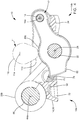
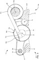
- a first lost motion spring 30a and a second lost motion spring 30b each act between inner arm 12 and outer arm 14 to pivot inner arm 12 away from outer arm 14 in a first direction, shown as clockwise as viewed in FIGS. 3 and 4 , about pivot shaft axis 18a.
- a socket 32 for pivotably mounting rocker arm 10 on a lash adjuster (not shown) is included at a first end 14a of outer arm 14 while a pad 34 for actuating a valve stem (not shown) is proximal to a second end 14b of outer arm 14.
- a latching arrangement 36 disposed within outer arm 14 proximal to first end 14a thereof selectively permits inner arm 12 to pivot relative to outer arm 14 about pivot shaft axis 18a and also selectively prevents inner arm 12 from pivoting relative to outer arm 14 about pivot shaft axis 18a in a second direction, illustrated as counterclockwise as viewed in FIGS. 3 and 4 , which is opposite of the first direction.
- outer arm 14 has been illustrated herein as not including followers which follow respective profiles of camshaft 11, it should be understood that outer arm 14 may include followers such as rollers as shown in United States Patent No. 7,305,951 or such as sliding surfaces as shown in United States Patent No. 7,882,814 to Spath et al. and United States Patent No. 6,668,779 to Hendriksma et al. , the disclosures of each of which are hereby incorporated by reference in their entirety.
- the followers of the outer arms are utilized to follow a profile of camshaft 11 which is a circle in the case of rocker arm 10 being a deactivation rocker arm and the followers of the outer arm are utilized to follow a profile of camshaft 11 which includes an eccentric portion similar to lifting portion 11c which provides a different magnitude or duration of lifting motion to rocker arm 10 in the case of rocker arm 10 being a two-step rocker arm.
- Outer arm 14 includes an outer arm body 38 at first end 14a and an outer arm bridge 40 at second end 14b.
- Outer arm body 38 joints first wall 28a and second wall 28b at first end 14a and also defines socket 32 therein.
- outer arm bridge 40 joins first wall 28a and second wall 28b at second end 14b and also defines pad 34 thereon.
- First wall 28a, second wall 28b, outer arm body 38, and outer arm bridge 40 may comprise a single piece of material which is formed, by way of non-limiting example, casting, forging, machining from solid, combinations thereof, and the like.
- first wall 28a Proximal to first end 14a, first wall 28a includes a first spring shaft aperture 42a extending therethrough and similarly, second wall 28b includes a second spring shaft aperture 42b extending therethrough, both of which receive a spring shaft 44 such that first spring shaft aperture 42a, second spring shaft aperture 42b, and spring shaft 44 are each centered about, and extend along, a spring shaft axis 44a.
- Spring shaft 44 interfaces with first spring shaft aperture 42a and second spring shaft aperture 42b in one of a close sliding interface and an interference fit which prevents radial movement of spring shaft 44 within first spring shaft aperture 42a and second spring shaft aperture 42b.
- Spring shaft 44 is fixed to outer arm 14, by way of non-limiting example only, with one or more of interference fit between spring shaft 44 and first spring shaft aperture 42a and second spring shaft aperture 42b, welding, and staking.
- first wall 28a Proximal to second end 14b, first wall 28a also includes a first pivot shaft aperture 46a extending therethrough and similarly, second wall 28b includes a second pivot shaft aperture 46b extending therethrough.
- First pivot shaft aperture 46a and second pivot shaft aperture 46b are each centered about, and extend along, pivot shaft axis 18a and each receive a portion of pivot shaft 18 therein in order to support pivot shaft 18 by outer arm 14.
- Pivot shaft 18 interfaces with first pivot shaft aperture 46a and second pivot shaft aperture 46b in a close sliding interface or an interference fit which prevents radial movement of pivot shaft 18 within first pivot shaft aperture 46a and second pivot shaft aperture 46b.
- Pivot shaft 18 is fixed to outer arm 14, by way of non-limiting example only, with one or more of interference fit between pivot shaft 18 and first pivot shaft aperture 46a and second pivot shaft aperture 46b, welding, and staking.
- Inner arm 12 may be planar as shown and includes an inner arm first side 48a which faces toward first wall 28a and also includes an inner arm second side 48b which is parallel to first side 48a and which faces toward second wall 28b.
- Inner arm 12 includes an inner arm roller shaft aperture 50 which extends therethrough from first side 48a to second side 48b such that inner arm roller shaft aperture 50 is centered about, and extends along, roller shaft axis 24.
- Roller shaft 22 extends through inner arm roller shaft aperture 50 such that roller shaft 22 and inner arm roller shaft aperture 50 are sized to interface in a close-slide fit or an interference fit such that roller shaft 22 is prevented from moving radially within inner arm roller shaft aperture 50.
- Roller shaft 22 extends from first side 48a toward first wall 28a of outer arm 14 and similarly, roller shaft 22 also extends from second side 48b toward second wall 28b of outer arm 14. Roller shaft 22 may be left unfixed within inner arm roller shaft aperture 50 in a close sliding fit, but, may alternatively be fixed to inner arm 12, by way of non-limiting example only, with one or more of interference fit between roller shaft 22 and inner arm roller shaft aperture 50 and welding.
- Inner arm 12 also includes an inner arm pivot shaft aperture 52 which extends therethrough from first side 48a to second side 48b such that inner arm pivot shaft aperture 52 is centered about, and extends along, pivot shaft axis 18a.
- Pivot shaft 18 extends through inner arm pivot shaft aperture 52 such that pivot shaft 18 and inner arm pivot shaft aperture 52 are sized to interface in a close-slide fit such that pivot shaft 18 is prevented from moving radially within inner arm pivot shaft aperture 52 while allowing inner arm 12 to pivot about pivot shaft 18.
- First lost motion spring 30a and second lost motion spring 30b are each coil torsion springs which are located between first wall 28a and second wall 28b.
- First lost motion spring 30a includes a plurality of coils, thereby defining a first lost motion spring aperture 54a through which spring shaft 44 passes.
- second lost motion spring 30b includes a plurality of coils, thereby defining a second lost motion spring aperture 54b through which spring shaft 44 passes. In this way, spring shaft 44 guides and retains first lost motion spring 30a and second lost motion spring 30b to outer arm 14 in use.
- First lost motion spring 30a includes a first lost motion spring outer arm tang 56a at one end thereof which is grounded to outer arm 14 at outer arm body 38 and also includes a first lost motion spring inner arm tang 58a at the other end thereof which is grounded to inner arm 12 as will be described in greater detail later.
- second lost motion spring 30b includes a second lost motion spring outer arm tang 56b at one end thereof which is grounded to outer arm 14 at outer arm body 38 and also includes a second lost motion spring inner arm tang 58b at the other end thereof which is grounded to inner arm 12 as will be described in greater detail later.
- First roller 20a and second roller 20b will now be described in greater detail.
- First roller 20a is cylindrical and hollow, thereby defining a first roller outer surface 60a which is cylindrical and centered about roller shaft axis 24 and also thereby defining a first roller inner surface 62a which is cylindrical and centered about roller shaft axis 24.
- First bearings 26a are located within, and ride upon, first roller inner surface 62a and the outer periphery of roller shaft 22, thereby rotatably supporting first roller 20a on roller shaft 22.
- second roller 20b is cylindrical and hollow, thereby defining a second roller outer surface 60b which is cylindrical and centered about roller shaft axis 24 and also thereby defining a second roller inner surface 62b which is cylindrical and centered about roller shaft axis 24.
- Second bearings 26b are located within, and ride upon, second roller inner surface 62b and the outer periphery of roller shaft 22, thereby rotatably supporting second roller 20b on roller shaft 22.
- a first roller retainer 64a is provided in order to retain first roller 20a and first bearings 26a and also in order to ground first lost motion spring inner arm tang 58a to inner arm 12 and similarly, a second roller retainer 64b is provided between second roller 20b and second wall 28b of outer arm 14 in order to retain second roller 20b and second bearings 26b and also in order to ground second lost motion spring inner arm tang 58b to inner arm 12.
- First roller retainer 64a includes a first roller retainer aperture 66a which extends therethrough such that first roller retainer aperture 66a is centered about, and extends along, roller shaft axis 24 and such that roller shaft 22 extends into first roller retainer aperture 66a.
- First roller retainer aperture 66a is sized to interface with roller shaft 22 in a close sliding fit such that radial movement of first roller retainer 64a relative to roller shaft 22 is prevented while allowing first roller retainer 64a to rotate freely about roller shaft axis 24 on roller shaft 22. In this way, first roller retainer 64a is carried by roller shaft 22. Alternatively, first roller retainer 64a may be fixed to roller shaft 22, for example, by interference fit or welding, thereby preventing first roller retainer 64a from rotating relative to roller shaft 22. First roller retainer 64a is annular in shape, thereby extending outward from first roller retainer aperture 66a to define a first roller retainer outer periphery 68a which surrounds roller shaft axis 24.
- First roller retainer outer periphery 68a is sized to cause first roller retainer 64a to be axially aligned, i.e. in the direction of roller shaft axis 24, with first bearings 26a and also to be axially aligned with first roller 20a, however, first roller retainer outer periphery 68a does not extend radially outward from roller shaft axis 24 to a greater extent than first roller outer surface 60a and second roller outer surface 60b. Consequently, first roller 20a and first bearings 26a are constrained axially between inner arm first side 48a and first roller retainer 64a.
- First roller retainer 64a includes a first roller retainer projection 70a extending axially, i.e.
- First roller retainer projection 70a includes a first roller retainer surface 72a which engages first lost motion spring inner arm tang 58a such that first lost motion spring inner arm tang 58a engages first roller retainer surface 72a to urge inner arm 12 to rotate about pivot shaft axis 18a in the first direction, i.e. clockwise as viewed in FIG. 5 .
- first lost motion spring inner arm tang 58a is grounded to inner arm 12 through roller shaft 22.
- first roller retainer surface 72a may preferably be convex as viewed in the direction of roller shaft axis 24, i.e. as viewed in FIG.
- first lost motion spring inner arm tang 58a may be convex at the interface with first roller retainer surface 72a.
- first roller retainer surface 72a may be concave if first lost motion spring inner arm tang 58a is convex at the interface with first roller retainer surface 72a. It is noted that first lost motion spring inner arm tang 58a is captured axially, i.e. in the direction of roller shaft axis 24, between first roller retainer 64a and first wall 28a of outer arm 14. Furthermore, first lost motion spring inner arm tang 58a is captured axially, i.e. in the direction of roller shaft axis 24, between roller shaft 22 and first wall 28a of outer arm 14.
- second roller retainer 64b includes a second roller retainer aperture 66b which extends therethrough such that second roller retainer aperture 66b is centered about, and extends along, roller shaft axis 24 and such that roller shaft 22 extends into second roller retainer aperture 66b.
- Second roller retainer aperture 66b is sized to interface with roller shaft 22 in a close sliding fit such that radial movement of second roller retainer 64b relative to roller shaft 22 is prevented while allowing second roller retainer 64b to rotate freely about roller shaft axis 24 on roller shaft 22. In this way, second roller retainer 64b is carried by roller shaft 22.
- second roller retainer 64b may be fixed to roller shaft 22, for example, by interference fit or welding, thereby preventing second roller retainer 64b from rotating relative to roller shaft 22.
- Second roller retainer 64b is annular in shape, thereby extending outward from second roller retainer aperture 66b to define a second roller retainer outer periphery 68b which surrounds roller shaft axis 24.
- Second roller retainer outer periphery 68b is sized to cause second roller retainer 64b to be axially aligned, i.e.
- Second roller retainer 64b includes a second roller retainer projection 70b extending axially, i.e. in the direction of roller shaft axis 24, toward second wall 28b.
- Second roller retainer projection 70b includes a second roller retainer surface 72b which engages second lost motion spring inner arm tang 58b such that second lost motion spring inner arm tang 58b engages second roller retainer surface 72b to urge inner arm 12 to rotate about pivot shaft axis 18a in the second direction, i.e. clockwise as viewed in FIGS. 3-5 and counterclockwise as viewed in FIG. 6 .
- second lost motion spring inner arm tang 58b is grounded to inner arm 12 through roller shaft 22.
- second roller retainer surface 72b may preferably be convex viewed in the direction of roller shaft axis 24, i.e. as viewed in FIG.
- second lost motion spring inner arm tang 58b may be convex at the interface with second roller retainer surface 72b.
- second roller retainer surface 72b may be concave if second lost motion spring inner arm tang 58b is convex at the interface with second roller retainer surface 72b. It is noted that second lost motion spring inner arm tang 58b is captured axially, i.e. in the direction of roller shaft axis 24, between second roller retainer 64b and second wall 28b of outer arm 14.
- second lost motion spring inner arm tang 58b is captured axially, i.e. in the direction of roller shaft axis 24, between roller shaft 22 and second wall 28b of outer arm 14, and consequently, roller shaft 22 is captured axially between first lost motion spring inner arm tang 58a and second lost motion spring inner arm tang 58b.
- Rocker arm 10 is selectively switched between a coupled state and a decoupled state by latching arrangement 36 which is actuated by application and venting of pressurized oil as will be described in greater detail later.
- latching arrangement 36 which is actuated by application and venting of pressurized oil as will be described in greater detail later.
- inner arm 12 is prevented from pivoting relative to outer arm 14 past a predetermined position of inner arm 12 relative to outer arm 14 in the second direction which is counterclockwise as viewed in FIG. 3 .
- inner arm 12, and therefore roller shaft 22 is coupled to outer arm 14, and rotation of lifting portion 11c is transferred from roller 20 through roller shaft 22 to pivotal movement of outer arm 14 about the lash adjuster which, in turn, reciprocates the associated valve.
- the decoupled state as shown in FIG.
- inner arm 12 is able to pivot relative to outer arm 14 past the predetermined position in the first direction.
- inner arm 12, and therefore roller shaft 22 is decoupled from outer arm 14.
- roller shaft 22 does not transfer rotation of the lifting cam to pivotal movement of outer arm 14, and the associated valve is not reciprocated.
- inner arm 12, together with first roller 20a, second roller 20b, and roller shaft 22 reciprocate within central opening 16, thereby compressing and uncompressing first lost motion spring 30a and second lost motion spring 30b in a cyclic manner such that first lost motion spring 30a and second lost motion spring 30b bias inner arm 12 to pivot relative to outer arm 14 in the first direction, shown as clockwise as viewed in FIG. 4 .
- Latching arrangement 36 includes a lock pin bore 74 which is centered about, and extends along, a lock pin bore axis 76 into outer arm body 38. As embodied herein, lock pin bore axis 76 may be parallel to pivot shaft axis 18a. Latching arrangement 36 also includes a lock pin 78 which is slidably disposed in lock pin bore 74. Lock pin 78 selectively engages inner arm 12 as shown in FIG. 3 , thereby preventing inner arm 12 from pivoting relative to outer arm 14 in the second direction past the predetermined position. Lock pin 78 also selectively disengages inner arm 12 as shown in FIG.
- Latching arrangement 36 also includes a lock pin spring 80 which urges lock pin 78 into engagement with inner arm 12 when desired, as shown in FIG. 3 , to achieve the coupled state.
- Lock pin spring 80 is positioned in a blind end of lock pin bore 74 and consequently is grounded to outer arm 14.
- an inner arm stop surface 82 of inner arm 12 is aligned with a lock pin stop surface 84 of lock pin 78, thereby preventing inner arm 12 from pivoting relative to outer arm 14 in the second direction past the predetermined position.
- Lock pin 78 is captured axially, i.e.
- Lock pin slot 90 is sufficiently large to allow the portion of inner arm 12 which includes inner arm stop surface 82 to pass therethrough.
- Oil may be supplied to pressure chamber 88 through a rocker arm oil passage 92 which extends from socket 32 to pressure chamber 88 where the pressure of oil supplied to pressure chamber 88 may be controlled, for example, by an oil control valve (not shown) which receives oil from an oil supply (not shown) of the internal combustion engine.
- latching arrangement 36 has been illustrated herein as defaulting to the coupled position in the absence of hydraulic pressure, it should now be understood that latching arrangement 36 may alternatively be configured to default to the decoupled position in the absence of hydraulic pressure. This may be accomplished, for example, by reversing the direction which lock pin spring 80 acts upon lock pin 78.
- latching arrangement 36 has been illustrated as being actuated based upon hydraulic pressure, other forms of actuation are anticipated, for example, by including a solenoid actuator which affects the position of lock pin 78 based on application of an electric current to the solenoid actuator.
- lock pin 46 has been described herein as being located within outer arm 14, it should be understood that lock pin 46 may alternatively be located within inner arm 12 and selectively engage a stop surface of outer arm 14.
- Rocker arm 10 as described herein allows for compactness, particularly in the direction of roller shaft axis 24, which is important for packaging within the internal combustion engine. This compactness is achieved, at least in part, by inner arm 12 which is planar, thereby allowing inner arm 12 to be simply made, for example by stamping the desired shape from sheet metal. Rocker arm 10 also allows for ease of assembly, particularly with respect to the assembly of first roller 20a, second roller 20b, roller shaft 22, first roller retainer 64a, and second roller retainer 64b to inner arm 12.
- each of these elements are captured between first lost motion spring inner arm tang 58a and second lost motion spring inner arm tang 58b and also between first wall 28a and second wall 28b such that these elements are axially constrained and maintained in an assembled relationship, thereby eliminating the need for additional retention which would require additional operations and/or materials.
Landscapes
- Engineering & Computer Science (AREA)
- Mechanical Engineering (AREA)
- General Engineering & Computer Science (AREA)
- Valve Device For Special Equipments (AREA)
Applications Claiming Priority (1)
| Application Number | Priority Date | Filing Date | Title |
|---|---|---|---|
| US16/123,421 US10544711B1 (en) | 2018-09-06 | 2018-09-06 | Switchable rocker arm and roller retainer thereof |
Publications (1)
| Publication Number | Publication Date |
|---|---|
| EP3620623A1 true EP3620623A1 (de) | 2020-03-11 |
Family
ID=67850948
Family Applications (1)
| Application Number | Title | Priority Date | Filing Date |
|---|---|---|---|
| EP19195178.9A Withdrawn EP3620623A1 (de) | 2018-09-06 | 2019-09-03 | Schaltbarer kipphebel und rollenhalter dafür |
Country Status (2)
| Country | Link |
|---|---|
| US (1) | US10544711B1 (de) |
| EP (1) | EP3620623A1 (de) |
Families Citing this family (1)
| Publication number | Priority date | Publication date | Assignee | Title |
|---|---|---|---|---|
| CN116529462A (zh) * | 2020-11-10 | 2023-08-01 | 伊顿智能动力有限公司 | 闩锁销组件和停用摇臂组件 |
Citations (6)
| Publication number | Priority date | Publication date | Assignee | Title |
|---|---|---|---|---|
| US6668779B2 (en) | 2002-05-08 | 2003-12-30 | Delphi Technologies, Inc. | Two-step finger follower rocker arm assembly |
| US7305951B2 (en) | 2005-05-09 | 2007-12-11 | Delphi Technologies, Inc. | Two-step roller finger follower |
| CN101086212A (zh) * | 2007-06-04 | 2007-12-12 | 奇瑞汽车有限公司 | 一种可控气缸停歇的发动机气门机构 |
| US7677213B2 (en) | 2005-08-04 | 2010-03-16 | Timken Us Llc | Deactivating roller finger follower |
| US7882814B2 (en) | 2008-03-03 | 2011-02-08 | Delphi Technologies, Inc. | Inner arm stop for a switchable rocker arm |
| US7926455B2 (en) | 2007-06-04 | 2011-04-19 | Schaeffler Kg | Roller finger follower for valve deactivation |
Family Cites Families (7)
| Publication number | Priority date | Publication date | Assignee | Title |
|---|---|---|---|---|
| JP2011208631A (ja) * | 2010-03-12 | 2011-10-20 | Nsk Ltd | タペットローラ軸受 |
| DE102010011828A1 (de) * | 2010-03-18 | 2011-09-22 | Schaeffler Technologies Gmbh & Co. Kg | Schaltbarer Hebel für einen Ventiltrieb einer Brennkraftmaschine |
| DE102010019064A1 (de) * | 2010-05-03 | 2011-11-03 | Schaeffler Technologies Gmbh & Co. Kg | Schaltbarer Hebel für einen Ventiltrieb einer Brennkraftmaschine |
| KR101461912B1 (ko) * | 2013-10-28 | 2014-11-14 | 현대자동차주식회사 | 밸브의 리프트 양을 가변시키는 가변밸브기구 |
| US10941680B2 (en) * | 2015-12-28 | 2021-03-09 | Eaton Corporation | Discrete variable valve lift engine systems and methods |
| JP6661478B2 (ja) * | 2016-06-02 | 2020-03-11 | 株式会社オティックス | 内燃機関の可変動弁機構 |
| WO2018038757A1 (en) * | 2016-08-23 | 2018-03-01 | Eaton Corporation | Two step rocker arm having side by side roller configuration |
-
2018
- 2018-09-06 US US16/123,421 patent/US10544711B1/en active Active
-
2019
- 2019-09-03 EP EP19195178.9A patent/EP3620623A1/de not_active Withdrawn
Patent Citations (6)
| Publication number | Priority date | Publication date | Assignee | Title |
|---|---|---|---|---|
| US6668779B2 (en) | 2002-05-08 | 2003-12-30 | Delphi Technologies, Inc. | Two-step finger follower rocker arm assembly |
| US7305951B2 (en) | 2005-05-09 | 2007-12-11 | Delphi Technologies, Inc. | Two-step roller finger follower |
| US7677213B2 (en) | 2005-08-04 | 2010-03-16 | Timken Us Llc | Deactivating roller finger follower |
| CN101086212A (zh) * | 2007-06-04 | 2007-12-12 | 奇瑞汽车有限公司 | 一种可控气缸停歇的发动机气门机构 |
| US7926455B2 (en) | 2007-06-04 | 2011-04-19 | Schaeffler Kg | Roller finger follower for valve deactivation |
| US7882814B2 (en) | 2008-03-03 | 2011-02-08 | Delphi Technologies, Inc. | Inner arm stop for a switchable rocker arm |
Also Published As
| Publication number | Publication date |
|---|---|
| US10544711B1 (en) | 2020-01-28 |
Similar Documents
| Publication | Publication Date | Title |
|---|---|---|
| EP3620624B1 (de) | Schaltbarer kipphebel und rollenhalter dafür | |
| EP1172528B1 (de) | Ventilsteuerungseinrichtung in einer Brennkraftmaschine | |
| US7546822B2 (en) | Switching finger follower assembly | |
| EP3363998B1 (de) | Schaltbarer kipphebel mit bewegungssperre | |
| US6691657B2 (en) | Two-step finger follower rocker arm | |
| US6615782B1 (en) | Two-step finger follower rocker arm | |
| US10605126B2 (en) | Switchable rocker arm | |
| US20180045081A1 (en) | Switching rocker arm assembly having eccentric axle for lash adjustment | |
| EP3527792B1 (de) | Schaltbarer kipphebel mit spielanpassung | |
| EP3620623A1 (de) | Schaltbarer kipphebel und rollenhalter dafür | |
| US10519817B1 (en) | Switchable rocker arm with lash adjustment and travel stop | |
| US10054014B1 (en) | Latching arrangement for switchable rocker arm | |
| US10900385B2 (en) | Switchable rocker arm | |
| US10704429B2 (en) | Switchable rocker arm | |
| US10465566B2 (en) | Switchable rocker arm with a travel stop | |
| US10871087B2 (en) | Switchable rocker arm | |
| US11828205B2 (en) | Latch assembly and compact rocker arm assembly | |
| US10677106B2 (en) | Rocker arm |
Legal Events
| Date | Code | Title | Description |
|---|---|---|---|
| PUAI | Public reference made under article 153(3) epc to a published international application that has entered the european phase |
Free format text: ORIGINAL CODE: 0009012 |
|
| STAA | Information on the status of an ep patent application or granted ep patent |
Free format text: STATUS: THE APPLICATION HAS BEEN PUBLISHED |
|
| AK | Designated contracting states |
Kind code of ref document: A1 Designated state(s): AL AT BE BG CH CY CZ DE DK EE ES FI FR GB GR HR HU IE IS IT LI LT LU LV MC MK MT NL NO PL PT RO RS SE SI SK SM TR |
|
| STAA | Information on the status of an ep patent application or granted ep patent |
Free format text: STATUS: REQUEST FOR EXAMINATION WAS MADE |
|
| 17P | Request for examination filed |
Effective date: 20200911 |
|
| RBV | Designated contracting states (corrected) |
Designated state(s): AL AT BE BG CH CY CZ DE DK EE ES FI FR GB GR HR HU IE IS IT LI LT LU LV MC MK MT NL NO PL PT RO RS SE SI SK SM TR |
|
| GRAP | Despatch of communication of intention to grant a patent |
Free format text: ORIGINAL CODE: EPIDOSNIGR1 |
|
| STAA | Information on the status of an ep patent application or granted ep patent |
Free format text: STATUS: GRANT OF PATENT IS INTENDED |
|
| INTG | Intention to grant announced |
Effective date: 20220622 |
|
| GRAS | Grant fee paid |
Free format text: ORIGINAL CODE: EPIDOSNIGR3 |
|
| STAA | Information on the status of an ep patent application or granted ep patent |
Free format text: STATUS: THE APPLICATION IS DEEMED TO BE WITHDRAWN |
|
| 18D | Application deemed to be withdrawn |
Effective date: 20221103 |