EP3620648A1 - Procédé de fourniture d'un joint à couteau pour pale de rotor complémentaire - Google Patents
Procédé de fourniture d'un joint à couteau pour pale de rotor complémentaire Download PDFInfo
- Publication number
- EP3620648A1 EP3620648A1 EP19189605.9A EP19189605A EP3620648A1 EP 3620648 A1 EP3620648 A1 EP 3620648A1 EP 19189605 A EP19189605 A EP 19189605A EP 3620648 A1 EP3620648 A1 EP 3620648A1
- Authority
- EP
- European Patent Office
- Prior art keywords
- add
- edge
- edge seal
- rotor blade
- width
- Prior art date
- Legal status (The legal status is an assumption and is not a legal conclusion. Google has not performed a legal analysis and makes no representation as to the accuracy of the status listed.)
- Withdrawn
Links
- 238000000034 method Methods 0.000 title claims abstract description 40
- 239000012812 sealant material Substances 0.000 claims abstract description 22
- 239000000565 sealant Substances 0.000 claims description 18
- 239000000945 filler Substances 0.000 claims description 15
- 239000000463 material Substances 0.000 claims description 10
- 238000007670 refining Methods 0.000 claims description 8
- 230000007704 transition Effects 0.000 claims description 5
- 230000001681 protective effect Effects 0.000 claims description 3
- 238000000151 deposition Methods 0.000 claims description 2
- 238000007789 sealing Methods 0.000 description 14
- 239000000853 adhesive Substances 0.000 description 10
- 230000001070 adhesive effect Effects 0.000 description 10
- 238000004519 manufacturing process Methods 0.000 description 9
- 239000010410 layer Substances 0.000 description 7
- 230000007423 decrease Effects 0.000 description 4
- 238000010586 diagram Methods 0.000 description 4
- 239000012790 adhesive layer Substances 0.000 description 3
- 239000003795 chemical substances by application Substances 0.000 description 3
- 239000007788 liquid Substances 0.000 description 3
- 230000009467 reduction Effects 0.000 description 3
- 230000007480 spreading Effects 0.000 description 3
- 238000003892 spreading Methods 0.000 description 3
- 238000004026 adhesive bonding Methods 0.000 description 2
- 230000002411 adverse Effects 0.000 description 2
- 230000006872 improvement Effects 0.000 description 2
- 229920001296 polysiloxane Polymers 0.000 description 2
- 239000003707 silyl modified polymer Substances 0.000 description 2
- 239000004593 Epoxy Substances 0.000 description 1
- 239000004831 Hot glue Substances 0.000 description 1
- VVQNEPGJFQJSBK-UHFFFAOYSA-N Methyl methacrylate Chemical compound COC(=O)C(C)=C VVQNEPGJFQJSBK-UHFFFAOYSA-N 0.000 description 1
- 208000004880 Polyuria Diseases 0.000 description 1
- 238000005299 abrasion Methods 0.000 description 1
- 239000011324 bead Substances 0.000 description 1
- 238000005452 bending Methods 0.000 description 1
- 230000008901 benefit Effects 0.000 description 1
- 230000015572 biosynthetic process Effects 0.000 description 1
- 238000001816 cooling Methods 0.000 description 1
- 230000007547 defect Effects 0.000 description 1
- 230000001419 dependent effect Effects 0.000 description 1
- 230000000694 effects Effects 0.000 description 1
- 230000003628 erosive effect Effects 0.000 description 1
- 239000012530 fluid Substances 0.000 description 1
- 238000009499 grossing Methods 0.000 description 1
- 230000000873 masking effect Effects 0.000 description 1
- 238000012986 modification Methods 0.000 description 1
- 230000004048 modification Effects 0.000 description 1
- 229920002635 polyurethane Polymers 0.000 description 1
- 239000004814 polyurethane Substances 0.000 description 1
- 230000008569 process Effects 0.000 description 1
- 230000001012 protector Effects 0.000 description 1
- 238000000518 rheometry Methods 0.000 description 1
- 238000007493 shaping process Methods 0.000 description 1
- 238000005507 spraying Methods 0.000 description 1
- 239000000126 substance Substances 0.000 description 1
Images
Classifications
-
- F—MECHANICAL ENGINEERING; LIGHTING; HEATING; WEAPONS; BLASTING
- F03—MACHINES OR ENGINES FOR LIQUIDS; WIND, SPRING, OR WEIGHT MOTORS; PRODUCING MECHANICAL POWER OR A REACTIVE PROPULSIVE THRUST, NOT OTHERWISE PROVIDED FOR
- F03D—WIND MOTORS
- F03D1/00—Wind motors with rotation axis substantially parallel to the air flow entering the rotor
- F03D1/06—Rotors
- F03D1/065—Rotors characterised by their construction elements
- F03D1/0675—Rotors characterised by their construction elements of the blades
-
- B—PERFORMING OPERATIONS; TRANSPORTING
- B29—WORKING OF PLASTICS; WORKING OF SUBSTANCES IN A PLASTIC STATE IN GENERAL
- B29C—SHAPING OR JOINING OF PLASTICS; SHAPING OF MATERIAL IN A PLASTIC STATE, NOT OTHERWISE PROVIDED FOR; AFTER-TREATMENT OF THE SHAPED PRODUCTS, e.g. REPAIRING
- B29C65/00—Joining or sealing of preformed parts, e.g. welding of plastics materials; Apparatus therefor
- B29C65/48—Joining or sealing of preformed parts, e.g. welding of plastics materials; Apparatus therefor using adhesives, i.e. using supplementary joining material; solvent bonding
- B29C65/52—Joining or sealing of preformed parts, e.g. welding of plastics materials; Apparatus therefor using adhesives, i.e. using supplementary joining material; solvent bonding characterised by the way of applying the adhesive
-
- B—PERFORMING OPERATIONS; TRANSPORTING
- B29—WORKING OF PLASTICS; WORKING OF SUBSTANCES IN A PLASTIC STATE IN GENERAL
- B29C—SHAPING OR JOINING OF PLASTICS; SHAPING OF MATERIAL IN A PLASTIC STATE, NOT OTHERWISE PROVIDED FOR; AFTER-TREATMENT OF THE SHAPED PRODUCTS, e.g. REPAIRING
- B29C66/00—General aspects of processes or apparatus for joining preformed parts
- B29C66/50—General aspects of joining tubular articles; General aspects of joining long products, i.e. bars or profiled elements; General aspects of joining single elements to tubular articles, hollow articles or bars; General aspects of joining several hollow-preforms to form hollow or tubular articles
- B29C66/51—Joining tubular articles, profiled elements or bars; Joining single elements to tubular articles, hollow articles or bars; Joining several hollow-preforms to form hollow or tubular articles
- B29C66/53—Joining single elements to tubular articles, hollow articles or bars
- B29C66/532—Joining single elements to the wall of tubular articles, hollow articles or bars
-
- B—PERFORMING OPERATIONS; TRANSPORTING
- B29—WORKING OF PLASTICS; WORKING OF SUBSTANCES IN A PLASTIC STATE IN GENERAL
- B29C—SHAPING OR JOINING OF PLASTICS; SHAPING OF MATERIAL IN A PLASTIC STATE, NOT OTHERWISE PROVIDED FOR; AFTER-TREATMENT OF THE SHAPED PRODUCTS, e.g. REPAIRING
- B29C73/00—Repairing of articles made from plastics or substances in a plastic state, e.g. of articles shaped or produced by using techniques covered by this subclass or subclass B29D
- B29C73/02—Repairing of articles made from plastics or substances in a plastic state, e.g. of articles shaped or produced by using techniques covered by this subclass or subclass B29D using liquid or paste-like material
-
- B—PERFORMING OPERATIONS; TRANSPORTING
- B29—WORKING OF PLASTICS; WORKING OF SUBSTANCES IN A PLASTIC STATE IN GENERAL
- B29C—SHAPING OR JOINING OF PLASTICS; SHAPING OF MATERIAL IN A PLASTIC STATE, NOT OTHERWISE PROVIDED FOR; AFTER-TREATMENT OF THE SHAPED PRODUCTS, e.g. REPAIRING
- B29C65/00—Joining or sealing of preformed parts, e.g. welding of plastics materials; Apparatus therefor
- B29C65/48—Joining or sealing of preformed parts, e.g. welding of plastics materials; Apparatus therefor using adhesives, i.e. using supplementary joining material; solvent bonding
- B29C65/4805—Joining or sealing of preformed parts, e.g. welding of plastics materials; Apparatus therefor using adhesives, i.e. using supplementary joining material; solvent bonding characterised by the type of adhesives
- B29C65/483—Reactive adhesives, e.g. chemically curing adhesives
-
- B—PERFORMING OPERATIONS; TRANSPORTING
- B29—WORKING OF PLASTICS; WORKING OF SUBSTANCES IN A PLASTIC STATE IN GENERAL
- B29L—INDEXING SCHEME ASSOCIATED WITH SUBCLASS B29C, RELATING TO PARTICULAR ARTICLES
- B29L2031/00—Other particular articles
- B29L2031/08—Blades for rotors, stators, fans, turbines or the like, e.g. screw propellers
- B29L2031/082—Blades, e.g. for helicopters
- B29L2031/085—Wind turbine blades
-
- F—MECHANICAL ENGINEERING; LIGHTING; HEATING; WEAPONS; BLASTING
- F05—INDEXING SCHEMES RELATING TO ENGINES OR PUMPS IN VARIOUS SUBCLASSES OF CLASSES F01-F04
- F05B—INDEXING SCHEME RELATING TO WIND, SPRING, WEIGHT, INERTIA OR LIKE MOTORS, TO MACHINES OR ENGINES FOR LIQUIDS COVERED BY SUBCLASSES F03B, F03D AND F03G
- F05B2230/00—Manufacture
- F05B2230/80—Repairing, retrofitting or upgrading methods
-
- F—MECHANICAL ENGINEERING; LIGHTING; HEATING; WEAPONS; BLASTING
- F05—INDEXING SCHEMES RELATING TO ENGINES OR PUMPS IN VARIOUS SUBCLASSES OF CLASSES F01-F04
- F05B—INDEXING SCHEME RELATING TO WIND, SPRING, WEIGHT, INERTIA OR LIKE MOTORS, TO MACHINES OR ENGINES FOR LIQUIDS COVERED BY SUBCLASSES F03B, F03D AND F03G
- F05B2240/00—Components
- F05B2240/20—Rotors
- F05B2240/30—Characteristics of rotor blades, i.e. of any element transforming dynamic fluid energy to or from rotational energy and being attached to a rotor
- F05B2240/306—Surface measures
- F05B2240/3062—Vortex generators
-
- F—MECHANICAL ENGINEERING; LIGHTING; HEATING; WEAPONS; BLASTING
- F05—INDEXING SCHEMES RELATING TO ENGINES OR PUMPS IN VARIOUS SUBCLASSES OF CLASSES F01-F04
- F05B—INDEXING SCHEME RELATING TO WIND, SPRING, WEIGHT, INERTIA OR LIKE MOTORS, TO MACHINES OR ENGINES FOR LIQUIDS COVERED BY SUBCLASSES F03B, F03D AND F03G
- F05B2240/00—Components
- F05B2240/57—Seals
-
- F—MECHANICAL ENGINEERING; LIGHTING; HEATING; WEAPONS; BLASTING
- F05—INDEXING SCHEMES RELATING TO ENGINES OR PUMPS IN VARIOUS SUBCLASSES OF CLASSES F01-F04
- F05B—INDEXING SCHEME RELATING TO WIND, SPRING, WEIGHT, INERTIA OR LIKE MOTORS, TO MACHINES OR ENGINES FOR LIQUIDS COVERED BY SUBCLASSES F03B, F03D AND F03G
- F05B2260/00—Function
- F05B2260/96—Preventing, counteracting or reducing vibration or noise
Definitions
- the invention describes a method of providing an edge seal for a rotor blade add-on.
- LEP leading edge protection
- VG vortex generator
- TE trailing edge
- a sharp step may be present at the edges of a panel or cover attached to the rotor blade. Such an abrupt height difference causes the air flow to transition from laminar to turbulent, which will adversely impact the annual energy production (AEP) of the wind turbine and may also contribute to wind turbine noise.
- AEP annual energy production
- Another way of reducing turbulence arising from a step along the edge of an add-on is to manufacture the add-on with a thin edge.
- mounting an add-on such as a LEP cover with a long thin edge may result in wrinkling along the edge, which contributes to non-conformance cost and reduces aerodynamic performance.
- an add-on such as an LEP shell may be manufactured to fit into a built-in recess on the blade surface.
- this approach is associated with strict requirements regarding production tolerances and quality, and significantly increases manufacturing costs while also being more prone to defects.
- the invention describes a method of providing an edge seal along a longitudinal edge of an add-on part mounted on the outer surface of a rotor blade.
- the inventive method comprises the steps of determining a height at the longitudinal edge of the add-on part; choosing a width for the edge seal to be applied onto the surface of the rotor blade, wherein the edge seal width is chosen to exceed the height at the longitudinal edge of the add-on part by a factor of at least twenty (i.e. the ratio of rotor blade edge seal width to add-on height is at least 20:1); and forming the edge seal by applying a sealant material at least in a volume defined by the height at the longitudinal edge of the add-on part and the determined blade surface edge seal width.
- edge seal width shall be understood to mean the width of the edge seal that is formed on the rotor blade surface, commencing along the longitudinal edge of the add-on part, and extending towards an outer seal edge that is generally parallel to the longitudinal edge of the add-on part.
- the longitudinal edge at the add-on part may be assumed to have the appearance of an abrupt step. There is no need to manufacture the add-on to have a progressively thinner longitudinal edge when it is to be mounted to a rotor blade using the inventive method, so that manufacture of such add-ons can be favourably economical. Since the add-on part is generally attached or bonded to the rotor blade in some way, for example by an adhesive bonding layer, the height at the longitudinal edge of the add-on part may be assumed to comprise the height of the add-on at that longitudinal edge, as well as the height of any adhesive layer for bonding the add-on to the rotor blade.
- the edge seal width may be understood to extend outward from the longitudinal edge of the add-on. Since the edge seal width is significantly larger than the add-on height, the improved edge seal favorably reduces or even eliminates AEP losses associated with the add-on.
- the edge seal obtained by the inventive method also significantly reduces noise generated by the rotor blade when turning, compared to a rotor blade not provided with such edge sealing along a part such as an LEP cover. This is primarily because the seal width obtained using the inventive method is significantly wider than any known type of edge seal.
- the inventive method may be used during manufacturing of a wind turbine rotor blade and also when repairing or upgrading an already installed rotor blade.
- the inventive method is equally applicable to existing blade add-ons, for which the contribution to AEP will improve when provided with the inventive edge sealing.
- the wind turbine rotor blade comprises at least one add-on part mounted to the outer surface of the rotor blade, and such an "extended" edge seal, as described above, formed along at least one longitudinal edge of the add-on part.
- additive may be understood to mean any of a protective cover, a plate or panel attached to the surface of the blade, especially along the longitudinal extension of the blade.
- edge sealing and “edge seal” may be used interchangeably.
- a sealing agent or an adhesive is used to form the edge seal along one or more edges of the add-on, either with or without an overlap as will be explained in the following.
- the terms "sealant material”, “edge sealer” and “sealing agent” may be used to refer to such an adhesive.
- the seal is formed using a liquid sealant that solidifies some time after application and which, when liquid, has a specific rheology that combines a desired sag resistance with a desired flowability.
- the solidified sealant is flexible, abrasion-resistant, and adheres well to the surface to which it is applied.
- the sealant may be a hot-melt adhesive that becomes firm upon cooling, for example.
- a sealant that becomes firm by a chemical curing process may be preferred.
- Exemplary materials may be epoxy, polyurethane, polyuria, silicone, silane modified polymers (SMP), methylmethacrylate (MMA), etc., chosen in view of the desired properties of sag resistance and flowability as indicated above.
- a sealant material may be chosen to have a specific adhesive viscosity offering a good balance between sag resistance and flowability, as well as a favorably high degree of flexibility in its cured state. The integrity of an edge seal formed along the longitudinal edges of an LEP using such a material will not suffer from repeated torsional bending of the rotor blade.
- the inventive method of aerodynamically optimizing the edges of an add-on is not limited to aerodynamic devices such as LEP covers.
- the add-on may be a plate comprising sensors, e.g. a flexible plate that conforms to the curved surface of the rotor blade.
- sensors e.g. a flexible plate that conforms to the curved surface of the rotor blade.
- the fixation of such a sensor plate to the rotor blade surface can benefit from the sealing concept of the present invention, achieving improvements in respect of AEP.
- Such a plate may be attached to the rotor blade surface at any position between the leading edge and trailing edge of the rotor blade, and may be mounted on the suction side or the pressure side of the rotor blade.
- an edge seal is formed along nay longitudinal edge of such a plate, using the inventive method.
- the edge step height of an add-on may be 0.7 mm.
- the edge step height of an add-on is the sum of the thickness at the outer edge of the add-on plus the thickness of any adhesive or bonding layer used to attach the add-on to the rotor blade.
- the minimum width of the edge sealing for this add-on is 14 mm.
- the minimum width of the edge sealing is 20 mm.
- the ratio of edge seal width to step height can vary between 20:1 to 100:1.
- the edge seal would be at least 10 mm wide, and up to 150 mm wide.
- Such relatively wide edge seals for rotor blade add-on parts have been observed (in wind tunnel tests) to result in an improved aerodynamic behavior.
- a further preferred embodiment of the invention is based on the insight that the laminar nature of the airflow over the rotor blade surface can be preserved by forming the edge seal over the longitudinal edge of the add-on, i.e. by having the edge seal "overlap" the outer surfaces of both the add-on and the rotor blade.
- the method comprises a step of determining an overlap width for the edge seal, in a region of the add-on surface next to its longitudinal edge.
- overlap width shall be understood to mean the width of the edge seal portion that extends onto the surface of the add-on. The overlap width is determined on the basis of the add-on height.
- the step of forming the edge seal then preferably comprises applying the sealant material also onto an overlap region of the add-on part.
- the overlap of the edge seal can advantageously form a smooth layer over the edge of the add-on.
- the edge seal width and overlap width for an edge seal are preferably "tuned" to a specific add-on in order to prevent or at least significantly delay the onset of flow transition from laminar to turbulent on the surface of the blade behind the edge of the add-on, i.e. downwind of the add-on.
- the extent (i.e. width) of the edge sealing and the extent of any overlap will be governed by the height of the edge step at the longitudinal edge of the add-on.
- the ratio of overlap width to step height can vary from 10:1 to 50:1.
- the overlap width would be 5 mm - 25 mm wide.
- the edge seal width would be 15 - 75 mm wide.
- the recommended ratios described above are significantly larger than typically used by solutions known in the art.
- the maximum possible width or extent of an edge sealing may also be determined or limited by a curvature of the rotor blade.
- the edge sealing proposed herein may be achieved by using a sealing agent or adhesive with sufficiently low viscosity, to be fluid enough to flow into any gaps and surface crevices formed during application of the add-on, and to ensure a smooth finish.
- the sealant material is preferably also chosen such that a smooth transition to the blade surface is assured.
- the sealant material may be applied using a tool set comprising a number of spatulas with different properties.
- the step of forming an edge seal comprises a step of depositing sealant material at least onto the surface of the rotor blade alongside the longitudinal edge of the add-on part. Then, a preliminary spatula is used to spread the sealant material in a region bounded by the longitudinal edge of the add-on part and the chosen edge seal width.
- the preliminary tool preferably has a flexibility and shape that facilitates the initial spreading of the sealant.
- a refining spatula is used to refine the shape of the sealant spread by the preliminary tool.
- the refining tool has a lower hardness than the preliminary tool.
- the inventive method can preferably include a step of delimiting the area of the intended edge seal using smooth, thin masking tape.
- One tape may extend along the outer edge of the intended edge seal, at a distance outward from the edge step. This distance is at least 20 times larger than the edge step height.
- the thickness of the tape is as small as possible, preferably at most 0.2 mm.
- the other boundary of the edge seal may be defined by the edge step.
- a second tape may be applied to the surface of the add-on, parallel to the longitudinal edge of the add-on. The sealant is then applied within these bounds.
- the sealant can initially be roughly deposited on the rotor blade (and add-on), for example in the form of a bead from a dispenser nozzle, or by spraying.
- the roughly applied sealant is then spread using a preliminary shaping tool, for example a flexible toothed spatula. This can be done by guiding the toothed spatula in the longitudinal direction of the rotor blade surface, between the edge seal bounds.
- a preliminary shaping tool for example a flexible toothed spatula. This can be done by guiding the toothed spatula in the longitudinal direction of the rotor blade surface, between the edge seal bounds.
- the tape or tapes are removed.
- the still-liquid sealant is then smoothed to its final shape by drawing a softer, flexible spatula over the spread sealant.
- This refining or smoothing step with the second tool serves to further decrease the height of the "wedge" of the edge seal between the edge step and the outer boundary of the edge seal.
- the second flexible spatula is
- a filler material may be used to augment the edge seal.
- filler material is applied along the edge of the add-on to reduce the edge step initially, i.e. to form a compact wedge or slope extending outward from the add-on edge.
- the sealant material is then applied over the filler.
- the filler material may have a higher viscosity than the sealant material to facilitate an easy build-up of the filler or bottom layer.
- the extent or width of the filler will be less than the blade surface edge seal width so that a uniform layer of sealant material can be applied over the filler to achieve a smooth transition to the rotor blade surface.
- the volume occupied by the filler material may be less than half the intended volume of the edge seal.
- the inventive edge seal reduces the negative impact of steps or other obstacles on the aerodynamic performance of a rotor blade.
- the inventive edge seal can ensure that an add-on is "AEP-neutral".
- the inventive method also makes it possible to implement add-ons such as LEP shells, LEP covers etc., with a higher edge thickness. This in turn is associated with cost reduction, since the formation of a thin edge is a cost-driving factor in the manufacture of add-ons such as LEP covers and shells.
- the edge sealing method described above contributes to the aerodynamic performance improvement of the LEP solution.
- the inventive edge sealing indirectly enables the use of a shell with a thicker edge, and thereby contributes to the reduction of manufacturing costs and can assist in avoiding penalties such as non-conformance costs.
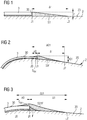
- Fig 1 shows an embodiment of the inventive edge seal S1 applied to an add-on 3, which can be any of a LEP cover, a shell, a TE cover, a VG panel, a TE panel, a sensor panel, etc.
- the add-on 3 is attached to the outer surface 20 of the rotor blade 2 by an adhesive bonding layer 33.
- the adhesive layer 33 may be regarded as an element of the add-on 3.
- the height t1 of the add-on 3 at its edge 3E is the sum of the thickness of the add-on 3 and the thickness of the adhesive layer 33.
- the add-on edge 3E may be assumed to run in a longitudinal direction of the rotor blade 2.
- the diagram clearly shows the "step" shape at the edge 3E of the add-on 3.
- an edge seal S1 is formed along the add-on edge 3E.
- the edge seal S1 commences at a first point J1 at the add-on edge 3E and extends to a second point J2, whereby the height of the seal S1 gradually decreases from a maximum at point J1 to a minimum at point J2.
- the ratio ⁇ 1:t1 is preferably at least 20:1.
- the volume of the edge seal S1 in this case is the cross-sectional area of the edge seal S1, i.e. (t1 x ⁇ 1)/2, multiplied by the length of the seal S1, e.g. the length of the longitudinal edge 3E of the add-on 3.
- Fig 2 shows a further embodiment of the inventive edge seal.
- the edge seal S01 is applied to a longitudinal edge 3E of an add-on 3, in this case an LEP cover mounted about the leading edge of a rotor blade 2.
- the edge seal S01 overlaps the longitudinal edge 3E of the add-on 3, i.e. the edge seal S01 commences at point J0 and extends to point J2.
- the total width ⁇ 01 of the edge seal S01 is therefore the width ⁇ 0 of the overlap S OV extending from point J0 to point J1, and the remaining edge seal width ⁇ 1 extending from point J1 to point J2.
- the height of the seal S01 gradually increases from a minimum at point J0 to a maximum at point J0, and gradually decreases from the maximum at point J1 to a minimum at point J2.
- the height of the seal S01 at its maximum may exceed the height of the add-on edge 3E by up to 2.0 mm, depending on the overlap width ⁇ 0 and/or on the edge seal width ⁇ 1 between point J1 and point J2. This height is based on the controlled layer thickness of the sealant or adhesive applied using a tool such as a spatula.
- Fig 3 shows a further embodiment of the inventive edge seal.
- the edge seal S01F in this case extends over a filler F that is first applied along the longitudinal add-on edge 3E.
- the filler F may be a quick-setting adhesive and/or a high-viscosity adhesive.
- the filler F can be applied to form a wedge with straight sides that are shorter than the height of the add-on 3.
- sealant material is applied over the cured or hardened filler F such that the resulting edge seal S01F overlaps the longitudinal edge 3E of the add-on 3, commencing at point J0 and extending to point J2.
- the total width ⁇ 01 of the edge seal S01F is measured from point J0 to point J2.
- the height of the seal S01F gradually increases from a minimum at point J0 to a maximum at point J0, and gradually decreases from the maximum at point J1 to a minimum at point J2.
- the filler F shown here could also be used in the embodiment of Fig 1 .
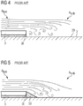
- Fig 4 shows an add-on 3 attached to a rotor blade surface 20 in a manner known from the prior art.
- the add-on 3 may be attached using an adhesive 33 as explained above.
- a longitudinal edge 3E of the add-on 3 forms an abrupt or distinct step, which can cause a laminar airflow A lam to break up, resulting in turbulence A turb downwind of the step 3E.
- Such turbulence A turb reduces the aerodynamic performance of the rotor blade 2, and accordingly lowers the AEP of the wind turbine.
- Fig 5 shows another prior art approach to securing an add-on 3 to a rotor blade surface 20.
- the step 3E formed by the longitudinal edge 3E of the add-on 3 is made less abrupt by a seal 50 applied along the edge 3E.
- the width of such a prior art edge seal 50 is generally only between 2 - 5 mm.
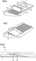
- Figs 6 and 7 show stages in forming an edge seal S01 using the inventive method.
- the sealant material S is roughly distributed along an edge 3E of the add-on 3, in this case a leading edge protector.
- a preliminary tool T0 the roughly applied sealant S is spread to fill a volume between the long edge 3E of the add-on 3 and a mask tape 60.
- the mask tape is preferably smooth with a thickness of at most 0.2 mm.
- the preliminary tool T0 is a flexible toothed spatula. Its flexibility is such that it can be bent in both axial directions to facilitate spreading of the sealant S.
- the still-soft sealant S is shaped as desired, in this case to form an overlap S OV alongside the long edge 3E of the add-on 3.
- the mask tape 60 can be removed after this step.
- the refining tool T1 is again used to further optimize the shape of the edge seal S01.
- This refining tool T1 is softer than the preliminary tool T0, for example with a Shore hardness of 40 - 60, so that it can be curved as desired during spreading of the sealant in order to achieve the desired edge seal profile shape.
- Fig 8 shows airflow over an add-on that has been given an edge seal S1 using the inventive method.
- the diagram shows that the laminar nature of the airflow A lam is maintained due to the smooth extended edge seal S1.
Landscapes
- Engineering & Computer Science (AREA)
- Mechanical Engineering (AREA)
- Life Sciences & Earth Sciences (AREA)
- Sustainable Development (AREA)
- Sustainable Energy (AREA)
- Chemical & Material Sciences (AREA)
- Combustion & Propulsion (AREA)
- General Engineering & Computer Science (AREA)
- Sealing Devices (AREA)
- Wind Motors (AREA)
- Lining Or Joining Of Plastics Or The Like (AREA)
- Turbine Rotor Nozzle Sealing (AREA)
Priority Applications (10)
| Application Number | Priority Date | Filing Date | Title |
|---|---|---|---|
| PCT/EP2019/072551 WO2020052939A1 (fr) | 2018-09-10 | 2019-08-23 | Procédé de fourniture d'un joint d'étanchéité de bord pour un complément de pale de rotor |
| AU2019338622A AU2019338622B2 (en) | 2018-09-10 | 2019-08-23 | Method of providing an edge seal for a rotor blade add-on |
| US17/264,965 US11454209B2 (en) | 2018-09-10 | 2019-08-23 | Method of providing an edge seal for a rotor blade add-on |
| CN201980059271.5A CN112639285A (zh) | 2018-09-10 | 2019-08-23 | 向转子叶片附加件提供边缘密封件的方法 |
| JP2021513184A JP7453962B2 (ja) | 2018-09-10 | 2019-08-23 | ロータブレード付属品用のエッジシールを提供する方法 |
| ES19769015T ES2986386T3 (es) | 2018-09-10 | 2019-08-23 | Método para proporcionar un sello de borde para un complemento de pala de rotor |
| PL19769015.9T PL3807524T3 (pl) | 2018-09-10 | 2019-08-23 | Sposób zapewnienia uszczelnienia krawędzi dla dodatku łopaty wirnika |
| DK19769015.9T DK3807524T3 (da) | 2018-09-10 | 2019-08-23 | Fremgangsmåde til tilvejebringelse af en kantforsegling til et tilføjet element til et rotorblad |
| FIEP19769015.9T FI3807524T3 (fi) | 2018-09-10 | 2019-08-23 | Menetelmä reunatiivisteen aikaansaamiseksi roottorin lavan lisävarusteelle |
| EP19769015.9A EP3807524B1 (fr) | 2018-09-10 | 2019-08-23 | Procédé de fourniture d'un joint d'étanchéité de bord pour un complément de pale de rotor |
Applications Claiming Priority (1)
| Application Number | Priority Date | Filing Date | Title |
|---|---|---|---|
| EP18193531 | 2018-09-10 |
Publications (1)
| Publication Number | Publication Date |
|---|---|
| EP3620648A1 true EP3620648A1 (fr) | 2020-03-11 |
Family
ID=67436797
Family Applications (2)
| Application Number | Title | Priority Date | Filing Date |
|---|---|---|---|
| EP19189605.9A Withdrawn EP3620648A1 (fr) | 2018-09-10 | 2019-08-01 | Procédé de fourniture d'un joint à couteau pour pale de rotor complémentaire |
| EP19769015.9A Active EP3807524B1 (fr) | 2018-09-10 | 2019-08-23 | Procédé de fourniture d'un joint d'étanchéité de bord pour un complément de pale de rotor |
Family Applications After (1)
| Application Number | Title | Priority Date | Filing Date |
|---|---|---|---|
| EP19769015.9A Active EP3807524B1 (fr) | 2018-09-10 | 2019-08-23 | Procédé de fourniture d'un joint d'étanchéité de bord pour un complément de pale de rotor |
Country Status (11)
| Country | Link |
|---|---|
| US (1) | US11454209B2 (fr) |
| EP (2) | EP3620648A1 (fr) |
| JP (1) | JP7453962B2 (fr) |
| CN (1) | CN112639285A (fr) |
| AU (1) | AU2019338622B2 (fr) |
| DK (1) | DK3807524T3 (fr) |
| ES (1) | ES2986386T3 (fr) |
| FI (1) | FI3807524T3 (fr) |
| PL (1) | PL3807524T3 (fr) |
| PT (1) | PT3807524T (fr) |
| WO (1) | WO2020052939A1 (fr) |
Cited By (3)
| Publication number | Priority date | Publication date | Assignee | Title |
|---|---|---|---|---|
| WO2020182763A1 (fr) * | 2019-03-08 | 2020-09-17 | Siemens Gamesa Renewable Energy A/S | Procédé de création d'une transition à partir d'un bord d'une pièce rapportée montée sur la surface externe d'une pale de rotor |
| WO2020182762A1 (fr) * | 2019-03-08 | 2020-09-17 | Siemens Gamesa Renewable Energy A/S | Procédé de mise en forme d'un joint d'étanchéité de bord pour pièce rapportée d'ailette de rotor |
| US12044202B2 (en) | 2021-10-21 | 2024-07-23 | Nordex Energy Se & Co. Kg | Wind turbine rotor blade and aerodynamic add-on element |
Families Citing this family (3)
| Publication number | Priority date | Publication date | Assignee | Title |
|---|---|---|---|---|
| DE102019134132A1 (de) * | 2019-12-12 | 2021-06-17 | Mankiewicz Gebr. & Co (Gmbh & Co Kg) | Vorrichtung und Verfahren zur Herstellung von Kantenschutzbeschichtungen |
| DE102022107681A1 (de) | 2022-03-31 | 2023-10-05 | Harting Ag | Zustandsüberwachungsvorrichtung, Rotorblatt und Windkraftanlage damit |
| US12655766B1 (en) * | 2025-04-03 | 2026-06-16 | Rtx Corporation | Fan inlet case strut |
Citations (5)
| Publication number | Priority date | Publication date | Assignee | Title |
|---|---|---|---|---|
| US4895491A (en) * | 1988-06-17 | 1990-01-23 | Environmental Elements Corp. | Fan blade protection system |
| DE102013210737A1 (de) * | 2013-06-10 | 2014-12-11 | Senvion Se | Befestigung von Vortexgeneratoren |
| US20170016426A1 (en) * | 2014-04-02 | 2017-01-19 | Wobben Properties Gmbh | Method for attaching a toothed rear edge to a blade rear edge of a rotor blade |
| EP3144525A1 (fr) * | 2015-09-16 | 2017-03-22 | Siemens Aktiengesellschaft | Pale de rotor de turbine éolienne et enveloppe de bord d'attaque épaisse |
| WO2018051153A1 (fr) * | 2016-09-13 | 2018-03-22 | Polytech A/S | Pale d'éolienne comprenant un couvercle de protection |
Family Cites Families (14)
| Publication number | Priority date | Publication date | Assignee | Title |
|---|---|---|---|---|
| US5375978A (en) * | 1992-05-01 | 1994-12-27 | General Electric Company | Foreign object damage resistant composite blade and manufacture |
| US5674337A (en) * | 1995-11-08 | 1997-10-07 | Align-Rite Tool Company | Decorative adhesive coving process for matching synthetic surfaces |
| US20100028160A1 (en) * | 2008-07-31 | 2010-02-04 | General Electric Company | Compressor blade leading edge shim and related method |
| US8425196B2 (en) * | 2011-01-28 | 2013-04-23 | General Electric Company | Wind turbine blades with a hardened substrate construction |
| DE102014106529B4 (de) * | 2014-05-09 | 2016-02-04 | Senvion Gmbh | Reparaturverfahren für Vortexgenerator und ein Bausatz dafür |
| ES2884114T3 (es) * | 2014-08-05 | 2021-12-10 | Lm Wp Patent Holding As | Pala de turbina eólica provista de dispositivo montado en la superficie |
| EP3533816B1 (fr) | 2014-11-10 | 2024-07-17 | Polytech A/S | Couvercle de protection préformé et pale d'éolienne |
| US9975137B2 (en) * | 2015-03-24 | 2018-05-22 | The Boeing Company | Systems and methods for sealant layering |
| US10060411B2 (en) * | 2015-07-22 | 2018-08-28 | General Electric Company | Rotor blade root assembly for a wind turbine |
| WO2018060297A1 (fr) | 2016-09-27 | 2018-04-05 | Siemens Aktiengesellschaft | Système de couverture pour protéger un bord d'attaque d'une pale de rotor d'éolienne |
| WO2018060298A1 (fr) | 2016-09-27 | 2018-04-05 | Siemens Aktiengesellschaft | Système d'enveloppe protectrice adhésive |
| EP3536947B1 (fr) | 2018-03-08 | 2023-07-12 | Siemens Gamesa Renewable Energy A/S | Couvercle de protection pour protéger un bord d'attaque d'une pale de turbine éolienne |
| EP3578806A1 (fr) | 2018-06-04 | 2019-12-11 | Siemens Gamesa Renewable Energy A/S | Procédé de réparation d'un bord d'attaque d'une pale de turbine éolienne |
| EP3633186A1 (fr) | 2018-10-01 | 2020-04-08 | Siemens Gamesa Renewable Energy A/S | Feuille adhésive pour le montage d'une enveloppe protectrice sur une pale d'éolienne et procédé de montage d'une enveloppe protectrice sur une pale d'éolienne |
-
2019
- 2019-08-01 EP EP19189605.9A patent/EP3620648A1/fr not_active Withdrawn
- 2019-08-23 PL PL19769015.9T patent/PL3807524T3/pl unknown
- 2019-08-23 CN CN201980059271.5A patent/CN112639285A/zh active Pending
- 2019-08-23 PT PT197690159T patent/PT3807524T/pt unknown
- 2019-08-23 EP EP19769015.9A patent/EP3807524B1/fr active Active
- 2019-08-23 ES ES19769015T patent/ES2986386T3/es active Active
- 2019-08-23 US US17/264,965 patent/US11454209B2/en active Active
- 2019-08-23 JP JP2021513184A patent/JP7453962B2/ja active Active
- 2019-08-23 AU AU2019338622A patent/AU2019338622B2/en active Active
- 2019-08-23 DK DK19769015.9T patent/DK3807524T3/da active
- 2019-08-23 WO PCT/EP2019/072551 patent/WO2020052939A1/fr not_active Ceased
- 2019-08-23 FI FIEP19769015.9T patent/FI3807524T3/fi active
Patent Citations (5)
| Publication number | Priority date | Publication date | Assignee | Title |
|---|---|---|---|---|
| US4895491A (en) * | 1988-06-17 | 1990-01-23 | Environmental Elements Corp. | Fan blade protection system |
| DE102013210737A1 (de) * | 2013-06-10 | 2014-12-11 | Senvion Se | Befestigung von Vortexgeneratoren |
| US20170016426A1 (en) * | 2014-04-02 | 2017-01-19 | Wobben Properties Gmbh | Method for attaching a toothed rear edge to a blade rear edge of a rotor blade |
| EP3144525A1 (fr) * | 2015-09-16 | 2017-03-22 | Siemens Aktiengesellschaft | Pale de rotor de turbine éolienne et enveloppe de bord d'attaque épaisse |
| WO2018051153A1 (fr) * | 2016-09-13 | 2018-03-22 | Polytech A/S | Pale d'éolienne comprenant un couvercle de protection |
Cited By (5)
| Publication number | Priority date | Publication date | Assignee | Title |
|---|---|---|---|---|
| WO2020182763A1 (fr) * | 2019-03-08 | 2020-09-17 | Siemens Gamesa Renewable Energy A/S | Procédé de création d'une transition à partir d'un bord d'une pièce rapportée montée sur la surface externe d'une pale de rotor |
| WO2020182762A1 (fr) * | 2019-03-08 | 2020-09-17 | Siemens Gamesa Renewable Energy A/S | Procédé de mise en forme d'un joint d'étanchéité de bord pour pièce rapportée d'ailette de rotor |
| US11939947B2 (en) | 2019-03-08 | 2024-03-26 | Siemens Gamesa Renewable Energy A/S | Method of shaping an edge seal for a rotor blade add-on |
| US12180924B2 (en) | 2019-03-08 | 2024-12-31 | Siemens Gamesa Renewable Energy A/S | Method for creating a transition from an edge of an add-on part mounted on the outer surface of a rotor blade |
| US12044202B2 (en) | 2021-10-21 | 2024-07-23 | Nordex Energy Se & Co. Kg | Wind turbine rotor blade and aerodynamic add-on element |
Also Published As
| Publication number | Publication date |
|---|---|
| PL3807524T3 (pl) | 2024-09-02 |
| EP3807524A1 (fr) | 2021-04-21 |
| FI3807524T3 (fi) | 2024-07-31 |
| US11454209B2 (en) | 2022-09-27 |
| DK3807524T3 (da) | 2024-07-22 |
| AU2019338622A1 (en) | 2021-02-18 |
| EP3807524B1 (fr) | 2024-05-29 |
| US20210324829A1 (en) | 2021-10-21 |
| CN112639285A (zh) | 2021-04-09 |
| JP7453962B2 (ja) | 2024-03-21 |
| WO2020052939A1 (fr) | 2020-03-19 |
| JP2022503667A (ja) | 2022-01-12 |
| ES2986386T3 (es) | 2024-11-11 |
| AU2019338622B2 (en) | 2022-03-10 |
| PT3807524T (pt) | 2024-08-06 |
Similar Documents
| Publication | Publication Date | Title |
|---|---|---|
| EP3807524B1 (fr) | Procédé de fourniture d'un joint d'étanchéité de bord pour un complément de pale de rotor | |
| US11939947B2 (en) | Method of shaping an edge seal for a rotor blade add-on | |
| CN103266985A (zh) | 后缘带 | |
| DK178435B1 (en) | Wind turbine blades with a hardened substrate construction | |
| EP3380720B1 (fr) | Pale d'éolienne avec dispositif aérodynamique attaché à cela | |
| US12180924B2 (en) | Method for creating a transition from an edge of an add-on part mounted on the outer surface of a rotor blade | |
| CN109790816A (zh) | 包括保护罩的风力涡轮机叶片 | |
| US20200166015A1 (en) | A method of coating a rotor blade for a wind turbine | |
| EP3504428A1 (fr) | Système de couverture pour protéger un bord d'attaque d'une pale de rotor d'éolienne | |
| CN116498485A (zh) | 风能设备转子叶片和降低其噪音排放的方法 | |
| WO2017088881A1 (fr) | Pale d'éolienne sur laquelle est fixé un dispositif aérodynamique | |
| BR112021016849B1 (pt) | Método de criação de uma transição a partir de uma borda de uma parte de adição montada na superfície externa de uma lâmina de rotor e lâmina de rotor | |
| PL230525B1 (pl) | Lopata turbiny wiatrowej | |
| BR112021017130B1 (pt) | Método de moldar uma vedação de borda para um complemento de pá de rotor e pá de rotor de turbina eólica |
Legal Events
| Date | Code | Title | Description |
|---|---|---|---|
| PUAI | Public reference made under article 153(3) epc to a published international application that has entered the european phase |
Free format text: ORIGINAL CODE: 0009012 |
|
| AK | Designated contracting states |
Kind code of ref document: A1 Designated state(s): AL AT BE BG CH CY CZ DE DK EE ES FI FR GB GR HR HU IE IS IT LI LT LU LV MC MK MT NL NO PL PT RO RS SE SI SK SM TR |
|
| STAA | Information on the status of an ep patent application or granted ep patent |
Free format text: STATUS: THE APPLICATION IS DEEMED TO BE WITHDRAWN |
|
| 18D | Application deemed to be withdrawn |
Effective date: 20200912 |