EP3620649A1 - Commande d'éoliennes en présence de sillage - Google Patents
Commande d'éoliennes en présence de sillage Download PDFInfo
- Publication number
- EP3620649A1 EP3620649A1 EP18193507.3A EP18193507A EP3620649A1 EP 3620649 A1 EP3620649 A1 EP 3620649A1 EP 18193507 A EP18193507 A EP 18193507A EP 3620649 A1 EP3620649 A1 EP 3620649A1
- Authority
- EP
- European Patent Office
- Prior art keywords
- wind
- wind turbine
- yaw
- angle
- rotor
- Prior art date
- Legal status (The legal status is an assumption and is not a legal conclusion. Google has not performed a legal analysis and makes no representation as to the accuracy of the status listed.)
- Withdrawn
Links
Images


Classifications
-
- F—MECHANICAL ENGINEERING; LIGHTING; HEATING; WEAPONS; BLASTING
- F03—MACHINES OR ENGINES FOR LIQUIDS; WIND, SPRING, OR WEIGHT MOTORS; PRODUCING MECHANICAL POWER OR A REACTIVE PROPULSIVE THRUST, NOT OTHERWISE PROVIDED FOR
- F03D—WIND MOTORS
- F03D7/00—Controlling wind motors
- F03D7/02—Controlling wind motors the wind motors having rotation axis substantially parallel to the air flow entering the rotor
- F03D7/0204—Controlling wind motors the wind motors having rotation axis substantially parallel to the air flow entering the rotor for orientation in relation to wind direction
-
- F—MECHANICAL ENGINEERING; LIGHTING; HEATING; WEAPONS; BLASTING
- F03—MACHINES OR ENGINES FOR LIQUIDS; WIND, SPRING, OR WEIGHT MOTORS; PRODUCING MECHANICAL POWER OR A REACTIVE PROPULSIVE THRUST, NOT OTHERWISE PROVIDED FOR
- F03D—WIND MOTORS
- F03D7/00—Controlling wind motors
- F03D7/02—Controlling wind motors the wind motors having rotation axis substantially parallel to the air flow entering the rotor
- F03D7/04—Automatic control; Regulation
- F03D7/042—Automatic control; Regulation by means of an electrical or electronic controller
- F03D7/048—Automatic control; Regulation by means of an electrical or electronic controller controlling wind farms
-
- F—MECHANICAL ENGINEERING; LIGHTING; HEATING; WEAPONS; BLASTING
- F05—INDEXING SCHEMES RELATING TO ENGINES OR PUMPS IN VARIOUS SUBCLASSES OF CLASSES F01-F04
- F05B—INDEXING SCHEME RELATING TO WIND, SPRING, WEIGHT, INERTIA OR LIKE MOTORS, TO MACHINES OR ENGINES FOR LIQUIDS COVERED BY SUBCLASSES F03B, F03D AND F03G
- F05B2270/00—Control
- F05B2270/10—Purpose of the control system
- F05B2270/20—Purpose of the control system to optimise the performance of a machine
- F05B2270/204—Purpose of the control system to optimise the performance of a machine taking into account the wake effect
-
- F—MECHANICAL ENGINEERING; LIGHTING; HEATING; WEAPONS; BLASTING
- F05—INDEXING SCHEMES RELATING TO ENGINES OR PUMPS IN VARIOUS SUBCLASSES OF CLASSES F01-F04
- F05B—INDEXING SCHEME RELATING TO WIND, SPRING, WEIGHT, INERTIA OR LIKE MOTORS, TO MACHINES OR ENGINES FOR LIQUIDS COVERED BY SUBCLASSES F03B, F03D AND F03G
- F05B2270/00—Control
- F05B2270/30—Control parameters, e.g. input parameters
- F05B2270/32—Wind speeds
-
- F—MECHANICAL ENGINEERING; LIGHTING; HEATING; WEAPONS; BLASTING
- F05—INDEXING SCHEMES RELATING TO ENGINES OR PUMPS IN VARIOUS SUBCLASSES OF CLASSES F01-F04
- F05B—INDEXING SCHEME RELATING TO WIND, SPRING, WEIGHT, INERTIA OR LIKE MOTORS, TO MACHINES OR ENGINES FOR LIQUIDS COVERED BY SUBCLASSES F03B, F03D AND F03G
- F05B2270/00—Control
- F05B2270/30—Control parameters, e.g. input parameters
- F05B2270/321—Wind directions
-
- F—MECHANICAL ENGINEERING; LIGHTING; HEATING; WEAPONS; BLASTING
- F05—INDEXING SCHEMES RELATING TO ENGINES OR PUMPS IN VARIOUS SUBCLASSES OF CLASSES F01-F04
- F05B—INDEXING SCHEME RELATING TO WIND, SPRING, WEIGHT, INERTIA OR LIKE MOTORS, TO MACHINES OR ENGINES FOR LIQUIDS COVERED BY SUBCLASSES F03B, F03D AND F03G
- F05B2270/00—Control
- F05B2270/30—Control parameters, e.g. input parameters
- F05B2270/329—Azimuth or yaw angle
-
- Y—GENERAL TAGGING OF NEW TECHNOLOGICAL DEVELOPMENTS; GENERAL TAGGING OF CROSS-SECTIONAL TECHNOLOGIES SPANNING OVER SEVERAL SECTIONS OF THE IPC; TECHNICAL SUBJECTS COVERED BY FORMER USPC CROSS-REFERENCE ART COLLECTIONS [XRACs] AND DIGESTS
- Y02—TECHNOLOGIES OR APPLICATIONS FOR MITIGATION OR ADAPTATION AGAINST CLIMATE CHANGE
- Y02E—REDUCTION OF GREENHOUSE GAS [GHG] EMISSIONS, RELATED TO ENERGY GENERATION, TRANSMISSION OR DISTRIBUTION
- Y02E10/00—Energy generation through renewable energy sources
- Y02E10/70—Wind energy
- Y02E10/72—Wind turbines with rotation axis in wind direction
Definitions
- the present invention relates to a method and to a wind park controller for controlling at least one wind turbine in a wind park comprising plural wind turbines and relates further to a wind park comprising the wind park controller.
- a wind park comprises a plurality of wind turbines. Some wind turbines are located downstream of other wind turbines, depending on a current wind direction. The upstream wind turbines may reduce the wind speed and wind energy experienced by the downstream wind turbines. At the downstream wind turbines also a turbulence of the wind may increase. A wind shadow region downstream or behind an upstream wind turbine may also be referred to as a wake region, or simply wake, of that upstream wind turbine.
- optimised blade pitch, rotor speed, power production set-points, rotor tilt and/or yaw offsets or other control settings on the wind turbines can be used.
- the upstream wind turbine may adapt its control settings to reduce wake-induced loads or to optimise total production of the wind farm.
- optimised settings are most commonly based on wind farm models that assume knowledge of the wind conditions coming into the wind farm and the layout of the wind farm.
- the optimisation settings are based on the situations when all wind turbines are in operation.
- upstream turbines will be identified that may have an impact on other downstream wind turbines and the respective upstream turbines are controlled.
- One control action may be setting the yaw angle of the upstream wind turbine.
- yaw misalignment angle is used to refer to a current yaw state of the wind turbine, wherein such an angle is defined as an angle between a rotating axis of a rotation shaft of the wind turbine and a current wind direction upstream of that wind turbine.
- yaw offset or "yaw offset setpoint” is used to refer to a control setting which should be met by the yaw misalignment angle when a control action is performed.
- positive yaw angles will be used in the document for angles defining a clockwise diversion of the turbine rotor axis from the main wind direction as seen from above the turbine.
- Negative yaw angles will be used in the document for angles defining a counterclockwise diversion of the turbine rotor axis from the main wind direction as seen from above the turbine. Absolute values of these positive and negative yaw angles increase when the rotor orientation departs further from an alignment of the turbine rotor axis and the main wind direction, wherein a perfect alignment of the turbine rotor axis and the main wind direction is represented by yaw angle of 0 degree.
- the method which will later be discussed in this document however also allows for alternative definitions where counterclockwise rotation is regarded positive yaw angle and clockwise rotation is regarded negative yaw angle.
- an upstream turbine may have a specific yaw angle setting and a change of wind condition may result in a control action such that the yaw position is drastically changed, e.g. a repositioning from a higher value positive yaw angle to a higher value negative yaw angle.
- a repositioning from a higher value positive yaw angle to a higher value negative yaw angle e.g. a repositioning from a higher value positive yaw angle to a higher value negative yaw angle.
- this also may trigger challenges as the repositioning of the rotor may take some time and wind conditions may change faster than the repositioning takes place.
- several of these major repositionings of the rotor yaw angle may happen in a fairly short time interval.
- the present invention seeks to address these problems and mitigate related drawbacks.
- a method for controlling a first wind turbine of a plurality of wind turbines of a wind park wherein a second wind turbine of the plurality of wind turbines can be affected by a wake region caused by the first wind turbine which is positioned upstream of the second wind turbine, wherein a rotor yaw offset angle set point for the first wind turbine is defined to follow a hysteresis characteristic.
- a switch from a range of positive yaw offset angles to negative yaw offset angles may be prevented if shortly before a switch from a range of negative yaw offset angles to positive yaw offset angles has just occurred, and the other way around.
- the invention is directed to a method for controlling a first wind turbine of a plurality of wind turbines of a wind park, wherein a second wind turbine of the plurality of wind turbines can be affected by a wake region caused by the first wind turbine which is positioned upstream of the second wind turbine, the method comprising the steps of:
- the steps may preferably be executed in the order as defined above.
- the current yaw state either the exact angle value of the current yaw position of the first wind turbine, i.e. the actual rotor yaw misalignment angle.
- the determined current yaw state may represent the exact yaw position which is caused by a wind direction experienced during a previous yaw control cycle, assuming the control is performed in cycles.
- the current yaw state is merely an identifier - a binary identifier with two possible values - which defines whether the current yaw position is either in the range of positive yaw misalignment angles or alternatively in the range of negative yaw misalignment angles.
- Such an identifier may be sufficient to define the context of the control.
- the current wind direction may be determined by a single measurement, e.g. using LIDAR (light detection and ranging).
- LIDAR light detection and ranging
- multiple measurement may be performed from which the wind direction may be inferred.
- the current wind direction at a wind turbine may be a value that represents the wind direction at a height from ground of the rotor, as if that wind turbine would not be present.
- the current wind direction represents the wind direction shortly upstream of the wind turbine, as it will hit the rotor.
- the wind direction may be processed in sensors and/or the control unit as a vector or as a matrix to define an orientation of the wind.
- the wind direction may be defined as a direction from which wind is blowing but the method allows also to use a definition that the wind direction is a direction towards the wind is flowing, which is typically also referred to as wind vector.
- the level of wake inducement may be represented by power loss on the downstream second wind turbine.
- the level of wake inducement is an indicator how much the second wind turbine is impacted by the wake of the first turbine.
- Several values may be able to be used as level of wake inducement.
- One option for the level of wake inducement is to determine a distance between locations of the first wind turbine and the second wind turbine. By that it can be determined whether and how much the upstream first wind turbine affects the downstream second wind turbine, or whether the wake impact on the second wind turbine can be disregarded. In a variation of this option not only the distance between upstream and downstream wind turbines is evaluated but also a cross-stream distance may be considered to determine the level of wake inducement.
- the downstream and especially cross-stream distances change as the wind direction changes.
- Another option for the level of wake inducement may be to calculate a percentage of the rotor area which is affected by the wake compared to an overall rotor area. This would clearly indicate how strong the second wind turbine is affected by the wake.
- the level of wake inducement is represented by more than one physical value, e.g. by a pair of wind direction and the distance between locations of the first wind turbine and the second wind turbine.
- a direct determination or measurement of the level of wake inducement during operation of the present control method may not be performed.
- the level of wake inducement may be considered in a configuration step using models that are used to define beforehand controller look-up tables that will later be used while the method is executed.
- the level of wake inducement may merely be represented by the distance between locations of the first wind turbine and the second wind turbine, as closely positioned wind turbines will affect another with a higher wake impact than more distant ones.
- the rotor yaw offset angle set point for the first wind turbine represents the target value for the yaw position, which should be reached when a yaw control cycle is finished.
- the term of the "at least one yaw angle hysteresis switching threshold” may be simplified in the following also as “the hysteresis threshold”. If more than one yaw angle hysteresis switching threshold shall be discussed, then the term “the hysteresis thresholds", in plural, is used.
- the hysteresis threshold - preferably a pair of two thresholds are defined for a given wind direction - defines a switching level of the hysteresis, i.e. of the hysteresis curve.
- the hysteresis threshold may be a pre-defined value or may be calculated based on the current wind direction.
- the rotor yaw offset angle set point To control the rotor yaw offset angle set point according to a hysteresis the current yaw state, the wind condition, and at least one yaw angle hysteresis switching threshold will be evaluated.
- the wind direction may be one preferred parameter for the wind condition.
- the rotor yaw offset angle set point may also be based on wind speed, wind turbulence and/or other conditions affecting the wake.
- Some of the input parameters for the rotor yaw offset angle set point may also depend on the actual wind direction. This applies particularly for the selection of a relevant one of the at least one yaw angle hysteresis switching threshold.
- the present invention considers an effect called wake deflection.
- the wake is a zone created by a wind turbine in which downstream wind speed is reduced caused by the extraction of kinetic energy from the wind. As the flow proceeds downstream, there is a spreading or dispersion of the wake and the wake eventually recovers towards free stream conditions.
- the wake of several upstream wind turbines may even be considered for operation of a single downstream turbine, which may again be considered to be upstream of further turbines in the wind park. According to the invention particularly wake effects from neighbouring wind turbines are considered.
- the term wake deflection refers to an effect in which a wake may not appear symmetrically behind an upstream wind turbine in case of a yaw misalignment of that wind turbine but is displaced or even curved in one direction.
- the yaw misalignment angle may have an impact on a level of displacement or curvature. That means that a downstream wind turbine that that is positioned directly behind an upstream wind turbine may only be affected partly by the wake induced by the upstream wind turbine if a yaw misalignment is used for the upstream turbine to create a wake deflection.
- the at least one yaw angle hysteresis switching threshold - defining a point at which a yaw angle is not only homogeneously increased but substantially reversed between positive and negative yaw angles - and to define the rotor yaw offset angle set point for the first wind turbine to follow the hysteresis is particularly advantageous as this prevents rapidly repeating transitions between positive and negative reference yaw angles which otherwise could occur.
- the yaw angle hysteresis switching threshold may define a trigger at which a transition between positive and negative yaw angles will be triggered for the rotor yaw offset angle set point but at the same time, as long as the yaw angle hysteresis switching threshold is not met or exceeded, the rotor yaw offset angle set point may be controlled to only execute minor angle adjustments, e.g. less than 5° or even less than 2° between the rotor yaw offset angle set point and the actual rotor yaw misalignment angle.
- the curve will be continuous until the yaw angle hysteresis switching threshold is reached by the current wind direction angle, at which a discontinuous inversion of the actual rotor yaw misalignment angle will take place, such that the curve is interrupted and jumps - as an example - from previous positive rotor yaw misalignment angles to negative ones.
- a second yaw angle hysteresis switching threshold may also be defined such that there will be a jump from previous negative rotor yaw misalignment angles to positive ones. Obviously in case of a pair yaw angle hysteresis switching thresholds, these should have different values to create the hysteresis effect.
- the yaw angle hysteresis switching threshold is defined by a threshold value for the wind direction angle, particularly the wind direction at the first wind turbine.
- the yaw angle hysteresis switching threshold could also be based on another parameter, preferably as long as the other parameter reflects the wind direction and/or the distance to an upstream wind turbine that creates a wake.
- the hysteresis threshold may be a pre-configured value or may be determined in a method step based on input parameters, particularly wind directions and/or distance between wind turbines.
- the hysteresis threshold may also be determined based on the level of wake inducement. By this, the hysteresis threshold defines a value at which the level of wake inducement is increased above acceptable limits.
- the plurality of at least one yaw angle hysteresis switching threshold may be pre-configured, determined by setting these values to a preconfigured acceptable level of wake inducement for each wind direction range to consider.
- the acceptable level of wake inducement defines a range in which an inversion of yawing position would not be required as the level of wake inducement would still be in a suitable range.
- An optimization may be performed in advance.
- the hysteresis thresholds can be calculated for each turbine in the wind farm for each wind direction range to consider and can be integrated into yaw offset lookup tables.
- a specific wind turbine may have several neighbouring wind turbines having an influence on the specific wind turbine.
- the explained method defined as a basis an upstream first wind turbine and a downstream second wind turbine. With a change of wind direction different pairs of wind turbines may affect another by wake, so different pairs of wind turbines may be selected for the method.
- the at least one yaw angle hysteresis switching threshold may be determined - preferably selected from pre-configured set of values - based on the current wind condition, particularly a current wind direction, or on the level of wake inducement at the second wind turbine caused at least by the first wind turbine Furthermore the at least one yaw angle hysteresis switching threshold may be determined based on an angular distance value, wherein preferably the angular distance value corresponds to a lag for the at least one yaw angle hysteresis switching threshold lagging behind a local optimum for possible yaw angle values for the first wind turbine.
- This optimal switching value is a local optimum for the rotor yaw offset angle set point.
- this local optimum is not used to trigger an inversion of the orientation of the yaw angle but there will be a lag or delay such that only further angular change will trigger this inversion. So this "lag" is an angular delta value - an angular lag - but may result in consequence in a time lag until the inversion of the orientation of the yaw angle will be triggered.
- the wind condition may be an input parameter to one or several of the previously discussed parameters.
- the determining of the level of wake inducement at the second wind turbine may be based on a current wind condition.
- the defining of a rotor yaw offset angle set point for the first wind turbine may also be based on the current wind condition.
- the hysteresis threshold may be based on the current wind condition.
- One main wind condition is the current wind direction which is present at a given point in time. So as an example, the level of wake inducement may be preferably a function of the present wind direction.
- the current wind condition may be represented by at least one of the following parameters: As already said, it may be represented by a current wind direction, preferably determined at or for the location of the first wind turbine. Second, it may be represented by a current wind speed, preferably determined at or for the location of the first wind turbine, at or for the location of the second wind turbine or any other representative position. Third, it may be represented by a current wind turbulence, preferably determined at or for the location of the second wind turbine.
- a current wake deflection as a misalignment of the wake compared to a wake induced by the first wind turbine with a yaw misalignment angle of zero, preferably determined at or for the location of the second wind turbine or in a region between the first wind turbine and the second wind turbine.
- the wind condition may also be a mean value, e.g. an average wind speed for a given - fairly short - time span that was occurring prior to the present moment in time or a mean value for the wind direction may be calculated over such a time span.
- a mean value e.g. an average wind speed for a given - fairly short - time span that was occurring prior to the present moment in time or a mean value for the wind direction may be calculated over such a time span.
- the step of defining a rotor yaw offset angle set point may be performed such that the yaw angle hysteresis switching threshold defines a switching limit of the hysteresis for the rotor yaw offset angle set point.
- the switching limit may be a specific wind direction angle value and the control method may be performed such that the rotor yaw offset angle set point will be changed between positive and negative angles once this switching limit is reached or exceeded by the present wind direction angle value.
- the step of defining a rotor yaw offset angle set point may be performed such that for rotor yaw offset angle set points or for wind directions in a range between two of the yaw angle hysteresis switching thresholds an increased level of wake inducement will not trigger switching between a positive and a negative rotor yaw offset angle set point.
- This allows to select two hysteresis thresholds in a way that a switch between positive and negative yaw angles will only take place if the wind direction has changed substantially, while a minor reverse change of a wind direction will not directly trigger another switch between positive and negative yaw angles. This should reduce the number of major repositionings and only if the wind direction changes considerably, another switch between positive and negative yaw angles will be initiated.
- the step of defining the rotor yaw offset angle set point may comprise substeps of switching an actual rotor yaw misalignment angle with a positive angle to a negative angle if a first one of the at least one yaw angle hysteresis switching threshold is reached or exceeded, and switching an actual rotor yaw misalignment angle with negative angle to a positive angle if a second one of the at least one yaw angle hysteresis switching threshold is reached or exceeded.
- the at least one yaw angle hysteresis switching threshold may define at least a first hysteresis limit for the rotor yaw offset angle set point or the wind direction such that the rotor yaw offset angle set point (a) is limited to an incremental angle difference in case the rotor yaw offset angle set point or the wind direction is below the first hysteresis limit and (b) is switched between positive and negative angle thereby reversing a rotor yaw misalignment angle in case the rotor yaw offset angle set point or the wind direction reaches or would exceed the first hysteresis limit.
- a limit can mean that a value (including considering its algebraic sign) may be below a limit or that only absolute values are compared. That means an angle of -10° may still be considered to be below a limit of -15° (even though, when considering the signs, -10° would be greater than -15°).
- first hysteresis limit may define a switch from positive to negative angles
- second hysteresis limit can be defined for the opposite behaviour to switch from negative to positive angles
- the hysteresis threshold may be defined as a plurality of pairs of yaw angle hysteresis switching thresholds, wherein each pair is selected for a specific wind condition or a specific range of wind conditions.
- the first wind turbine can create wake in all kinds of directions but may affect a number of X different other downstream turbines (as an example X may be 3). So any one of the X downstream turbines can be considered to be downstream the "second wind turbine" as introduced before.
- the hysteresis limits could be for example defined with a width of 6°, so the hysteresis characteristic could be defined as pairs of angles of [12°, 18°], and [57°,63°], and [147°, 153°] defining three regions of hysteresis for three specific wind direction ranges. That means, for a continuously clockwise turning wind direction, a switch between positive and negative angles may occur at 18°, 63° and 153°. For a continuously counterclockwise turning wind direction, a switch between negative and positive angles may occur at 147°, 57° and 12°.
- a further method step may be defined as to activate a yaw actuator, preferably a step motor, of the first wind turbine for yawing the first wind turbine until the rotor yaw offset angle set point is reached.
- the method may further comprise the steps of (i) determining, based on the current wind condition, in particular a current wind direction, a pair of wind turbines of the wind park wherein a downstream wind turbine of the pair of wind turbines is or can be affected by a wake region caused by an upstream wind turbine of the pair of wind turbines, (ii) selecting the upstream wind turbine of the pair of wind turbines as the first wind turbine, and (iii) selecting the downstream wind turbine of the pair of wind turbines as the second wind turbine.
- the distance between locations of the first wind turbine and the second wind turbine may be calculated based on positioning coordinates of the first and second wind turbine.
- the coordinates of all wind turbines of the wind park may be configured and stored in a database or a lookup table.
- the distances and alignment angles between neighbouring wind turbines may also be stored in a database or a lookup table.
- the step of defining the rotor yaw offset angle set point for the first wind turbine may be performed by at least accessing a pre-configured look-up-table, wherein accessing the look-up-table returns the rotor yaw offset angle set point.
- the look-up table for a determined pair of wind turbines may be a function of at least the wind direction and returns the rotor yaw offset angle set point.
- Further input parameters may be wind speed, wind turbulence, or other parameters. Even though the term "function" is used, the look-up-table may not be a mathematical function but a matrix.
- the invention is further directed to a wind park controller performing the above-mentioned method steps.
- the invention is also directed to a wind park comprising a plurality of wind turbines and such a wind park controller.
- Such wake steering can be defined as a controlling of deflecting the wake to reduce wake impact on downstream turbines.
- the mentioned wake steering may allow increased power production of the wind park by reducing wake losses, i.e. reduction of power experienced by downstream wind turbines due to wake of upstream turbine(s).
- FIG. 1 schematically a wake created by a wind turbine rotor is shown, as seen from the above. That means the direction of view is defined as seen from the air above the wind turbines onto a ground or a water surface on or above which a wind turbine is erected. This is also true for the further FIG. 2-6 .
- a wind park 1 is abstractly shown, at least with a first wind turbine 2 and a second turbine 3.
- the wind park generally comprises further wind turbines which are not shown in FIG. 1 .
- the first wind turbine 2 is shown quite abstractly with a rotor 22 - depicted just as a straight line from top defining an area 64 which is traversed or covered by rotor blades when in rotation. Further element of the abstract depiction of the wind turbine is a hub 62 and a nacelle 67.
- the hub 62 and the nacelle 67 rest on a tower - not shown in FIG. 1 - and are oriented into the wind that during operation the hub 62 is directed into the wind and the nacelle 67 is downstream in respect of a current wind direction 23 and as seen in relation to the rotor 22.
- the current wind direction 23 is the wind direction at a specific point in time at which a control method is performed and is identified by arrows, at least when discussed for a wind turbine which is affected by a substantially homogeneous wind.
- the arrow indicates the direction in which the wind is blowing (i.e. the wind vector), but meteorologically a "wind direction" may be represented by the direction from where the wind is coming.
- the principle of the invention there is no substantial difference in the control whether the wind direction is taken as a vector in which the wind is flowing or from where the wind is flowing.
- a rotating axis 21 of the wind turbine(s) is identified by a broken line.
- the rotating axis 21 is perpendicular to the orientation of the rotor 22, i.e. the orientation of the rotor blades.
- the first wind turbine 2 is considered upstream of the second wind turbine 3 for the shown wind direction 23 from left to right.
- a distance 31 between locations of the first wind turbine 2 and the second wind turbine 3 can be determined as the shortest distance between towers of the pair of wind turbines.
- the upstream first wind turbine 2 may create a wake, which is identified as wake region 10.
- the wake region 10 is a region of increased turbulence and is a region downstream of the first wind turbine 2.
- the wake region 10 may be approximately symmetric to the rotational axis 21 if the rotational axis 21 is aligned to the wind direction 23.
- the wake region 10 expands along the distance 31 but may also lose its negative impact so that at some distance the wake can be considered to have disappeared and that the wind direction 23 and a wind speed is again approximately uniform. Contrary to that the downstream second wind turbine 3 is considered to be located in the wake region 10 of the upstream first wind turbine 1.
- the impact of the wake is identified by reference numeral 30, which refers to a part of the area 64 - area 64 identifies the overall area which is covered by the rotating blades - which is affected by the wake.
- Element with reference numeral 30 can be considered to be a level of wake inducement 30, at it represents the impact of the wake on the downstream second wind turbine 3.
- FIG. 1 shows only the known effect of wake impact within a wind park 1 with a plurality of wind turbines, when focusing on a subset of two wind turbines.
- FIG. 2 Some further terminology is introduced.
- the two drawings of FIG. 2 represent show yawing of the first wind turbine 2.
- An actual rotor yaw misalignment angle 20 is identified as an angle between the rotating axis 21 of the first wind turbine 2 and the wind direction 23 which is directed onto the first wind turbine 2.
- the first drawing of FIG. 2 represents a range of positive yaw misalignment angles 25. Such positive angles 25 are all angles that show a clockwise misalignment of the wind turbine as seen from above in respect of the incoming wind direction 23. So positive values for the yaw misalignment angles 25 are between 0° and +90°.
- the second drawing of FIG. 2 represents a range of negative yaw misalignment angles 24. Such negative angles 24 are all angles that show a counterclockwise misalignment of the wind turbine as seen from above. So negative values for the yaw misalignment angles 25 are between 0° and -90°.
- the current yaw misalignment of a current situation can be represented just by two states, the current yaw states, either the present yaw misalignment is in the range of positive yaw misalignment (shown in the figure by a "+" identifier) or the present yaw misalignment is in the range of negative yaw misalignment (shown in the figure by a "-" identifier).
- the current yaw state i.e. in which region of angles a yaw position of a wind turbine is currently located. This is one of the information that is used to determine the next rotor yaw offset angle set point, which is explained now in reference to the FIG. 3 to 5 .
- FIG. 3 illustrates wake deflection induced by an upstream first wind turbine 2 for the given wind direction 23.
- the first wind turbine 2 could be perfectly directed into the wind, i.e. the rotating axis 21 could be in parallel to the wind direction 23.
- the shown angle 40 would then be zero.
- a wake would occur that would have a major impact onto the rotor of the downstream second wind turbine 3.
- the second wind turbine 3 would be clearly affected by the wake of the upstream first wind turbine 2.
- this wake impact can be reduced if the first wind turbine 2 is put in a yaw position in the range of negative angles.
- a rotor yaw offset angle set point 40 which indicates to the target position for the yawing of the first wind turbine 2. If now a yaw actuator is triggered and the present yaw misalignment angle will be positioned according to the rotor yaw offset angle set point 40, the created wake changes its shape which is called wake deflection 35.
- the upstream turbine deflects the wake - in this case to the right when seen from above - so that the wake overlap with the rotor area of the downstream turbine is reduced. In the exemplary figure only a small region of the wake is affecting the rotor area. This reduces wake-induced loads on the downstream second turbine 3 and allows improved power production compared to an un-yawed upstream turbine.
- FIG. 3 also a further wind turbine 4 is shown, which is not affected by the first wind turbine 2 or the second wind turbine 3. Assuming that the further wind turbine 4 is also not in the wake of another wind turbine of the wind park 1, it is aligned into the wind with a yaw angle of 0°.
- FIG. 4 illustrates the behaviour of control method according to the invention and the created wake when the wind direction changes.
- the situation of FIG. 4 is a situation that can occur some time after the previous position as shown in FIG. 3 .
- the previous wind direction and the previous yaw position from FIG. 3 are shown as dashed lined in FIG. 4 .
- the current direction 23 changes in a way, that the wake region 10 of the first wind turbine 2 would again more strongly affect the downstream second wind turbine 3.
- the absolute yaw position of the rotor will also turn in the same direction.
- the relative yaw misalignment angle, relative to the wind direction 23 may not necessarily change, though. Due to the turning wind, incremental changes of the rotor position may result in a negative impact on the level of wake inducement, which can be seen in FIG. 4 as the wake region 10 covers most of the rotor blade area.
- the yaw misalignment angle 40 continues to be in the range of negative rotor yaw angles.
- the second wind turbine 3 may also realign in orientation due to the change of the main wind direction (as shown in FIG. 4 ). For the depicted situation in FIG. 4 this does not result in a strong improvement of the level of wake inducement.
- the further wind turbine 4 may simply change orientation based on the new wind direction 23 at the location of the further wind turbine 4.
- the rotor yaw offset angle set point 40 will be changed incrementally - e.g. by changing the orientation in steps of 1° - as long as a specific upper limit is reached, i.e. if a yaw angle hysteresis switching threshold (or simply "hysteresis threshold”) is reached or exceeded.
- FIG. 5 now illustrates the behaviour of the control method according to the invention when such a hysteresis threshold is reached.
- FIG. 5 further illustrates the created wake when the wind direction continues to change, wherein FIG. 4 is the starting situation.
- the rotor yaw offset angle set point 40 for the first wind turbine 2 follows a hysteresis.
- the setting of the rotor yaw offset angle set point 40 is based on the current yaw state, the wind condition, and at least one yaw angle hysteresis switching threshold.
- the level of wake inducement 30 may have been used to pre-define proper yaw angle hysteresis switching thresholds.
- the current yaw state in FIG. 4 was in the range of negative angles.
- the level of wake inducement 30 was at a high level, e.g. 70% of the rotor area was affected by the wake region 10.
- the yaw angle hysteresis switching threshold may be reached which triggers a specific procedure.
- substantial reposition action 41 takes place in which a switch from negative yaw angles to positive yaw angles take place.
- the algebraic sign is changed the new value with changed algebraic sign will be taken as a new rotor yaw offset angle set point 40.
- the previous wake region is also flipped over creating a wake deflection with opposite orientation, as shown in FIG. 5 .
- the rotor area is only partly affected by the wake region 10.
- control cycles will be consecutively executed for a continuous execution of the control.
- the pair of wind turbines 2 and 3 had an impact to another. If the wind direction may change more drastically (e.g. the wind from the left in the figure will change to a wind from the top) it can happen, that the wake of the wind turbine 2 has no impact anymore to the wind turbine 3. But on the other hand the wind turbine 3 may have an impact to the further wind turbine 4. This is illustrated in FIG. 6 .
- the wind turbine 3 can be considered to be now the upstream wind turbine and the wind turbine 4 can be considered to be the downstream wind turbine. Then the same logic as before can be applied, so the upstream wind turbine will need to perform the previously explained control logic for the first wind turbine (previously identified as "2") and is therefore identified as upstream wind turbine 2'.
- the downstream wind turbine takes now the position of the second wind turbine (previously identified as "3") and is therefore identified as downstream wind turbine 3'.
- a positive yaw misalignment angle is applied to divert the wake region 10 from the rotor blade area of the downstream wind turbine 3'.
- the relevant set of turbines can be derived from the distance to another, the orientation to another, and the present wind direction. Based on that the pair of turbines can be selected for which the upstream turbine may be triggered to yaw to gain a wake deflection.
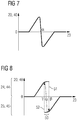
- FIG. 7 shows a graph of a prior art behaviour of yaw angle control in which no hysteresis is implemented. This is not directed to the invention but shall be the basis for the explanation of the inventive control.
- the graph shows on the x-axis the wind direction 23, i.e. the inflow wind direction angle taken at the upstream wind turbine 2 or 2'.
- the y-axis shows the rotor yaw offset angle set point 40, and as this is met by the actual setting after the yaw actuating is performed, the y-axis also represents the actual rotor yaw misalignment angle 20.
- a turning wind direction will at some point trigger a yawing to initiate wake deflection.
- a positive offset is triggered and in course of a further turning wind direction the offset increases incrementally. If the wind direction continues to change in the same direction there is the need to switch the orientation of the rotor.
- the point ⁇ may be a switchover angle, at which the new orientation of the yaw state takes place. This continuing the curve from left to right, the negative yaw angles will be set and once a fairly large negative offset is configured, further increasing angles will result in incrementally reducing yaw offset.
- FIG. 8 shows now an exemplary graph of a behaviour of yaw angle control according to the invention.
- the x-axis and y-axis are the same as in FIG. 7 .
- the procedure according to FIG. 8 differs from FIG. 7 that a switchover may not happen at the "perfect" angle ⁇ but the yaw angle may continue to perform incremental changes or even no changes at all, until a first hysteresis threshold with a first switching limit 51 is reached, identified in the curve as angle ⁇ . Then a switchover from positive to negative yaw angles take place, jumping on the graph from the positive rotor yaw offset angle set points 44 to the negative rotor yaw offset angle set points 45. Once the second branch of the graph is met, the curve can be followed with incremental changes in both directions. Further increased wind direction rotation in the same direction as before would continue the curve to the right and the negative rotor yaw offset angle set points 45 would decrease in its absolute value.
- angles ⁇ and ⁇ may be 2.5°, 5° or 10°. This may be dependent on the location of the wind park and how frequently the wind direction changes at the given location.
- the graph shows on the y-axis shows the rotor yaw offset angle set point 40 and positive values represent positive rotor yaw offset angle set points 44 and negative values represent negative rotor yaw offset angle set points 45, Nevertheless, as the actuator will follow the set point setting so that eventually the actual setting is identical to the set point setting, the graph can be understood to also show on the y-axis the actual rotor yaw misalignment angle 20 and positive values represent positive actual rotor yaw misalignment angles 24 and negative values represent negative actual rotor yaw misalignment angles 25.
- FIG. 3 and 4 represent a transition on the negative angle branch of the curve from right to left with increasing absolute angles.
- FIG. 5 represents that the hysteresis threshold ⁇ is reached so that a switchover to positive yaw angles occurs.
- the new orientation according to FIG. 5 is represented by the point on the positive branch of FIG. 8 , to which the arrow of switching limit 52 points.
- the value ⁇ in theory defines the optimal transition point and is positioned between the two switching limits ⁇ and ⁇ .
- a pair of wind turbines is selected as a first wind turbine 2 or 2' that could have an implication on a second turbine 3 or 3'.
- a current yaw state is determined.
- the current yaw state is simply a binary identifier representing whether the actual rotor yaw misalignment angle 20 is either in a range of positive yaw misalignment angles 24 or alternatively of negative yaw misalignment angles 25. So by that the branch on the curve of FIG. 8 is selected.
- the current yaw state can also be identical to the actual rotor yaw misalignment angle 20 of the first wind turbine 2 or 2'.
- the control reflects a level of wake inducement 30 at the second wind turbine 3 or 3' caused at least by the first wind turbine 2 or 2'.
- the level of wake inducement may be a percentage of how much of the rotor area will be negatively affected by the wake.
- the level of wake inducement 30 may also correspond to the distance 31 between locations of the first wind turbine 2 or 2' and the second wind turbine 3 or 3' and/or to the wind direction 23.
- the rotor yaw offset angle set point 40 for the first wind turbine 2 or 2' is defined to follow a hysteresis 50. This is based on the current yaw state, the wind condition - particularly the wind direction -, and the yaw angle hysteresis switching thresholds 51 and 52. Implicitly the rotor yaw offset angle set point 40 is also controlled based on the level of wake inducement 30.
- the yaw angle hysteresis switching thresholds 51 and 52 may itself depend on the level of wake inducement 30 as they define trigger points to reduce the current level of wake inducement.
- a yaw actuator can be triggered to set the actual rotor yaw misalignment angle 20 to the target value of the rotor yaw offset angle set point 40.
- the control cycle would end and at a further point in time a next control cycle will be initiated according the same procedural steps.
- FIG. 9 now illustrates the wind park control topology. This time the wind turbine 2 is shown from the side, showing the hub 62 and the nacelle 67 on top of a tower 63. A yaw actuator 60 is abstractly shown between the nacelle 67 and the tower 63, allowing yawing about a vertical axis of the wind turbine. So an actual rotor yaw misalignment angle 20 can be configured.
- a wind turbine controller 65 may be present for each wind turbine in the wind park.
- the wind turbine controller 65 again will be in communication with a wind park controller 61.
- the wind park controller 61 performs the previously discussed control method, particularly that pairs of turbines are selected, a current yaw state for an upstream turbine is determined, that a level of wake inducement is determined and that a rotor yaw offset angle set point is defined under consideration of a at least one yaw angle hysteresis switching threshold.
- the determined rotor yaw offset angle set point can then be transmitted from the wind park controller 61 to the wind turbine controller 65, which in turn will trigger the yaw actuator 60 to perform the yawing action.
- FIG. 10 abstractly illustrates the wind park controller 61 and its configuration with the look-up-table 66.
- Such a look-up-table 66 may be present for each wind turbine in the wind park 1.
- the look-up table 66 may have multiple input parameters, at least the wind direction and the current yaw state.
- further input parameter could be used, for example wind speed, wind turbulence and/or information about the profile of the ground.
- Output parameters may be the hysteresis threshold values and/or the rotor yaw offset angle set point.
- FIG. 11 now shows a variant of FIG. 8 , in which a curve for a behaviour of yaw angle control is shown for a selected upstream first turbine and for a wider range wind direction angles.
- the x-axis and y-axis are the same as in FIG. 7 or 8 .
- the procedure according to FIG. 11 differs from FIG. 8 that the upstream turbine may create a wake impact on three downstream turbines, downstream from the given upstream turbine. There may be three regions of angles - for each downstream turbine one region - in which a hysteresis can be applied to reduce the number of major yaw angle switching.
- a first hysteresis 501 may be defined for a first downstream wind turbine, with a theoretical "perfect" angle ⁇ 1 a first hysteresis threshold with a first switching limit 511 is reached, identified in the curve as angle ⁇ 1.
- the given control method may define pairs of hysteresis switching thresholds for each potential downstream wind turbine for a given upstream turbine.
- the above discussed solution provides a hysteresis characteristic or hysteresis behaviour when switching between negative and positive yaw angles.
- switching a major change of angle is meant, not only incremental changes passing through angle of zero.
- the switchover angle for the yaw in reference to the wind direction may be for example +25° and the target angle set point may be -20°.
- switching shall be an incremental transition from +0.1° via 0° to -0.1° or similar values close around 0°.
- a hysteresis can allow to reduce the number of such switching actions.
- a hysteresis implementation with multiple transition angles can be implemented.
- a distance to the closest source for a wake can be calculated or derived.
- a state of look-up-table selection may be calculated as a function of the current state and the distance from the wake creating wind turbine.
- the look-up-table may be a function that defines yaw angles as a function of at least wind direction and possibly other parameters affecting wake deflection.
- the hysteresis function will allow a sharp transition between positive and negative yaw angles to steer the wake away from a downstream turbine in varying wind directions but preventing rapidly repeating transitions between positive and negative reference yaw angles, which the yaw actuator might not be able to track.
- the curve as depicted in FIG. 8 may be optimized and derived using model-based optimization based on a wake model, using constraints on the yaw angles to keep them negative or positive.
- the selection of one of the two curve branches is a function of the turbine alignment angle and a function of the current yaw state of selection. By this a hysteresis is introduced.
Landscapes
- Engineering & Computer Science (AREA)
- Life Sciences & Earth Sciences (AREA)
- Sustainable Development (AREA)
- Sustainable Energy (AREA)
- Chemical & Material Sciences (AREA)
- Combustion & Propulsion (AREA)
- Mechanical Engineering (AREA)
- General Engineering & Computer Science (AREA)
- Wind Motors (AREA)
Priority Applications (8)
| Application Number | Priority Date | Filing Date | Title |
|---|---|---|---|
| EP18193507.3A EP3620649A1 (fr) | 2018-09-10 | 2018-09-10 | Commande d'éoliennes en présence de sillage |
| US17/273,380 US11668279B2 (en) | 2018-09-10 | 2019-09-06 | Controlling wind turbines in presence of wake implications |
| EP19778807.8A EP3827167B1 (fr) | 2018-09-10 | 2019-09-06 | Commande d'éoliennes en présence de sillage |
| CN201980074066.6A CN112955652A (zh) | 2018-09-10 | 2019-09-06 | 在存在尾流影响的情况下控制风力涡轮机 |
| DK19778807.8T DK3827167T3 (da) | 2018-09-10 | 2019-09-06 | Styring af vindmøller i tilstedeværelse af hvirvelstrømsimplikationer |
| PCT/EP2019/073860 WO2020053096A1 (fr) | 2018-09-10 | 2019-09-06 | Commande d'éoliennes en présence d'implications de sillage |
| KR1020217010378A KR20210054568A (ko) | 2018-09-10 | 2019-09-06 | 후류 영향들의 존재 시의 풍력 터빈들의 제어 |
| BR112021003782-9A BR112021003782A2 (pt) | 2018-09-10 | 2019-09-06 | controlador de parque eólico , método de controle, e parque eólico. |
Applications Claiming Priority (1)
| Application Number | Priority Date | Filing Date | Title |
|---|---|---|---|
| EP18193507.3A EP3620649A1 (fr) | 2018-09-10 | 2018-09-10 | Commande d'éoliennes en présence de sillage |
Publications (1)
| Publication Number | Publication Date |
|---|---|
| EP3620649A1 true EP3620649A1 (fr) | 2020-03-11 |
Family
ID=63556228
Family Applications (2)
| Application Number | Title | Priority Date | Filing Date |
|---|---|---|---|
| EP18193507.3A Withdrawn EP3620649A1 (fr) | 2018-09-10 | 2018-09-10 | Commande d'éoliennes en présence de sillage |
| EP19778807.8A Not-in-force EP3827167B1 (fr) | 2018-09-10 | 2019-09-06 | Commande d'éoliennes en présence de sillage |
Family Applications After (1)
| Application Number | Title | Priority Date | Filing Date |
|---|---|---|---|
| EP19778807.8A Not-in-force EP3827167B1 (fr) | 2018-09-10 | 2019-09-06 | Commande d'éoliennes en présence de sillage |
Country Status (7)
| Country | Link |
|---|---|
| US (1) | US11668279B2 (fr) |
| EP (2) | EP3620649A1 (fr) |
| KR (1) | KR20210054568A (fr) |
| CN (1) | CN112955652A (fr) |
| BR (1) | BR112021003782A2 (fr) |
| DK (1) | DK3827167T3 (fr) |
| WO (1) | WO2020053096A1 (fr) |
Cited By (8)
| Publication number | Priority date | Publication date | Assignee | Title |
|---|---|---|---|---|
| CN111980857A (zh) * | 2020-08-26 | 2020-11-24 | 上海电气风电集团股份有限公司 | 风电场的闭环控制方法及其装置及计算机可读存储介质 |
| CN113431738A (zh) * | 2021-08-02 | 2021-09-24 | 哈电风能有限公司 | 风电机组偏航控制方法及系统 |
| CN114254527A (zh) * | 2022-03-01 | 2022-03-29 | 浙江中自庆安新能源技术有限公司 | 一种风力发电机尾流评估方法及系统 |
| KR20220108556A (ko) * | 2021-01-27 | 2022-08-03 | 한국과학기술원 | 웨이크 완화를 위한 풍력터빈시스템 및 풍력터빈 |
| CN117028150A (zh) * | 2023-08-17 | 2023-11-10 | 贵州众联新能源科技有限公司 | 一种风力发电机组区时域化策略的偏航控制方法 |
| WO2024240317A1 (fr) * | 2023-05-23 | 2024-11-28 | Vestas Wind Systems A/S | Procédé de guidage de sillage d'éolienne |
| CN119508136A (zh) * | 2024-11-25 | 2025-02-25 | 华电新能源集团股份有限公司福清分公司 | 基于最大流分析的风电机组控制优化方法与系统 |
| US12535052B2 (en) | 2020-04-16 | 2026-01-27 | Vestas Wind Systems A/S | Wind farm wake control activation method |
Families Citing this family (9)
| Publication number | Priority date | Publication date | Assignee | Title |
|---|---|---|---|---|
| NL2024238B1 (en) * | 2019-11-14 | 2021-07-29 | Univ Delft Tech | Enhanced wind turbine wake mixing |
| CN112459965B (zh) * | 2020-11-18 | 2022-03-01 | 上海电气风电集团股份有限公司 | 考虑风电场尾流的偏航优化控制方法、装置、设备及介质 |
| KR102406851B1 (ko) * | 2021-02-18 | 2022-06-10 | 군산대학교산학협력단 | 확장 가능한 웨이크 방향 그래프를 이용한 풍력 발전 단지의 전력 조정 최적화 방법 및 이를 수행하는 장치 |
| ES3017814T3 (en) | 2021-08-25 | 2025-05-13 | Vestas Wind Sys As | Identifying recurrent free-flow wind disturbances associated with a wind turbine |
| CN117150323B (zh) * | 2023-06-14 | 2025-12-09 | 浙江浙能嘉兴海上风力发电有限公司 | 一种基于风场尾流模型的机群划分方法 |
| US12429029B2 (en) | 2023-09-19 | 2025-09-30 | Tempest Energy Systems, LLC | Wind turbine system |
| CN121969831A (zh) | 2023-10-05 | 2026-05-01 | 维斯塔斯风力系统集团公司 | 对风力涡轮机进行尾流转向的方法 |
| KR102765073B1 (ko) | 2024-11-08 | 2025-02-06 | 고등기술연구원연구조합 | 수직축 풍력터빈 시스템의 블레이드 지지대 피치 제어 장치 |
| CN120120186A (zh) * | 2025-05-13 | 2025-06-10 | 浙江省白马湖实验室有限公司 | 一种风电场尾流的梯次优化控制方法及系统 |
Citations (3)
| Publication number | Priority date | Publication date | Assignee | Title |
|---|---|---|---|---|
| EP2314869A1 (fr) * | 2008-10-29 | 2011-04-27 | Mitsubishi Heavy Industries, Ltd. | Générateur d'énergie éolienne, et procédé de commande associé |
| EP2767710A2 (fr) * | 2013-02-19 | 2014-08-20 | Siemens Aktiengesellschaft | Méthode et système pour améliorer l'efficacité de la production d'énergie d'un parc éolien |
| EP3037657A1 (fr) * | 2014-12-23 | 2016-06-29 | ABB Technology AG | Fonctionnement optimal de parc éolien |
Family Cites Families (10)
| Publication number | Priority date | Publication date | Assignee | Title |
|---|---|---|---|---|
| US20090099702A1 (en) * | 2007-10-16 | 2009-04-16 | General Electric Company | System and method for optimizing wake interaction between wind turbines |
| US7931445B2 (en) * | 2009-11-05 | 2011-04-26 | General Electric Company | Apparatus and method for cleaning an active flow control (AFC) system of a wind turbine |
| US20130317748A1 (en) * | 2012-05-22 | 2013-11-28 | John M. Obrecht | Method and system for wind velocity field measurements on a wind farm |
| WO2015039665A1 (fr) * | 2013-09-17 | 2015-03-26 | Vestas Wind Systems A/S | Procédé de commande de turbine éolienne |
| US20160215759A1 (en) * | 2015-01-28 | 2016-07-28 | Alliance For Sustainable Energy, Llc | Methods and systems for wind plant power optimization |
| ES2794827T3 (es) * | 2016-06-30 | 2020-11-19 | Vestas Wind Sys As | Método de control para una turbina eólica |
| US10465655B2 (en) * | 2016-07-05 | 2019-11-05 | Inventus Holdings, Llc | Wind turbine wake steering apparatus |
| EP3533997A1 (fr) | 2018-02-28 | 2019-09-04 | Siemens Gamesa Renewable Energy A/S | Estimation de débit entrant à jet libre dans une éolienne |
| EP3536948A1 (fr) | 2018-03-08 | 2019-09-11 | Siemens Gamesa Renewable Energy A/S | Détermination des réglages de commande pour éolienne |
| EP3578808A1 (fr) | 2018-06-08 | 2019-12-11 | Siemens Gamesa Renewable Energy A/S | Commande d'éoliennes en présence d'interactions de sillage |
-
2018
- 2018-09-10 EP EP18193507.3A patent/EP3620649A1/fr not_active Withdrawn
-
2019
- 2019-09-06 EP EP19778807.8A patent/EP3827167B1/fr not_active Not-in-force
- 2019-09-06 WO PCT/EP2019/073860 patent/WO2020053096A1/fr not_active Ceased
- 2019-09-06 CN CN201980074066.6A patent/CN112955652A/zh active Pending
- 2019-09-06 KR KR1020217010378A patent/KR20210054568A/ko not_active Ceased
- 2019-09-06 DK DK19778807.8T patent/DK3827167T3/da active
- 2019-09-06 US US17/273,380 patent/US11668279B2/en active Active
- 2019-09-06 BR BR112021003782-9A patent/BR112021003782A2/pt not_active Application Discontinuation
Patent Citations (3)
| Publication number | Priority date | Publication date | Assignee | Title |
|---|---|---|---|---|
| EP2314869A1 (fr) * | 2008-10-29 | 2011-04-27 | Mitsubishi Heavy Industries, Ltd. | Générateur d'énergie éolienne, et procédé de commande associé |
| EP2767710A2 (fr) * | 2013-02-19 | 2014-08-20 | Siemens Aktiengesellschaft | Méthode et système pour améliorer l'efficacité de la production d'énergie d'un parc éolien |
| EP3037657A1 (fr) * | 2014-12-23 | 2016-06-29 | ABB Technology AG | Fonctionnement optimal de parc éolien |
Non-Patent Citations (1)
| Title |
|---|
| PARK JINKYOO ET AL: "A data-driven, cooperative wind farm control to maximize the total power production", APPLIED ENERGY, ELSEVIER SCIENCE PUBLISHERS, GB, vol. 165, 31 December 2015 (2015-12-31), pages 151 - 165, XP029400213, ISSN: 0306-2619, DOI: 10.1016/J.APENERGY.2015.11.064 * |
Cited By (10)
| Publication number | Priority date | Publication date | Assignee | Title |
|---|---|---|---|---|
| US12535052B2 (en) | 2020-04-16 | 2026-01-27 | Vestas Wind Systems A/S | Wind farm wake control activation method |
| CN111980857A (zh) * | 2020-08-26 | 2020-11-24 | 上海电气风电集团股份有限公司 | 风电场的闭环控制方法及其装置及计算机可读存储介质 |
| KR20220108556A (ko) * | 2021-01-27 | 2022-08-03 | 한국과학기술원 | 웨이크 완화를 위한 풍력터빈시스템 및 풍력터빈 |
| CN113431738A (zh) * | 2021-08-02 | 2021-09-24 | 哈电风能有限公司 | 风电机组偏航控制方法及系统 |
| CN114254527A (zh) * | 2022-03-01 | 2022-03-29 | 浙江中自庆安新能源技术有限公司 | 一种风力发电机尾流评估方法及系统 |
| CN114254527B (zh) * | 2022-03-01 | 2022-06-28 | 浙江中自庆安新能源技术有限公司 | 一种风力发电机尾流评估方法及系统 |
| WO2024240317A1 (fr) * | 2023-05-23 | 2024-11-28 | Vestas Wind Systems A/S | Procédé de guidage de sillage d'éolienne |
| CN117028150A (zh) * | 2023-08-17 | 2023-11-10 | 贵州众联新能源科技有限公司 | 一种风力发电机组区时域化策略的偏航控制方法 |
| CN117028150B (zh) * | 2023-08-17 | 2024-04-19 | 贵州众联新能源科技有限公司 | 一种风力发电机组区时域化策略的偏航控制方法 |
| CN119508136A (zh) * | 2024-11-25 | 2025-02-25 | 华电新能源集团股份有限公司福清分公司 | 基于最大流分析的风电机组控制优化方法与系统 |
Also Published As
| Publication number | Publication date |
|---|---|
| US11668279B2 (en) | 2023-06-06 |
| BR112021003782A2 (pt) | 2021-05-18 |
| EP3827167A1 (fr) | 2021-06-02 |
| DK3827167T3 (da) | 2022-08-08 |
| KR20210054568A (ko) | 2021-05-13 |
| EP3827167B1 (fr) | 2022-07-27 |
| WO2020053096A1 (fr) | 2020-03-19 |
| CN112955652A (zh) | 2021-06-11 |
| US20210207580A1 (en) | 2021-07-08 |
Similar Documents
| Publication | Publication Date | Title |
|---|---|---|
| EP3827167B1 (fr) | Commande d'éoliennes en présence de sillage | |
| EP3237752B1 (fr) | Fonctionnement optimal de parc éolien | |
| CN110520620B (zh) | 用于在风力涡轮机叶片变桨距轴承上减小负载的方法 | |
| US10677220B2 (en) | Wind turbine power generating apparatus and method of operating the same | |
| US20130045098A1 (en) | Cyclic Pitch Control System for Wind Turbine Blades | |
| US20100226772A1 (en) | Blade control system | |
| US20140297052A1 (en) | Method of operating a wind turbine | |
| US12264650B2 (en) | Method for controlling an offshore floating tower wind turbine, and control system and wind turbine that use the method | |
| US9523343B2 (en) | Power-conversion installation including a hydraulic machine provided with a runner | |
| EP3473851B1 (fr) | Générateur de turbine éolienne | |
| WO2019163325A1 (fr) | Dispositif de production d'énergie éolienne et procédé de commande pour ledit dispositif | |
| EP4136340B1 (fr) | Procédé d'activation de commande de sillage de parc éolien | |
| CA2828148A1 (fr) | Centrale electrique destinee a produire de l'energie a partir d'un ecoulement d'eau et procede permettant d'exploiter ladite centrale | |
| AU2019323106B2 (en) | Reversible pump turbine and guide vane for the reversible pump turbine | |
| KR102018579B1 (ko) | 풍력터빈 제어시스템의 피치제어기 | |
| EP3076011B1 (fr) | Procédé de fonctionnement d'une éolienne | |
| EP4097349B1 (fr) | Éolienne comprenant une surface balayée variable et procédé de commande d'une éolienne | |
| KR20150019461A (ko) | 풍력발전시스템 및 그것의 구동 정지 방법 | |
| WO2019163326A1 (fr) | Dispositif de production d'énergie éolienne et procédé de commande pour ledit dispositif | |
| EP3362684B1 (fr) | Système de commande de calage pour le calage d'une pale d'éolienne | |
| CN101498280B (zh) | 用于停止风力涡轮机的方法 | |
| WO2019171829A1 (fr) | Procédé de commande de générateur éolien | |
| KR102884336B1 (ko) | 플레트너 로터 동력 감소를 위한 가변 피치형 회전 날개 장치 | |
| JP2017180153A (ja) | 風力発電装置またはウィンドファーム | |
| EP4308815B1 (fr) | Procédé pour commander une éolienne amont dans un parc éolien |
Legal Events
| Date | Code | Title | Description |
|---|---|---|---|
| PUAI | Public reference made under article 153(3) epc to a published international application that has entered the european phase |
Free format text: ORIGINAL CODE: 0009012 |
|
| AK | Designated contracting states |
Kind code of ref document: A1 Designated state(s): AL AT BE BG CH CY CZ DE DK EE ES FI FR GB GR HR HU IE IS IT LI LT LU LV MC MK MT NL NO PL PT RO RS SE SI SK SM TR |
|
| AX | Request for extension of the european patent |
Extension state: BA ME |
|
| STAA | Information on the status of an ep patent application or granted ep patent |
Free format text: STATUS: THE APPLICATION IS DEEMED TO BE WITHDRAWN |
|
| 18D | Application deemed to be withdrawn |
Effective date: 20200912 |