EP3620683B1 - Mr-trägervorrichtung mit einem polymeren blattentkoppler - Google Patents
Mr-trägervorrichtung mit einem polymeren blattentkoppler Download PDFInfo
- Publication number
- EP3620683B1 EP3620683B1 EP19194247.3A EP19194247A EP3620683B1 EP 3620683 B1 EP3620683 B1 EP 3620683B1 EP 19194247 A EP19194247 A EP 19194247A EP 3620683 B1 EP3620683 B1 EP 3620683B1
- Authority
- EP
- European Patent Office
- Prior art keywords
- moving member
- decoupler
- disposed
- center axis
- mount apparatus
- Prior art date
- Legal status (The legal status is an assumption and is not a legal conclusion. Google has not performed a legal analysis and makes no representation as to the accuracy of the status listed.)
- Active
Links
Images


Classifications
-
- F—MECHANICAL ENGINEERING; LIGHTING; HEATING; WEAPONS; BLASTING
- F16—ENGINEERING ELEMENTS AND UNITS; GENERAL MEASURES FOR PRODUCING AND MAINTAINING EFFECTIVE FUNCTIONING OF MACHINES OR INSTALLATIONS; THERMAL INSULATION IN GENERAL
- F16F—SPRINGS; SHOCK-ABSORBERS; MEANS FOR DAMPING VIBRATION
- F16F9/00—Springs, vibration-dampers, shock-absorbers, or similarly-constructed movement-dampers using a fluid or the equivalent as damping medium
- F16F9/32—Details
- F16F9/53—Means for adjusting damping characteristics by varying fluid viscosity, e.g. electromagnetically
-
- F—MECHANICAL ENGINEERING; LIGHTING; HEATING; WEAPONS; BLASTING
- F16—ENGINEERING ELEMENTS AND UNITS; GENERAL MEASURES FOR PRODUCING AND MAINTAINING EFFECTIVE FUNCTIONING OF MACHINES OR INSTALLATIONS; THERMAL INSULATION IN GENERAL
- F16F—SPRINGS; SHOCK-ABSORBERS; MEANS FOR DAMPING VIBRATION
- F16F13/00—Units comprising springs of the non-fluid type as well as vibration-dampers, shock-absorbers, or fluid springs
- F16F13/04—Units comprising springs of the non-fluid type as well as vibration-dampers, shock-absorbers, or fluid springs comprising both a plastics spring and a damper, e.g. a friction damper
- F16F13/06—Units comprising springs of the non-fluid type as well as vibration-dampers, shock-absorbers, or fluid springs comprising both a plastics spring and a damper, e.g. a friction damper the damper being a fluid damper, e.g. the plastics spring not forming a part of the wall of the fluid chamber of the damper
- F16F13/08—Units comprising springs of the non-fluid type as well as vibration-dampers, shock-absorbers, or fluid springs comprising both a plastics spring and a damper, e.g. a friction damper the damper being a fluid damper, e.g. the plastics spring not forming a part of the wall of the fluid chamber of the damper the plastics spring forming at least a part of the wall of the fluid chamber of the damper
- F16F13/10—Units comprising springs of the non-fluid type as well as vibration-dampers, shock-absorbers, or fluid springs comprising both a plastics spring and a damper, e.g. a friction damper the damper being a fluid damper, e.g. the plastics spring not forming a part of the wall of the fluid chamber of the damper the plastics spring forming at least a part of the wall of the fluid chamber of the damper the wall being at least in part formed by a flexible membrane or the like
- F16F13/105—Units comprising springs of the non-fluid type as well as vibration-dampers, shock-absorbers, or fluid springs comprising both a plastics spring and a damper, e.g. a friction damper the damper being a fluid damper, e.g. the plastics spring not forming a part of the wall of the fluid chamber of the damper the plastics spring forming at least a part of the wall of the fluid chamber of the damper the wall being at least in part formed by a flexible membrane or the like characterised by features of partitions between two working chambers
-
- B—PERFORMING OPERATIONS; TRANSPORTING
- B60—VEHICLES IN GENERAL
- B60K—ARRANGEMENT OR MOUNTING OF PROPULSION UNITS OR OF TRANSMISSIONS IN VEHICLES; ARRANGEMENT OR MOUNTING OF PLURAL DIVERSE PRIME-MOVERS IN VEHICLES; AUXILIARY DRIVES FOR VEHICLES; INSTRUMENTATION OR DASHBOARDS FOR VEHICLES; ARRANGEMENTS IN CONNECTION WITH COOLING, AIR INTAKE, GAS EXHAUST OR FUEL SUPPLY OF PROPULSION UNITS IN VEHICLES
- B60K5/00—Arrangement or mounting of internal-combustion or jet-propulsion units
- B60K5/12—Arrangement of engine supports
- B60K5/1208—Resilient supports
-
- B—PERFORMING OPERATIONS; TRANSPORTING
- B60—VEHICLES IN GENERAL
- B60K—ARRANGEMENT OR MOUNTING OF PROPULSION UNITS OR OF TRANSMISSIONS IN VEHICLES; ARRANGEMENT OR MOUNTING OF PLURAL DIVERSE PRIME-MOVERS IN VEHICLES; AUXILIARY DRIVES FOR VEHICLES; INSTRUMENTATION OR DASHBOARDS FOR VEHICLES; ARRANGEMENTS IN CONNECTION WITH COOLING, AIR INTAKE, GAS EXHAUST OR FUEL SUPPLY OF PROPULSION UNITS IN VEHICLES
- B60K5/00—Arrangement or mounting of internal-combustion or jet-propulsion units
- B60K5/12—Arrangement of engine supports
- B60K5/1283—Adjustable supports, e.g. the mounting or the characteristics being adjustable
-
- B—PERFORMING OPERATIONS; TRANSPORTING
- B62—LAND VEHICLES FOR TRAVELLING OTHERWISE THAN ON RAILS
- B62D—MOTOR VEHICLES; TRAILERS
- B62D21/00—Understructures, i.e. chassis frame on which a vehicle body may be mounted
- B62D21/11—Understructures, i.e. chassis frame on which a vehicle body may be mounted with resilient means for suspension, e.g. of wheels or engine; sub-frames for mounting engine or suspensions
-
- B—PERFORMING OPERATIONS; TRANSPORTING
- B62—LAND VEHICLES FOR TRAVELLING OTHERWISE THAN ON RAILS
- B62D—MOTOR VEHICLES; TRAILERS
- B62D29/00—Superstructures, understructures, or sub-units thereof, characterised by the material thereof
- B62D29/04—Superstructures, understructures, or sub-units thereof, characterised by the material thereof predominantly of synthetic material
- B62D29/048—Connections therefor, e.g. joints
-
- F—MECHANICAL ENGINEERING; LIGHTING; HEATING; WEAPONS; BLASTING
- F16—ENGINEERING ELEMENTS AND UNITS; GENERAL MEASURES FOR PRODUCING AND MAINTAINING EFFECTIVE FUNCTIONING OF MACHINES OR INSTALLATIONS; THERMAL INSULATION IN GENERAL
- F16F—SPRINGS; SHOCK-ABSORBERS; MEANS FOR DAMPING VIBRATION
- F16F13/00—Units comprising springs of the non-fluid type as well as vibration-dampers, shock-absorbers, or fluid springs
- F16F13/04—Units comprising springs of the non-fluid type as well as vibration-dampers, shock-absorbers, or fluid springs comprising both a plastics spring and a damper, e.g. a friction damper
- F16F13/06—Units comprising springs of the non-fluid type as well as vibration-dampers, shock-absorbers, or fluid springs comprising both a plastics spring and a damper, e.g. a friction damper the damper being a fluid damper, e.g. the plastics spring not forming a part of the wall of the fluid chamber of the damper
- F16F13/08—Units comprising springs of the non-fluid type as well as vibration-dampers, shock-absorbers, or fluid springs comprising both a plastics spring and a damper, e.g. a friction damper the damper being a fluid damper, e.g. the plastics spring not forming a part of the wall of the fluid chamber of the damper the plastics spring forming at least a part of the wall of the fluid chamber of the damper
- F16F13/10—Units comprising springs of the non-fluid type as well as vibration-dampers, shock-absorbers, or fluid springs comprising both a plastics spring and a damper, e.g. a friction damper the damper being a fluid damper, e.g. the plastics spring not forming a part of the wall of the fluid chamber of the damper the plastics spring forming at least a part of the wall of the fluid chamber of the damper the wall being at least in part formed by a flexible membrane or the like
- F16F13/105—Units comprising springs of the non-fluid type as well as vibration-dampers, shock-absorbers, or fluid springs comprising both a plastics spring and a damper, e.g. a friction damper the damper being a fluid damper, e.g. the plastics spring not forming a part of the wall of the fluid chamber of the damper the plastics spring forming at least a part of the wall of the fluid chamber of the damper the wall being at least in part formed by a flexible membrane or the like characterised by features of partitions between two working chambers
- F16F13/106—Design of constituent elastomeric parts, e.g. decoupling valve elements, or of immediate abutments therefor, e.g. cages
-
- F—MECHANICAL ENGINEERING; LIGHTING; HEATING; WEAPONS; BLASTING
- F16—ENGINEERING ELEMENTS AND UNITS; GENERAL MEASURES FOR PRODUCING AND MAINTAINING EFFECTIVE FUNCTIONING OF MACHINES OR INSTALLATIONS; THERMAL INSULATION IN GENERAL
- F16F—SPRINGS; SHOCK-ABSORBERS; MEANS FOR DAMPING VIBRATION
- F16F13/00—Units comprising springs of the non-fluid type as well as vibration-dampers, shock-absorbers, or fluid springs
- F16F13/04—Units comprising springs of the non-fluid type as well as vibration-dampers, shock-absorbers, or fluid springs comprising both a plastics spring and a damper, e.g. a friction damper
- F16F13/26—Units comprising springs of the non-fluid type as well as vibration-dampers, shock-absorbers, or fluid springs comprising both a plastics spring and a damper, e.g. a friction damper characterised by adjusting or regulating devices responsive to exterior conditions
- F16F13/264—Units comprising springs of the non-fluid type as well as vibration-dampers, shock-absorbers, or fluid springs comprising both a plastics spring and a damper, e.g. a friction damper characterised by adjusting or regulating devices responsive to exterior conditions comprising means for acting dynamically on the walls bounding a working chamber
-
- F—MECHANICAL ENGINEERING; LIGHTING; HEATING; WEAPONS; BLASTING
- F16—ENGINEERING ELEMENTS AND UNITS; GENERAL MEASURES FOR PRODUCING AND MAINTAINING EFFECTIVE FUNCTIONING OF MACHINES OR INSTALLATIONS; THERMAL INSULATION IN GENERAL
- F16F—SPRINGS; SHOCK-ABSORBERS; MEANS FOR DAMPING VIBRATION
- F16F13/00—Units comprising springs of the non-fluid type as well as vibration-dampers, shock-absorbers, or fluid springs
- F16F13/04—Units comprising springs of the non-fluid type as well as vibration-dampers, shock-absorbers, or fluid springs comprising both a plastics spring and a damper, e.g. a friction damper
- F16F13/26—Units comprising springs of the non-fluid type as well as vibration-dampers, shock-absorbers, or fluid springs comprising both a plastics spring and a damper, e.g. a friction damper characterised by adjusting or regulating devices responsive to exterior conditions
- F16F13/30—Units comprising springs of the non-fluid type as well as vibration-dampers, shock-absorbers, or fluid springs comprising both a plastics spring and a damper, e.g. a friction damper characterised by adjusting or regulating devices responsive to exterior conditions comprising means for varying fluid viscosity, e.g. of magnetic or electrorheological fluids
- F16F13/305—Units comprising springs of the non-fluid type as well as vibration-dampers, shock-absorbers, or fluid springs comprising both a plastics spring and a damper, e.g. a friction damper characterised by adjusting or regulating devices responsive to exterior conditions comprising means for varying fluid viscosity, e.g. of magnetic or electrorheological fluids magnetorheological
-
- F—MECHANICAL ENGINEERING; LIGHTING; HEATING; WEAPONS; BLASTING
- F16—ENGINEERING ELEMENTS AND UNITS; GENERAL MEASURES FOR PRODUCING AND MAINTAINING EFFECTIVE FUNCTIONING OF MACHINES OR INSTALLATIONS; THERMAL INSULATION IN GENERAL
- F16F—SPRINGS; SHOCK-ABSORBERS; MEANS FOR DAMPING VIBRATION
- F16F9/00—Springs, vibration-dampers, shock-absorbers, or similarly-constructed movement-dampers using a fluid or the equivalent as damping medium
- F16F9/10—Springs, vibration-dampers, shock-absorbers, or similarly-constructed movement-dampers using a fluid or the equivalent as damping medium using liquid only; using a fluid of which the nature is immaterial
-
- F—MECHANICAL ENGINEERING; LIGHTING; HEATING; WEAPONS; BLASTING
- F16—ENGINEERING ELEMENTS AND UNITS; GENERAL MEASURES FOR PRODUCING AND MAINTAINING EFFECTIVE FUNCTIONING OF MACHINES OR INSTALLATIONS; THERMAL INSULATION IN GENERAL
- F16F—SPRINGS; SHOCK-ABSORBERS; MEANS FOR DAMPING VIBRATION
- F16F13/00—Units comprising springs of the non-fluid type as well as vibration-dampers, shock-absorbers, or fluid springs
- F16F13/04—Units comprising springs of the non-fluid type as well as vibration-dampers, shock-absorbers, or fluid springs comprising both a plastics spring and a damper, e.g. a friction damper
- F16F13/26—Units comprising springs of the non-fluid type as well as vibration-dampers, shock-absorbers, or fluid springs comprising both a plastics spring and a damper, e.g. a friction damper characterised by adjusting or regulating devices responsive to exterior conditions
- F16F13/30—Units comprising springs of the non-fluid type as well as vibration-dampers, shock-absorbers, or fluid springs comprising both a plastics spring and a damper, e.g. a friction damper characterised by adjusting or regulating devices responsive to exterior conditions comprising means for varying fluid viscosity, e.g. of magnetic or electrorheological fluids
-
- F—MECHANICAL ENGINEERING; LIGHTING; HEATING; WEAPONS; BLASTING
- F16—ENGINEERING ELEMENTS AND UNITS; GENERAL MEASURES FOR PRODUCING AND MAINTAINING EFFECTIVE FUNCTIONING OF MACHINES OR INSTALLATIONS; THERMAL INSULATION IN GENERAL
- F16F—SPRINGS; SHOCK-ABSORBERS; MEANS FOR DAMPING VIBRATION
- F16F2222/00—Special physical effects, e.g. nature of damping effects
- F16F2222/06—Magnetic or electromagnetic
-
- F—MECHANICAL ENGINEERING; LIGHTING; HEATING; WEAPONS; BLASTING
- F16—ENGINEERING ELEMENTS AND UNITS; GENERAL MEASURES FOR PRODUCING AND MAINTAINING EFFECTIVE FUNCTIONING OF MACHINES OR INSTALLATIONS; THERMAL INSULATION IN GENERAL
- F16F—SPRINGS; SHOCK-ABSORBERS; MEANS FOR DAMPING VIBRATION
- F16F2222/00—Special physical effects, e.g. nature of damping effects
- F16F2222/12—Fluid damping
-
- F—MECHANICAL ENGINEERING; LIGHTING; HEATING; WEAPONS; BLASTING
- F16—ENGINEERING ELEMENTS AND UNITS; GENERAL MEASURES FOR PRODUCING AND MAINTAINING EFFECTIVE FUNCTIONING OF MACHINES OR INSTALLATIONS; THERMAL INSULATION IN GENERAL
- F16F—SPRINGS; SHOCK-ABSORBERS; MEANS FOR DAMPING VIBRATION
- F16F2228/00—Functional characteristics, e.g. variability, frequency-dependence
- F16F2228/001—Specific functional characteristics in numerical form or in the form of equations
- F16F2228/005—Material properties, e.g. moduli
Definitions
- the present invention generally relates to a hydraulic mount apparatus.
- mounts exist for supporting and providing vibration isolation of vibration sources.
- One well-known application of these mounts is for supporting components of automotive vehicles.
- These mounts typically operate to provide engine vibration isolation while also to control the motion of the engine and connected powertrain components with respect to the vehicle frame or body structure.
- the hydraulic mount apparatus includes a housing having an upper portion and a lower portion disposed on a center axis and defining a housing chamber.
- a partition member is disposed in the housing chamber dividing the housing chamber into a pumping chamber and a receiving chamber.
- the pumping chamber extends between the upper portion and the partition member.
- the receiving chamber extends between the lower portion and the partition member.
- a decoupler is attached to the partition member separating the pumping chamber and the receiving chamber.
- a moving member of elastomeric material disposed in the pumping chamber attached to the decoupler.
- metallic inserts are embedded in the moving member to allow a user to change the stiffness of the moving member.
- the inclusion of the metallic inserts in the moving members increases the manufacturing costs of the hydraulic mount apparatus.
- the elastomeric material and the metallic inserts can chemically react with the fluid in the hydraulic mount apparatus and, thus, reducing the life of the hydraulic mount apparatus.
- Document EP 1099875A1 discloses a method for attenuating vibration, an active hydraulic damping support, and a vehicle comprising such a support.
- the method of damping engine vibrations in a motor vehicle involves using a vibration damping mounting with a rigid diaphragm having an opening closed by a flap which is movable freely at right angles to the opening.
- the flap has one face exposed to the liquid in a working chamber and a second face isolated from the chamber.
- the flap movement is limited by stops to allow variations in volume of the working chamber.
- Patent EP 1081409A1 discloses a valve for a hydroelastic support.
- the suspension unit has a body formed by an elastomer block connecting upper and lower supports, and liquid-filled working and expansion chambers separated by a valve with its outer edge set in a holder.
- the valve has a centre portion or disc made from a rigid material, and an outer ring of a supple material, produced by bi-injection or made separate and joined together by adhesion or mechanical fixing.
- the materials used for the valve components are e.g. rigid or semi-rigid polymers such as thermoplastic or thermo-setting elastomers.
- the present invention provides a hydraulic damper that eliminates the need for metallic inserts in a moving member of a hydraulic mount apparatus.
- the present invention also prevents the moving member from extruding into the compression plate under positive pressure and into the cap under vacuum.
- the present invention further reduces the amount elastomeric material, e.g. rubber, in the moving member thereby improving the life of the hydraulic mount apparatus.
- It is one aspect of the present invention to provide a hydraulic mount apparatus including a housing having an upper portion and a lower portion disposed on a center axis and defining a housing chamber.
- a partition member is disposed in the housing chamber dividing the housing chamber into a pumping chamber and a receiving chamber.
- the pumping chamber extends between the upper portion and the partition member.
- the receiving chamber extends between the lower portion and the partition member.
- a decoupler is attached to the partition member separating the pumping chamber and the receiving chamber.
- a moving member is disposed in the pumping chamber attached to the decoupler.
- the moving member is a non-elastomeric polymer sheet secured to the decoupler for providing the additional damping force.
- the hydraulic mount apparatus further includes a cap disposed in said pumping chamber spaced from said decoupler to secure said moving member between said cap and said decoupler.
- the cap includes a lower plate disposed axially spaced from said moving member and a protrusion extending annularly outwardly from said lower plate toward said decoupler to engage said moving member and secure said moving member to said decoupler.
- the cap includes a rib extending annularly outwardly from said lower plate and parallel to said center axis in a direction opposite of said protrusion with said rib having an inner surface facing said center axis and an outer surface opposite of said inner surface defining a pocket disposed in fluid communication with said pumping chamber between said inner surface and said lower plate.
- the moving member is a die-cut polymer sheet having an outer periphery extending about said center axis.
- the decoupler includes a support member disposed on a center axis and extending between a support member upper end and a support member lower end.
- a moving member is disposed on the center axis, extending radially outwardly from the center axis to the support member upper end, and is attached to the support member upper end.
- the moving member is a non-elastomeric polymer sheet secured to the decoupler for providing the additional damping force.
- the decoupler further includes a cap disposed in said pumping chamber to secure said moving member between said cap and said support member.
- the cap includes a lower plate disposed axially spaced from said moving member and a protrusion extending annularly outwardly from said lower plate toward said support member to engage said moving member and secure said moving member to said support member.
- the cap includes a rib extending annularly outwardly from said lower plate and parallel to said center axis in a direction opposite of said protrusion with said rib having an inner surface facing said center axis and an outer surface opposite of said inner surface defining a pocket disposed in fluid communication with said pumping chamber between said inner surface and said lower plate.
- a hydraulic mount apparatus 20 constructed in accordance with one embodiment of the present invention is generally shown in Figure 1 .
- the hydraulic mount apparatus 20 is used for supporting a component of a vehicle, e.g. an engine, disposed on a frame of the vehicle. It should be appreciated that the hydraulic mount apparatus 20 can be used for supporting various other vibration sources.
- the hydraulic mount apparatus 20 includes a housing 22 having a lower portion 24 and an upper portion 26.
- the lower portion 24 and the upper portion 26 are disposed on a center axis A and axially spaced from one another.
- a wall 28, having a generally tubular shape, is disposed on the center axis A and extends between the lower portion 24 and the upper portion 26 to connect the lower portion 24 with the upper portion 26 and defining a housing chamber 30, 32, 34 extending between the lower portion 24, the upper portion 26, and the wall 28.
- the lower portion 24 having a generally bowl shape, extends annularly about the center axis A between a lower portion closed end 36 and a lower portion opened end 38.
- a lower portion lip 40 extends radially outwardly from the lower portion opened end 38, perpendicular to the center axis A, to engage the wall 28.
- the lower portion 24 includes a collar 42, having a cylindrical shape, disposed on the center axis A.
- the collar 42 extends outwardly from the lower portion closed end 36 and annularly about the center axis A to a distal end 44.
- the collar 42 defines a lower portion bore 46, having a generally cylindrical shape, extending along the center axis A between the lower portion 24 and the distal end 44 for attaching the housing 22 to a vehicle.
- the upper portion 26 having a generally tubular shape, is disposed on the center axis A and axially spaced from the lower portion 24.
- the upper portion 26 extends annularly about the center axis A between a first opened end 48 and a second opened end 50.
- the upper portion 26 defines an upper portion bore 52, having a generally cylindrical shape, extending along the center axis A between the first opened end 48 and the second opened end 50.
- the upper portion 26 includes an upper portion lip 54, disposed at the second opened end 50, and extends radially outwardly from the first opened end 48 in a perpendicular relationship with the center axis A to engage the wall 28. It should be appreciated that the upper portion 26 and the lower portion 24 can have other shapes (e.g. square shaped or hexagonal shaped cross sections).
- a flexible body 56 made from elastomeric material, is disposed in the upper portion bore 52.
- the flexible body 56 extends annularly about and axially along the center axis A from a flexible body lower end 58 to a flexible body upper end 60.
- the flexible body lower end 58 is adjacent to the second opened end 50 of the upper portion 26.
- the flexible body upper end 60 is adjacent to the first opened end 48 of the upper portion 26 for deforming elastically relative to the lower portion 24 in response to an excitation movement of a vehicle.
- the flexible body 56 is attached to the upper portion 26 and deforms in response to an excitation movement of the vehicle, e.g. a vibrational movement.
- the flexible body 56 defines a flexible chamber 62 disposed adjacent to the flexible body upper end 60 extending axially into the flexible body 56 from the flexible body upper end 60.
- the flexible body 56 further defines a pair of insert grooves 64 disposed adjacent to and spaced from the flexible chamber 62 and extending between the flexible body lower end 58 and the flexible body upper end 60.
- a bushing 66 having a generally cylindrical shape, is disposed in the flexible chamber 62 for receiving a fastener to secure the flexible body 56 to the vehicle.
- a pair of outer inserts 68 is disposed in the insert grooves 64 for providing rigidity to the flexible body 56.
- the flexible body 56 includes a flexible body flange 70 extending radially outwardly from the flexible body lower end 58, in a parallel relationship with the upper portion lip 54, for engagement with the upper portion lip 54 to secure the flexible body 56 to the upper portion 54.
- a partition member 72 is disposed in the housing chamber 30, 32, 34, between the upper portion 26 and the lower portion 24, and extends annularly about the center axis A.
- the partitioning member 72 divides the housing chamber 30, 32, 34 into a pumping chamber 30 and a receiving chamber 32, 34.
- the pumping chamber 30 extends between the flexible body 56 and the partition member 72.
- the receiving chamber 32, 34 extends between the lower portion 24 and the partition member 72.
- a magnetorheological fluid can be contained in the pumping chamber 30 and the receiving chamber 32, 34.
- the magnetorheological fluid is responsive to modify its shear properties. More specifically, in responsive to a magnetic field applied to the magnetorheological fluid, the magnetorheological fluid has the ability to modify its shear property from a free-flowing or a viscous liquid to a semi-solid with controllable yield strength.
- a decoupler 74 is disposed in the housing chamber 30, 32, 34 and attached to the partition member 72 to separate the pumping chamber 30 and the receiving chamber 32, 34 and to provide additional damping force in the pumping chamber 30.
- the decoupler 74 includes a support member 76, made from metal and having a generally tubular shape, attached to the partition member 72.
- the support member 76 extends annularly about and along the center axis A between a support member upper end 78 and a support member lower end 80.
- the support member upper end 78 is disposed in the pumping chamber 30.
- the support member lower end 80 is disposed in the receiving chamber 32, 34.
- a support member upper flange 82 extends radially outwardly from the support member upper end 78 and annularly about the center axis A to engage the partition member 72.
- a base 84 having a generally circular shape, is attached to the support member lower end 80 defining a recess 88, having a generally cylindrical shape, extending along the center axis A between the base 84, the support member upper end 78, and the support member lower end 80.
- a support member lower flange 86 extends outwardly from the base 84, along the center axis A, and annularly about the center axis A toward the lower portion to engage the distal end 44 of the collar 42.
- the decoupler 74 includes a moving member 90, having a generally circular shape, disposed on the center axis A in the pumping chamber 30.
- the moving member 90 extends radially outwardly from the center axis A to the support member upper end 78.
- the decoupler 74 is attached to the support member upper end 78 separating the pumping chamber 30 from the receiving chamber 32, 34.
- a diaphragm 92 made from an elastomeric material, is disposed in the receiving chamber 32, 34.
- the diaphragm 92 extends annularly about the center axis A between the lower portion opened end 38 and the distal end 44 of the collar 42.
- the diaphragm 92 is sandwiched between the lower portion 24 and the partition member 72 and the support member lower flange 86 and the distal end 44 of the collar 42 dividing the receiving chamber into a fluid chamber 32 and a compensation chamber 34.
- the fluid chamber 32 extends between the diaphragm 92 and the partition member 72.
- the compensation chamber 34 extends between the lower portion 24 and the diaphragm 92.
- the partition member 72 includes an upper spacer 94, made of metal and having a generally circular shape, disposed in the pumping chamber 30, axially adjacent to and below the upper portion 26, and in engagement with the flexible body flange 70 to sandwich the flexible body flange 70 between the upper portion 26 and the upper spacer 94.
- the upper spacer 94 includes at least one projection 96 extending outwardly from the upper spacer 94 to engage the flexible body flange 70 for securing the flexible body flange 70 between the upper portion 26 and the upper spacer 94.
- the upper spacer 94 defines at least one upper spacer groove 98, disposed opposite of the at least one projection 96 and axially spaced from the at least one projection 96, extending annularly about the center axis A along the upper spacer 94.
- a seal 100 made from an elastomeric material, is disposed in the upper spacer groove 98 and extends annularly about the center axis A.
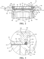
- the moving member 90 is a non-elastomeric polymer sheet secured to the decoupler 74 for providing the additional damping force.
- the moving member 90 having a generally circular shape, is a die cut polymer sheet and having an outer periphery 118 extending about the center axis A. With the moving member 90 being a non-elastomeric polymer, it also minimizes the chemical reaction between the moving member 90 and the magnetorheological fluid thereby prolonging the operation life of the decoupler 74 and the hydraulic mount apparatus 20.
- the cap 120 includes a rib 128 extending annularly outwardly from the lower plate 122 parallel to the center axis A in a direction opposite of the protrusion 124.
- the rib 128 has an inner surface 130 and an outer surface 132.
- the inner surface 120 of the rib 118 is facing the center axis A.
- the outer surface 132 of the rib 128 is disposed on an opposite side from the inner surface 130 and facing the wall 28.
- the cap 120 defines a pocket 134 disposed in fluid communication with the pumping chamber 30.
- the pocket 134 extends between the inner surface 130 of the rib 128 and the lower plate 122.
- the compression plate 140 defines a passage 146 extending through the compression plate 140 for receiving the lead wire 144 to allow the lead wire 144 to extend through the decoupler 74. It should be appreciated that, instead of a lead wire 144, the strain gauge sensor 142 can include a wireless module that can transfer the signals of the stain gauge sensor 142 wirelessly to the user.
- the hydraulic mount apparatus 90 receives an excitation movement, e.g. a vibrational movement, the flexible body 56 deforms thereby causing a change in the volumes of the pumping chamber 30, the fluid chamber 32, and the compensation chamber 34.
- the moving member 90 flexes in the pumping chamber 30 in response to the volume change.
- the moving member 90 provides an additional damping force in the pump chamber 30 in response to the excitation movement.
- the strain gauge sensor 142 records and monitors the moving member 90 and measure the load of the moving member 90 as a function of the movement of the moving member 90.
- the signal generated by the strain gauge sensor 142 is communicated via the lead wire 144 to a user, which allows the user to measure the frequency content of the moving member 90 of the decoupler 74.
Landscapes
- Engineering & Computer Science (AREA)
- General Engineering & Computer Science (AREA)
- Mechanical Engineering (AREA)
- Chemical & Material Sciences (AREA)
- Combustion & Propulsion (AREA)
- Transportation (AREA)
- Physics & Mathematics (AREA)
- Electromagnetism (AREA)
- Architecture (AREA)
- Structural Engineering (AREA)
- Combined Devices Of Dampers And Springs (AREA)
- Arrangement Or Mounting Of Propulsion Units For Vehicles (AREA)
Claims (8)
- Eine hydraulische Befestigungsvorrichtung (20) bestehend aus:einem Gehäuse (22) mit einem oberen Abschnitt (26) und einem unteren Abschnitt (24), die auf einer Mittelachse angeordnet sind und eine Gehäusekammer (30, 32, 34) bilden;einem Trennelement (72), das in der Gehäusekammer (30, 32, 34) angeordnet ist und die Gehäusekammer (30, 32, 34) in eine Pumpkammer (30) und eine Aufnahmekammer (32, 34) unterteilt, wobei die Pumpkammer (30) zwischen dem oberen Abschnitt (26) und dem Trennelement (72) und die Aufnahmekammer (32, 34) zwischen dem unteren Abschnitt (24) und dem Trennelement (72) liegt;einem Entkoppler (74), das an dem Trennelement (72) befestigt ist und die Pumpkammer (30) und die Aufnahmekammer (32, 34) trennt; undeinem beweglichen Element (90), das in der Pumpkammer (30) angeordnet und an dem Entkoppler (74) befestigt ist;wobei das bewegliche Element (90) eine nicht-elastomere Polymerfolie ist, die an dem Entkoppler (74) befestigt ist, um die zusätzliche Dämpfungskraft bereitzustellen,wobei die hydraulische Befestigungsvorrichtung (20) ferner eine Kappe (120) aufweist, die in der Pumpkammer (30) im Abstand von dem Entkoppler (74) angeordnet ist, um das bewegliche Element (90) zwischen der Kappe (120) und dem Entkoppler (74) zu sichern,wobei die Kappe (120) eine untere Platte (122), die axial beabstandet von dem beweglichen Element (90) angeordnet ist, und einen Vorsprung (124) aufweist, der sich ringförmig nach außen von der unteren Platte (122) in Richtung des Entkopplers (74) erstreckt, um mit dem beweglichen Element (90) in Eingriff zu kommen und das bewegliche Element (90) an dem Entkoppler (74) zu befestigen,dadurch gekennzeichnet, dass die Kappe (120) eine Rippe (128) aufweist, die sich von der unteren Platte (122) ringförmig nach außen und parallel zu der Mittelachse in einer Richtung entgegengesetzt zu dem Vorsprung (124) erstreckt, wobei die Rippe (128) eine Innenfläche (130), die der Mittelachse zugewandt ist, und eine Außenfläche (132) gegenüber der Innenfläche (130) aufweist, die eine Tasche (134) definiert, die in Flüssigkeitsverbindung mit der Pumpkammer (30) zwischen der Innenfläche (130) und der unteren Platte (122) angeordnet ist, wobei das bewegliche Element (90) eine gestanzte Polymerfolie mit einem Außenumfang ist, der sich um die Mittelachse erstreckt.
- Die hydraulische Befestigungsvorrichtung (20) nach Anspruch 1, wobei die Außenfläche (132) der Rippe (128) angrenzend an den Außenumfang des beweglichen Elements (90) abgeschrägt ist, um eine Leitung (136) zu bilden, der sich ringförmig um die Mittelachse erstreckt.
- Die hydraulische Befestigungsvorrichtung (20) nach Anspruch 2 umfasst ferner einen O-Ring (138) aus elastomerem Material, der in der Leitung (136) angeordnet ist und sich ringförmig um die Mittelachse und in dichtendem Eingriff mit der Außenfläche (132) und dem Außenumfang (118) des beweglichen Elements (90) erstreckt.
- Die hydraulische Befestigungsvorrichtung (20) nach einem der Ansprüche 1 bis 3 umfasst ferner einen Dehnungsmessstreifensensor (142), der in der Aufnahmekammer (32, 34) angeordnet und an dem beweglichen Element (90) angebracht ist, um eine Last auf das bewegliche Element (90) in Reaktion auf die Bewegung des beweglichen Elements (90) zu messen.
- Die hydraulische Befestigungsvorrichtung (20) nach Anspruch 4, wobei der Entkoppler (74) eine Druckplatte (140) aufweist, die angrenzend an das bewegliche Element (90) und in einem Abstand von diesem auf einer der Kappe (120) gegenüberliegenden Seite angeordnet ist, um die Bewegung des beweglichen Elements (90) zu begrenzen.
- Die hydraulische Befestigungsvorrichtung (20) nach Anspruch 5 umfasst ferner einen Leitungsdraht (144), der elektrisch mit dem Dehnungsmessstreifensensor (142) verbunden ist und sich durch die Druckplatte (140) erstreckt und elektrisch mit einem Prozessor zum Empfangen und Analysieren eines von dem Dehnungsmessstreifensensor (142) empfangenen Signals verbunden ist.
- Die hydraulische Befestigungsvorrichtung (20) nach Anspruch 6, wobei die Druckplatte (140) einen sich durch die Druckplatte (140) erstreckenden Durchgang (146) zur Aufnahme des Leitungsdrahtes (144) definiert, damit sich der Leitungsdraht (144) durch den Entkoppler (74) erstrecken kann.
- Die hydraulische Befestigungsvorrichtung (20) nach Anspruch 1, wobei der Entkoppler (74) ferner ein Stützelement (76) umfasst, das auf einer Mittelachse angeordnet ist und sich zwischen einem oberen Ende (78) und einem unteren Ende (80) des Stützelements erstreckt,
wobei das bewegliche Element (90) auf der Mittelachse angeordnet ist und sich von der Mittelachse radial nach außen zu dem oberen Ende (78) des Stützelements erstreckt und an dem oberen Ende (78) des Stützelements befestigt ist.
Applications Claiming Priority (2)
| Application Number | Priority Date | Filing Date | Title |
|---|---|---|---|
| US201862729344P | 2018-09-10 | 2018-09-10 | |
| CN201910619268.6A CN110397697B (zh) | 2018-09-10 | 2019-07-10 | 液压悬置装置及分离件 |
Publications (2)
| Publication Number | Publication Date |
|---|---|
| EP3620683A1 EP3620683A1 (de) | 2020-03-11 |
| EP3620683B1 true EP3620683B1 (de) | 2025-07-09 |
Family
ID=68324437
Family Applications (1)
| Application Number | Title | Priority Date | Filing Date |
|---|---|---|---|
| EP19194247.3A Active EP3620683B1 (de) | 2018-09-10 | 2019-08-29 | Mr-trägervorrichtung mit einem polymeren blattentkoppler |
Country Status (4)
| Country | Link |
|---|---|
| US (1) | US11274725B2 (de) |
| EP (1) | EP3620683B1 (de) |
| JP (1) | JP6853318B2 (de) |
| CN (1) | CN110397697B (de) |
Families Citing this family (2)
| Publication number | Priority date | Publication date | Assignee | Title |
|---|---|---|---|---|
| USD897374S1 (en) * | 2018-11-03 | 2020-09-29 | North American Aerospace Corporation | Engine mount |
| JP7724734B2 (ja) * | 2022-03-04 | 2025-08-18 | 住友理工株式会社 | 流体封入式防振装置 |
Family Cites Families (30)
| Publication number | Priority date | Publication date | Assignee | Title |
|---|---|---|---|---|
| US4531484A (en) | 1981-11-20 | 1985-07-30 | Nissan Motor Co., Ltd. | Vibration responsive mounting arrangement for automotive engine or the like |
| JPS58118420A (ja) | 1982-01-08 | 1983-07-14 | Nissan Motor Co Ltd | パワ−ユニツトのマウンテイング装置 |
| US4932636A (en) * | 1989-05-12 | 1990-06-12 | General Motors Corporation | Hydraulic-elastomeric mount with bypass through decoupler |
| DE4205353C1 (de) * | 1992-02-21 | 1993-02-18 | Metzeler Gimetall Ag, 8000 Muenchen, De | |
| CA2094208A1 (en) | 1992-04-28 | 1993-10-29 | Richard D. Hein | Prepackaged fluid-damping article for elastomeric mounts and methods of formation and installation |
| US5263693A (en) * | 1992-04-30 | 1993-11-23 | General Motors Corporation | Tiered decoupler for improved high frequency tuning of hydraulic mounts |
| US5246211A (en) * | 1992-07-13 | 1993-09-21 | General Motors Corporation | Hydraulic mount with spring-loaded decoupler for tuned rate dip |
| US5571263A (en) * | 1995-04-14 | 1996-11-05 | General Motors Corporation | Hydraulic engine mount with reduced impulse vibration |
| JP3539067B2 (ja) * | 1996-05-23 | 2004-06-14 | 東海ゴム工業株式会社 | 流体封入式マウント装置 |
| US6082718A (en) | 1997-03-03 | 2000-07-04 | Toyoda Gosei Co., Ltd. | Liquid-sealing type vibration isolating apparatus |
| FR2798175B1 (fr) * | 1999-09-03 | 2002-04-19 | Peugeot Citroen Automobiles Sa | Clapet de support hydroelastique |
| FR2800823B1 (fr) * | 1999-11-09 | 2002-04-05 | Hutchinson | Procede pour attenuer des vibrations, support antivibratoire hydraulique actif, et vehicule comprenant un tel support |
| US6361031B1 (en) | 2000-02-25 | 2002-03-26 | Delphi Technologies, Inc. | Adaptive hydraulic engine mount |
| US6439556B1 (en) * | 2001-02-15 | 2002-08-27 | Delphi Technologies, Inc. | Active decoupler hydraulic mount |
| JP4842078B2 (ja) | 2006-01-31 | 2011-12-21 | 東海ゴム工業株式会社 | 流体封入式防振装置およびその製造方法 |
| FR2908488B1 (fr) | 2006-11-13 | 2009-02-13 | Peugeot Citroen Automobiles Sa | Cale hydroelastique comprenant un actionneur commande electriquement. |
| JP2009103141A (ja) | 2007-10-19 | 2009-05-14 | Toyota Motor Corp | 液体封入式防振装置 |
| US20090243171A1 (en) * | 2008-03-28 | 2009-10-01 | Tokai Rubber Industries, Ltd. | Fluid filled type vibration damping device |
| DE102010060885A1 (de) * | 2010-08-26 | 2012-03-01 | Contitech Vibration Control Gmbh | Motorlager für ein Kraftfahrzeug |
| KR101184283B1 (ko) | 2010-11-30 | 2012-09-21 | 현대자동차주식회사 | Mr유체가 봉입된 댐핑제어장치 및 상기 댐핑제어장치를 구비한 엔진마운트 |
| CN201944188U (zh) * | 2010-12-31 | 2011-08-24 | 宁波泛亚汽车部件有限公司 | 发动机液压悬置 |
| US9051989B2 (en) * | 2011-07-12 | 2015-06-09 | Beijingwest Industries Co., Ltd. | Magnetorheological fluid-based mount apparatus including rate dip track passage |
| JP5616563B2 (ja) * | 2011-07-12 | 2014-10-29 | ベイジンウェスト・インダストリーズ・カンパニー・リミテッドBeijingwest Industries Co., Ltd. | 振動源を支持する液圧マウント装置 |
| JP5595369B2 (ja) * | 2011-12-14 | 2014-09-24 | 東海ゴム工業株式会社 | 流体封入式防振装置 |
| CN102705426A (zh) * | 2012-06-12 | 2012-10-03 | 宁波拓普集团股份有限公司 | 一种新型液压悬置解耦结构 |
| EP3069042A4 (de) * | 2013-11-15 | 2017-07-19 | Cooper-Standard Automotive, Inc. | Verwendung einer induktiven erfassung zur steuerung einer entkopplerposition und einer umschaltbaren montageleistung |
| CN205745062U (zh) * | 2016-05-13 | 2016-11-30 | 上汽通用五菱汽车股份有限公司 | 一种液压悬置用解耦盘 |
| CN107143596B (zh) * | 2016-06-16 | 2019-07-26 | 北京京西重工有限公司 | 用于多级阻尼的组件 |
| US10584761B2 (en) | 2017-01-03 | 2020-03-10 | Beijingwest Industries Co., Ltd. | Vertical decoupler for a hydraulic mount |
| CN110360266B (zh) * | 2018-09-10 | 2020-12-18 | 北京京西重工有限公司 | 液压悬置装置及分离件 |
-
2019
- 2019-07-10 CN CN201910619268.6A patent/CN110397697B/zh active Active
- 2019-08-12 US US16/537,623 patent/US11274725B2/en active Active
- 2019-08-29 EP EP19194247.3A patent/EP3620683B1/de active Active
- 2019-09-06 JP JP2019162669A patent/JP6853318B2/ja active Active
Also Published As
| Publication number | Publication date |
|---|---|
| US11274725B2 (en) | 2022-03-15 |
| US20200080614A1 (en) | 2020-03-12 |
| CN110397697A (zh) | 2019-11-01 |
| EP3620683A1 (de) | 2020-03-11 |
| CN110397697B (zh) | 2021-02-23 |
| JP2020076491A (ja) | 2020-05-21 |
| JP6853318B2 (ja) | 2021-03-31 |
Similar Documents
| Publication | Publication Date | Title |
|---|---|---|
| US4630808A (en) | Vibration isolating devices | |
| EP3620682B1 (de) | Mr-träger mit gummientkoppler mit doppelter härte | |
| US4907786A (en) | Fluid-filled elastic mount having partition member which includes a double-layered section | |
| CN102052425A (zh) | 流体封入式主动型发动机悬置 | |
| JP4348553B2 (ja) | 流体封入式防振装置およびその製造方法 | |
| JP3915531B2 (ja) | 流体封入式防振マウント | |
| EP3620683B1 (de) | Mr-trägervorrichtung mit einem polymeren blattentkoppler | |
| JPH04119649U (ja) | 流体封入式マウント装置 | |
| EP3477150B1 (de) | Hydraulische montagevorrichtung | |
| JP2001234968A (ja) | 流体封入式マウント | |
| JP6240482B2 (ja) | 流体封入式防振装置 | |
| JP4411659B2 (ja) | 流体封入式防振装置 | |
| JP2001336564A (ja) | 流体封入式防振装置 | |
| JP4075066B2 (ja) | 流体封入式エンジンマウント | |
| JP2007139024A (ja) | 流体封入式防振装置 | |
| JP4751740B2 (ja) | 流体封入式防振装置 | |
| JP4623428B2 (ja) | 流体封入式防振装置 | |
| JP2008163970A (ja) | 流体封入式防振装置 | |
| JP5899039B2 (ja) | 流体封入式防振装置 | |
| JP4434500B2 (ja) | 液体封入式マウント | |
| JP2007032745A (ja) | 流体封入式防振装置 | |
| JP2005315375A (ja) | 流体封入式防振装置およびその製造方法 | |
| JP5926108B2 (ja) | 流体封入式防振装置 | |
| JP2007016902A (ja) | 流体封入式防振装置 | |
| JP2007155033A (ja) | 吊下型流体封入式防振装置 |
Legal Events
| Date | Code | Title | Description |
|---|---|---|---|
| PUAI | Public reference made under article 153(3) epc to a published international application that has entered the european phase |
Free format text: ORIGINAL CODE: 0009012 |
|
| STAA | Information on the status of an ep patent application or granted ep patent |
Free format text: STATUS: THE APPLICATION HAS BEEN PUBLISHED |
|
| AK | Designated contracting states |
Kind code of ref document: A1 Designated state(s): AL AT BE BG CH CY CZ DE DK EE ES FI FR GB GR HR HU IE IS IT LI LT LU LV MC MK MT NL NO PL PT RO RS SE SI SK SM TR |
|
| AX | Request for extension of the european patent |
Extension state: BA ME |
|
| STAA | Information on the status of an ep patent application or granted ep patent |
Free format text: STATUS: REQUEST FOR EXAMINATION WAS MADE |
|
| 17P | Request for examination filed |
Effective date: 20200911 |
|
| RBV | Designated contracting states (corrected) |
Designated state(s): AL AT BE BG CH CY CZ DE DK EE ES FI FR GB GR HR HU IE IS IT LI LT LU LV MC MK MT NL NO PL PT RO RS SE SI SK SM TR |
|
| STAA | Information on the status of an ep patent application or granted ep patent |
Free format text: STATUS: EXAMINATION IS IN PROGRESS |
|
| 17Q | First examination report despatched |
Effective date: 20220920 |
|
| GRAP | Despatch of communication of intention to grant a patent |
Free format text: ORIGINAL CODE: EPIDOSNIGR1 |
|
| STAA | Information on the status of an ep patent application or granted ep patent |
Free format text: STATUS: GRANT OF PATENT IS INTENDED |
|
| INTG | Intention to grant announced |
Effective date: 20250129 |
|
| GRAS | Grant fee paid |
Free format text: ORIGINAL CODE: EPIDOSNIGR3 |
|
| GRAA | (expected) grant |
Free format text: ORIGINAL CODE: 0009210 |
|
| STAA | Information on the status of an ep patent application or granted ep patent |
Free format text: STATUS: THE PATENT HAS BEEN GRANTED |
|
| AK | Designated contracting states |
Kind code of ref document: B1 Designated state(s): AL AT BE BG CH CY CZ DE DK EE ES FI FR GB GR HR HU IE IS IT LI LT LU LV MC MK MT NL NO PL PT RO RS SE SI SK SM TR |
|
| REG | Reference to a national code |
Ref country code: GB Ref legal event code: FG4D |
|
| REG | Reference to a national code |
Ref country code: CH Ref legal event code: EP |
|
| REG | Reference to a national code |
Ref country code: IE Ref legal event code: FG4D |
|
| REG | Reference to a national code |
Ref country code: DE Ref legal event code: R096 Ref document number: 602019072223 Country of ref document: DE |
|
| P01 | Opt-out of the competence of the unified patent court (upc) registered |
Free format text: CASE NUMBER: UPC_APP_2197_3620683/2025 Effective date: 20250801 |
|
| PGFP | Annual fee paid to national office [announced via postgrant information from national office to epo] |
Ref country code: DE Payment date: 20250819 Year of fee payment: 7 |
|
| PGFP | Annual fee paid to national office [announced via postgrant information from national office to epo] |
Ref country code: GB Payment date: 20250821 Year of fee payment: 7 |
|
| PGFP | Annual fee paid to national office [announced via postgrant information from national office to epo] |
Ref country code: FR Payment date: 20250821 Year of fee payment: 7 |
|
| REG | Reference to a national code |
Ref country code: NL Ref legal event code: MP Effective date: 20250709 |
|
| PG25 | Lapsed in a contracting state [announced via postgrant information from national office to epo] |
Ref country code: PT Free format text: LAPSE BECAUSE OF FAILURE TO SUBMIT A TRANSLATION OF THE DESCRIPTION OR TO PAY THE FEE WITHIN THE PRESCRIBED TIME-LIMIT Effective date: 20251110 |
|
| PG25 | Lapsed in a contracting state [announced via postgrant information from national office to epo] |
Ref country code: NL Free format text: LAPSE BECAUSE OF FAILURE TO SUBMIT A TRANSLATION OF THE DESCRIPTION OR TO PAY THE FEE WITHIN THE PRESCRIBED TIME-LIMIT Effective date: 20250709 |
|
| REG | Reference to a national code |
Ref country code: AT Ref legal event code: MK05 Ref document number: 1812060 Country of ref document: AT Kind code of ref document: T Effective date: 20250709 |
|
| PG25 | Lapsed in a contracting state [announced via postgrant information from national office to epo] |
Ref country code: IS Free format text: LAPSE BECAUSE OF FAILURE TO SUBMIT A TRANSLATION OF THE DESCRIPTION OR TO PAY THE FEE WITHIN THE PRESCRIBED TIME-LIMIT Effective date: 20251109 |
|
| PG25 | Lapsed in a contracting state [announced via postgrant information from national office to epo] |
Ref country code: NO Free format text: LAPSE BECAUSE OF FAILURE TO SUBMIT A TRANSLATION OF THE DESCRIPTION OR TO PAY THE FEE WITHIN THE PRESCRIBED TIME-LIMIT Effective date: 20251009 |
|
| REG | Reference to a national code |
Ref country code: LT Ref legal event code: MG9D |
|
| PG25 | Lapsed in a contracting state [announced via postgrant information from national office to epo] |
Ref country code: AT Free format text: LAPSE BECAUSE OF FAILURE TO SUBMIT A TRANSLATION OF THE DESCRIPTION OR TO PAY THE FEE WITHIN THE PRESCRIBED TIME-LIMIT Effective date: 20250709 |
|
| PG25 | Lapsed in a contracting state [announced via postgrant information from national office to epo] |
Ref country code: FI Free format text: LAPSE BECAUSE OF FAILURE TO SUBMIT A TRANSLATION OF THE DESCRIPTION OR TO PAY THE FEE WITHIN THE PRESCRIBED TIME-LIMIT Effective date: 20250709 |
|
| PG25 | Lapsed in a contracting state [announced via postgrant information from national office to epo] |
Ref country code: HR Free format text: LAPSE BECAUSE OF FAILURE TO SUBMIT A TRANSLATION OF THE DESCRIPTION OR TO PAY THE FEE WITHIN THE PRESCRIBED TIME-LIMIT Effective date: 20250709 |
|
| PG25 | Lapsed in a contracting state [announced via postgrant information from national office to epo] |
Ref country code: GR Free format text: LAPSE BECAUSE OF FAILURE TO SUBMIT A TRANSLATION OF THE DESCRIPTION OR TO PAY THE FEE WITHIN THE PRESCRIBED TIME-LIMIT Effective date: 20251010 |
|
| PG25 | Lapsed in a contracting state [announced via postgrant information from national office to epo] |
Ref country code: SE Free format text: LAPSE BECAUSE OF FAILURE TO SUBMIT A TRANSLATION OF THE DESCRIPTION OR TO PAY THE FEE WITHIN THE PRESCRIBED TIME-LIMIT Effective date: 20250709 |
|
| PG25 | Lapsed in a contracting state [announced via postgrant information from national office to epo] |
Ref country code: LV Free format text: LAPSE BECAUSE OF FAILURE TO SUBMIT A TRANSLATION OF THE DESCRIPTION OR TO PAY THE FEE WITHIN THE PRESCRIBED TIME-LIMIT Effective date: 20250709 |
|
| PG25 | Lapsed in a contracting state [announced via postgrant information from national office to epo] |
Ref country code: BG Free format text: LAPSE BECAUSE OF FAILURE TO SUBMIT A TRANSLATION OF THE DESCRIPTION OR TO PAY THE FEE WITHIN THE PRESCRIBED TIME-LIMIT Effective date: 20250709 Ref country code: PL Free format text: LAPSE BECAUSE OF FAILURE TO SUBMIT A TRANSLATION OF THE DESCRIPTION OR TO PAY THE FEE WITHIN THE PRESCRIBED TIME-LIMIT Effective date: 20250709 |
|
| PG25 | Lapsed in a contracting state [announced via postgrant information from national office to epo] |
Ref country code: RS Free format text: LAPSE BECAUSE OF FAILURE TO SUBMIT A TRANSLATION OF THE DESCRIPTION OR TO PAY THE FEE WITHIN THE PRESCRIBED TIME-LIMIT Effective date: 20251009 |
|
| PG25 | Lapsed in a contracting state [announced via postgrant information from national office to epo] |
Ref country code: ES Free format text: LAPSE BECAUSE OF FAILURE TO SUBMIT A TRANSLATION OF THE DESCRIPTION OR TO PAY THE FEE WITHIN THE PRESCRIBED TIME-LIMIT Effective date: 20250709 |
|
| PG25 | Lapsed in a contracting state [announced via postgrant information from national office to epo] |
Ref country code: RO Free format text: LAPSE BECAUSE OF FAILURE TO SUBMIT A TRANSLATION OF THE DESCRIPTION OR TO PAY THE FEE WITHIN THE PRESCRIBED TIME-LIMIT Effective date: 20250709 |
|
| REG | Reference to a national code |
Ref country code: CH Ref legal event code: H13 Free format text: ST27 STATUS EVENT CODE: U-0-0-H10-H13 (AS PROVIDED BY THE NATIONAL OFFICE) Effective date: 20260324 |
|
| PG25 | Lapsed in a contracting state [announced via postgrant information from national office to epo] |
Ref country code: SM Free format text: LAPSE BECAUSE OF FAILURE TO SUBMIT A TRANSLATION OF THE DESCRIPTION OR TO PAY THE FEE WITHIN THE PRESCRIBED TIME-LIMIT Effective date: 20250709 |
|
| PG25 | Lapsed in a contracting state [announced via postgrant information from national office to epo] |
Ref country code: DK Free format text: LAPSE BECAUSE OF FAILURE TO SUBMIT A TRANSLATION OF THE DESCRIPTION OR TO PAY THE FEE WITHIN THE PRESCRIBED TIME-LIMIT Effective date: 20250709 |
|
| PG25 | Lapsed in a contracting state [announced via postgrant information from national office to epo] |
Ref country code: LU Free format text: LAPSE BECAUSE OF NON-PAYMENT OF DUE FEES Effective date: 20250829 Ref country code: IT Free format text: LAPSE BECAUSE OF FAILURE TO SUBMIT A TRANSLATION OF THE DESCRIPTION OR TO PAY THE FEE WITHIN THE PRESCRIBED TIME-LIMIT Effective date: 20250709 |
|
| PG25 | Lapsed in a contracting state [announced via postgrant information from national office to epo] |
Ref country code: CZ Free format text: LAPSE BECAUSE OF FAILURE TO SUBMIT A TRANSLATION OF THE DESCRIPTION OR TO PAY THE FEE WITHIN THE PRESCRIBED TIME-LIMIT Effective date: 20250709 Ref country code: CH Free format text: LAPSE BECAUSE OF NON-PAYMENT OF DUE FEES Effective date: 20250831 |
|
| PG25 | Lapsed in a contracting state [announced via postgrant information from national office to epo] |
Ref country code: SK Free format text: LAPSE BECAUSE OF FAILURE TO SUBMIT A TRANSLATION OF THE DESCRIPTION OR TO PAY THE FEE WITHIN THE PRESCRIBED TIME-LIMIT Effective date: 20250709 Ref country code: EE Free format text: LAPSE BECAUSE OF FAILURE TO SUBMIT A TRANSLATION OF THE DESCRIPTION OR TO PAY THE FEE WITHIN THE PRESCRIBED TIME-LIMIT Effective date: 20250709 |