EP3620687B1 - Verbindungsverfahren von zwei verzahnungselementen und antriebsvorrichtung, bei der dieses verfahren angewandt wird - Google Patents
Verbindungsverfahren von zwei verzahnungselementen und antriebsvorrichtung, bei der dieses verfahren angewandt wird Download PDFInfo
- Publication number
- EP3620687B1 EP3620687B1 EP19195739.8A EP19195739A EP3620687B1 EP 3620687 B1 EP3620687 B1 EP 3620687B1 EP 19195739 A EP19195739 A EP 19195739A EP 3620687 B1 EP3620687 B1 EP 3620687B1
- Authority
- EP
- European Patent Office
- Prior art keywords
- gear element
- gear
- sensor
- cylinder
- rod
- Prior art date
- Legal status (The legal status is an assumption and is not a legal conclusion. Google has not performed a legal analysis and makes no representation as to the accuracy of the status listed.)
- Active
Links
Images

Classifications
-
- F—MECHANICAL ENGINEERING; LIGHTING; HEATING; WEAPONS; BLASTING
- F16—ENGINEERING ELEMENTS AND UNITS; GENERAL MEASURES FOR PRODUCING AND MAINTAINING EFFECTIVE FUNCTIONING OF MACHINES OR INSTALLATIONS; THERMAL INSULATION IN GENERAL
- F16H—GEARING
- F16H1/00—Toothed gearings for conveying rotary motion
- F16H1/006—Toothed gearings for conveying rotary motion the driving and driven axes being designed to assume variable positions relative to one another during operation
-
- B—PERFORMING OPERATIONS; TRANSPORTING
- B64—AIRCRAFT; AVIATION; COSMONAUTICS
- B64C—AEROPLANES; HELICOPTERS
- B64C25/00—Alighting gear
- B64C25/02—Undercarriages
- B64C25/08—Undercarriages non-fixed, e.g. jettisonable
- B64C25/10—Undercarriages non-fixed, e.g. jettisonable retractable, foldable, or the like
- B64C25/18—Operating mechanisms
- B64C25/24—Operating mechanisms electric
-
- F—MECHANICAL ENGINEERING; LIGHTING; HEATING; WEAPONS; BLASTING
- F16—ENGINEERING ELEMENTS AND UNITS; GENERAL MEASURES FOR PRODUCING AND MAINTAINING EFFECTIVE FUNCTIONING OF MACHINES OR INSTALLATIONS; THERMAL INSULATION IN GENERAL
- F16H—GEARING
- F16H61/00—Control functions within control units of change-speed- or reversing-gearings for conveying rotary motion ; Control of exclusively fluid gearing, friction gearing, gearings with endless flexible members or other particular types of gearing
- F16H61/26—Generation or transmission of movements for final actuating mechanisms
- F16H61/28—Generation or transmission of movements for final actuating mechanisms with at least one movement of the final actuating mechanism being caused by a non-mechanical force, e.g. power-assisted
-
- B—PERFORMING OPERATIONS; TRANSPORTING
- B64—AIRCRAFT; AVIATION; COSMONAUTICS
- B64C—AEROPLANES; HELICOPTERS
- B64C25/00—Alighting gear
- B64C25/32—Alighting gear characterised by elements which contact the ground or similar surface
- B64C25/405—Powered wheels, e.g. for taxing
-
- F—MECHANICAL ENGINEERING; LIGHTING; HEATING; WEAPONS; BLASTING
- F16—ENGINEERING ELEMENTS AND UNITS; GENERAL MEASURES FOR PRODUCING AND MAINTAINING EFFECTIVE FUNCTIONING OF MACHINES OR INSTALLATIONS; THERMAL INSULATION IN GENERAL
- F16H—GEARING
- F16H1/00—Toothed gearings for conveying rotary motion
- F16H1/02—Toothed gearings for conveying rotary motion without gears having orbital motion
- F16H1/04—Toothed gearings for conveying rotary motion without gears having orbital motion involving only two intermeshing members
- F16H1/06—Toothed gearings for conveying rotary motion without gears having orbital motion involving only two intermeshing members with parallel axes
-
- F—MECHANICAL ENGINEERING; LIGHTING; HEATING; WEAPONS; BLASTING
- F16—ENGINEERING ELEMENTS AND UNITS; GENERAL MEASURES FOR PRODUCING AND MAINTAINING EFFECTIVE FUNCTIONING OF MACHINES OR INSTALLATIONS; THERMAL INSULATION IN GENERAL
- F16H—GEARING
- F16H3/00—Toothed gearings for conveying rotary motion with variable gear ratio or for reversing rotary motion
- F16H3/02—Toothed gearings for conveying rotary motion with variable gear ratio or for reversing rotary motion without gears having orbital motion
- F16H3/20—Toothed gearings for conveying rotary motion with variable gear ratio or for reversing rotary motion without gears having orbital motion exclusively or essentially using gears that can be moved out of gear
-
- F—MECHANICAL ENGINEERING; LIGHTING; HEATING; WEAPONS; BLASTING
- F16—ENGINEERING ELEMENTS AND UNITS; GENERAL MEASURES FOR PRODUCING AND MAINTAINING EFFECTIVE FUNCTIONING OF MACHINES OR INSTALLATIONS; THERMAL INSULATION IN GENERAL
- F16H—GEARING
- F16H61/00—Control functions within control units of change-speed- or reversing-gearings for conveying rotary motion ; Control of exclusively fluid gearing, friction gearing, gearings with endless flexible members or other particular types of gearing
- F16H61/04—Smoothing ratio shift
- F16H2061/047—Smoothing ratio shift by preventing or solving a tooth butt situation upon engagement failure due to misalignment of teeth
-
- F—MECHANICAL ENGINEERING; LIGHTING; HEATING; WEAPONS; BLASTING
- F16—ENGINEERING ELEMENTS AND UNITS; GENERAL MEASURES FOR PRODUCING AND MAINTAINING EFFECTIVE FUNCTIONING OF MACHINES OR INSTALLATIONS; THERMAL INSULATION IN GENERAL
- F16H—GEARING
- F16H61/00—Control functions within control units of change-speed- or reversing-gearings for conveying rotary motion ; Control of exclusively fluid gearing, friction gearing, gearings with endless flexible members or other particular types of gearing
- F16H61/26—Generation or transmission of movements for final actuating mechanisms
- F16H61/28—Generation or transmission of movements for final actuating mechanisms with at least one movement of the final actuating mechanism being caused by a non-mechanical force, e.g. power-assisted
- F16H2061/2823—Controlling actuator force way characteristic, i.e. controlling force or movement depending on the actuator position, e.g. for adapting force to synchronisation and engagement of gear clutch
-
- F—MECHANICAL ENGINEERING; LIGHTING; HEATING; WEAPONS; BLASTING
- F16—ENGINEERING ELEMENTS AND UNITS; GENERAL MEASURES FOR PRODUCING AND MAINTAINING EFFECTIVE FUNCTIONING OF MACHINES OR INSTALLATIONS; THERMAL INSULATION IN GENERAL
- F16H—GEARING
- F16H3/00—Toothed gearings for conveying rotary motion with variable gear ratio or for reversing rotary motion
- F16H3/02—Toothed gearings for conveying rotary motion with variable gear ratio or for reversing rotary motion without gears having orbital motion
- F16H3/20—Toothed gearings for conveying rotary motion with variable gear ratio or for reversing rotary motion without gears having orbital motion exclusively or essentially using gears that can be moved out of gear
- F16H3/34—Toothed gearings for conveying rotary motion with variable gear ratio or for reversing rotary motion without gears having orbital motion exclusively or essentially using gears that can be moved out of gear with gears shiftable otherwise than only axially
-
- F—MECHANICAL ENGINEERING; LIGHTING; HEATING; WEAPONS; BLASTING
- F16—ENGINEERING ELEMENTS AND UNITS; GENERAL MEASURES FOR PRODUCING AND MAINTAINING EFFECTIVE FUNCTIONING OF MACHINES OR INSTALLATIONS; THERMAL INSULATION IN GENERAL
- F16H—GEARING
- F16H55/00—Elements with teeth or friction surfaces for conveying motion; Worms, pulleys or sheaves for gearing mechanisms
- F16H55/02—Toothed members; Worms
- F16H55/10—Constructively simple tooth shapes, e.g. shaped as pins, as balls
-
- Y—GENERAL TAGGING OF NEW TECHNOLOGICAL DEVELOPMENTS; GENERAL TAGGING OF CROSS-SECTIONAL TECHNOLOGIES SPANNING OVER SEVERAL SECTIONS OF THE IPC; TECHNICAL SUBJECTS COVERED BY FORMER USPC CROSS-REFERENCE ART COLLECTIONS [XRACs] AND DIGESTS
- Y02—TECHNOLOGIES OR APPLICATIONS FOR MITIGATION OR ADAPTATION AGAINST CLIMATE CHANGE
- Y02T—CLIMATE CHANGE MITIGATION TECHNOLOGIES RELATED TO TRANSPORTATION
- Y02T50/00—Aeronautics or air transport
- Y02T50/80—Energy efficient operational measures, e.g. ground operations or mission management
Definitions
- the present invention relates to the field of motorized transmission of movements and more particularly to a method of engaging two gear elements.
- the invention also relates to a device for driving, in particular, although not exclusively, an aircraft wheel implementing such a method.
- Drive units mounted on a landing gear are described in the documents WO 2011/023505 and WO 2015/033160 .
- These drive members include an electric motor connected to a reduction gear whose output is equipped with a roller pinion.
- the pinion cooperates with a toothed ring integral with the aircraft wheel. In this way, the electric motor drives the pinion in rotation, which in turn drives the ring gear and therefore the wheel to move the aircraft.
- the object of the invention is therefore to propose a means for limiting the forces going up through two gears during their coupling, and to obviate at least in part the aforementioned drawbacks.
- the invention provides a method of engaging a first gear element with a second gear element, at least the second gear element being mounted movably between a meshing position and a position of. release using an actuator.
- the movement of the second gear element is stopped as soon as it is detected near the first gear element, which makes it possible to bring the gear elements as close as possible without risking contact between them and to wait until said elements d 'gearing are in phase before bringing the second gear element into the meshing position.
- the engagement travel and therefore the engagement time are thus reduced and the risk of a shock is limited or even eliminated.
- control unit is arranged to implement the above method.
- the actuator comprises a jack having a rod connected to the second gear element, a servovalve controls the jack, the first detection means comprise a rod position sensor and the second detection means comprise an angular position sensor of the first gear element and an angular position sensor of the second gear element.
- the angular position sensor of the first gear element and the angular position sensor of the second gear element are Hall effect sensors.
- the jack is a hydraulic jack.
- the motor is an electric motor.
- the first gear element is a ring gear and the second gear element is a roller pinion.
- the toothed ring is integral with a wheel.
- the invention also relates to a landing gear equipped with such a device.
- a train landing gear of an aircraft is equipped with a drive device D according to a particular embodiment of the invention.
- the landing gear comprises a strut comprising a box provided with means for its connection to the structure of the aircraft and a rod sliding in the box and having a free end provided with a hub of a wheel R.
- the drive device D comprises a toothed crown 1 comprising a row of teeth 1a.
- the crown 1 forms a first gear element integral with the wheel R of the aircraft, the crown 1 and the wheel R having the same axis of rotation X1.
- the drive device D also comprises a pinion 2 comprising a plurality of rollers 2a evenly distributed around an axis of rotation X2 which is parallel to the axis of rotation X1.
- Roller pinion 2 2a forms a second gear element integral with an output shaft of a reduction gear associated with an electric motor.
- the pinion 2 is connected at the level of the axis of rotation X2 to a free end of a rod of a hydraulic cylinder V.
- the cylinder V comprises a body C integral with the landing gear and inside which the rod T can move along an axis Xv orthogonal to the axes of rotation X1, X2.
- One end of the rod T forming a piston delimits with the body C of the jack a chamber Ch.
- the chamber Ch is connected via a servovalve Sv to a reservoir Rv containing a fluid F under pressure.
- the servovalve Sv makes it possible to regulate a pressure P inside the chamber Ch of the cylinder V, i.e. a displacement Dp of the rod T.
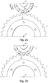
- the pinion 2 is thus mounted so as to be able to move between a disengaged position illustrated in figure 1 in which the pinion 2 is remote from the crown 1, and a meshing position illustrated in figure 2b in which the pinion 2 is in phase with the crown 1 to mesh the latter.
- the cylinder V is equipped with an electromagnetic sensor Cp extending along the body C of the cylinder to detect the magnetic field of a permanent magnet integrated at the end of the rod T forming the piston. To this end, the sensor Cp makes it possible to determine the position of the rod T along the axis Xv.
- the drive device D comprises a Hall effect sensor C1 integral with the structure of the electric motor and in front of which the teeth 1a of the ring 1 move in rotation.
- the detection of the presence of teeth 1a by the sensor C1 makes it possible to determine an angular position of the crown 1 with respect to the axis of rotation X1.
- the drive device D also comprises a Hall effect sensor C2 integral with the rod T of the cylinder V and in front of which the rollers 2a of the pinion 2 travel in rotation.
- the detection of the presence of rollers 2a by the sensor C2 makes it possible to determine an angular position of the pinion 2 with respect to the axis of rotation X2.
- the sensors C1, C2 form means for detecting a difference in angular position between the ring gear 1 and the pinion 2.
- An electronic control unit UC is connected to the servovalve Sv, to the electric motor rotating the pinion 2, to the rod position sensor Cp and to the angular position sensors C1, C2 of the gear elements 1, 2.
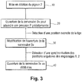
- a first step 10 consists of the control unit UC controlling the electric motor for rotating pinion 2 so as to provide a non-zero speed difference between said pinion 2 and ring gear 1.
- the speed difference is preferably greater than 3 rpm (rotation per minute) to prevent a roller 2a of pinion 2 is permanently opposite a tooth 1a of ring gear 1.
- This state corresponds substantially to the sum in absolute value of the inaccuracies on the measurements and the rotational speed controls of pinion 2 and of ring gear 1. It may also be preferable to limit this speed difference or even the torque delivered by the electric motor to minimize the forces at the moment of contact between the ring gear 1 and the pinion 2. This limitation can in particular be determined as a function of the architecture.
- the flow rate of the servovalve Sv is increased by the control unit UC to reach, in the chamber Ch of the cylinder V, a pressure P sufficient to move the rod T of the cylinder V.
- the pinion 2 moves then at a substantially constant speed towards the meshing position until the control unit UC detects via the position sensor Cp an intermediate position of the rod T.
- the sensor Cp can be a position sensor or a sensor distance allowing the arrival of pinion 2 to be detected in the intermediate position of rod T.
- the control unit UC compares the changes of state of the angular position sensors C1, C2 of the ring gear 1 and of the pinion 2. As soon as the control unit UC observes an appropriate synchronization of the angular positions of the ring gear 1 and of pinion 2, the flow rate of the servovalve is then, during a fourth step 40, increased to a maximum flow rate so as to move as quickly as possible the rod T towards the meshing position so that said rod T travels the remaining distance to bring the pinion 2 into the meshing position before the end of the period during which an engagement without shock is possible.
- a maximum flow rate substantially equal to 10 liters per minute is preferred.
- the appropriate synchronization of the angular positions of the crown 1 and of the pinion 2 corresponds for example to a moment when a tooth 1a of the crown 1 is substantially opposite a hollow formed between two rollers 2a of the pinion 2, or even to a when a roller 2a of the pinion 2 is substantially opposite a hollow formed between two teeth 1a of the crown 1.
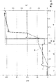
- the figure 4 illustrates the displacement Dp of the rod T of the cylinder V between the disengaged position and the engagement position as well as the evolution of the pressure P inside the chamber Ch of the cylinder V during steps 10, 20, 30, 40.
- the second gear element is a roller pinion
- another type of pinion can be envisaged such as for example a pinion equipped with teeth.
- the axis Xv along which the rod T of the jack V moves may not be orthogonal to the axis of rotation X1 of the ring gear.
- the engagement between the pinion and the crown wheel is here radial, it may very well be axial or tangential (in particular the case of bevel gears).
- jack V is here hydraulic
- the use of a pneumatic jack associated with a solenoid valve is just as possible for an operation similar to the embodiment described.
- the angular position of crown 1 and / or pinion 2 can also be determined using incremental rotary encoders.
- the position sensor Cp of the rod T is electromagnetic
- other types of sensor can be chosen according to the architecture of the drive device and the associated constraints (hydraulic, pneumatic, electromechanical, electrical, optical or optronics ). It is also possible to measure the distance, in particular between the outer diameter of the ring gear and that of the pinion.
Landscapes
- Engineering & Computer Science (AREA)
- General Engineering & Computer Science (AREA)
- Mechanical Engineering (AREA)
- Aviation & Aerospace Engineering (AREA)
- Gear Transmission (AREA)
- Transmission Devices (AREA)
- Hydraulic Clutches, Magnetic Clutches, Fluid Clutches, And Fluid Joints (AREA)
- Indication Of The Valve Opening Or Closing Status (AREA)
Claims (10)
- Eingriffsverfahren zum Eingriff eines ersten Getriebeelements (1) in ein zweites Getriebeelement (2), wobei mindestens das zweite Getriebeelement (2) mit Hilfe eines Aktors (V) beweglich zwischen einer eingerückten Stellung und einer ausgerückten Stellung gelagert ist, wobei das Eingriffsverfahren den Schritt des Antreibens mindestens eines der Getriebeelemente in Drehung umfasst, um einen von Null verschiedenen Drehgeschwindigkeitsunterschied zwischen den genannten Getriebeelementen herzustellen, sowie den Schritt des Steuerns des Aktors (V) um nacheinander:- mindestens das zweite Getriebeelement in die eingerückte Stellung zu bewegen,- wenn eine Zwischenstellung des zweiten Getriebeelements in der Nähe des ersten Getriebeelements erfasst wird, in der das zweite Getriebeelement von dem ersten Getriebeelement ausreichend entfernt bleibt, um jeglichen Kontakt zwischen denselben zu verhindern, die Bewegung des genannten zweiten Getriebeelements zu stoppen,- wenn eine Winkelstellung eines gegenseitigen Eingriffs der genannten Getriebeelemente erfasst wird, in der das zweite Getriebeelement im Wesentlichen in Phase mit dem ersten Getriebeelement ist, um in dieses einzugreifen, das genannte zweite Getriebeelement bis in die eingerückte Stellung zu bewegen.
- Eingriffsverfahren nach Anspruch 1, bei dem der Aktor einen Zylinder (V) umfasst, der eine Stange (T) hat, die von einem Servoventil (Sv) gesteuert wird und die mit dem zweiten Getriebeelement verbunden ist, und bei dem:- eine Erhöhung der Durchflussrate in dem Servoventil (Sv) ein Erreichen eines vorbestimmten Druckes und ein Verschieben der Stange (T) des Zylinders (V) in Richtung der eingerückten Stellung ermöglicht,- ein Positionssensor (Cp) die Erfassung der Zwischenstellung des zweiten Getriebeelements in Bezug auf das erste Getriebeelement ermöglicht, wobei eine Modifikation der Durchflussrate in dem Servoventil (Sv) dann ein Stoppen der Verschiebung (Dp) der Stange (T) des Zylinders (V) ermöglicht,- wobei ein erster Winkelpositionssensor (C1) zur Erfassung der Winkelstellung des ersten Getriebeelementes (1) und ein zweiter Winkelpositionssensor (C2) zur Erfassung der Winkelstellung des zweiten Getriebeelements (2) das Erfassen der Eingriffswinkelstellung der genannten Getriebeelemente ermöglicht, wobei eine Erhöhung der Durchflussrate in dem Servoventil bis zu einer maximalen Durchflussrate dann das Bringen der Stange (T) des Zylinders (V) bis in die eingerückte Stellung ermöglicht.
- Antriebsvorrichtung, umfassend ein erstes Getriebeelement (1), ein zweites Getriebeelement (2), das mit Hilfe eines Aktors (V) zwischen einer in das erste Getriebeelement eingerückten Stellung und einer ausgerückten Stellung beweglich ist, einen Motor, der eines der Getriebeelemente in Drehung antreibt, erste Erfassungsmittel (Cp) zum Erfassen einer Zwischenstellung des zweiten Getriebeelements (2) in Bezug auf das erste Getriebeelement, zweite Erfassungsmittel (C1, C2) zum Erfassen einer Winkelstellungsdifferenz zwischen dem ersten Getriebeelement und dem zweiten Getriebeelement, eine elektronische Steuereinheit (UC), die mit dem Aktor (V), dem Motor, den ersten Erfassungsmitteln (Cp) und den zweiten Erfassungsmitteln verbunden ist, dadurch gekennzeichnet, dass die Steuereinheit (UC) so ausgebildet ist, dass sie das Verfahren nach einem der vorhergehenden Ansprüche durchführt.
- Antriebsvorrichtung nach Anspruch 3, bei der der Aktor (V) einen Zylinder (V) umfasst, der eine Stange (T) hat, die mit dem zweiten Getriebeelement (2) verbunden ist, ein Servoventil (Sv) den Zylinder (V) steuert, die ersten Erfassungsmittel einen Positionssensor (Cp) zum Erfassen der Position der Stange (T) umfassen, und die zweiten Erfassungsmittel einen Winkelpositionssensor (C1) zum Erfassen der Winkelstellung des ersten Getriebeelements (1) und einen Winkelpositionssensor (C2) zum Erfassen der Winkelstellung des zweiten Getriebeelements (2) umfassen.
- Antriebsvorrichtung nach Anspruch 4, bei der der Winkelpositionssensor (C1) des ersten Getriebeelements (1) und der Winkelpositionssensor (C2) des zweiten Getriebeelements (2) Hall-Effekt-Sensoren sind.
- Antriebsvorrichtung nach einem der Ansprüche 4 und 5, bei der der Zylinder (V) ein Hydraulikzylinder ist.
- Antriebsvorrichtung nach einem der Ansprüche 3 bis 6, bei der der Motor ein Elektromotor ist.
- Antriebsvorrichtung nach einem der Ansprüche 3 bis 7, bei der das erste Getriebeelement (1) ein Zahnkranz und das zweite Getriebeelement (2) ein Rollen-Ritzel ist.
- Antriebsvorrichtung nach Anspruch 8, bei der der Zahnkranz (1) fest mit einem Rad (R) verbunden ist.
- Fahrwerk, das mit einer Antriebsvorrichtung nach einem der Ansprüche 3 bis 9 ausgestattet ist.
Applications Claiming Priority (1)
| Application Number | Priority Date | Filing Date | Title |
|---|---|---|---|
| FR1857978A FR3085457B1 (fr) | 2018-09-05 | 2018-09-05 | Procede d'engagement de deux elements engrenage et dispositif d'entrainement mettant en œuvre un tel procede |
Publications (2)
| Publication Number | Publication Date |
|---|---|
| EP3620687A1 EP3620687A1 (de) | 2020-03-11 |
| EP3620687B1 true EP3620687B1 (de) | 2021-05-26 |
Family
ID=63896427
Family Applications (1)
| Application Number | Title | Priority Date | Filing Date |
|---|---|---|---|
| EP19195739.8A Active EP3620687B1 (de) | 2018-09-05 | 2019-09-05 | Verbindungsverfahren von zwei verzahnungselementen und antriebsvorrichtung, bei der dieses verfahren angewandt wird |
Country Status (5)
| Country | Link |
|---|---|
| US (1) | US11231088B2 (de) |
| EP (1) | EP3620687B1 (de) |
| CN (1) | CN110877715B (de) |
| ES (1) | ES2881644T3 (de) |
| FR (1) | FR3085457B1 (de) |
Families Citing this family (1)
| Publication number | Priority date | Publication date | Assignee | Title |
|---|---|---|---|---|
| US11407502B2 (en) * | 2020-02-24 | 2022-08-09 | Safran Landing Systems Canada Inc. | Taxi drive system for aircraft |
Family Cites Families (10)
| Publication number | Priority date | Publication date | Assignee | Title |
|---|---|---|---|---|
| US3807664A (en) * | 1971-09-21 | 1974-04-30 | Nace B | Self-contained aircraft taxiing system |
| WO2002038988A1 (de) * | 2000-11-07 | 2002-05-16 | Luk Lamellen Und Kupplungsbau Beteiligungs Kg | Elektromotorstellglied für getriebe |
| GB0915009D0 (en) | 2009-08-28 | 2009-09-30 | Airbus Operations Ltd | Aircraft landing gear |
| FR2975667B1 (fr) * | 2011-05-27 | 2013-07-12 | Airbus Operations Sas | Dispositif d'interface debrayable entre un systeme de motorisation de roue de train d'atterrissage d'avion et une roue |
| US9188097B2 (en) * | 2013-03-15 | 2015-11-17 | Remy Technologies, Llc | Starter with speed sensor assembly |
| EP2801520B1 (de) * | 2013-05-07 | 2016-03-30 | Airbus Operations GmbH | Antriebssystem für ein hochauftriebssystem eines flugzeuges und verfahren zur erkennung einer fehlausrichtung zwischen einer getriebewelle und einer öffnung in einem antriebssystem für ein hochauftriebssystem eines flugzeugs |
| CN108423161A (zh) | 2013-09-05 | 2018-08-21 | 空中客车营运有限公司 | 用于飞行器的起落架的驱动系统以及飞行器的起落架 |
| GB2524762B (en) * | 2014-04-01 | 2020-06-17 | Airbus Operations Ltd | Drive system for aircraft landing gear |
| GB2524763B (en) * | 2014-04-01 | 2020-06-17 | Airbus Operations Ltd | Drive system for aircraft landing gear |
| GB2528966A (en) * | 2014-08-07 | 2016-02-10 | Airbus Operations Ltd | Landing gear drive system |
-
2018
- 2018-09-05 FR FR1857978A patent/FR3085457B1/fr active Active
-
2019
- 2019-09-04 US US16/560,262 patent/US11231088B2/en active Active
- 2019-09-05 CN CN201910836970.8A patent/CN110877715B/zh active Active
- 2019-09-05 ES ES19195739T patent/ES2881644T3/es active Active
- 2019-09-05 EP EP19195739.8A patent/EP3620687B1/de active Active
Also Published As
| Publication number | Publication date |
|---|---|
| FR3085457A1 (fr) | 2020-03-06 |
| ES2881644T3 (es) | 2021-11-30 |
| FR3085457B1 (fr) | 2021-01-22 |
| CN110877715A (zh) | 2020-03-13 |
| US20200072317A1 (en) | 2020-03-05 |
| US11231088B2 (en) | 2022-01-25 |
| EP3620687A1 (de) | 2020-03-11 |
| CN110877715B (zh) | 2023-06-06 |
Similar Documents
| Publication | Publication Date | Title |
|---|---|---|
| CA3037781C (fr) | Procede d'engagement de deux elements engrenage et dispositif d'entrainement mettant en oeuvre un tel procede | |
| EP3546792B1 (de) | Verfahren zum eingriff zweier zahnräder und antriebsvorrichtung zur durchführung eines derartigen verfahrens | |
| EP3034397B1 (de) | Motorisierungssystem eines rads, das mit einer aufhängung versehen ist | |
| FR2794834A1 (fr) | Procede de mise en oeuvre d'une transmission et transmission convenant a l'application de ce procede | |
| FR3026717A1 (fr) | Atterrisseur d'aeronef. | |
| EP3620687B1 (de) | Verbindungsverfahren von zwei verzahnungselementen und antriebsvorrichtung, bei der dieses verfahren angewandt wird | |
| FR2771173A1 (fr) | Procede de test d'un dispositif d'embrayage automatise | |
| FR3116578A1 (fr) | Dispositif d’entraînement électrique d’un essieu d’un véhicule | |
| EP1767829B1 (de) | Getriebe enthaltend einen mit einem Kraftsensor ausgestatteten Aktuator | |
| EP3087285B1 (de) | Verbesserte scheibenbremse mit einer hydraulisch betätigten feststellbremse und einer verschleisseinstellungseinheit | |
| EP0420738B1 (de) | Gestänge zur Kraftübertragung für Kraftfahrzeuge | |
| EP3424822B1 (de) | Gassteuerungssystem eines luftfahrzeugs | |
| EP3087286B1 (de) | Scheibenbremse mit einer parkbremse mit hydraulischer betätigung | |
| EP3245427B1 (de) | Verfahren zur herstellung eines propelleruntersetzungsgetriebes | |
| EP3043966B1 (de) | Mechanismus zum verriegeln/entriegeln eines drehmomentschlüssels | |
| FR3056160B1 (fr) | Transmission pour vehicule automobile a propulsion electrique | |
| FR2519385A1 (fr) | Ensemble a dispositifs de commande d'un moteur et de reaction | |
| EP4264380B1 (de) | Gerät zur gleichzeitigen messung von kraft und weg, insbesondere für die lagerung von uhrwerkskomponenten | |
| FR2841625A1 (fr) | Procede de mise en oeuvre d'un dispositif de boite de vitesses et dispositif correspondant | |
| EP3087288B1 (de) | Scheibenbremse mit hydraulischer steuerung mit einer feststellbremse mit hydraulischer betätigung | |
| FR2904864A1 (fr) | Dispositif de passage de la marche arriere pour boite de vitesses pilotee | |
| WO2018046827A1 (fr) | Procédé de calcul de positions pour la synchronisation d'une boite de vitesses a double embrayage | |
| EP3087289B1 (de) | Verbesserte scheibenbremse mit einer hydraulisch betätigten feststellbremse | |
| FR3140920A1 (fr) | Procede de pilotage d’une boite de vitesse | |
| FR2823574A1 (fr) | Actionneur commande electriquement |
Legal Events
| Date | Code | Title | Description |
|---|---|---|---|
| PUAI | Public reference made under article 153(3) epc to a published international application that has entered the european phase |
Free format text: ORIGINAL CODE: 0009012 |
|
| STAA | Information on the status of an ep patent application or granted ep patent |
Free format text: STATUS: THE APPLICATION HAS BEEN PUBLISHED |
|
| AK | Designated contracting states |
Kind code of ref document: A1 Designated state(s): AL AT BE BG CH CY CZ DE DK EE ES FI FR GB GR HR HU IE IS IT LI LT LU LV MC MK MT NL NO PL PT RO RS SE SI SK SM TR |
|
| AX | Request for extension of the european patent |
Extension state: BA ME |
|
| STAA | Information on the status of an ep patent application or granted ep patent |
Free format text: STATUS: REQUEST FOR EXAMINATION WAS MADE |
|
| 17P | Request for examination filed |
Effective date: 20200903 |
|
| RBV | Designated contracting states (corrected) |
Designated state(s): AL AT BE BG CH CY CZ DE DK EE ES FI FR GB GR HR HU IE IS IT LI LT LU LV MC MK MT NL NO PL PT RO RS SE SI SK SM TR |
|
| GRAP | Despatch of communication of intention to grant a patent |
Free format text: ORIGINAL CODE: EPIDOSNIGR1 |
|
| STAA | Information on the status of an ep patent application or granted ep patent |
Free format text: STATUS: GRANT OF PATENT IS INTENDED |
|
| RIC1 | Information provided on ipc code assigned before grant |
Ipc: F16H 61/28 20060101AFI20201106BHEP Ipc: B64C 25/40 20060101ALI20201106BHEP |
|
| INTG | Intention to grant announced |
Effective date: 20201201 |
|
| GRAS | Grant fee paid |
Free format text: ORIGINAL CODE: EPIDOSNIGR3 |
|
| GRAA | (expected) grant |
Free format text: ORIGINAL CODE: 0009210 |
|
| STAA | Information on the status of an ep patent application or granted ep patent |
Free format text: STATUS: THE PATENT HAS BEEN GRANTED |
|
| AK | Designated contracting states |
Kind code of ref document: B1 Designated state(s): AL AT BE BG CH CY CZ DE DK EE ES FI FR GB GR HR HU IE IS IT LI LT LU LV MC MK MT NL NO PL PT RO RS SE SI SK SM TR |
|
| REG | Reference to a national code |
Ref country code: GB Ref legal event code: FG4D Free format text: NOT ENGLISH |
|
| REG | Reference to a national code |
Ref country code: CH Ref legal event code: EP |
|
| REG | Reference to a national code |
Ref country code: DE Ref legal event code: R096 Ref document number: 602019004871 Country of ref document: DE |
|
| REG | Reference to a national code |
Ref country code: AT Ref legal event code: REF Ref document number: 1396552 Country of ref document: AT Kind code of ref document: T Effective date: 20210615 |
|
| REG | Reference to a national code |
Ref country code: IE Ref legal event code: FG4D Free format text: LANGUAGE OF EP DOCUMENT: FRENCH |
|
| REG | Reference to a national code |
Ref country code: LT Ref legal event code: MG9D |
|
| REG | Reference to a national code |
Ref country code: AT Ref legal event code: MK05 Ref document number: 1396552 Country of ref document: AT Kind code of ref document: T Effective date: 20210526 |
|
| PG25 | Lapsed in a contracting state [announced via postgrant information from national office to epo] |
Ref country code: LT Free format text: LAPSE BECAUSE OF FAILURE TO SUBMIT A TRANSLATION OF THE DESCRIPTION OR TO PAY THE FEE WITHIN THE PRESCRIBED TIME-LIMIT Effective date: 20210526 Ref country code: HR Free format text: LAPSE BECAUSE OF FAILURE TO SUBMIT A TRANSLATION OF THE DESCRIPTION OR TO PAY THE FEE WITHIN THE PRESCRIBED TIME-LIMIT Effective date: 20210526 Ref country code: FI Free format text: LAPSE BECAUSE OF FAILURE TO SUBMIT A TRANSLATION OF THE DESCRIPTION OR TO PAY THE FEE WITHIN THE PRESCRIBED TIME-LIMIT Effective date: 20210526 Ref country code: AT Free format text: LAPSE BECAUSE OF FAILURE TO SUBMIT A TRANSLATION OF THE DESCRIPTION OR TO PAY THE FEE WITHIN THE PRESCRIBED TIME-LIMIT Effective date: 20210526 Ref country code: BG Free format text: LAPSE BECAUSE OF FAILURE TO SUBMIT A TRANSLATION OF THE DESCRIPTION OR TO PAY THE FEE WITHIN THE PRESCRIBED TIME-LIMIT Effective date: 20210826 |
|
| REG | Reference to a national code |
Ref country code: NL Ref legal event code: MP Effective date: 20210526 |
|
| PG25 | Lapsed in a contracting state [announced via postgrant information from national office to epo] |
Ref country code: SE Free format text: LAPSE BECAUSE OF FAILURE TO SUBMIT A TRANSLATION OF THE DESCRIPTION OR TO PAY THE FEE WITHIN THE PRESCRIBED TIME-LIMIT Effective date: 20210526 Ref country code: PT Free format text: LAPSE BECAUSE OF FAILURE TO SUBMIT A TRANSLATION OF THE DESCRIPTION OR TO PAY THE FEE WITHIN THE PRESCRIBED TIME-LIMIT Effective date: 20210927 Ref country code: RS Free format text: LAPSE BECAUSE OF FAILURE TO SUBMIT A TRANSLATION OF THE DESCRIPTION OR TO PAY THE FEE WITHIN THE PRESCRIBED TIME-LIMIT Effective date: 20210526 Ref country code: PL Free format text: LAPSE BECAUSE OF FAILURE TO SUBMIT A TRANSLATION OF THE DESCRIPTION OR TO PAY THE FEE WITHIN THE PRESCRIBED TIME-LIMIT Effective date: 20210526 Ref country code: NO Free format text: LAPSE BECAUSE OF FAILURE TO SUBMIT A TRANSLATION OF THE DESCRIPTION OR TO PAY THE FEE WITHIN THE PRESCRIBED TIME-LIMIT Effective date: 20210826 Ref country code: LV Free format text: LAPSE BECAUSE OF FAILURE TO SUBMIT A TRANSLATION OF THE DESCRIPTION OR TO PAY THE FEE WITHIN THE PRESCRIBED TIME-LIMIT Effective date: 20210526 Ref country code: GR Free format text: LAPSE BECAUSE OF FAILURE TO SUBMIT A TRANSLATION OF THE DESCRIPTION OR TO PAY THE FEE WITHIN THE PRESCRIBED TIME-LIMIT Effective date: 20210827 Ref country code: IS Free format text: LAPSE BECAUSE OF FAILURE TO SUBMIT A TRANSLATION OF THE DESCRIPTION OR TO PAY THE FEE WITHIN THE PRESCRIBED TIME-LIMIT Effective date: 20210926 |
|
| REG | Reference to a national code |
Ref country code: ES Ref legal event code: FG2A Ref document number: 2881644 Country of ref document: ES Kind code of ref document: T3 Effective date: 20211130 |
|
| PG25 | Lapsed in a contracting state [announced via postgrant information from national office to epo] |
Ref country code: NL Free format text: LAPSE BECAUSE OF FAILURE TO SUBMIT A TRANSLATION OF THE DESCRIPTION OR TO PAY THE FEE WITHIN THE PRESCRIBED TIME-LIMIT Effective date: 20210526 |
|
| PG25 | Lapsed in a contracting state [announced via postgrant information from national office to epo] |
Ref country code: SM Free format text: LAPSE BECAUSE OF FAILURE TO SUBMIT A TRANSLATION OF THE DESCRIPTION OR TO PAY THE FEE WITHIN THE PRESCRIBED TIME-LIMIT Effective date: 20210526 Ref country code: RO Free format text: LAPSE BECAUSE OF FAILURE TO SUBMIT A TRANSLATION OF THE DESCRIPTION OR TO PAY THE FEE WITHIN THE PRESCRIBED TIME-LIMIT Effective date: 20210526 Ref country code: CZ Free format text: LAPSE BECAUSE OF FAILURE TO SUBMIT A TRANSLATION OF THE DESCRIPTION OR TO PAY THE FEE WITHIN THE PRESCRIBED TIME-LIMIT Effective date: 20210526 Ref country code: DK Free format text: LAPSE BECAUSE OF FAILURE TO SUBMIT A TRANSLATION OF THE DESCRIPTION OR TO PAY THE FEE WITHIN THE PRESCRIBED TIME-LIMIT Effective date: 20210526 Ref country code: EE Free format text: LAPSE BECAUSE OF FAILURE TO SUBMIT A TRANSLATION OF THE DESCRIPTION OR TO PAY THE FEE WITHIN THE PRESCRIBED TIME-LIMIT Effective date: 20210526 Ref country code: SK Free format text: LAPSE BECAUSE OF FAILURE TO SUBMIT A TRANSLATION OF THE DESCRIPTION OR TO PAY THE FEE WITHIN THE PRESCRIBED TIME-LIMIT Effective date: 20210526 |
|
| REG | Reference to a national code |
Ref country code: DE Ref legal event code: R097 Ref document number: 602019004871 Country of ref document: DE |
|
| PLBE | No opposition filed within time limit |
Free format text: ORIGINAL CODE: 0009261 |
|
| STAA | Information on the status of an ep patent application or granted ep patent |
Free format text: STATUS: NO OPPOSITION FILED WITHIN TIME LIMIT |
|
| 26N | No opposition filed |
Effective date: 20220301 |
|
| REG | Reference to a national code |
Ref country code: BE Ref legal event code: MM Effective date: 20210930 |
|
| PG25 | Lapsed in a contracting state [announced via postgrant information from national office to epo] |
Ref country code: IS Free format text: LAPSE BECAUSE OF FAILURE TO SUBMIT A TRANSLATION OF THE DESCRIPTION OR TO PAY THE FEE WITHIN THE PRESCRIBED TIME-LIMIT Effective date: 20210926 Ref country code: MC Free format text: LAPSE BECAUSE OF FAILURE TO SUBMIT A TRANSLATION OF THE DESCRIPTION OR TO PAY THE FEE WITHIN THE PRESCRIBED TIME-LIMIT Effective date: 20210526 Ref country code: AL Free format text: LAPSE BECAUSE OF FAILURE TO SUBMIT A TRANSLATION OF THE DESCRIPTION OR TO PAY THE FEE WITHIN THE PRESCRIBED TIME-LIMIT Effective date: 20210526 |
|
| PG25 | Lapsed in a contracting state [announced via postgrant information from national office to epo] |
Ref country code: LU Free format text: LAPSE BECAUSE OF NON-PAYMENT OF DUE FEES Effective date: 20210905 Ref country code: IT Free format text: LAPSE BECAUSE OF FAILURE TO SUBMIT A TRANSLATION OF THE DESCRIPTION OR TO PAY THE FEE WITHIN THE PRESCRIBED TIME-LIMIT Effective date: 20210526 Ref country code: IE Free format text: LAPSE BECAUSE OF NON-PAYMENT OF DUE FEES Effective date: 20210905 Ref country code: BE Free format text: LAPSE BECAUSE OF NON-PAYMENT OF DUE FEES Effective date: 20210930 |
|
| REG | Reference to a national code |
Ref country code: CH Ref legal event code: PL |
|
| PG25 | Lapsed in a contracting state [announced via postgrant information from national office to epo] |
Ref country code: CY Free format text: LAPSE BECAUSE OF FAILURE TO SUBMIT A TRANSLATION OF THE DESCRIPTION OR TO PAY THE FEE WITHIN THE PRESCRIBED TIME-LIMIT Effective date: 20210526 |
|
| PG25 | Lapsed in a contracting state [announced via postgrant information from national office to epo] |
Ref country code: LI Free format text: LAPSE BECAUSE OF NON-PAYMENT OF DUE FEES Effective date: 20220930 Ref country code: HU Free format text: LAPSE BECAUSE OF FAILURE TO SUBMIT A TRANSLATION OF THE DESCRIPTION OR TO PAY THE FEE WITHIN THE PRESCRIBED TIME-LIMIT; INVALID AB INITIO Effective date: 20190905 Ref country code: CH Free format text: LAPSE BECAUSE OF NON-PAYMENT OF DUE FEES Effective date: 20220930 |
|
| PG25 | Lapsed in a contracting state [announced via postgrant information from national office to epo] |
Ref country code: MK Free format text: LAPSE BECAUSE OF FAILURE TO SUBMIT A TRANSLATION OF THE DESCRIPTION OR TO PAY THE FEE WITHIN THE PRESCRIBED TIME-LIMIT Effective date: 20210526 |
|
| PG25 | Lapsed in a contracting state [announced via postgrant information from national office to epo] |
Ref country code: MT Free format text: LAPSE BECAUSE OF FAILURE TO SUBMIT A TRANSLATION OF THE DESCRIPTION OR TO PAY THE FEE WITHIN THE PRESCRIBED TIME-LIMIT Effective date: 20210526 |
|
| PGFP | Annual fee paid to national office [announced via postgrant information from national office to epo] |
Ref country code: DE Payment date: 20250919 Year of fee payment: 7 |
|
| PGFP | Annual fee paid to national office [announced via postgrant information from national office to epo] |
Ref country code: GB Payment date: 20250923 Year of fee payment: 7 |
|
| PGFP | Annual fee paid to national office [announced via postgrant information from national office to epo] |
Ref country code: FR Payment date: 20250923 Year of fee payment: 7 |
|
| PG25 | Lapsed in a contracting state [announced via postgrant information from national office to epo] |
Ref country code: TR Free format text: LAPSE BECAUSE OF FAILURE TO SUBMIT A TRANSLATION OF THE DESCRIPTION OR TO PAY THE FEE WITHIN THE PRESCRIBED TIME-LIMIT Effective date: 20210526 |
|
| PGFP | Annual fee paid to national office [announced via postgrant information from national office to epo] |
Ref country code: ES Payment date: 20251020 Year of fee payment: 7 |