EP3620738A1 - Kühlboxstruktur mit teilweise eingebauten kühlboxpanellen und installationsverfahren dafür - Google Patents
Kühlboxstruktur mit teilweise eingebauten kühlboxpanellen und installationsverfahren dafür Download PDFInfo
- Publication number
- EP3620738A1 EP3620738A1 EP17908663.2A EP17908663A EP3620738A1 EP 3620738 A1 EP3620738 A1 EP 3620738A1 EP 17908663 A EP17908663 A EP 17908663A EP 3620738 A1 EP3620738 A1 EP 3620738A1
- Authority
- EP
- European Patent Office
- Prior art keywords
- cold box
- support frame
- plate
- heat exchanger
- panels
- Prior art date
- Legal status (The legal status is an assumption and is not a legal conclusion. Google has not performed a legal analysis and makes no representation as to the accuracy of the status listed.)
- Withdrawn
Links
- 238000009434 installation Methods 0.000 title claims abstract description 13
- 238000000034 method Methods 0.000 title claims abstract description 12
- 229910000975 Carbon steel Inorganic materials 0.000 claims description 9
- 239000010962 carbon steel Substances 0.000 claims description 9
- 235000019362 perlite Nutrition 0.000 claims description 7
- 239000010451 perlite Substances 0.000 claims description 7
- 239000004576 sand Substances 0.000 claims description 7
- IJGRMHOSHXDMSA-UHFFFAOYSA-N Atomic nitrogen Chemical compound N#N IJGRMHOSHXDMSA-UHFFFAOYSA-N 0.000 claims description 6
- 239000010935 stainless steel Substances 0.000 claims description 5
- 229910001220 stainless steel Inorganic materials 0.000 claims description 5
- 229910052757 nitrogen Inorganic materials 0.000 claims description 3
- 238000003466 welding Methods 0.000 claims description 3
- XAGFODPZIPBFFR-UHFFFAOYSA-N aluminium Chemical compound [Al] XAGFODPZIPBFFR-UHFFFAOYSA-N 0.000 abstract description 5
- 229910052782 aluminium Inorganic materials 0.000 abstract description 5
- 238000000926 separation method Methods 0.000 description 9
- 229910000838 Al alloy Inorganic materials 0.000 description 2
- 238000005219 brazing Methods 0.000 description 2
- 239000000463 material Substances 0.000 description 2
- 238000001816 cooling Methods 0.000 description 1
- 238000010438 heat treatment Methods 0.000 description 1
- 238000009413 insulation Methods 0.000 description 1
- 238000012423 maintenance Methods 0.000 description 1
- 238000012986 modification Methods 0.000 description 1
- 230000004048 modification Effects 0.000 description 1
- 238000005192 partition Methods 0.000 description 1
- 230000008092 positive effect Effects 0.000 description 1
- 238000009417 prefabrication Methods 0.000 description 1
- 238000005057 refrigeration Methods 0.000 description 1
Images


Classifications
-
- F—MECHANICAL ENGINEERING; LIGHTING; HEATING; WEAPONS; BLASTING
- F25—REFRIGERATION OR COOLING; COMBINED HEATING AND REFRIGERATION SYSTEMS; HEAT PUMP SYSTEMS; MANUFACTURE OR STORAGE OF ICE; LIQUEFACTION SOLIDIFICATION OF GASES
- F25J—LIQUEFACTION, SOLIDIFICATION OR SEPARATION OF GASES OR GASEOUS OR LIQUEFIED GASEOUS MIXTURES BY PRESSURE AND COLD TREATMENT OR BY BRINGING THEM INTO THE SUPERCRITICAL STATE
- F25J3/00—Processes or apparatus for separating the constituents of gaseous or liquefied gaseous mixtures involving the use of liquefaction or solidification
- F25J3/02—Processes or apparatus for separating the constituents of gaseous or liquefied gaseous mixtures involving the use of liquefaction or solidification by rectification, i.e. by continuous interchange of heat and material between a vapour stream and a liquid stream
- F25J3/04—Processes or apparatus for separating the constituents of gaseous or liquefied gaseous mixtures involving the use of liquefaction or solidification by rectification, i.e. by continuous interchange of heat and material between a vapour stream and a liquid stream for air
- F25J3/04763—Start-up or control of the process; Details of the apparatus used
- F25J3/04866—Construction and layout of air fractionation equipments, e.g. valves, machines
- F25J3/04945—Details of internal structure; insulation and housing of the cold box
-
- E—FIXED CONSTRUCTIONS
- E04—BUILDING
- E04H—BUILDINGS OR LIKE STRUCTURES FOR PARTICULAR PURPOSES; SWIMMING OR SPLASH BATHS OR POOLS; MASTS; FENCING; TENTS OR CANOPIES, IN GENERAL
- E04H5/00—Buildings or groups of buildings for industrial or agricultural purposes
- E04H5/10—Buildings forming part of cooling plants
-
- F—MECHANICAL ENGINEERING; LIGHTING; HEATING; WEAPONS; BLASTING
- F25—REFRIGERATION OR COOLING; COMBINED HEATING AND REFRIGERATION SYSTEMS; HEAT PUMP SYSTEMS; MANUFACTURE OR STORAGE OF ICE; LIQUEFACTION SOLIDIFICATION OF GASES
- F25D—REFRIGERATORS; COLD ROOMS; ICE-BOXES; COOLING OR FREEZING APPARATUS NOT OTHERWISE PROVIDED FOR
- F25D3/00—Devices using other cold materials; Devices using cold-storage bodies
- F25D3/10—Devices using other cold materials; Devices using cold-storage bodies using liquefied gases, e.g. liquid air
- F25D3/102—Stationary cabinets
-
- F—MECHANICAL ENGINEERING; LIGHTING; HEATING; WEAPONS; BLASTING
- F25—REFRIGERATION OR COOLING; COMBINED HEATING AND REFRIGERATION SYSTEMS; HEAT PUMP SYSTEMS; MANUFACTURE OR STORAGE OF ICE; LIQUEFACTION SOLIDIFICATION OF GASES
- F25J—LIQUEFACTION, SOLIDIFICATION OR SEPARATION OF GASES OR GASEOUS OR LIQUEFIED GASEOUS MIXTURES BY PRESSURE AND COLD TREATMENT OR BY BRINGING THEM INTO THE SUPERCRITICAL STATE
- F25J3/00—Processes or apparatus for separating the constituents of gaseous or liquefied gaseous mixtures involving the use of liquefaction or solidification
- F25J3/02—Processes or apparatus for separating the constituents of gaseous or liquefied gaseous mixtures involving the use of liquefaction or solidification by rectification, i.e. by continuous interchange of heat and material between a vapour stream and a liquid stream
- F25J3/04—Processes or apparatus for separating the constituents of gaseous or liquefied gaseous mixtures involving the use of liquefaction or solidification by rectification, i.e. by continuous interchange of heat and material between a vapour stream and a liquid stream for air
- F25J3/04763—Start-up or control of the process; Details of the apparatus used
- F25J3/04769—Operation, control and regulation of the process; Instrumentation within the process
- F25J3/04854—Safety aspects of operation
-
- F—MECHANICAL ENGINEERING; LIGHTING; HEATING; WEAPONS; BLASTING
- F28—HEAT EXCHANGE IN GENERAL
- F28F—DETAILS OF HEAT-EXCHANGE AND HEAT-TRANSFER APPARATUS, OF GENERAL APPLICATION
- F28F3/00—Plate-like or laminated elements; Assemblies of plate-like or laminated elements
- F28F3/02—Elements or assemblies thereof with means for increasing heat-transfer area, e.g. with fins, with recesses, with corrugations
Definitions
- the present invention relates to a cold box structure for a plate-fin heat exchanger and an installation method therefor, which are particularly suitable for a high-pressure aluminum plate-fin heat exchanger.
- the plate-fin heat exchanger has the characteristics of compact structure, light weight, high heat transfer efficiency, etc., and so is widely used in industrial sectors such as refrigeration, petrochemical, air separation, aerospace, power machinery and superconducting, and is generally recognized as one of the new efficient heat exchangers. Due to the low-temperature ductility and good tensile properties of aluminum alloy, plate-fin heat exchangers made of aluminum alloy are particularly suitable for low-temperature and ultra-low-temperature applications, and are also widely used in air separation processes in modern industries. At present, almost all the heat exchangers of air separation apparatuses use plate-fin heat exchangers. Due to operating at a temperature below -150°C, the air separation apparatus needs to be placed inside a cold box, and the cold box is filled with perlite sand to provide heat insulation.
- the cold box is in the shape of a rectangular hexahedron, comprising a base, a cold box support frame, four cold box panels and a cold box top plate.
- the cold box panels are welded to the outer side the cold box support frame.
- the cold box can be made of carbon steel or stainless steel, but due to the high price of stainless steel, carbon steel is usually used in practice. However, the carbon steel material is prone to brittle fracture at low temperatures. In the process of air separation, if leakage occurs at a plate-fin heat exchanger and low-temperature steam is ejected, the perlite sand inside the cold box becomes damp and hardened, and the cold box panels or the cold box support frame of carbon steel is easily damaged. Failure to timely discover leakage may result in other serious consequences.
- the cold box panels are placed outside the cold box support frame structure.
- cryogenic steam is ejected if leakage occurs at the plate-fin heat exchanger. If the leaked steam is directly ejected to the cold box support frame, since the cold box panels are located outside the cold box support frame and shield the cold box support frame, the damage caused by the leakage is not easily discovered in a timely manner, which may result in the failure to timely discover leakage in the plate-fin heat exchanger. This is not conducive to the safe operation of air separation systems, resulting in degraded quality of air separation products, which also may cause serious safety accidents; in addition, the repair work for the damaged cold box support frame is huge and the cost is high.
- the present invention provides a cold box structure with cold box panels partly built-in, which is applicable to a plate-fin heat exchanger, and in particular to a high-pressure aluminum plate-fin heat exchanger for use in an air separation process.
- the cold box of a carbon steel material in the present invention is especially applicable to brazed aluminum plate-fin heat exchangers with the working pressure higher than 20 bar. Since leakage easily occurs on the sides of the high-pressure plate-fin heat exchanger where seals are located, and the temperature at the cold end of the heat exchanger is -196°C, cryogenic steam ejected due to leakage seriously damages the carbon steel structure, and brittle fracture, etc. may occur.
- cold box panels facing sides of the plate-fin heat exchanger where the seals are located are placed inside the cold box support frame, so that the leakage can be timely discovered from the frost and icing conditions of the cold box panels upon occurring, which has the function of protecting the cold box support frame.
- a cold box structure comprising a base, a cold box support frame, four cold box panels and a cold box top plate, a plate-fin heat exchanger being fixed inside the cold box, wherein the cold box panels facing sides of the plate-fin heat exchanger where seals are located are placed inside the cold box support frame, and perlite sand is filled between the cold box and the plate-fin heat exchanger.
- the cold box support frame, the cold box panels, and the cold box top plate may be made of carbon steel or stainless steel.
- the cold box panels facing sides of the plate-fin heat exchanger where lateral plates are located are placed outside the cold box support frame, and may also be placed inside the cold box support frame.
- An installation method for the cold box structure comprises the steps of:
- step 2) of the installation method the cold box panels facing the seals of the plate-fin heat exchanger are installed in advance inside the cold box support frame, or are installed on-site inside the cold box support frame, depending on the on-site installation size.
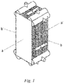
- Fig. 1 is a schematic view of a plate-fin heat exchanger, wherein the sides on which seals of the heat exchanger are located are faces b, b', and the sides on which lateral plates are located are faces a, a'.
- a plate heat exchanger (in particular a brazed aluminum plate heat exchanger) has a heat exchange portion inside which a plurality of heat exchange passages are disposed.
- the heat exchange passages are formed by alternately stacking partition plates and profiled plates (for example, ribbed plates or corrugated plates, finned plates) or distribution devices, and the heat exchange portion is formed by heating and brazing the stack in a suitable brazing furnace. Under high pressure, leakage easily occurs at the brazed joint, that is, leakage easily occurs at the faces b, b' on which the seals of the plate-fin heat exchanger are located.
- Fig. 2 shows a schematic view of a cold box support frame 2, the four sides of which are A, A', B, B', respectively.
- the oblique line areas in the figure represent the interior of the cold box support frame on the side A' and the interior of the cold box support frame on the side B', respectively, and 1 represents a base.
- the sides B, B' of the cold box frame are opposite the sides of the plate-fin heat exchanger where seals are located, and sides A, A' are opposite the sides of the plate-fin heat exchanger where cover plates are located (the plate-fin heat exchanger is not shown in the figure).
- the cold box panels 3b, 3b' are installed inside the cold box support frames on the sides B and B', and the cold box panels 3a, 3a' are installed outside or inside the cold box support frames on the sides A and A'.
- Fig. 3 is a first embodiment of the present invention, comprising a base 1, a cold box support frame 2, a cold box top plate 4, and four cold box panels 3a, 3a', 3b, 3b', wherein the oblique line areas in the figure respectively represent the cold box panel 3a and the cold box panel 3b (3a', 3b' are not visible in the figure).
- the cold box panels 3b, 3b' are placed inside the cold box support frame 2, and the cold box panels 3a, 3a' are placed outside the cold box support frame 2.
- Faces a and a' of the plate-fin heat exchanger are symmetrical faces of the plate-fin heat exchanger, and faces b and b' are further symmetrical faces of the plate-fin heat exchanger.
- the sides A and A' of the cold box frame are symmetrical to each other, and the sides B and B' are symmetrical to each other.
- the cold box panels 3a and 3a' are symmetrical to each other, and 3b and 3b' are symmetrical to each other.
- the interior of the cold box support frame refers to the side of the cold box support frame facing the heat exchanger; and the exterior of the cold box support frame refers to the side of the cold box support frame facing the outside air.
- the cold box panels 3a, 3a', 3b, 3b' refer to the panels on four sides of the cold box
- the cold box top plate 4 refers to the panel located at the top of the cold box
- the base 1 refers to a structure located at the bottom of the cold box for supporting the cold box
- the cold box support frame 2 refers to a structure that supports the cold box panels to fix the cold box panels.
- the cold box panels 3b, 3b' facing the faces b, b' of the plate-fin heat exchanger are located inside the cold box support frames on the sides B, B'. Since leakage easily occurs at the faces b, b' of the plate-fin heat exchanger, the cold box panels 3b, 3b' facing the faces b, b' are built inside the cold box support frame, which can prevent leaked steam from being directly ejected to the cold box support frame, thereby having a protection function. In addition, the leakage can be discovered timely. If the cold box panels 3b, 3b' are placed outside the support frame, and if the cryogenic steam ejected due to leakage is directly ejected to the support frame, the leakage is not easily discovered due to the shielding of the cold box panels.
- the cold box panels 3a, 3a' facing the faces a, a' of the plate-fin heat exchanger are located outside the cold box support frame on the sides A, A'. Since leakage doesn't easily occur at the faces a, a' of the plate-fin heat exchanger, in order to reduce installation difficulty, the cold box panels 3a, 3a' are installed outside the cold box support frame.
- Fig. 4 is a second embodiment of the present invention, comprising a base 1, a cold box support frame 2, a cold box top plate 4, and four cold box panels 3a, 3a', 3b, 3b', wherein the oblique line areas in the figure respectively represent the cold box panel 3a and the cold box panel 3b (3a', 3b' are not visible in the figure).
- the four cold box panels 3a, 3a', 3b, 3b' are all placed inside the cold box support frame 2.
- the cold box structure comprises the cold box panels 3a, 3a', 3b, 3b' placed inside the cold box support frame, wherein the cold box panels 3a, 3a' are placed inside the cold box support frame on sides A, A', and the cold box panels 3b, 3b' are placed inside the cold box support frame on sides B, B'.
- the cold box support frame and the cold box panels are made of carbon steel or stainless steel.
- step 2) of the foregoing installation method when the installation size is limited, the cold box panels 3b, 3b' facing the seals of the plate-fin heat exchanger may be installed in advance inside the cold box support frame on the sides B, B'; and if the installation size is not limited on-site, the cold box panels 3b, 3b' may be installed on-site inside the cold box support frame on the sides B, B'.
- equipment components or attachments such as pipes, cable shafts, valves or observation facilities and supports, may be installed during factory prefabrication.
- the present invention is applicable not only to rectangular parallelepiped cold boxes but also to cylindrical cold boxes.
- the present invention is also not limited to be applicable to plate-fin heat exchangers, but to all cases where leakage can be judged by means of the surface of the cold box, or where the cold box support frame needs to be protected.
Landscapes
- Engineering & Computer Science (AREA)
- Physics & Mathematics (AREA)
- Mechanical Engineering (AREA)
- Thermal Sciences (AREA)
- General Engineering & Computer Science (AREA)
- Architecture (AREA)
- Civil Engineering (AREA)
- Structural Engineering (AREA)
- Chemical & Material Sciences (AREA)
- Combustion & Propulsion (AREA)
- Heat-Exchange Devices With Radiators And Conduit Assemblies (AREA)
Applications Claiming Priority (1)
| Application Number | Priority Date | Filing Date | Title |
|---|---|---|---|
| PCT/CN2017/082891 WO2018201339A1 (zh) | 2017-05-03 | 2017-05-03 | 冷箱面板部分内置的冷箱结构及其安装方法 |
Publications (2)
| Publication Number | Publication Date |
|---|---|
| EP3620738A1 true EP3620738A1 (de) | 2020-03-11 |
| EP3620738A4 EP3620738A4 (de) | 2020-11-25 |
Family
ID=64015750
Family Applications (1)
| Application Number | Title | Priority Date | Filing Date |
|---|---|---|---|
| EP17908663.2A Withdrawn EP3620738A4 (de) | 2017-05-03 | 2017-05-03 | Kühlboxstruktur mit teilweise eingebauten kühlboxpanellen und installationsverfahren dafür |
Country Status (4)
| Country | Link |
|---|---|
| US (1) | US20200056840A1 (de) |
| EP (1) | EP3620738A4 (de) |
| CN (1) | CN110612422A (de) |
| WO (1) | WO2018201339A1 (de) |
Families Citing this family (2)
| Publication number | Priority date | Publication date | Assignee | Title |
|---|---|---|---|---|
| CN109455418A (zh) * | 2018-12-17 | 2019-03-12 | 乔治洛德方法研究和开发液化空气有限公司 | 一种冷箱钢结构及预制和运输所述冷箱钢结构的方法 |
| CN115371358A (zh) * | 2022-07-21 | 2022-11-22 | 杭州福斯达深冷装备股份有限公司 | 空气分离装置及其冷箱组件 |
Family Cites Families (9)
| Publication number | Priority date | Publication date | Assignee | Title |
|---|---|---|---|---|
| FR2799822B1 (fr) * | 1999-10-18 | 2002-03-29 | Air Liquide | Boite froide, installation de distillation d'air et procede de construction correspondants |
| DE10229663A1 (de) * | 2002-07-02 | 2004-01-22 | Linde Ag | Coldboxblechmantel |
| WO2008014899A1 (de) * | 2006-08-04 | 2008-02-07 | Linde Aktiengesellschaft | Verfahren zur herstellung einer coldbox, coldbox und coldbox- paneel |
| US9051749B2 (en) * | 2008-12-10 | 2015-06-09 | Air Liquide Global E&C Solutions US, Inc. | Hybrid method of erecting a cold box using prefabricated and field erected components |
| US8727159B2 (en) * | 2011-04-12 | 2014-05-20 | Conocophillips Company | Cold box design providing secondary containment |
| CN202133229U (zh) * | 2011-06-07 | 2012-02-01 | 上海启元气体发展有限公司 | 一种大型空气分离设备的冷箱 |
| FR2995673B1 (fr) * | 2012-09-19 | 2018-08-10 | L'air Liquide,Societe Anonyme Pour L'etude Et L'exploitation Des Procedes Georges Claude | Echangeur de chaleur et ensemble d'echangeurs destine a la distillation d'air comprenant de tels echangeurs de chaleur |
| DE102013012606B4 (de) * | 2013-02-19 | 2015-08-06 | CRYOTEC Anlagenbau GmbH | Modulare verfahrenstechnische Anlage, insbesondere Luftzerlegungsanlage mit einer Vielzahl von Anlagenkomponenten |
| FR3017443B1 (fr) * | 2014-02-11 | 2016-09-02 | Air Liquide | Enceinte isolee et procede de balayage d'une telle enceinte |
-
2017
- 2017-05-03 EP EP17908663.2A patent/EP3620738A4/de not_active Withdrawn
- 2017-05-03 WO PCT/CN2017/082891 patent/WO2018201339A1/zh not_active Ceased
- 2017-05-03 CN CN201780090098.6A patent/CN110612422A/zh active Pending
- 2017-05-03 US US16/610,205 patent/US20200056840A1/en not_active Abandoned
Also Published As
| Publication number | Publication date |
|---|---|
| WO2018201339A1 (zh) | 2018-11-08 |
| US20200056840A1 (en) | 2020-02-20 |
| EP3620738A4 (de) | 2020-11-25 |
| CN110612422A (zh) | 2019-12-24 |
Similar Documents
| Publication | Publication Date | Title |
|---|---|---|
| WO2017034117A1 (ko) | 앵커 스트립이 제거된 액화가스 화물창의 인슐레이션 구조, 그 인슐레이션 구조를 구비하는 화물창, 및 그 화물창을 구비하는 액화가스 운반선 | |
| EP3620738A1 (de) | Kühlboxstruktur mit teilweise eingebauten kühlboxpanellen und installationsverfahren dafür | |
| WO2025241713A1 (zh) | 储能柜 | |
| KR101794359B1 (ko) | 액화천연가스 운반선의 탱크 내벽 구조 | |
| Monneret et al. | ITER cryoplant status and economics of the LHe plants | |
| CN220254986U (zh) | 一种浸没式相变液冷服务器机柜 | |
| CN1304810C (zh) | 采用低热漏柔性连接结构的高真空低温恒温器 | |
| RU2724088C1 (ru) | Теплообменник в сборе и способ его сборки | |
| JP5385193B2 (ja) | 製氷安定方法及び氷製造装置 | |
| JP2011208890A (ja) | 製氷安定方法及び氷製造装置 | |
| JP5385194B2 (ja) | 製氷安定方法及び氷製造装置 | |
| CN121498458A (zh) | 一种管路防护装置及包含该装置的板翅式换热器冷箱 | |
| US20240310114A1 (en) | Liquefactor and method for liquefying a gas | |
| KR102499836B1 (ko) | 에어 스페이서 및 그의 시공방법 | |
| CN224150429U (zh) | 一种耐高温耐腐蚀高密封性的波纹膨胀节 | |
| KR102488376B1 (ko) | 단열성을 개선한 플랜트 배관 구조체 | |
| CN220288303U (zh) | 一种消除侧梁线性膨胀破坏的芯体 | |
| CN220418185U (zh) | 一种组合型节能换热装置 | |
| CN223690567U (zh) | 一种供冷管道的连接结构 | |
| CN205373409U (zh) | 一种具有模块衬里的加热炉 | |
| CN216558393U (zh) | 一种冷却塔盘管防冻装置 | |
| Quimby et al. | VJR/VJRR design, construction, installation, and performance | |
| CN218914008U (zh) | 一种用于高温管道的支撑保护组件 | |
| CN202382519U (zh) | 深冷分离装置冷箱 | |
| US20150226477A1 (en) | Heat exchanger and method for the installation of a gas separation unit comprising such heat exchangers |
Legal Events
| Date | Code | Title | Description |
|---|---|---|---|
| STAA | Information on the status of an ep patent application or granted ep patent |
Free format text: STATUS: THE INTERNATIONAL PUBLICATION HAS BEEN MADE |
|
| PUAI | Public reference made under article 153(3) epc to a published international application that has entered the european phase |
Free format text: ORIGINAL CODE: 0009012 |
|
| STAA | Information on the status of an ep patent application or granted ep patent |
Free format text: STATUS: REQUEST FOR EXAMINATION WAS MADE |
|
| 17P | Request for examination filed |
Effective date: 20191203 |
|
| AK | Designated contracting states |
Kind code of ref document: A1 Designated state(s): AL AT BE BG CH CY CZ DE DK EE ES FI FR GB GR HR HU IE IS IT LI LT LU LV MC MK MT NL NO PL PT RO RS SE SI SK SM TR |
|
| AX | Request for extension of the european patent |
Extension state: BA ME |
|
| RIN1 | Information on inventor provided before grant (corrected) |
Inventor name: KURTZ, REMY Inventor name: BRIGLIA, ALAIN |
|
| DAV | Request for validation of the european patent (deleted) | ||
| DAX | Request for extension of the european patent (deleted) | ||
| A4 | Supplementary search report drawn up and despatched |
Effective date: 20201026 |
|
| RIC1 | Information provided on ipc code assigned before grant |
Ipc: F25J 3/04 20060101AFI20201020BHEP Ipc: E04H 5/10 20060101ALI20201020BHEP |
|
| STAA | Information on the status of an ep patent application or granted ep patent |
Free format text: STATUS: THE APPLICATION HAS BEEN WITHDRAWN |
|
| 18W | Application withdrawn |
Effective date: 20230131 |