EP3620905B1 - Verfahren und vorrichtung zur identifizierung der osd-sub-gesundheit und datenspeichersystem - Google Patents
Verfahren und vorrichtung zur identifizierung der osd-sub-gesundheit und datenspeichersystem Download PDFInfo
- Publication number
- EP3620905B1 EP3620905B1 EP17935811.4A EP17935811A EP3620905B1 EP 3620905 B1 EP3620905 B1 EP 3620905B1 EP 17935811 A EP17935811 A EP 17935811A EP 3620905 B1 EP3620905 B1 EP 3620905B1
- Authority
- EP
- European Patent Office
- Prior art keywords
- osd
- health
- sub
- data request
- partition
- Prior art date
- Legal status (The legal status is an assumption and is not a legal conclusion. Google has not performed a legal analysis and makes no representation as to the accuracy of the status listed.)
- Active
Links
Images


Classifications
-
- G—PHYSICS
- G06—COMPUTING OR CALCULATING; COUNTING
- G06F—ELECTRIC DIGITAL DATA PROCESSING
- G06F3/00—Input arrangements for transferring data to be processed into a form capable of being handled by the computer; Output arrangements for transferring data from processing unit to output unit, e.g. interface arrangements
- G06F3/06—Digital input from, or digital output to, record carriers, e.g. RAID, emulated record carriers or networked record carriers
- G06F3/0601—Interfaces specially adapted for storage systems
- G06F3/0628—Interfaces specially adapted for storage systems making use of a particular technique
- G06F3/0638—Organizing or formatting or addressing of data
- G06F3/064—Management of blocks
-
- G—PHYSICS
- G06—COMPUTING OR CALCULATING; COUNTING
- G06F—ELECTRIC DIGITAL DATA PROCESSING
- G06F3/00—Input arrangements for transferring data to be processed into a form capable of being handled by the computer; Output arrangements for transferring data from processing unit to output unit, e.g. interface arrangements
- G06F3/06—Digital input from, or digital output to, record carriers, e.g. RAID, emulated record carriers or networked record carriers
- G06F3/0601—Interfaces specially adapted for storage systems
- G06F3/0602—Interfaces specially adapted for storage systems specifically adapted to achieve a particular effect
- G06F3/0614—Improving the reliability of storage systems
- G06F3/0619—Improving the reliability of storage systems in relation to data integrity, e.g. data losses, bit errors
-
- G—PHYSICS
- G06—COMPUTING OR CALCULATING; COUNTING
- G06F—ELECTRIC DIGITAL DATA PROCESSING
- G06F3/00—Input arrangements for transferring data to be processed into a form capable of being handled by the computer; Output arrangements for transferring data from processing unit to output unit, e.g. interface arrangements
- G06F3/06—Digital input from, or digital output to, record carriers, e.g. RAID, emulated record carriers or networked record carriers
- G06F3/0601—Interfaces specially adapted for storage systems
- G06F3/0602—Interfaces specially adapted for storage systems specifically adapted to achieve a particular effect
- G06F3/0604—Improving or facilitating administration, e.g. storage management
- G06F3/0605—Improving or facilitating administration, e.g. storage management by facilitating the interaction with a user or administrator
-
- G—PHYSICS
- G06—COMPUTING OR CALCULATING; COUNTING
- G06F—ELECTRIC DIGITAL DATA PROCESSING
- G06F3/00—Input arrangements for transferring data to be processed into a form capable of being handled by the computer; Output arrangements for transferring data from processing unit to output unit, e.g. interface arrangements
- G06F3/06—Digital input from, or digital output to, record carriers, e.g. RAID, emulated record carriers or networked record carriers
- G06F3/0601—Interfaces specially adapted for storage systems
- G06F3/0628—Interfaces specially adapted for storage systems making use of a particular technique
- G06F3/0629—Configuration or reconfiguration of storage systems
- G06F3/0634—Configuration or reconfiguration of storage systems by changing the state or mode of one or more devices
-
- G—PHYSICS
- G06—COMPUTING OR CALCULATING; COUNTING
- G06F—ELECTRIC DIGITAL DATA PROCESSING
- G06F3/00—Input arrangements for transferring data to be processed into a form capable of being handled by the computer; Output arrangements for transferring data from processing unit to output unit, e.g. interface arrangements
- G06F3/06—Digital input from, or digital output to, record carriers, e.g. RAID, emulated record carriers or networked record carriers
- G06F3/0601—Interfaces specially adapted for storage systems
- G06F3/0628—Interfaces specially adapted for storage systems making use of a particular technique
- G06F3/0629—Configuration or reconfiguration of storage systems
- G06F3/0635—Configuration or reconfiguration of storage systems by changing the path, e.g. traffic rerouting, path reconfiguration
-
- G—PHYSICS
- G06—COMPUTING OR CALCULATING; COUNTING
- G06F—ELECTRIC DIGITAL DATA PROCESSING
- G06F3/00—Input arrangements for transferring data to be processed into a form capable of being handled by the computer; Output arrangements for transferring data from processing unit to output unit, e.g. interface arrangements
- G06F3/06—Digital input from, or digital output to, record carriers, e.g. RAID, emulated record carriers or networked record carriers
- G06F3/0601—Interfaces specially adapted for storage systems
- G06F3/0628—Interfaces specially adapted for storage systems making use of a particular technique
- G06F3/0638—Organizing or formatting or addressing of data
- G06F3/0644—Management of space entities, e.g. partitions, extents, pools
-
- G—PHYSICS
- G06—COMPUTING OR CALCULATING; COUNTING
- G06F—ELECTRIC DIGITAL DATA PROCESSING
- G06F3/00—Input arrangements for transferring data to be processed into a form capable of being handled by the computer; Output arrangements for transferring data from processing unit to output unit, e.g. interface arrangements
- G06F3/06—Digital input from, or digital output to, record carriers, e.g. RAID, emulated record carriers or networked record carriers
- G06F3/0601—Interfaces specially adapted for storage systems
- G06F3/0628—Interfaces specially adapted for storage systems making use of a particular technique
- G06F3/0653—Monitoring storage devices or systems
-
- G—PHYSICS
- G06—COMPUTING OR CALCULATING; COUNTING
- G06F—ELECTRIC DIGITAL DATA PROCESSING
- G06F3/00—Input arrangements for transferring data to be processed into a form capable of being handled by the computer; Output arrangements for transferring data from processing unit to output unit, e.g. interface arrangements
- G06F3/06—Digital input from, or digital output to, record carriers, e.g. RAID, emulated record carriers or networked record carriers
- G06F3/0601—Interfaces specially adapted for storage systems
- G06F3/0628—Interfaces specially adapted for storage systems making use of a particular technique
- G06F3/0655—Vertical data movement, i.e. input-output transfer; data movement between one or more hosts and one or more storage devices
- G06F3/0659—Command handling arrangements, e.g. command buffers, queues, command scheduling
-
- G—PHYSICS
- G06—COMPUTING OR CALCULATING; COUNTING
- G06F—ELECTRIC DIGITAL DATA PROCESSING
- G06F3/00—Input arrangements for transferring data to be processed into a form capable of being handled by the computer; Output arrangements for transferring data from processing unit to output unit, e.g. interface arrangements
- G06F3/06—Digital input from, or digital output to, record carriers, e.g. RAID, emulated record carriers or networked record carriers
- G06F3/0601—Interfaces specially adapted for storage systems
- G06F3/0668—Interfaces specially adapted for storage systems adopting a particular infrastructure
- G06F3/067—Distributed or networked storage systems, e.g. storage area networks [SAN], network attached storage [NAS]
-
- G—PHYSICS
- G06—COMPUTING OR CALCULATING; COUNTING
- G06F—ELECTRIC DIGITAL DATA PROCESSING
- G06F3/00—Input arrangements for transferring data to be processed into a form capable of being handled by the computer; Output arrangements for transferring data from processing unit to output unit, e.g. interface arrangements
- G06F3/06—Digital input from, or digital output to, record carriers, e.g. RAID, emulated record carriers or networked record carriers
- G06F3/0601—Interfaces specially adapted for storage systems
- G06F3/0602—Interfaces specially adapted for storage systems specifically adapted to achieve a particular effect
- G06F3/061—Improving I/O performance
- G06F3/0611—Improving I/O performance in relation to response time
-
- G—PHYSICS
- G06—COMPUTING OR CALCULATING; COUNTING
- G06F—ELECTRIC DIGITAL DATA PROCESSING
- G06F3/00—Input arrangements for transferring data to be processed into a form capable of being handled by the computer; Output arrangements for transferring data from processing unit to output unit, e.g. interface arrangements
- G06F3/06—Digital input from, or digital output to, record carriers, e.g. RAID, emulated record carriers or networked record carriers
- G06F3/0601—Interfaces specially adapted for storage systems
- G06F3/0628—Interfaces specially adapted for storage systems making use of a particular technique
- G06F3/0646—Horizontal data movement in storage systems, i.e. moving data in between storage devices or systems
- G06F3/065—Replication mechanisms
-
- G—PHYSICS
- G06—COMPUTING OR CALCULATING; COUNTING
- G06F—ELECTRIC DIGITAL DATA PROCESSING
- G06F3/00—Input arrangements for transferring data to be processed into a form capable of being handled by the computer; Output arrangements for transferring data from processing unit to output unit, e.g. interface arrangements
- G06F3/06—Digital input from, or digital output to, record carriers, e.g. RAID, emulated record carriers or networked record carriers
- G06F3/0601—Interfaces specially adapted for storage systems
- G06F3/0628—Interfaces specially adapted for storage systems making use of a particular technique
- G06F3/0662—Virtualisation aspects
- G06F3/0665—Virtualisation aspects at area level, e.g. provisioning of virtual or logical volumes
Definitions
- Embodiments of the present invention relate to storage technologies, and in particular, to a method for identifying a sub-health object storage device (OSD), an apparatus and a data storage system.
- OSD sub-health object storage device
- a sub-health problem in a storage node in a distributed storage system may severely affect availability of an entire distributed storage system.
- a conventional solution may be as follows: A storage node periodically reports a heartbeat to a management device. If the storage node has a sub-health fault, which results in a heartbeat loss, offline isolation processing is performed on the node.
- a conventional solution may be as follows: A fault detection module built in a storage node detects that an input/output (I/O for short) delay is greater than a predetermined threshold, and reports a fault to a management node. The management node performs offline isolation on the storage node.
- I/O input/output
- US 2017/242767 A1 discloses a distributed storage and replication system that includes a MDC module, multiple IO routing modules, and multiple OSD nodes.
- the MDC module is adapted to configure at least two partition
- the IO routing module is adapted to route an IO request to an OSD node
- the OSD node is adapted to execute storage of data corresponding to the IO request.
- the MDC is configured to determine a faulty OSD node, update a partition view of a partition group that includes a partition on the faulty OSD node, and send an updating notification to a primary OSD node in the updated partition view.
- the primary OSD node is adapted to process replication of the data corresponding to the IO request.
- EP 3 188 449 A1 discloses a method and a system for sharing a storage resource, where storage resources of a hard disk and a storage array are divided into multiple storage partitions and the multiple storage partitions form a shared storage resource pool, a read-write control module is allocated to each storage partition, and global partition information is generated to record a correspondence between each storage partition in the shared storage resource pool and the read-write control module CN 106 406 758 A discloses a data processing method which is based on a distributed storage system, and a storage equipment.
- the method comprises the following steps: a storage node in any logic partition of the distributed storage system is selected as a main storage node; during data reading, after having received a reading IO request, the main storage node judges whether a target data object on the main storage node which is requested to be read according to the reading IO request is trusted or not; and if the target data object is trusted, the target data object is directly read from the main storage node and returned to an initiating end sending the reading IO request.
- the method has the advantages that if the target data object stored on the main storage node is trusted, data only needs to be read from the single storage node, and the reading of the data object from other storage nodes is no more needed.
- US 2017/010931 A1 discloses a method for assisting evaluation of anomalies in a distributed storage system.
- the method includes a step of monitoring at least one system metric of the distributed storage system.
- the method further includes steps of maintaining a listing of patterns of the monitored system metric comprising patterns which previously did not result in a failure within one or more nodes of the distributed storage system, and, based on the monitoring, identifying a pattern (i.e., a time series motif) of the monitored system metric as a potential anomaly in the distributed storage system.
- the method also includes steps of automatically (i.e.
- CN 106 980 468 A discloses an RAID reconstruction triggering method and apparatus. The method is applied to a disk subsystem of a storage device.
- the method can comprise the steps of sending an IO reading-writing instruction to each physical disk; based on response time of the IO reading-writing instruction returned by each physical disk in a preset statistical period, calculating average response time of each physical disk, and judging whether the average response time of each non-faulted physical disk reaches a disk abnormal response time threshold corresponding to the type of the non-faulted physical disk or not; and marking the physical disk with the average response time reaching the disk abnormal response time threshold corresponding to the type of the physical disk as a faulted physical disk, and if the faulted physical disk belongs to an RAID, notifying the RAID, which the faulted physical disk belongs to, to reconstruct the faulted physical disk.
- this application provides a method for identifying a sub-health OSD, an apparatus, and a system.
- the data storage system includes two or more server nodes.
- Each server node can provide a computing resource and/or a storage resource.
- the data storage system is configured to provide the computing resource and the storage resource to different applications for use, where the application may be a virtual machine, a database, or the like.
- the foregoing server nodes may perform data communication through a computing network (for example, a high-speed data exchange network).
- a distributed storage controller is run on the data storage system.
- a storage control function module running on each server node is collectively referred to as the distributed storage controller.
- the distributed storage controller uses a distributed algorithm to virtualize storage resources (persistent storage resources and buffer resources) in the server nodes into a shared storage resource pool, so as to provide shared use for applications in the data storage system.
- storage resources persistent storage resources and buffer resources
- FIG. 1 is merely an example of the data storage system. In actual application, more server nodes can be deployed.
- the distributed storage controller may be implemented by a software module installed on a hardware device of a server.
- the distributed storage controller can be functionally divided into the following parts: a Meta Data Controller, a Virtual Block System and an OSD.
- the meta data controller is mainly configured to allocate, to each object storage device (OSD) in the data storage system, a partition corresponding to a physical storage resource managed by the OSD, and establish a partition allocation view.
- OSD object storage device
- the MDC is further configured to update the partition allocation view.
- a partition means a logical mapping of a physical storage resource in a storage layer.
- the physical storage resource herein is usually a persistent storage resource, and the persistent storage resource may be provided by a mechanical hard disk such as a hard disk drive HDD, a solid state disk SSD, or a storage class memory (SCM) device.
- the partition allocation view includes a correspondence between a partition and an OSD to which the partition belongs.
- the data storage system usually uses multi-copy storage. In actual application, there may be three copies or another multi-copy manner.
- one partition has a correspondence with a plurality of OSDs.
- one of the plurality of OSDs serves as a primary OSD of the partition
- another OSD serves as a secondary OSD of the partition.
- the partition allocation view includes a correspondence between the partition, the primary OSD of the partition, and the secondary OSD of the partition.
- the partition allocation view includes an I/O view. It can be understood that the I/O view is a sub-table of the partition allocation view.
- the I/O view is used to record and store a correspondence between a partition and an OSD.
- the Virtual Block System as a driver layer for storage, is configured to provide a block access interface to an application that accesses the data storage system, and accomplish read/write logic of block storage data.
- An I/O view is stored on the VBS.
- the I/O view includes correspondences between all partitions and primary OSDs corresponding to the partitions. Based on the I/O view, data is forwarded to a corresponding OSD or data is read from a corresponding OSD.
- the OSD is configured to: receive a read/write data request, and read or write data, based on the read/write data request, from or to a persistent storage resource corresponding to a partition managed by the OSD.
- a partition allocation view is stored on the OSD.
- the partition allocation view includes correspondences between all partitions in the data storage system and active and secondary OSDs corresponding to the partitions. Based on the partition allocation view, the OSD can find a secondary OSD corresponding to a partition of to-be-read data or to-be-written data.
- the configuration file includes a deployment policy of the foregoing function modules, partition specifications (to be specific, a quantity of parts into which each hard disk is divided) of the data storage system, address information (including MDC, VBS, and OSD address information) for mutual communication between different server nodes, and the like.
- each server node runs different function modules of the distributed storage controller based on the deployment policy in the configuration file.
- different function modules of the distributed storage controller can be run on different server nodes, and each server node can run all function modules of the distributed storage controller or run some function modules of the distributed storage controller.
- the foregoing MDC may be deployed only on a specific server node of the data storage system; the foregoing VBS may be deployed in each server node that is in the data storage system and that has a computing resource; the foregoing OSD may be deployed on each server node that is in a cluster system and that has a storage resource. Based on an actual requirement, one or more OSDs can be deployed on one server node.
- a server node on which the MDC is deployed is referred to as a management node.
- a server node that can provide a computing resource is referred to as a computing node
- a server node that can provide a storage resource is referred to as a storage node.
- the OSD is deployed on the storage node
- the VBS is deployed on the computing node.
- the computing node, the storage node, and the management node mentioned herein are logical concepts. Physically, a server node may be a computing node, a storage node, or a management node.
- a user imports a configuration file into a data storage system by using a management end of the system.
- An MDC establishes a partition allocation view of the data storage system based on the imported configuration file.
- the partition allocation view includes a mapping relationship between an OSD in the data storage system and a partition.
- the partition allocation view includes a correspondence between a partition, a primary OSD of the partition, and a secondary OSD of the partition; an I/O view includes a correspondence between a partition and a primary OSD of the partition.
- the OSD requests the MDC for a partition allocation view. Based on the request, the MDC sends an allocated partition allocation view to the OSD.
- the VBS requests the MDC for an I/O view. Based on the request, the MDC sends an allocated I/O view to the corresponding VBS. It can be understood that the MDC may send, after a partition allocation view is generated, the partition allocation view to the OSD and an I/O view in the partition allocation view to the VBS, or the MDC may send, after a partition allocation view is updated, an updated partition allocation view to the OSD and an updated I/O view to the VBS.
- a data storage system is provided in this embodiment of the present invention.
- the system includes a management node and a plurality of storage nodes, a plurality of OSDs are deployed in the system, the plurality of OSDs are located on the plurality of storage nodes, and the plurality of OSDs include a first OSD and a second OSD.
- the first OSD is configured to: receive a first write data request, where the first write data request includes a to-be-written data block and a corresponding partition to be written with data; determine, based on a partition allocation view, that a secondary OSD of the partition to be written with data is the second OSD; replicate the first write data request to the second OSD; and send a first report message to the management node after duration consumed for replicating the data block to the second OSD is obtained, where the first report message includes an identifier of the first OSD, an identifier of the second OSD, and health status information of the second OSD.
- the management node is configured to: receive the first report message; update, based on the first report message, an OSD health status record stored on the management node; and determine, based on the OSD health status record, that the second OSD is a sub-health OSD, where the OSD health status record includes health status information, reported by another OSD, of the second OSD.
- the another OSD mentioned herein is an OSD, other than the first OSD and the second OSD, in the plurality of OSDs.
- the computing node is configured to: receive a second write data request; divide to-be-written data included in the second write data request into at least one to-be-written data block; determine a partition into which each data block in the at least one data block is to be written; determine, based on an I/O view, that a primary OSD that processes the to-be-written data block includes the first OSD; send the first write data request to the first OSD; and send a second report message to the management node after duration consumed for sending the first write data request to the first OSD is obtained, where the second report message includes an identifier of the computing node, the identifier of the first OSD, and health status information of the first OSD.
- the management node is further configured to: update, based on the second report message, the OSD health status record recorded on the management node; and determine, based on the OSD health status record, that the first OSD is a sub-health OSD, where the OSD health status record includes health status information, reported by another OSD, of the first OSD.
- the computing node is configured to: receive a first read data request; determine a partition in which each to-be-read data block that is to be read by the first read data request is located; determine, based on an I/O view, that a primary OSD that processes the to-be-read data block includes the first OSD; send a second read data request to the first OSD; and send a second report message to the management node after duration consumed for sending the second read data request to the first OSD is obtained, where the second report message includes an identifier of the computing node, the identifier of the first OSD, and health status information of the first OSD, and the second read data request includes the partition in which the to-be-read data block is located.
- the management node is further configured to: receive the second report message; update, based on the second report message, the OSD health status record stored on the management node; and determine, based on the OSD health status record, that the first OSD is a sub-health OSD, where the OSD health status record includes health status information, reported by another OSD, of the first OSD.
- the first OSD is further configured to: write, into a persistent storage resource corresponding to the corresponding partition to be written with data, the data block that is to be written into a partition managed by the first OSD; and send a third report message to the management node after duration consumed for writing the data block into the persistent storage resource is obtained, where the third report message includes the identifier of the first OSD and health status information of the first OSD.
- the management node is configured to determine, based on the third report message, that the first OSD is a sub-health OSD.
- the management node is configured to: determine, in the plurality of OSDs, a takeover OSD of the sub-health OSD; establish a correspondence between the sub-health OSD and the takeover OSD; update the partition allocation view based on the correspondence between the sub-health OSD and the takeover OSD, where the updated partition allocation view includes an updated I/O view; and send the updated I/O view to the plurality of computing nodes and send the updated partition allocation view to the takeover OSD and an OSD that has an active-standby relationship with the sub-health OSD, where the takeover OSD is different from the first OSD and the second OSD.
- the computing node is configured to: receive a third write data request; divide to-be-written data included in the third write data request into at least one to-be-written data block; determine a partition into which each to-be-written data block in the at least one data block is to be written; determine, based on the I/O view, that a primary OSD that processes the at least one to-be-written data block includes the third OSD; and send a fourth write data request to the third OSD, where the fourth write data request includes a data block that is to be written into a partition managed by the third OSD, and the corresponding partition to be written with data, and the third OSD is one of the plurality of OSDs, and is different from the takeover OSD.
- the third OSD After receiving the third write data request, the third OSD replicates the third write data request to the takeover OSD based on the updated partition allocation view, where in the updated partition allocation view, a secondary OSD corresponding to the partition to be written with data included in the third write data request is the sub-health node.
- the takeover OSD is further configured to synchronize the received third write data request to the sub-health OSD based on the updated partition allocation view.
- the takeover OSD is further configured to send the third report message to the management node after duration consumed for synchronizing the third write data request to the sub-health OSD is obtained, where the third report message includes an identifier of the takeover OSD, an identifier of the sub-health OSD, and third health status information of the sub-health OSD.
- the management node is further configured to: update, based on the third report message, the OSD health status record recorded on the management node; and determine, based on an OSD health status record, that the sub-health OSD is restored to normal, where the OSD health status record includes health status information, reported by another OSD, of the sub-health OSD.
- the first OSD is configured to: receive a replication response returned by the second OSD; and obtain, by comparing a time at which the first write data request is sent and a time at which the replication response is received, the duration consumed for replicating the data block to the second OSD.
- the duration consumed for synchronizing the third write data request to the sub-health OSD may also be obtained, after a synchronization response returned by the sub-health OSD is received, by comparing a time at which the third write data request is sent and a time at which the synchronization response is received.
- the computing node is further configured to: receive a first write data response returned by the first OSD; and obtain, by comparing a time at which the first write data request is sent and a time at which the first write data response is received, the duration consumed for sending the first write data request to the first OSD.
- the computing node is further configured to: receive a read data response that is returned by the first OSD for the second read data request; and obtain, by comparing a time at which the second read data request is sent and a time at which the read data response is received, the duration consumed for sending the second read data request to the first OSD.
- the foregoing health status information may include information indicating that an OSD is sub-healthy, or may be the foregoing consumed duration.
- the foregoing first report message, second report message, or third report message may be a heartbeat message.
- the MDC includes a receiving module and a management module, where the receiving module is configured to receive a report message reported by a computing node or an OSD in a data storage system, where the report message includes an identifier of a reporter, an identifier of a reported OSD, and health status information of a reportee; and the management module is configured to: update a stored OSD health status record based on the received report message; and determine, based on the updated OSD health status record, that one or more reported OSDs are sub-health OSDs.
- the management module is configured to: determine, in the data storage system, a takeover OSD of the sub-health OSD; establish a correspondence between the sub-health OSD and the takeover OSD; update a partition allocation view based on the correspondence between the sub-health OSD and the takeover OSD, where the updated partition allocation view includes an updated I/O view; and send the updated I/O view to the computing node and send the updated partition allocation view to the takeover OSD and an OSD that has an active-standby relationship with the sub-health OSD.
- the receiving module is further configured to receive a first report message of the sub-health OSD sent by the takeover OSD, where the first report message includes an identifier of the takeover OSD, an identifier of the sub-health OSD, and first health status information of the sub-health OSD, and the first health status information of the sub-health OSD is sent, based on a write data response returned by the sub-health OSD, after the takeover OSD synchronizes a received write data request to the sub-health OSD based on the updated partition allocation view.
- the management module is configured to: update the stored OSD health status record based on the received first report message of the sub-health OSD; and determine, based on the updated OSD health status record, that the sub-health OSD is restored to normal.
- VBS Virtual Block System
- the VBS as a driver layer for storage, is used to provide a block access interface to an application that accesses the data storage system and accomplish read/write logic of block storage data.
- An I/O view is stored on the VBS.
- the I/O view includes correspondences between all partitions and primary OSDs corresponding to the partitions. Based on the I/O view, data is forwarded to a corresponding OSD or data is read from a corresponding OSD.
- the VBS includes an access interface, a service module, a client, and a reporting module.
- the access interface is configured to receive a first write data request, where the first write data request includes to-be-written data, a write location of the to-be-written data, a data length of the to-be-written data, and block device information of the to-be-written data.
- the service module is configured to: divide data included in the first write data request into data blocks; and compute, based on a write location, an offset, and the block device information of each data block, a partition into which each data block is to be written.
- the client is configured to: find, based on an I/O view, a primary OSD corresponding to the partition; send a second write data request to the primary OSD; and obtain duration consumed for sending the second write data request to the primary OSD, where the second write data request includes a to-be-written data block and a partition into which the to-be-written data block is to be written.
- the reporting module is configured to send a first report message to the management node, where the first report message includes an identifier of the VBS, an identifier of the primary OSD, and health status information of the primary OSD.
- the client is further configured to: receive a write data response returned by the primary OSD; and obtain, by comparing a time at which the second write data request is sent and a time at which the write data response is received, the duration consumed for sending the second write data request to the primary OSD.
- the VBS further includes a determining module (not shown in the figure).
- the determining module is configured to: when determining that the duration consumed for sending the second write data request to the primary OSD exceeds a threshold, send sub-health status information of the secondary OSD to the reporting module.
- the access interface is further configured to receive the read data request, where the read data request includes a start location of to-be-read data, a data length of the to-be-read data, and block device information of the to-be-read data.
- the service module is further configured to: divide the to-be-read data into data blocks, and compute, based on a starting location, an offset, and block device information of each data block, a partition in which each data block is located.
- the client is configured to: find, based on an I/O view, a primary OSD corresponding to the partition, and send the read data request to the primary OSD, where the read data request includes a partition in which the to-be-read data block is located.
- the access interface may be a Small Computer System Interface (SCSI) based block device access interface, namely, a SCSI interface.
- the reporting module may be a heartbeat module.
- the I/O view may be actively delivered by the MDC to the VBS, or may be actively obtained by the VBS from the MDC. Alternatively, it may be that the MDC delivers the partition allocation view to the VBS, and the VBS generates the I/O view based on the received partition allocation view.
- the foregoing OSD may include a replication module, a data writing module, and a reporting module.
- the replication module is configured to: receive a write data request, where the write data request includes a to-be-written data block and a partition into which the to-be-written data is to be written; replicate the write data request to a secondary OSD corresponding to the partition to be written with data included in the write request; obtain duration consumed for replicating the to-be-written data block to the secondary OSD; and send the write data request to the data writing module.
- the data writing module is configured to: receive the write data request; and write the to-be-written data included in the write data request into a persistent storage resource corresponding to the corresponding partition to be written with data.
- the reporting module is configured to send a first report message to the management node, where the first report message includes an identifier of the OSD, an identifier of the secondary OSD, and health status information of the secondary OSD.
- the data writing module is further configured to obtain duration consumed for writing the to-be-written data block into the persistent storage resource corresponding to the partition to be written with data.
- the reporting module is further configured to send a second report message to the management node, where the second report message includes the identifier of the OSD and health status information of the OSD.
- the OSD further includes a determining module (not shown in the figure), where the determining module is configured to: when determining that the duration consumed for replicating the to-be-written data block to the secondary OSD exceeds a threshold or determining that the duration consumed for writing the to-be-written data block into the persistent storage resource corresponding to the partition to be written with data exceeds the threshold, send sub-health status information of the secondary OSD to the reporting module.
- a determining module is configured to: when determining that the duration consumed for replicating the to-be-written data block to the secondary OSD exceeds a threshold or determining that the duration consumed for writing the to-be-written data block into the persistent storage resource corresponding to the partition to be written with data exceeds the threshold, send sub-health status information of the secondary OSD to the reporting module.
- the replication module is further configured to: receive a replication response returned by the secondary OSD; and obtain, by comparing a time at which the write data request is replicated to the secondary OSD and a time at which the replication response is received, the duration consumed for replicating the to-be-written data block to the secondary OSD.
- the foregoing data writing module may be an asynchronous I/O module
- the foregoing replication module may be a replicated state machine (RSM)
- the foregoing reporting module may be a heartbeat module.
- RSM replicated state machine
- the receiving module mentioned in the foregoing embodiment may also be a heartbeat module.
- the heartbeat module related in the present invention is a module configured to receive and send a heartbeat message. It can be understood that when the reporting module is a heartbeat module, information sent by the reporting module is carried in a heartbeat message for reporting. Correspondingly, in the MDC, a heartbeat message is also received by a heartbeat module.
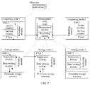
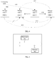
- FIG. 2 shows a logical structural diagram of a data storage system 100 according to an embodiment of the present invention.
- the data storage system 100 includes: computing nodes 1 and 2, storage nodes 1, 2, and 3, and a management node.
- each partition corresponds to one primary OSD and one secondary OSD and there is one OSD on each storage node is used as an example in the following method embodiments.
- a primary OSD is an OSD 1 on the storage node 1
- a secondary OSD is an OSD 2 on the storage node 2.
- a primary OSD is the OSD 2 on the storage node 2
- a secondary OSD is an OSD 3 on the storage node 3.
- a correspondence between the partition 1, the OSD 1, and the OSD 2 and a correspondence between the partition 2, the OSD 2, and the OSD 3 are stored on the OSD.
- a correspondence between the partition 1 and the OSD 1 and a correspondence between the partition 2 and the OSD 2 are stored in an I/O view stored on a VBS.
- a method for identifying a sub-health OSD is provided in an embodiment of the present invention covered by the scope of the appended claims and is applied to the distributed storage system shown in FIG. 2 .
- the method includes the following steps.
- a VBS in the computing node 1 receives a write data request.
- the write data request includes to-be-written data, a write location of the to-be-written data, a data length of the to-be-written data, and block device information of the to-be-written data.
- the write data request herein may be a write I/O request.
- the VBS determines, based on the write location of the to-be-written data, the data length of the to-be-written data, and the block device information of the to-be-written data included in the write data request, a primary OSD that processes the to-be-written data.
- a specific process of this step may include: dividing, by the VBS, the to-be-written data into a plurality of data blocks based on a preset length, computing, based on a consistent hashing algorithm, partition information corresponding to each data block, and then finding, based on a stored I/O view, a primary OSD corresponding to each data block.
- the to-be-written data may alternatively be less than a preset length, and the VBS classifies the to-be-written data into one data block based on the preset length.
- the to-be-written data may be divided into one or more data blocks. Therefore, there may be one or more primary OSDs corresponding to the to-be-written data.
- the to-be-written data is divided into two data blocks: a data block 1 and a data block 2. It is obtained, through calculation based on the consistent hashing algorithm, that a partition corresponding to the data block 1 is the partition 1 and a partition corresponding to the data block 2 is the partition 2. It can be learned based on the I/O view that a primary OSD corresponding to the partition 1 is the OSD 1 and a primary OSD corresponding to the partition 2 is the OSD 2.
- the VBS separately sends a write data request to a primary OSD corresponding to each data block, where the write data request includes a to-be-written data block that is to be written into the primary OSD and a partition into which the to-be-written data block is to be written; and records a time at which the write data request is sent.
- the VBS separately sends, to the OSD 1 on the storage node 1, a write data request that includes identifiers of the data block 1 and the partition 1, and sends, to the OSD on the storage node 2, a write data request that includes identifiers of the data block 2 and the partition 2.
- the following uses a processing process of the data block 1 as an example to describe a specific processing process in this embodiment of the present invention.
- the OSD 1 After receiving the write data request that includes the data block 1 and the partition 1, the OSD 1 invokes a system invoking interface of an operating system (OS) running on the storage node 1, to write the data block 1 into a persistent storage resource corresponding to the partition 1 managed by the OSD 1, and records a time at which the data block 1 is written.
- the OSD writes the data block 1 into the persistent storage resource managed by the OSD and returns a write response to the OSD 1.
- the OSD 1 obtains, by comparing the time at which the data block 1 is written and a time at which a corresponding write response is received, duration consumed for writing the data block 1 into the persistent storage resource managed by the OSD 1.
- S312 After receiving the write data request that includes the data block 1, the OSD 1 replicates the write data request to the secondary OSD of the partition 1 based on a partition allocation view, and records a time at which the write data request is sent.
- the OSD 1 on the storage node 1 replicates the write data request to the OSD 2, and records the time at which the write data request is sent.
- the OSD 2 After receiving the write data request, the OSD 2 writes the data block 1 in the write data request into a persistent storage resource managed by the OSD 2, and after persistence is completed, returns a replication response to the OSD 1.
- the OSD 2 may also record duration in which the OSD 2 writes the data block 1 into the persistent storage resource managed by the OSD 2.
- the OSD 1 After receiving the replication response returned by the OSD 2, the OSD 1 compares the recorded time at which the write data request is sent to the OSD 2 with a time at which the replication response is received, so as to obtain duration consumed for replicating the data to the secondary OSD.
- the OSD 1 may report an ID of the OSD 2 and health status information of the OSD 2 to a management node.
- the health status information of the OSD 2 is used to reflect a health status of the OSD 2.
- the health status information of the OSD 2 is duration consumed for replicating the data to a standby storage node.
- the health status information of the OSD 2 is information indicating that the OSD 2 is sub-healthy.
- the OSD 1 determines, based on the duration consumed for replicating the data to the standby storage node, whether the OSD 2 is in a sub-health state or in a health state. For example, when duration consumed for replicating the data block 1 to the standby storage node exceeds a particular threshold, it is considered that the OSD 2 is in the sub-health state.
- the ID of the OSD 2 and the information indicating that the OSD 2 is in the sub-health state may be included in a heartbeat message reported to the management node by the storage node 1 in which the OSD 1 is located.
- the information indicating the sub-health state may be a sub-health type.
- the sub-health type may also be referred to as a fault level.
- an identifier of the reporter OSD 1 is carried in a packet header of the heartbeat message reported to the management node.
- the ID of the OSD 2 and the information indicating that the OSD 2 is in the sub-health state are carried by using the following packet field:
- the OSD 1 may report the ID of the OSD 1 and health status information of the OSD 1 to the management node.
- the health status information of the OSD 1 is used to reflect a health status of the OSD 1.
- the health status information of the OSD may be the duration consumed for replicating the data to the standby storage node, or may be information indicating that the OSD 1 is in a sub-health state.
- the OSD 1 can determine the health status of the OSD 1 based on the duration consumed for writing the data block 1 into the persistent storage resource managed by the OSD 1.
- the OSD 1 determines that the OSD 1 is in the sub-health state.
- the ID of the OSD 1 and the information indicating that the OSD 1 is in the sub-health state may be included in a heartbeat message reported to the management node by the storage node 1 in which the OSD 1 is located.
- the OSD 2 may also report the ID of the OSD 2 and the health status information of the OSD 2 to the management node.
- the OSD 1 and the OSD 2 can use an existing heartbeat message to report the health status information of the OSD 1 and the OSD 2 respectively.
- the foregoing health status information of the OSD may alternatively be reported by using another message. No limitation is imposed in the present invention.
- the VBS 1 After receiving the write data response sent by the OSD 1, the VBS 1 compares a time at which the VBS 1 sends the write data request and a time at which the VBS 1 receives the write data response, so as to obtain duration for sending the write data request to the primary OSD.
- the VBS 1 can report the ID of the OSD 1 and the health status information of the OSD 1 to the management node.
- the health status information of the OSD 1 is used to reflect the health status of the OSD 1.
- the health status information of the OSD 1 may be the duration for sending the write data request to the primary OSD, or may be the information indicating that the OSD 1 is in the sub-health state.
- the OSD 1 can determine the health status of the OSD 1 based on the duration for sending the write data request to the primary OSD. For example, when the duration for sending the write data request to the primary OSD exceeds a particular threshold, it is determined that the OSD 1 is in the sub-health state.
- the ID of the OSD 1 and the information indicating that the OSD 1 is in the sub-health state may be included in a heartbeat message reported to the management node by the computing node 1 in which the VBS 1 is located.
- an identifier of the reporter is carried in a packet header of the heartbeat message reported to the management node.
- the ID of the OSD 1 and the information indicating that the OSD 1 is in the sub-health state are carried by using the following packet field.
- the management node receives health status information, reported by the foregoing storage node and/or computing node, of the storage node, determines a health status of the OSD in the data storage system based on the received health status information, and performs corresponding processing.
- each computing node and each storage node may report, when processing a write data request or a read data request, health status information of an OSD related to the write data request or the read data request.
- one OSD may serve as a primary OSD for a plurality of partitions, or serve as a secondary OSD for a plurality of other partitions.
- the management node may receive a plurality of heartbeat messages.
- a health status record table may be set on the management node to record an OSD that is in the sub-health state in the data storage system.
- a correspondence between an identifier of the sub-health OSD and an identifier of the reporter that reports the sub-health OSD may be recorded. No limitation is imposed on a recorded format in the present invention.
- the received report information may be classified into the following three types: health status information, reported by a computing node, of an OSD, health status information, reported by a storage node, of an OSD on another storage node, and health status information, reported by a storage node, of an OSD on the storage node.
- the reported health status information may be indication information indicating that an OSD is in a sub-health state, or may be a delay in processing a read/write data request.
- the delay in processing a read/write data request may include duration consumed by an OSD for writing data into a persistent storage resource managed by the OSD, duration consumed by a primary OSD for replicating the data to a secondary OSD, and duration consumed by a VBS for sending the read/write data request to the primary OSD.
- the delay in processing a read/write data request may include duration consumed by an OSD for reading the data from the persistent storage resource managed by the OSD, and duration consumed by a VBS for sending the read/write data request to the primary OSD.
- the management node may manage the OSD based on a specified management policy.
- the health status information reported by each node is indication information indicating that the OSD is in the sub-health state.
- the management node separately manages the foregoing three types of information.
- the management node For the health status information, reported by a computing node, of an OSD, the management node performs the following steps.
- S322-11 Obtain a quantity of computing nodes in the data storage system that have processed read/write data requests in a time period, and record the quantity of the computing nodes as X.
- S322-12 In n primary OSDs related to all the foregoing read/write data requests, count a quantity of computing nodes that report that each primary OSD is in the sub-health state, and record the quantity of the computing nodes that report each primary OSD as Yi, where i is an integer from 1 to n.
- S322-13 For each primary OSD, calculate whether a proportion (Yi/X) of the computing nodes that report the sub-health state of the primary OSD is in a preset range, and if the proportion (Yi/X) is in the preset range, determine that the primary OSD is in the sub-health state, and perform permanent isolation or online temporary isolation on the primary OSD based on a fault level of the primary OSD.
- the fault level can be determined based on factors such as a value of the delay in processing the read/write data request and a proportion of computing nodes affected by the delay.
- the proportion of the computing nodes may be Y/X.
- the management node For health status information, reported by a storage node, of an OSD on another storage node, the management node performs the following steps.
- the active storage node herein is a storage node in which a primary OSD is located. It can be understood that the primary OSD corresponds to a partition, and a primary OSD of a partition may be a secondary OSD of another partition. Therefore, a same storage node can serve as an active storage node, or a standby storage node.
- S322-22 In n secondary OSDs related to the foregoing replication operations, count a quantity of other storage nodes that report that each secondary OSD is in the sub-health state, and record the quantity of the other storage nodes that report each OSD as Y'i, where i is an integer from 1 to n.
- secondary OSDs related to the foregoing replication operations obtain, through statistics collection, a secondary OSD that is reported to be sub-healthy by a largest quantity of other storage nodes, and record a quantity of the other storage nodes that report the secondary OSD as Y.
- S322-23 For each secondary OSD, calculate whether a proportion (Y'i/X') of the storage nodes that report the sub-health state of the secondary OSD is in a preset range, and if the proportion (Y'i/X') is in the preset range, determine that the storage node is sub-healthy, and perform permanent isolation or online temporary isolation on the storage node based on a fault level of the storage node.
- the fault level can be determined based on factors such as a value of the delay in processing the read/write data request and a proportion of storage nodes affected by the delay.
- the management node For health status information, reported by a storage node, of an OSD on the storage node, the management node performs the following step:
- the health status information received by the management node is the delay in processing the read/write data request.
- the management node determines, based on a particular policy, which OSD in the data storage system is in the sub-health state and needs to be temporarily isolated or permanently isolated.
- a delay that may be encountered in a path for processing the read/write data request is detected, so that a health status of each node in the data storage system is detected more comprehensively and accurately, and the sub-health OSD is correspondingly processed based on a detection result.
- each OSD may be a primary OSD of a plurality of partitions, or a secondary OSD of some other partitions.
- OSD 2 it is assumed that in actual deployment, the OSD 2 is a secondary OSD of X partitions, and is also a primary OSD of Y partitions. Then, X+Y partitions are partitions managed by the OSD 2.
- another OSD needs to take over the partitions managed by the OSD 2.
- a write data request that carries the data may be allocated to an OSD that takes over the OSD 2.
- an OSD in a sub-health state is referred to as a sub-health OSD; and an OSD used to take over a partition managed by the sub-health OSD is referred to as a takeover OSD.
- the partition managed by the OSD 2 may be allocated to a plurality of takeover OSDs, or allocated to one takeover OSD. Specific allocation may be determined based on factors such as load of OSDs in the storage system, or determined based on some preset policies.
- a management node allocates a takeover OSD to the OSD 2, and the takeover OSD takes over the partition managed by the sub-health OSD to take the place of the sub-health OSD to process a subsequent write data request.
- the management node may use the following algorithm to select a takeover node for the sub-health storage node.
- a collision domain is usually preset in a data storage system.
- an OSD in a storage node in which capacity is lower and a persistent storage resource has no fault is preferentially selected as a takeover OSD, to ensure that storage of a cluster is balanced and dispersed.
- a cabinet that occupies lowest capacity is selected from cabinets that have no collisions.
- a server that occupies lowest capacity is selected, and in the server, a storage node that occupies lowest capacity and has no fault in a persistent storage resource is selected.
- the collision domain is set as the cabinet.
- an OSD 4 is determined as the takeover OSD of the OSD 2. It can be understood that there may be a plurality of takeover OSDs to take over the partition managed by the OSD 2. No limitation is imposed in the present invention.
- the management node selects the takeover node OSD 4 to take over the partition managed by the sub-health node OSD 2, the OSD 4 becomes a secondary OSD of the X partitions originally managed by the OSD 2.
- the OSD 2 is also a primary OSD of the Y partitions. Therefore, before the OSD 4 takes over the Y partitions, the original OSD 2 is degraded to a secondary OSD of the Y partitions, and an original secondary OSD of the Y partitions is upgraded to a primary OSD. Then, the OSD 4 takes the place of the OSD 2 to serve as the secondary OSD of the Y partitions.
- an MDC updates a partition allocation view of the data storage system based on these changes, and sends an updated partition allocation view to an OSD in a storage node. Because of addition of the takeover node, the updated partition allocation view may further include a correspondence between the sub-health node and the takeover node.
- a switching process includes the following steps (some steps are not shown in the figure).
- S404 The management node sends an updated partition allocation view to all computing nodes in a storage system, the takeover node, and an OSD related to the partition taken over by the takeover OSD.
- the OSD 4 becomes a secondary OSD of the X+Y partitions, and a current primary OSD of the X+Y partitions may be referred to as the OSD related to the partition taken over by the takeover OSD.
- the partition allocation view is updated. Therefore, the management node sends the updated partition allocation view to a related node in the storage system.
- a VBS in a computing node 1 determines, based on a write location of to-be-written data, a data length of the to-be-written data, and block device information of the to-be-written data that are included in the write data request, a primary OSD that processes the to-be-written data.
- the VBS divides, based on a preset length, the to-be-written data carried in the write data request into a plurality of data blocks, computes, based on a consistent hashing algorithm, partition information corresponding to each data block, and finds a corresponding primary OSD based on a stored I/O view.
- the to-be-written data is divided into two data blocks: a data block 1 and a data block 2. It is obtained, through calculation based on the consistent hashing algorithm, that a partition corresponding to the data block 1 is the partition 1 and a partition corresponding to the data block 2 is a partition 2.
- a primary OSD corresponding to the partition 1 is an OSD 1 and a primary OSD corresponding to the partition 2 is the OSD 2. If before the takeover, a secondary OSD corresponding to the partition 1 is the OSD 2 and a secondary OSD of the partition 2 is an OSD 3, after the takeover, the primary OSD corresponding to the partition 1 is still the OSD 1, the secondary OSD corresponding to the partition 1 is the OSD 4, the primary OSD of the partition 2 is the OSD 3, and the secondary OSD of the partition 2 is the OSD 4.
- the VBS sends a write data request to the OSD 1 based on an updated I/O view, where the write data request sent to the OSD 1 includes identifiers of the data block 1 and the partition 1.
- the VBS also sends a write data request to the OSD 3 based on the updated I/O view, where the write data request sent to the OSD 3 includes identifiers of the data block 2 and the partition 2.
- S412 After receiving the write data request that includes the identifiers of the data block 1 and the partition 1, the OSD 4 learns, based on the stored partition allocation view, that the OSD 4 is the secondary OSD of the partition 1 and is a takeover OSD of the OSD 2. The OSD 4 writes the data block 1 into a persistent storage resource managed by the OSD 4, and obtains duration consumed for writing the data block 1 into the persistent storage resource.
- the OSD 4 further sends the write data request that includes the data block 1 to a background handoff thread, where the handoff thread asynchronously sends the write data request to the OSD 2; and records a time at which the write data request is sent.
- S416 After receiving a write response returned by the OSD 2, the OSD 4 determines, based on the time, recorded in S414, at which the write data request is sent and a time at which the write response is received, duration required for synchronizing the data to the sub-health OSD (OSD 2).
- the OSD 4 determines, based on a specified policy, whether to report health status information of the OSD 2 to the management node. For example, when the duration required for synchronizating the data to the OSD 2 exceeds a threshold, the health status information of the OSD 2 is sent to the management node.
- a method for reporting the health status information of the OSD 2 refer to description in the foregoing embodiment. Details are not described herein again.
- S416 The management node determines a health status of the sub-health OSD based on received health status information.
- a method for determining a health status of an OSD by the management node refer to the foregoing embodiment. Details are not described herein again.
- the VBS sends, to the OSD 3, the write data request that includes the identifiers of the data block 2 and the partition 2.
- the following describes a processing process after the OSD 3 receives the write data request that includes the identifiers of the data block 2 and the partition 2.
- the OSD 3 learns, based on the updated partition allocation view, that the OSD 3 is a primary OSD of the partition 2.
- the OSD 3 writes the data block 2 into a persistent storage resource managed by the OSD 3, and obtains duration consumed for writing the data block 2 into the persistent storage resource.
- the OSD 3 learns, based on the updated partition allocation view, that the secondary OSD of the partition 2 is a sub-health node and a takeover node of the sub-health node is the OSD 4, and replicates the write data request to the takeover node OSD 4.
- the OSD 4 learns, based on a locally stored updated partition allocation view, that the OSD 4 is the takeover node of the sub-health OSD (OSD 2) and the OSD 2 is the secondary OSD of the partition 2.
- the OSD 4 sends the write data request that includes the data block 2 to a background handoff thread, where the handoff thread asynchronously sends the write data request to the OSD 2; and records a time at which the write data request is sent.
- S424 After receiving a write response returned by the OSD 2, the OSD 4 determines, based on the time, recorded in S422, at which the write data request is sent and a time at which the write response is received, duration required for synchronizing the data to the OSD (OSD 2) before the takeover.
- the OSD 4 determines, based on a specified policy, whether to report the health status information of the OSD 2 to the management node. For example, when the duration required for synchronizating the data to the OSD 2 exceeds a threshold, the health status information of the OSD 2 is sent to the management node.
- a method for reporting the health status information of the OSD 2 refer to description in the foregoing embodiment. Details are not described herein again.
- the partition allocation view is updated accordingly.
- the partition allocation view a correspondence between the OSD 2 and the takeover node is deleted.
- the I/O view stored on the computing node or the partition allocation view stored on the OSD are updated. In this case, it can be determined, based on stored optimal partition allocation, whether identities of active and secondary OSDs need to be refreshed.
- the OSD 2 is a primary OSD of some partitions.
- the OSD 2 is degraded to a secondary OSD of these partitions, and the original secondary OSD is upgraded to the primary OSD of these partitions.
- the active and secondary OSDs of these partitions can also be switched back.
- a manner of switching back the active and secondary OSDs may be: after the management node determines that the OSD 2 is restored to healthy, updating the partition allocation view, and in the updated partition allocation view, for these partitions, switching back the identities of the active and secondary OSDs.
- the takeover node After the OSD 2 in the sub-health state is isolated online, the takeover node asynchronously pushes the received write data request to the OSD 2 by using the handoff thread. Therefore, for the partition 1, the OSD 2 and the OSD 1 maintain data consistency. For the partition 2, the OSD 2 and the OSD 3 maintain data consistency. Once a fault of the OSD 2 is rectified, the OSD 2 can be directly put into use.
- the management node can remove the OSD 2 from the data storage system.
- the VBS, the OSD, and the management node (MDC) that are mentioned in the foregoing embodiments may be implemented by using a software module that is installed on a hardware device of a server.
- the VBS, the OSD, and the management node each may include a processor 501 and a memory 502, where the processor 501 and the memory 502 implement mutual communication through a bus.
- the memory 502 is configured to store a computer operation instruction, and may be specifically a high-speed RAM memory or a nonvolatile memory.
- the processor 501 is configured to execute the computer operation instruction stored in the memory.
- the processor 501 may be specifically a central processing unit (CPU), an application-specific integrated circuit (ASIC), or one or more integrated circuits configured to implement this embodiment of the present invention.
- the processor 501 executes different computer operation instructions stored in the memory 502 to perform actions of the VBS, the OSD, and the MDC in the foregoing embodiments, so as to implement functions of the VBS, the OSD, and the MDC.
- FIG. 1 Another example of the present not covered by the scope of the appended claims provides a storage medium, configured to store the computer operation instruction mentioned in the foregoing example.
- the operations instruction stored in the storage medium is executed by a computer, the methods in the foregoing embodiments can be performed, so as to implement a function of the foregoing MDC, VBS, or OSD in a data storage system.
Landscapes
- Engineering & Computer Science (AREA)
- Theoretical Computer Science (AREA)
- Human Computer Interaction (AREA)
- Physics & Mathematics (AREA)
- General Engineering & Computer Science (AREA)
- General Physics & Mathematics (AREA)
- Computer Security & Cryptography (AREA)
- Computer Networks & Wireless Communication (AREA)
- Stored Programmes (AREA)
- Information Retrieval, Db Structures And Fs Structures Therefor (AREA)
Claims (18)
- Datenspeichersystem, wobei das System einen Verwaltungsknoten und eine Vielzahl von Speicherknoten umfasst, wobei eine Vielzahl von Objektspeichervorrichtungen, OSDs, im System bereitgestellt sind, sich die Vielzahl von OSDs auf der Vielzahl von Speicherknoten befinden und die Vielzahl von OSDs eine erste OSD und eine zweite OSD umfassen, wobeidie erste OSD ausgelegt ist zum: Empfangen einer ersten Datenschreibanforderung, wobei die erste Datenschreibanforderung einen zu schreibenden ersten Datenblock und eine entsprechende mit Daten zu beschreibende Partition umfasst; Bestimmen, basierend auf einer Partitionszuordnungsansicht, dass eine sekundäre OSD der mit Daten zu beschreibenden Partition die zweite OSD ist; Replizieren der ersten Datenschreibanforderung auf die zweite OSD und Senden einer ersten Berichtsnachricht an den Verwaltungsknoten, nachdem eine Dauer, die für das Replizieren des ersten Datenblocks auf die zweite OSD aufgewendet wurde, erhalten wird, wobei die erste Berichtsnachricht einen Identifikator der ersten OSD, einen Identifikator der zweiten OSD und Integritätsstatusinformationen der zweiten OSD umfasst, wobei die Integritätsstatusinformationen der zweiten OSD Informationen sind, die angeben, dass die zweite OSD in einem Subintegritätszustand ist, der basierend auf der Dauer, die für das Replizieren des ersten Datenblocks auf die zweite OSD aufgewendet wurde, bestimmt wird; undder Verwaltungsknoten ausgelegt ist zum: Empfangen der ersten Berichtsnachricht; Aktualisieren, basierend auf der ersten Berichtsnachricht, eines OSD-Integritätsstatus-Datensatzes, der auf dem Verwaltungsknoten gespeichert ist; und Bestimmen, basierend auf dem OSD-Integritätsstatus-Datensatz, dass die zweite OSD eine Subintegritäts-OSD ist, wobei der OSD-Integritätsstatus-Datensatz Integritätsstatusinformationen, die durch mehrere andere OSDs in der Vielzahl von OSDs berichtet werden, der zweiten OSD umfasst, wobei der Verwaltungsknoten zum Bestimmen, dass die zweite OSD eine Subintegritäts-OSD ist, durch Berechnen, ob ein Anteil der Speicherknoten, die den Subintegritätszustand der zweiten OSD in einem ersten Zeitraum berichten, in einem ersten vorgegebenen Bereich ist, ausgelegt ist, wobei der Verwaltungsknoten eine Metadatensteuerung, MDC, umfasst und wobei, wenn der Anteil der Speicherknoten, die den Subintegritätszustand der zweiten OSD im ersten Zeitraum berichten, im ersten vorgegebenen Bereich ist, der Verwaltungsknoten ferner zum Durchführen einer permanenten Isolierung oder vorübergehenden Online-Isolierung auf der zweiten OSD basierend auf einer Fehlerebene der zweiten OSD, die basierend auf dem Anteil der berichtenden Speicherknoten bestimmt wird, ausgelegt ist; undwobei das System ferner eine Vielzahl von Rechenknoten umfasst, wobei der Rechenknoten ausgelegt ist zum: Empfangen einer zweiten Datenschreibanforderung; Teilen von zu schreibenden Daten, die in der zweiten Datenschreibanforderung enthalten sind, in zumindest einen zu schreibenden Datenblock, wobei der zumindest eine zu schreibende Datenblock der zweiten Datenschreibanforderung den ersten Datenblock umfasst; Bestimmen einer Partition, in die jeder Datenblock in dem zumindest einen Datenblock geschrieben werden soll; Bestimmen, basierend auf einer E/A-Ansicht, dass eine primäre OSD, die den zu schreibenden ersten Datenblock verarbeitet, die erste OSD umfasst; und Senden der ersten Datenschreibanforderung an die erste OSD.
- System nach Anspruch 1,wobei der Rechenknoten ferner ausgelegt ist zum: Senden einer zweiten Berichtsnachricht an den Verwaltungsknoten, nachdem die Dauer, die für das Senden der ersten Datenschreibanforderung an die erste OSD aufgewendet wurde, erhalten wird, wobei die zweite Berichtsnachricht einen Identifikator des Rechenknotens, den Identifikator der ersten OSD und Integritätsstatusinformationen der ersten OSD umfasst, wobei die Integritätsstatusinformationen der ersten OSD Informationen sind, die angeben, dass die erste OSD im Subintegritätszustand ist, der basierend auf der Dauer, die für das Senden der ersten Datenschreibanforderung an die erste OSD aufgewendet wurde, bestimmt wird; undder Verwaltungsknoten ferner ausgelegt ist zum: Aktualisieren, basierend auf der zweiten Berichtsnachricht, des OSD-Integritätsstatus-Datensatzes, der auf dem Verwaltungsknoten erfasst ist; und Bestimmen, basierend auf dem OSD-Integritätsstatus-Datensatz, dass die erste OSD eine Subintegritäts-OSD ist, wobei der OSD-Integritätsstatus-Datensatz Integritätsstatusinformationen, die durch eine andere OSD und mehrere andere Rechenknoten in der Vielzahl von Rechenknoten berichtet werden, der ersten OSD umfasst, wobei der Verwaltungsknoten zum Bestimmen, dass die erste OSD eine Subintegritäts-OSD ist, durch Berechnen, ob ein Anteil der Rechenknoten, die den Subintegritätszustand der ersten OSD in einem zweiten Zeitraum berichten, in einem zweiten vorgegebenen Bereich ist, ausgelegt ist und wobei, wenn der Anteil der Rechenknoten, die den Subintegritätszustand der ersten OSD im zweiten Zeitraum berichten, im zweiten vorgegebenen Bereich ist, der Verwaltungsknoten ferner zum Durchführen einer permanenten Isolierung oder vorübergehenden Online-Isolierung auf der ersten OSD basierend auf einer Fehlerebene der ersten OSD, die basierend auf dem Anteil der berichtenden Rechenknoten bestimmt wird, ausgelegt ist.
- System nach Anspruch 1,wobei der Rechenknoten ferner ausgelegt ist zum: Empfangen einer ersten Datenleseanforderung; Bestimmen einer Partition, in der sich jeder zu lesende Datenblock, der durch die erste Datenleseanforderung zu lesen ist, befindet; Bestimmen, basierend auf einer E/A-Ansicht, dass eine primäre OSD, die den zu lesenden Datenblock verarbeitet, die erste OSD umfasst; Senden einer zweiten Datenleseanforderung an die erste OSD und Senden einer zweiten Berichtsnachricht an den Verwaltungsknoten, nachdem die Dauer, die für das Senden der zweiten Datenleseanforderung an die erste OSD aufgewendet wurde, erhalten wird, wobei die zweite Berichtsnachricht einen Identifikator des Rechenknotens, den Identifikator der ersten OSD und Integritätsstatusinformationen der ersten OSD umfasst und die zweite Datenleseanforderung die Partition umfasst, in der sich der zu lesende Datenblock befindet, wobei die Integritätsstatusinformationen der ersten OSD Informationen sind, die angeben, dass die erste OSD im Subintegritätszustand ist, der basierend auf der Dauer, die für das Senden der zweiten Datenleseanforderung an die erste OSD aufgewendet wurde, bestimmt wird; undder Verwaltungsknoten ferner ausgelegt ist zum: Empfangen der zweiten Berichtsnachricht; Aktualisieren, basierend auf der zweiten Berichtsnachricht, des OSD-Integritätsstatus-Datensatzes, der auf dem Verwaltungsknoten gespeichert ist; und Bestimmen, basierend auf dem OSD-Integritätsstatus-Datensatz, dass die erste OSD eine Subintegritäts-OSD ist, wobei der OSD-Integritätsstatus-Datensatz Integritätsstatusinformationen, die durch eine andere OSD und mehrere andere Rechenknoten in der Vielzahl von Rechenknoten berichtet werden, der ersten OSD umfasst, wobei der Verwaltungsknoten zum Bestimmen, dass die erste OSD eine Subintegritäts-OSD ist, durch Berechnen, ob ein Anteil der Rechenknoten, die den Subintegritätszustand der ersten OSD in einem zweiten Zeitraum berichten, in einem zweiten vorgegebenen Bereich ist, ausgelegt ist und wobei, wenn der Anteil der Rechenknoten, die den Subintegritätszustand der ersten OSD im zweiten Zeitraum berichten, im zweiten vorgegebenen Bereich ist, der Verwaltungsknoten ferner zum Durchführen einer permanenten Isolierung oder vorübergehenden Online-Isolierung auf der ersten OSD basierend auf einer Fehlerebene der ersten OSD, die basierend auf dem Anteil der berichtenden Rechenknoten bestimmt wird, ausgelegt ist.
- System nach Anspruch 1, wobeidie erste OSD ferner ausgelegt ist zum: Schreiben, in eine Dauerspeicherressource entsprechend der entsprechenden mit Daten zu beschreibenden Partition, des ersten Datenblocks, der in eine Partition geschrieben werden soll, die durch die erste OSD verwaltet wird; und Senden einer dritten Berichtsnachricht an den Verwaltungsknoten, nachdem die Dauer, die für das Schreiben des ersten Datenblocks in die Dauerspeicherressource aufgewendet wurde, erhalten wird, wobei die dritte Berichtsnachricht den Identifikator der ersten OSD und Integritätsstatusinformationen der ersten OSD umfasst, wobei die Integritätsstatusinformationen der ersten OSD Informationen sind, die angeben, dass die erste OSD im Subintegritätszustand ist, der basierend auf der Dauer, die für das Schreiben des ersten Datenblocks in die Dauerspeicherressource aufgewendet wurde, bestimmt wird; undder Verwaltungsknoten zum Bestimmen, basierend auf der dritten Berichtsnachricht, dass die erste OSD eine Subintegritäts-OSD ist, ausgelegt ist.
- System nach einem der Ansprüche 2 bis 3, wobeider Verwaltungsknoten ausgelegt ist zum: Bestimmen, in der Vielzahl von OSDs, einer Übernahme-OSD der Subintegritäts-OSD, wobei die Übernahme-OSD zum Übernehmen der durch die Subintegritäts-OSD verwalteten Partition verwendet wird; Feststellen einer Übereinstimmung zwischen der Subintegritäts-OSD und der Übernahme-OSD; Aktualisieren der Partitionszuordnungsansicht basierend auf der Übereinstimmung zwischen der Subintegritäts-OSD und der Übernahme-OSD, wobei eine aktualisierte Partitionszuordnungsansicht eine aktualisierte E/A-Ansicht umfasst; und Senden der aktualisierten E/A-Ansicht an die Vielzahl von Rechenknoten und Senden der aktualisierten Partitionszuordnungsansicht an die Übernahme-OSD und eine OSD, die eine Aktiv-Standby-Beziehung zur Subintegritäts-OSD aufweist, wobei die Übernahme-OSD von der ersten OSD und der zweiten OSD verschieden ist;der Rechenknoten ausgelegt ist zum: Empfangen einer dritten Datenschreibanforderung; Teilen von zu schreibenden Daten, die in der dritten Datenschreibanforderung enthalten sind, in zumindest einen zu schreibenden Datenblock; Bestimmen einer Partition, in die jeder zu schreibende Datenblock im zumindest einen Datenblock geschrieben werden soll; Bestimmen, basierend auf der E/A-Ansicht, dass eine primäre OSD, die den zumindest einen zu schreibenden Datenblock verarbeitet, eine dritte OSD umfasst; und Senden einer vierten Datenschreibanforderung an die dritte OSD, wobei die vierte Datenschreibanforderung einen Datenblock, der in eine Partition geschrieben werden soll, die durch die dritte OSD verwaltet wird, und die entsprechende mit Daten zu beschreibende Partition umfasst und die dritte OSD eine der Vielzahl von OSDs ist und von der Übernahme-OSD verschieden ist;nach dem Empfangen der vierten Datenschreibanforderung, die dritte OSD die vierte Datenschreibanforderung basierend auf der aktualisierten Partitionszuordnungsansicht auf die Übernahme-OSD repliziert, wobei, in der aktualisierten Partitionszuordnungsansicht, eine sekundäre OSD entsprechend der mit Daten zu beschreibenden Partition, die in der vierten Datenschreibanforderung enthalten ist, die Subintegritäts-OSD ist; unddie Übernahme-OSD ferner zum Synchronisieren der empfangenen vierten Datenschreibanforderung basierend auf der aktualisierten Partitionszuordnungsansicht auf die Subintegritäts-OSD ausgelegt ist.
- System nach Anspruch 5, wobeidie Übernahme-OSD ferner zum Senden einer vierten Berichtsnachricht an den Verwaltungsknoten ausgelegt ist, nachdem die Dauer, die für das Synchronisieren der dritten Datenschreibanforderung auf die Subintegritäts-OSD aufgewendet wurde, erhalten wird, wobei die vierte Berichtsnachricht einen Identifikator der Übernahme-OSD, einen Identifikator der Subintegritäts-OSD und dritte Integritätsstatusinformationen der Subintegritäts-OSD umfasst, wobei die Integritätsstatusinformationen der Subintegritäts-OSD Informationen sind, die angeben, dass die Subintegritäts-OSD in einem Integritätszustand ist, der basierend auf der Dauer, die für das Synchronisieren der dritten Datenschreibanforderung auf die Subintegritäts-OSD aufgewendet wurde, bestimmt wird; undder Verwaltungsknoten ferner ausgelegt ist zum: Aktualisieren, basierend auf der vierten Berichtsnachricht, des OSD-Integritätsstatus-Datensatzes, der auf dem Verwaltungsknoten erfasst ist; und Bestimmen, basierend auf einem aktualisierten OSD-Integritätsstatus-Datensatz, dass die Subintegritäts-OSD auf normal wiederhergestellt ist, wobei der OSD-Integritätsstatus-Datensatz Integritätsstatusinformationen, die durch eine andere OSD berichtet werden, der Subintegritäts-OSD umfasst.
- System nach einem der Ansprüche 1 bis 4, wobei
die erste OSD ausgelegt ist zum: Empfangen einer Replikationsantwort, die durch die zweite OSD zurückgegeben wird; und Erhalten, durch Vergleichen einer Zeit, zu der die erste Datenschreibanforderung gesendet wird, und einer Zeit, zu der die Replikationsantwort empfangen wird, der Dauer, die für das Replizieren des ersten Datenblocks auf die zweite OSD aufgewendet wurde. - System nach Anspruch 2, wobei
der Rechenknoten ferner ausgelegt ist zum: Empfangen einer ersten Datenschreibantwort, die durch die erste OSD zurückgegeben wird; und Erhalten, durch Vergleichen einer Zeit, zu der die erste Datenschreibanforderung gesendet wird, und einer Zeit, zu der die erste Datenschreibantwort empfangen wird, der Dauer, die für das Senden der ersten Datenschreibanforderung an die erste OSD aufgewendet wurde. - System nach Anspruch 3, wobei
der Rechenknoten ferner ausgelegt ist zum: Empfangen einer Datenleseantwort, die durch die erste OSD zurückgegeben wird, für die zweite Datenleseanforderung und Erhalten, durch Vergleichen einer Zeit, zu der die zweite Datenleseanforderung gesendet wird, und einer Zeit, zu der die Datenleseantwort empfangen wird, der Dauer, die für das Senden der zweiten Datenleseanforderung an die erste OSD aufgewendet wurde. - Verfahren zum Identifizieren einer Subintegritätsobjektspeichervorrichtung, Subintegritäts-OSD, die zur Replikation einer ersten Datenschreibanforderung verwendet wird, wobei das Verfahren auf ein Datenspeichersystem angewendet wird, das Datenspeichersystem einen Verwaltungsknoten und eine Vielzahl von Speicherknoten umfasst, eine Vielzahl von OSDs im System bereitgestellt sind, sich die Vielzahl von OSDs auf der Vielzahl von Speicherknoten befinden, die Vielzahl von OSDs eine erste OSD und eine zweite OSD umfassen und das Verfahren umfasst:Empfangen, durch die erste OSD, der ersten Datenschreibanforderung, wobei die erste Datenschreibanforderung einen ersten Datenblock, der in eine Partition geschrieben werden soll, die durch die erste OSD verwaltet wird, und die entsprechende mit Daten zu beschreibende Partition umfasst; Bestimmen, basierend auf einer Partitionszuordnungsansicht, dass eine sekundäre OSD der mit Daten zu beschreibenden Partition die zweite OSD ist; Replizieren der ersten Datenschreibanforderung auf die zweite OSD und Senden einer ersten Berichtsnachricht an den Verwaltungsknoten, nachdem eine Dauer, die für das Replizieren des ersten Datenblocks auf die zweite OSD aufgewendet wurde, erhalten wird, wobei die erste Berichtsnachricht einen Identifikator der ersten OSD, einen Identifikator der zweiten OSD und Integritätsstatusinformationen der zweiten OSD umfasst, wobei die Integritätsstatusinformationen der zweiten OSD Informationen sind, die angeben, dass die zweite OSD in einem Subintegritätszustand ist, der basierend auf der Dauer, die für das Replizieren des ersten Datenblocks auf die zweite OSD aufgewendet wurde, bestimmt wird; undEmpfangen, durch den Verwaltungsknoten, der ersten Berichtsnachricht; Aktualisieren, basierend auf der ersten Berichtsnachricht, eines OSD-Integritätsstatus-Datensatzes, der auf dem Verwaltungsknoten gespeichert ist; und Bestimmen, basierend auf dem OSD-Integritätsstatus-Datensatz, dass die zweite OSD eine Subintegritäts-OSD ist, wobei der OSD-Integritätsstatus-Datensatz Integritätsstatusinformationen, die durch mehrere andere OSDs berichtet werden, der zweiten OSD umfasst, wobei der Verwaltungsknoten bestimmt, dass die zweite OSD eine Subintegritäts-OSD ist, durch Berechnen, ob ein Anteil der Speicherknoten, die den Subintegritätszustand der zweiten OSD in einem ersten Zeitraum berichten, in einem ersten vorgegebenen Bereich ist, wobei der Verwaltungsknoten eine Metadatensteuerung, MDC, umfasst und wobei, wenn der Anteil der Speicherknoten, die den Subintegritätszustand der zweiten OSD im ersten Zeitraum berichten, im ersten vorgegebenen Bereich ist, der Verwaltungsknoten ferner eine permanente Isolierung oder vorübergehende Online-Isolierung auf der zweiten OSD basierend auf einer Fehlerebene der zweiten OSD, die basierend auf dem Anteil der berichtenden Speicherknoten bestimmt wird, durchführt;wobei das System ferner eine Vielzahl von Rechenknoten umfasst und, vor dem Empfangen, durch die erste OSD, einer ersten Datenschreibanforderung, das Verfahren umfasst:
Empfangen, durch den Rechenknoten, einer zweiten Datenschreibanforderung; Teilen von zu schreibenden Daten, die in der zweiten Datenschreibanforderung enthalten sind, in zumindest einen zu schreibenden Datenblock, wobei der zumindest eine zu schreibende Datenblock den ersten Datenblock umfasst; Bestimmen einer Partition, in die jeder Datenblock in dem zumindest einen Datenblock geschrieben werden soll; Bestimmen, basierend auf einer E/A-Ansicht, dass eine primäre OSD, die den zu schreibenden ersten Datenblock verarbeitet, die erste OSD umfasst; und Senden der ersten Datenschreibanforderung an die erste OSD. - Verfahren nach Anspruch 10, ferner umfassend:Senden, durch den Rechenknoten, einer zweiten Berichtsnachricht an den Verwaltungsknoten, nachdem die Dauer, die für das Senden der ersten Datenschreibanforderung an die erste OSD aufgewendet wurde, erhalten wird, wobei die zweite Berichtsnachricht einen Identifikator des Rechenknotens, den Identifikator der ersten OSD und Integritätsstatusinformationen der ersten OSD umfasst, wobei die Integritätsstatusinformationen der ersten OSD Informationen sind, die angeben, dass die erste OSD im Subintegritätszustand ist, der basierend auf der Dauer, die für das Senden der ersten Datenschreibanforderung an die erste OSD aufgewendet wurde, bestimmt wird; undAktualisieren, durch den Verwaltungsknoten, basierend auf der zweiten Berichtsnachricht, des OSD-Integritätsstatus-Datensatzes, der auf dem Verwaltungsknoten erfasst ist; und Bestimmen, basierend auf dem OSD-Integritätsstatus-Datensatz, dass die erste OSD eine Subintegritäts-OSD ist, wobei der OSD-Integritätsstatus-Datensatz Integritätsstatusinformationen, die durch eine andere OSD und mehrere andere Rechenknoten in der Vielzahl von Rechenknoten berichtet werden, der ersten OSD umfasst, wobei der Verwaltungsknoten bestimmt, dass die erste OSD eine Subintegritäts-OSD ist, durch Berechnen, ob ein Anteil der Rechenknoten, die den Subintegritätszustand der ersten OSD in einem zweiten Zeitraum berichten, in einem zweiten vorgegebenen Bereich ist, und wobei, wenn der Anteil der Rechenknoten, die den Subintegritätszustand der ersten OSD im zweiten Zeitraum berichten, im zweiten vorgegebenen Bereich ist, der Verwaltungsknoten eine permanente Isolierung oder vorübergehende Online-Isolierung auf der ersten OSD basierend auf einer Fehlerebene der ersten OSD, die basierend auf dem Anteil der berichtenden Rechenknoten bestimmt wird, durchführt.
- Verfahren nach Anspruch 10, ferner umfassend:Empfangen, durch die Rechenknoten, einer ersten Datenleseanforderung; Bestimmen einer Partition, in der sich jeder zu lesende Datenblock, der durch die erste Datenleseanforderung zu lesen ist, befindet; Bestimmen, basierend auf einer E/A-Ansicht, dass eine primäre OSD, die den zu lesenden Datenblock verarbeitet, die erste OSD umfasst; Senden einer zweiten Datenleseanforderung an die erste OSD und Senden einer zweiten Berichtsnachricht an den Verwaltungsknoten, nachdem die Dauer, die für das Senden der zweiten Datenleseanforderung an die erste OSD aufgewendet wurde, erhalten wird, wobei die zweite Berichtsnachricht einen Identifikator des Rechenknotens, den Identifikator der ersten OSD und Integritätsstatusinformationen der ersten OSD umfasst und die zweite Datenleseanforderung die Partition umfasst, in der sich der zu lesende Datenblock befindet, wobei die Integritätsstatusinformationen der ersten OSD Informationen sind, die angeben, dass die erste OSD im Subintegritätszustand ist, der basierend auf der Dauer, die für das Senden der zweiten Datenleseanforderung an die erste OSD aufgewendet wurde, bestimmt wird; undEmpfangen, durch den Verwaltungsknoten, der zweiten Berichtsnachricht; Aktualisieren, basierend auf der zweiten Berichtsnachricht, des OSD-Integritätsstatus-Datensatzes, der auf dem Verwaltungsknoten gespeichert ist; und Bestimmen, basierend auf dem OSD-Integritätsstatus-Datensatz, dass die erste OSD eine Subintegritäts-OSD ist, wobei der OSD-Integritätsstatus-Datensatz Integritätsstatusinformationen, die durch eine andere OSD und mehrere andere Rechenknoten in der Vielzahl von Rechenknoten berichtet werden, der ersten OSD umfasst, wobei der Verwaltungsknoten bestimmt, dass die erste OSD eine Subintegritäts-OSD ist, durch Berechnen, ob ein Anteil der Rechenknoten, die den Subintegritätszustand der ersten OSD in einem zweiten Zeitraum berichten, in einem zweiten vorgegebenen Bereich ist, und wobei, wenn der Anteil der Rechenknoten, die den Subintegritätszustand der ersten OSD im zweiten Zeitraum berichten, im zweiten vorgegebenen Bereich ist, der Verwaltungsknoten eine permanente Isolierung oder vorübergehende Online-Isolierung auf der ersten OSD basierend auf einer Fehlerebene der ersten OSD, die basierend auf dem Anteil der berichtenden Rechenknoten bestimmt wird, durchführt.
- Verfahren nach Anspruch 10, wobei, nach dem Empfangen, durch die erste OSD, der ersten Datenschreibanforderung, das Verfahren ferner umfasst:Schreiben, durch die erste OSD in eine Dauerspeicherressource entsprechend der Partition, die durch die erste OSD verwaltet wird, des ersten Datenblocks, der in die Partition geschrieben werden soll, die durch die erste OSD verwaltet wird; und Senden einer dritten Berichtsnachricht an den Verwaltungsknoten, nachdem die Dauer, die für das Schreiben des ersten Datenblocks in die Dauerspeicherressource aufgewendet wurde, erhalten wird, wobei die dritte Berichtsnachricht den Identifikator der ersten OSD und Integritätsstatusinformationen der ersten OSD umfasst, wobei die Integritätsstatusinformationen der ersten OSD Informationen sind, die angeben, dass die erste OSD im Subintegritätszustand ist, der basierend auf der Dauer, die für das Schreiben des ersten Datenblocks in die Dauerspeicherressource aufgewendet wurde, bestimmt wird; undBestimmen, durch den Verwaltungsknoten basierend auf der dritten Berichtsnachricht, dass die erste OSD eine Subintegritäts-OSD ist.
- Verfahren nach einem der Ansprüche 10 bis 12, wobei, nach dem Bestimmen, durch den Verwaltungsknoten, einer Subintegritäts-OSD, das Verfahren ferner umfasst:Bestimmen, durch den Verwaltungsknoten in der Vielzahl von OSDs, einer Übernahme-OSD der Subintegritäts-OSD, wobei die Übernahme-OSD zum Übernehmen der durch die Subintegritäts-OSD verwalteten Partition verwendet wird; Feststellen einer Übereinstimmung zwischen der Subintegritäts-OSD und der Übernahme-OSD; Aktualisieren der Partitionszuordnungsansicht basierend auf der Übereinstimmung zwischen der Subintegritäts-OSD und der Übernahme-OSD, wobei eine aktualisierte Partitionszuordnungsansicht eine aktualisierte E/A-Ansicht umfasst; und Senden der aktualisierten E/A-Ansicht an die Vielzahl von Rechenknoten und Senden der aktualisierten Partitionszuordnungsansicht an die Übernahme-OSD und eine OSD, die eine Aktiv-Standby-Beziehung zur Subintegritäts-OSD aufweist, wobei die Übernahme-OSD von der ersten OSD und der zweiten OSD verschieden ist;Empfangen, durch den Rechenknoten, einer dritten Datenschreibanforderung; Teilen von zu schreibenden Daten, die in der dritten Datenschreibanforderung enthalten sind, in zumindest einen zu schreibenden Datenblock; Bestimmen einer Partition, in die jeder zu schreibende Datenblock im zumindest einen Datenblock geschrieben werden soll; Bestimmen, basierend auf der E/A-Ansicht, dass eine primäre OSD, die den zumindest einen zu schreibenden Datenblock verarbeitet, eine dritte OSD umfasst; und Senden einer vierten Datenschreibanforderung an die dritte OSD, wobei die vierte Datenschreibanforderung einen Datenblock, der in eine Partition geschrieben werden soll, die durch die dritte OSD verwaltet wird, und die entsprechende mit Daten zu beschreibende Partition umfasst und die dritte OSD eine der Vielzahl von OSDs ist und von der Übernahme-OSD verschieden ist;nach dem Empfangen der dritten Datenschreibanforderung, Replizieren, durch die dritte OSD, der dritten Datenschreibanforderung basierend auf der aktualisierten Partitionszuordnungsansicht auf die Übernahme-OSD, wobei, in der aktualisierten Partitionszuordnungsansicht, eine sekundäre OSD entsprechend der mit Daten zu beschreibenden Partition, die in der dritten Datenschreibanforderung enthalten ist, die Subintegritäts-OSD ist; undSynchronisieren, durch die Übernahme-OSD, der empfangenen dritten Datenschreibanforderung basierend auf der aktualisierten Partitionszuordnungsansicht auf die Subintegritäts-OSD.
- Verfahren nach Anspruch 14, nach dem Empfangen, durch die dritte OSD, der dritten Datenschreibanforderung, ferner umfassend:Senden, durch die Übernahme-OSD, einer vierten Berichtsnachricht an den Verwaltungsknoten, nachdem die Dauer, die für das Synchronisieren der dritten Datenschreibanforderung auf die Subintegritäts-OSD aufgewendet wurde, erhalten wird, wobei die vierte Berichtsnachricht einen Identifikator der Übernahme-OSD, einen Identifikator der Subintegritäts-OSD und dritte Integritätsstatusinformationen der Subintegritäts-OSD umfasst, wobei die Integritätsstatusinformationen der Subintegritäts-OSD Informationen sind, die angeben, dass die Subintegritäts-OSD in einem Integritätszustand ist, der basierend auf der Dauer, die für das Synchronisieren der dritten Datenschreibanforderung auf die Subintegritäts-OSD aufgewendet wurde, bestimmt wird; undAktualisieren, durch den Verwaltungsknoten basierend auf der vierten Berichtsnachricht, des OSD-Integritätsstatus-Datensatzes, der auf dem Verwaltungsknoten erfasst ist; und Bestimmen, basierend auf dem OSD-Integritätsstatus-Datensatz, dass die Subintegritäts-OSD auf normal wiederhergestellt ist, wobei der OSD-Integritätsstatus-Datensatz Integritätsstatusinformationen, die durch eine andere OSD berichtet werden, der Subintegritäts-OSD umfasst.
- Verfahren nach einem der Ansprüche 10 bis 13, wobei, nach dem Replizieren der ersten Datenschreibanforderung auf die zweite OSD, das Verfahren ferner umfasst:
Empfangen, durch die erste OSD, einer Replikationsantwort, die durch die zweite OSD zurückgegeben wird; und Erhalten, durch Vergleichen einer Zeit, zu der die erste Datenschreibanforderung gesendet wird, und einer Zeit, zu der die Replikationsantwort empfangen wird, der Dauer, die für das Replizieren des ersten Datenblocks auf die zweite OSD aufgewendet wurde. - Verfahren nach Anspruch 11, wobei, nach dem Senden der ersten Datenschreibanforderung an die erste OSD, das Verfahren ferner umfasst:
Empfangen, durch den Rechenknoten, einer ersten Datenschreibantwort, die durch die erste OSD zurückgegeben wird; und Erhalten, durch Vergleichen einer Zeit, zu der die erste Datenschreibanforderung gesendet wird, und einer Zeit, zu der die erste Datenschreibantwort empfangen wird, der Dauer, die für das Senden der ersten Datenschreibanforderung an die erste OSD aufgewendet wurde. - Verfahren nach Anspruch 12, wobei, nach dem Senden einer zweiten Datenleseanforderung an die erste OSD, das Verfahren umfasst:
Empfangen, durch den Rechenknoten, einer Datenleseantwort, die durch die erste OSD zurückgegeben wird, für die zweite Datenleseanforderung und Erhalten, durch Vergleichen einer Zeit, zu der die zweite Datenleseanforderung gesendet wird, und einer Zeit, zu der die Datenleseantwort empfangen wird, der Dauer, die für das Senden der zweiten Datenleseanforderung an die erste OSD aufgewendet wurde.
Applications Claiming Priority (1)
| Application Number | Priority Date | Filing Date | Title |
|---|---|---|---|
| PCT/CN2017/116951 WO2019119212A1 (zh) | 2017-12-18 | 2017-12-18 | 识别osd亚健康的方法、装置和数据存储系统 |
Publications (3)
| Publication Number | Publication Date |
|---|---|
| EP3620905A1 EP3620905A1 (de) | 2020-03-11 |
| EP3620905A4 EP3620905A4 (de) | 2020-07-08 |
| EP3620905B1 true EP3620905B1 (de) | 2022-10-19 |
Family
ID=62645533
Family Applications (1)
| Application Number | Title | Priority Date | Filing Date |
|---|---|---|---|
| EP17935811.4A Active EP3620905B1 (de) | 2017-12-18 | 2017-12-18 | Verfahren und vorrichtung zur identifizierung der osd-sub-gesundheit und datenspeichersystem |
Country Status (4)
| Country | Link |
|---|---|
| US (1) | US11320991B2 (de) |
| EP (1) | EP3620905B1 (de) |
| CN (1) | CN108235751B (de) |
| WO (1) | WO2019119212A1 (de) |
Cited By (1)
| Publication number | Priority date | Publication date | Assignee | Title |
|---|---|---|---|---|
| US12192081B2 (en) * | 2023-01-31 | 2025-01-07 | Salesforce, Inc. | De-centralized high risk actions on coordinated computer systems |
Families Citing this family (22)
| Publication number | Priority date | Publication date | Assignee | Title |
|---|---|---|---|---|
| CN109120556B (zh) * | 2018-08-21 | 2019-07-09 | 广州市品高软件股份有限公司 | 一种云主机访问对象存储服务器的方法及系统 |
| CN109189738A (zh) * | 2018-09-18 | 2019-01-11 | 郑州云海信息技术有限公司 | 一种分布式文件系统中主osd的选取方法、装置及系统 |
| CN110955382A (zh) * | 2018-09-26 | 2020-04-03 | 华为技术有限公司 | 一种在分布式系统中写入数据的方法和装置 |
| CN109451029A (zh) * | 2018-11-16 | 2019-03-08 | 浪潮电子信息产业股份有限公司 | 一种分布式对象存储的数据缓存方法、装置、设备及介质 |
| CN109614276B (zh) * | 2018-11-28 | 2021-09-21 | 平安科技(深圳)有限公司 | 故障处理方法、装置、分布式存储系统和存储介质 |
| CN109656895B (zh) * | 2018-11-28 | 2024-03-12 | 平安科技(深圳)有限公司 | 分布式存储系统、数据写入方法、装置和存储介质 |
| CN110049091A (zh) * | 2019-01-10 | 2019-07-23 | 阿里巴巴集团控股有限公司 | 数据存储方法及装置、电子设备、存储介质 |
| WO2020181478A1 (zh) * | 2019-03-12 | 2020-09-17 | 华为技术有限公司 | 亚健康节点的管理方法和装置 |
| CN111404980B (zh) * | 2019-09-29 | 2023-04-18 | 杭州海康威视系统技术有限公司 | 一种数据存储方法及一种对象存储系统 |
| CN111064613B (zh) * | 2019-12-13 | 2022-03-22 | 新华三大数据技术有限公司 | 一种网络故障检测方法及装置 |
| CN111142801B (zh) * | 2019-12-26 | 2021-05-04 | 星辰天合(北京)数据科技有限公司 | 分布式存储系统网络亚健康检测方法及装置 |
| CN111240899B (zh) * | 2020-01-10 | 2023-07-25 | 北京百度网讯科技有限公司 | 状态机复制方法、装置、系统及存储介质 |
| CN111510338B (zh) * | 2020-03-09 | 2022-04-26 | 苏州浪潮智能科技有限公司 | 一种分布式块存储网络亚健康测试方法、装置及存储介质 |
| CN112000500A (zh) * | 2020-07-29 | 2020-11-27 | 新华三大数据技术有限公司 | 一种通信故障的确定方法、处理方法和存储设备 |
| CN112363980B (zh) * | 2020-11-03 | 2024-07-02 | 网宿科技股份有限公司 | 一种分布式系统的数据处理方法及装置 |
| CN112306815B (zh) * | 2020-11-16 | 2023-07-25 | 新华三大数据技术有限公司 | Ceph中OSD侧主从间IO信息监控方法、装置、设备及介质 |
| CN112306781B (zh) * | 2020-11-20 | 2022-08-19 | 新华三大数据技术有限公司 | 一种线程故障处理方法、装置、介质及设备 |
| CN113144622B (zh) * | 2021-04-28 | 2025-08-08 | 腾讯科技(深圳)有限公司 | 节点切换方法、装置、设备及计算机可读存储介质 |
| JP2023031907A (ja) * | 2021-08-26 | 2023-03-09 | キヤノン株式会社 | 情報処理装置および情報処理装置の制御方法 |
| CN115408394A (zh) * | 2022-08-30 | 2022-11-29 | 中国民航信息网络股份有限公司 | 一种数据存储方法和相关装置 |
| CN117891615B (zh) * | 2024-03-15 | 2024-06-18 | 杭州涂鸦信息技术有限公司 | 确定设备状态的方法和装置 |
| CN118963676A (zh) * | 2024-08-29 | 2024-11-15 | 北京火山引擎科技有限公司 | 资源调度方法、装置、介质、电子设备和程序产品 |
Citations (1)
| Publication number | Priority date | Publication date | Assignee | Title |
|---|---|---|---|---|
| EP2109822A1 (de) * | 2006-12-06 | 2009-10-21 | Fusion Multisystems, Inc. | Vorrichtung, system und verfahren zur festkörperspeicherung als cache für eine hochkapazitive nichtflüchtige speicherung |
Family Cites Families (13)
| Publication number | Priority date | Publication date | Assignee | Title |
|---|---|---|---|---|
| US7461302B2 (en) * | 2004-08-13 | 2008-12-02 | Panasas, Inc. | System and method for I/O error recovery |
| SE533007C2 (sv) * | 2008-10-24 | 2010-06-08 | Ilt Productions Ab | Distribuerad datalagring |
| CN101706805B (zh) * | 2009-10-30 | 2011-11-09 | 中国科学院计算技术研究所 | 对象存储方法及其系统 |
| CN102023816A (zh) * | 2010-11-04 | 2011-04-20 | 天津曙光计算机产业有限公司 | 一种对象存储系统的对象存放策略和访问方法 |
| CN102368222A (zh) * | 2011-10-25 | 2012-03-07 | 曙光信息产业(北京)有限公司 | 一种多副本存储系统在线修复的方法 |
| CN102385537B (zh) * | 2011-10-25 | 2014-12-03 | 曙光信息产业(北京)有限公司 | 一种多副本存储系统的磁盘故障处理方法 |
| CN103503414B (zh) * | 2012-12-31 | 2016-03-09 | 华为技术有限公司 | 一种计算存储融合的集群系统 |
| US9304815B1 (en) * | 2013-06-13 | 2016-04-05 | Amazon Technologies, Inc. | Dynamic replica failure detection and healing |
| EP3159794B1 (de) * | 2014-11-06 | 2019-01-16 | Huawei Technologies Co. Ltd. | Verteiltes speicherreplikationssystem und verfahren |
| US9575828B2 (en) * | 2015-07-08 | 2017-02-21 | Cisco Technology, Inc. | Correctly identifying potential anomalies in a distributed storage system |
| CN106406758B (zh) * | 2016-09-05 | 2019-06-18 | 华为技术有限公司 | 一种基于分布式存储系统的数据处理方法及存储设备 |
| US11232000B1 (en) * | 2017-02-24 | 2022-01-25 | Amazon Technologies, Inc. | Moving database partitions from replica nodes |
| CN106980468A (zh) * | 2017-03-03 | 2017-07-25 | 杭州宏杉科技股份有限公司 | 触发raid阵列重建的方法及装置 |
-
2017
- 2017-12-18 EP EP17935811.4A patent/EP3620905B1/de active Active
- 2017-12-18 WO PCT/CN2017/116951 patent/WO2019119212A1/zh not_active Ceased
- 2017-12-18 CN CN201780003315.3A patent/CN108235751B/zh active Active
-
2020
- 2020-06-17 US US16/903,762 patent/US11320991B2/en active Active
Patent Citations (1)
| Publication number | Priority date | Publication date | Assignee | Title |
|---|---|---|---|---|
| EP2109822A1 (de) * | 2006-12-06 | 2009-10-21 | Fusion Multisystems, Inc. | Vorrichtung, system und verfahren zur festkörperspeicherung als cache für eine hochkapazitive nichtflüchtige speicherung |
Cited By (1)
| Publication number | Priority date | Publication date | Assignee | Title |
|---|---|---|---|---|
| US12192081B2 (en) * | 2023-01-31 | 2025-01-07 | Salesforce, Inc. | De-centralized high risk actions on coordinated computer systems |
Also Published As
| Publication number | Publication date |
|---|---|
| US11320991B2 (en) | 2022-05-03 |
| CN108235751B (zh) | 2020-04-14 |
| EP3620905A4 (de) | 2020-07-08 |
| EP3620905A1 (de) | 2020-03-11 |
| WO2019119212A1 (zh) | 2019-06-27 |
| US20200310660A1 (en) | 2020-10-01 |
| CN108235751A (zh) | 2018-06-29 |
Similar Documents
| Publication | Publication Date | Title |
|---|---|---|
| US11320991B2 (en) | Identifying sub-health object storage devices in a data storage system | |
| CN109729129B (zh) | 存储集群系统的配置修改方法、存储集群及计算机系统 | |
| EP3518110B1 (de) | Bezeichnung eines standby-knotens | |
| CN108418900B (zh) | 一种服务器集群系统中的缓存方法、写入点客户端和读客户端 | |
| CN109828868B (zh) | 数据存储方法、装置、管理设备和双活数据存储系统 | |
| CN108509153B (zh) | Osd选择方法、数据写入和读取方法、监控器和服务器集群 | |
| CN102142008B (zh) | 分布式内存数据库的实现方法、系统、令牌控制器及内存数据库 | |
| CN109005045B (zh) | 主备服务系统及主节点故障恢复方法 | |
| CN111049928B (zh) | 数据同步方法、系统、电子设备及计算机可读存储介质 | |
| US9367261B2 (en) | Computer system, data management method and data management program | |
| US20100023564A1 (en) | Synchronous replication for fault tolerance | |
| CN114265753B (zh) | 消息队列的管理方法、管理系统和电子设备 | |
| WO2016070375A1 (zh) | 一种分布式存储复制系统和方法 | |
| CN103647668A (zh) | 一种高可用集群内主机群体决策系统及切换方法 | |
| CN115826876B (zh) | 数据写入方法、系统、存储硬盘、电子设备及存储介质 | |
| CN102355369A (zh) | 虚拟化集群系统及其处理方法和设备 | |
| CN108762668B (zh) | 一种处理写入冲突的方法及装置 | |
| CN105516263A (zh) | 存储系统中数据分发方法、装置、计算节点及存储系统 | |
| CN108572976A (zh) | 一种分布式数据库中数据恢复方法、相关设备和系统 | |
| US10445295B1 (en) | Task-based framework for synchronization of event handling between nodes in an active/active data storage system | |
| WO2023082800A1 (zh) | 主节点选择方法、分布式数据库及存储介质 | |
| CN110351313B (zh) | 数据缓存方法、装置、设备及存储介质 | |
| CN107329859A (zh) | 一种数据保护方法及存储设备 | |
| WO2018171728A1 (zh) | 服务器、存储系统及相关方法 | |
| CN105893176B (zh) | 一种网络存储系统的管理方法和装置 |
Legal Events
| Date | Code | Title | Description |
|---|---|---|---|
| STAA | Information on the status of an ep patent application or granted ep patent |
Free format text: STATUS: THE INTERNATIONAL PUBLICATION HAS BEEN MADE |
|
| PUAI | Public reference made under article 153(3) epc to a published international application that has entered the european phase |
Free format text: ORIGINAL CODE: 0009012 |
|
| STAA | Information on the status of an ep patent application or granted ep patent |
Free format text: STATUS: REQUEST FOR EXAMINATION WAS MADE |
|
| 17P | Request for examination filed |
Effective date: 20191204 |
|
| AK | Designated contracting states |
Kind code of ref document: A1 Designated state(s): AL AT BE BG CH CY CZ DE DK EE ES FI FR GB GR HR HU IE IS IT LI LT LU LV MC MK MT NL NO PL PT RO RS SE SI SK SM TR |
|
| AX | Request for extension of the european patent |
Extension state: BA ME |
|
| A4 | Supplementary search report drawn up and despatched |
Effective date: 20200609 |
|
| RIC1 | Information provided on ipc code assigned before grant |
Ipc: G06F 3/06 20060101AFI20200603BHEP |
|
| DAV | Request for validation of the european patent (deleted) | ||
| DAX | Request for extension of the european patent (deleted) | ||
| STAA | Information on the status of an ep patent application or granted ep patent |
Free format text: STATUS: EXAMINATION IS IN PROGRESS |
|
| 17Q | First examination report despatched |
Effective date: 20210413 |
|
| RAP1 | Party data changed (applicant data changed or rights of an application transferred) |
Owner name: HUAWEI CLOUD COMPUTING TECHNOLOGIES CO., LTD. |
|
| GRAP | Despatch of communication of intention to grant a patent |
Free format text: ORIGINAL CODE: EPIDOSNIGR1 |
|
| STAA | Information on the status of an ep patent application or granted ep patent |
Free format text: STATUS: GRANT OF PATENT IS INTENDED |
|
| INTG | Intention to grant announced |
Effective date: 20220429 |
|
| GRAS | Grant fee paid |
Free format text: ORIGINAL CODE: EPIDOSNIGR3 |
|
| GRAA | (expected) grant |
Free format text: ORIGINAL CODE: 0009210 |
|
| STAA | Information on the status of an ep patent application or granted ep patent |
Free format text: STATUS: THE PATENT HAS BEEN GRANTED |
|
| AK | Designated contracting states |
Kind code of ref document: B1 Designated state(s): AL AT BE BG CH CY CZ DE DK EE ES FI FR GB GR HR HU IE IS IT LI LT LU LV MC MK MT NL NO PL PT RO RS SE SI SK SM TR |
|
| REG | Reference to a national code |
Ref country code: GB Ref legal event code: FG4D |
|
| REG | Reference to a national code |
Ref country code: CH Ref legal event code: EP |
|
| REG | Reference to a national code |
Ref country code: DE Ref legal event code: R096 Ref document number: 602017062918 Country of ref document: DE |
|
| REG | Reference to a national code |
Ref country code: IE Ref legal event code: FG4D |
|
| REG | Reference to a national code |
Ref country code: AT Ref legal event code: REF Ref document number: 1525973 Country of ref document: AT Kind code of ref document: T Effective date: 20221115 |
|
| REG | Reference to a national code |
Ref country code: LT Ref legal event code: MG9D |
|
| REG | Reference to a national code |
Ref country code: NL Ref legal event code: MP Effective date: 20221019 |
|
| REG | Reference to a national code |
Ref country code: AT Ref legal event code: MK05 Ref document number: 1525973 Country of ref document: AT Kind code of ref document: T Effective date: 20221019 |
|
| PG25 | Lapsed in a contracting state [announced via postgrant information from national office to epo] |
Ref country code: NL Free format text: LAPSE BECAUSE OF FAILURE TO SUBMIT A TRANSLATION OF THE DESCRIPTION OR TO PAY THE FEE WITHIN THE PRESCRIBED TIME-LIMIT Effective date: 20221019 |
|
| PG25 | Lapsed in a contracting state [announced via postgrant information from national office to epo] |
Ref country code: SE Free format text: LAPSE BECAUSE OF FAILURE TO SUBMIT A TRANSLATION OF THE DESCRIPTION OR TO PAY THE FEE WITHIN THE PRESCRIBED TIME-LIMIT Effective date: 20221019 Ref country code: PT Free format text: LAPSE BECAUSE OF FAILURE TO SUBMIT A TRANSLATION OF THE DESCRIPTION OR TO PAY THE FEE WITHIN THE PRESCRIBED TIME-LIMIT Effective date: 20230220 Ref country code: NO Free format text: LAPSE BECAUSE OF FAILURE TO SUBMIT A TRANSLATION OF THE DESCRIPTION OR TO PAY THE FEE WITHIN THE PRESCRIBED TIME-LIMIT Effective date: 20230119 Ref country code: LT Free format text: LAPSE BECAUSE OF FAILURE TO SUBMIT A TRANSLATION OF THE DESCRIPTION OR TO PAY THE FEE WITHIN THE PRESCRIBED TIME-LIMIT Effective date: 20221019 Ref country code: FI Free format text: LAPSE BECAUSE OF FAILURE TO SUBMIT A TRANSLATION OF THE DESCRIPTION OR TO PAY THE FEE WITHIN THE PRESCRIBED TIME-LIMIT Effective date: 20221019 Ref country code: ES Free format text: LAPSE BECAUSE OF FAILURE TO SUBMIT A TRANSLATION OF THE DESCRIPTION OR TO PAY THE FEE WITHIN THE PRESCRIBED TIME-LIMIT Effective date: 20221019 Ref country code: AT Free format text: LAPSE BECAUSE OF FAILURE TO SUBMIT A TRANSLATION OF THE DESCRIPTION OR TO PAY THE FEE WITHIN THE PRESCRIBED TIME-LIMIT Effective date: 20221019 |
|
| PG25 | Lapsed in a contracting state [announced via postgrant information from national office to epo] |
Ref country code: RS Free format text: LAPSE BECAUSE OF FAILURE TO SUBMIT A TRANSLATION OF THE DESCRIPTION OR TO PAY THE FEE WITHIN THE PRESCRIBED TIME-LIMIT Effective date: 20221019 Ref country code: PL Free format text: LAPSE BECAUSE OF FAILURE TO SUBMIT A TRANSLATION OF THE DESCRIPTION OR TO PAY THE FEE WITHIN THE PRESCRIBED TIME-LIMIT Effective date: 20221019 Ref country code: LV Free format text: LAPSE BECAUSE OF FAILURE TO SUBMIT A TRANSLATION OF THE DESCRIPTION OR TO PAY THE FEE WITHIN THE PRESCRIBED TIME-LIMIT Effective date: 20221019 Ref country code: IS Free format text: LAPSE BECAUSE OF FAILURE TO SUBMIT A TRANSLATION OF THE DESCRIPTION OR TO PAY THE FEE WITHIN THE PRESCRIBED TIME-LIMIT Effective date: 20230219 Ref country code: HR Free format text: LAPSE BECAUSE OF FAILURE TO SUBMIT A TRANSLATION OF THE DESCRIPTION OR TO PAY THE FEE WITHIN THE PRESCRIBED TIME-LIMIT Effective date: 20221019 Ref country code: GR Free format text: LAPSE BECAUSE OF FAILURE TO SUBMIT A TRANSLATION OF THE DESCRIPTION OR TO PAY THE FEE WITHIN THE PRESCRIBED TIME-LIMIT Effective date: 20230120 |
|
| P01 | Opt-out of the competence of the unified patent court (upc) registered |
Effective date: 20230524 |
|
| REG | Reference to a national code |
Ref country code: DE Ref legal event code: R097 Ref document number: 602017062918 Country of ref document: DE |
|
| PG25 | Lapsed in a contracting state [announced via postgrant information from national office to epo] |
Ref country code: SM Free format text: LAPSE BECAUSE OF FAILURE TO SUBMIT A TRANSLATION OF THE DESCRIPTION OR TO PAY THE FEE WITHIN THE PRESCRIBED TIME-LIMIT Effective date: 20221019 Ref country code: RO Free format text: LAPSE BECAUSE OF FAILURE TO SUBMIT A TRANSLATION OF THE DESCRIPTION OR TO PAY THE FEE WITHIN THE PRESCRIBED TIME-LIMIT Effective date: 20221019 Ref country code: EE Free format text: LAPSE BECAUSE OF FAILURE TO SUBMIT A TRANSLATION OF THE DESCRIPTION OR TO PAY THE FEE WITHIN THE PRESCRIBED TIME-LIMIT Effective date: 20221019 Ref country code: DK Free format text: LAPSE BECAUSE OF FAILURE TO SUBMIT A TRANSLATION OF THE DESCRIPTION OR TO PAY THE FEE WITHIN THE PRESCRIBED TIME-LIMIT Effective date: 20221019 Ref country code: CZ Free format text: LAPSE BECAUSE OF FAILURE TO SUBMIT A TRANSLATION OF THE DESCRIPTION OR TO PAY THE FEE WITHIN THE PRESCRIBED TIME-LIMIT Effective date: 20221019 |
|
| REG | Reference to a national code |
Ref country code: CH Ref legal event code: PL |
|
| REG | Reference to a national code |
Ref country code: BE Ref legal event code: MM Effective date: 20221231 |
|
| PLBE | No opposition filed within time limit |
Free format text: ORIGINAL CODE: 0009261 |
|
| STAA | Information on the status of an ep patent application or granted ep patent |
Free format text: STATUS: NO OPPOSITION FILED WITHIN TIME LIMIT |
|
| PG25 | Lapsed in a contracting state [announced via postgrant information from national office to epo] |
Ref country code: SK Free format text: LAPSE BECAUSE OF FAILURE TO SUBMIT A TRANSLATION OF THE DESCRIPTION OR TO PAY THE FEE WITHIN THE PRESCRIBED TIME-LIMIT Effective date: 20221019 Ref country code: LU Free format text: LAPSE BECAUSE OF NON-PAYMENT OF DUE FEES Effective date: 20221218 Ref country code: AL Free format text: LAPSE BECAUSE OF FAILURE TO SUBMIT A TRANSLATION OF THE DESCRIPTION OR TO PAY THE FEE WITHIN THE PRESCRIBED TIME-LIMIT Effective date: 20221019 |
|
| 26N | No opposition filed |
Effective date: 20230720 |
|
| PG25 | Lapsed in a contracting state [announced via postgrant information from national office to epo] |
Ref country code: LI Free format text: LAPSE BECAUSE OF NON-PAYMENT OF DUE FEES Effective date: 20221231 Ref country code: IE Free format text: LAPSE BECAUSE OF NON-PAYMENT OF DUE FEES Effective date: 20221218 Ref country code: CH Free format text: LAPSE BECAUSE OF NON-PAYMENT OF DUE FEES Effective date: 20221231 |
|
| PG25 | Lapsed in a contracting state [announced via postgrant information from national office to epo] |
Ref country code: SI Free format text: LAPSE BECAUSE OF FAILURE TO SUBMIT A TRANSLATION OF THE DESCRIPTION OR TO PAY THE FEE WITHIN THE PRESCRIBED TIME-LIMIT Effective date: 20221019 Ref country code: BE Free format text: LAPSE BECAUSE OF NON-PAYMENT OF DUE FEES Effective date: 20221231 |
|
| PG25 | Lapsed in a contracting state [announced via postgrant information from national office to epo] |
Ref country code: HU Free format text: LAPSE BECAUSE OF FAILURE TO SUBMIT A TRANSLATION OF THE DESCRIPTION OR TO PAY THE FEE WITHIN THE PRESCRIBED TIME-LIMIT; INVALID AB INITIO Effective date: 20171218 |
|
| PG25 | Lapsed in a contracting state [announced via postgrant information from national office to epo] |
Ref country code: CY Free format text: LAPSE BECAUSE OF FAILURE TO SUBMIT A TRANSLATION OF THE DESCRIPTION OR TO PAY THE FEE WITHIN THE PRESCRIBED TIME-LIMIT Effective date: 20221019 |
|
| PG25 | Lapsed in a contracting state [announced via postgrant information from national office to epo] |
Ref country code: MK Free format text: LAPSE BECAUSE OF FAILURE TO SUBMIT A TRANSLATION OF THE DESCRIPTION OR TO PAY THE FEE WITHIN THE PRESCRIBED TIME-LIMIT Effective date: 20221019 Ref country code: IT Free format text: LAPSE BECAUSE OF FAILURE TO SUBMIT A TRANSLATION OF THE DESCRIPTION OR TO PAY THE FEE WITHIN THE PRESCRIBED TIME-LIMIT Effective date: 20221019 |
|
| PG25 | Lapsed in a contracting state [announced via postgrant information from national office to epo] |
Ref country code: MC Free format text: LAPSE BECAUSE OF FAILURE TO SUBMIT A TRANSLATION OF THE DESCRIPTION OR TO PAY THE FEE WITHIN THE PRESCRIBED TIME-LIMIT Effective date: 20221019 |
|
| PG25 | Lapsed in a contracting state [announced via postgrant information from national office to epo] |
Ref country code: TR Free format text: LAPSE BECAUSE OF FAILURE TO SUBMIT A TRANSLATION OF THE DESCRIPTION OR TO PAY THE FEE WITHIN THE PRESCRIBED TIME-LIMIT Effective date: 20221019 Ref country code: MC Free format text: LAPSE BECAUSE OF FAILURE TO SUBMIT A TRANSLATION OF THE DESCRIPTION OR TO PAY THE FEE WITHIN THE PRESCRIBED TIME-LIMIT Effective date: 20221019 |
|
| PG25 | Lapsed in a contracting state [announced via postgrant information from national office to epo] |
Ref country code: BG Free format text: LAPSE BECAUSE OF FAILURE TO SUBMIT A TRANSLATION OF THE DESCRIPTION OR TO PAY THE FEE WITHIN THE PRESCRIBED TIME-LIMIT Effective date: 20221019 |
|
| PG25 | Lapsed in a contracting state [announced via postgrant information from national office to epo] |
Ref country code: MT Free format text: LAPSE BECAUSE OF FAILURE TO SUBMIT A TRANSLATION OF THE DESCRIPTION OR TO PAY THE FEE WITHIN THE PRESCRIBED TIME-LIMIT Effective date: 20221019 |
|
| PGFP | Annual fee paid to national office [announced via postgrant information from national office to epo] |
Ref country code: DE Payment date: 20251104 Year of fee payment: 9 |
|
| PGFP | Annual fee paid to national office [announced via postgrant information from national office to epo] |
Ref country code: GB Payment date: 20251030 Year of fee payment: 9 |
|
| PGFP | Annual fee paid to national office [announced via postgrant information from national office to epo] |
Ref country code: FR Payment date: 20251110 Year of fee payment: 9 |