EP3620964A1 - Fahrspurlinienverarbeitungsverfahren und -vorrichtung - Google Patents
Fahrspurlinienverarbeitungsverfahren und -vorrichtung Download PDFInfo
- Publication number
- EP3620964A1 EP3620964A1 EP19187440.3A EP19187440A EP3620964A1 EP 3620964 A1 EP3620964 A1 EP 3620964A1 EP 19187440 A EP19187440 A EP 19187440A EP 3620964 A1 EP3620964 A1 EP 3620964A1
- Authority
- EP
- European Patent Office
- Prior art keywords
- lane line
- points
- image
- line points
- groups
- Prior art date
- Legal status (The legal status is an assumption and is not a legal conclusion. Google has not performed a legal analysis and makes no representation as to the accuracy of the status listed.)
- Granted
Links
Images



Classifications
-
- G—PHYSICS
- G06—COMPUTING OR CALCULATING; COUNTING
- G06V—IMAGE OR VIDEO RECOGNITION OR UNDERSTANDING
- G06V20/00—Scenes; Scene-specific elements
- G06V20/50—Context or environment of the image
- G06V20/56—Context or environment of the image exterior to a vehicle by using sensors mounted on the vehicle
- G06V20/588—Recognition of the road, e.g. of lane markings; Recognition of the vehicle driving pattern in relation to the road
-
- G—PHYSICS
- G06—COMPUTING OR CALCULATING; COUNTING
- G06T—IMAGE DATA PROCESSING OR GENERATION, IN GENERAL
- G06T7/00—Image analysis
- G06T7/10—Segmentation; Edge detection
- G06T7/13—Edge detection
-
- G—PHYSICS
- G06—COMPUTING OR CALCULATING; COUNTING
- G06F—ELECTRIC DIGITAL DATA PROCESSING
- G06F17/00—Digital computing or data processing equipment or methods, specially adapted for specific functions
- G06F17/10—Complex mathematical operations
- G06F17/16—Matrix or vector computation, e.g. matrix-matrix or matrix-vector multiplication, matrix factorization
-
- G—PHYSICS
- G06—COMPUTING OR CALCULATING; COUNTING
- G06N—COMPUTING ARRANGEMENTS BASED ON SPECIFIC COMPUTATIONAL MODELS
- G06N20/00—Machine learning
-
- G—PHYSICS
- G06—COMPUTING OR CALCULATING; COUNTING
- G06N—COMPUTING ARRANGEMENTS BASED ON SPECIFIC COMPUTATIONAL MODELS
- G06N3/00—Computing arrangements based on biological models
- G06N3/02—Neural networks
- G06N3/08—Learning methods
-
- G—PHYSICS
- G06—COMPUTING OR CALCULATING; COUNTING
- G06T—IMAGE DATA PROCESSING OR GENERATION, IN GENERAL
- G06T7/00—Image analysis
- G06T7/10—Segmentation; Edge detection
- G06T7/181—Segmentation; Edge detection involving edge growing; involving edge linking
-
- G—PHYSICS
- G06—COMPUTING OR CALCULATING; COUNTING
- G06T—IMAGE DATA PROCESSING OR GENERATION, IN GENERAL
- G06T7/00—Image analysis
- G06T7/70—Determining position or orientation of objects or cameras
-
- G—PHYSICS
- G06—COMPUTING OR CALCULATING; COUNTING
- G06T—IMAGE DATA PROCESSING OR GENERATION, IN GENERAL
- G06T2207/00—Indexing scheme for image analysis or image enhancement
- G06T2207/30—Subject of image; Context of image processing
- G06T2207/30248—Vehicle exterior or interior
- G06T2207/30252—Vehicle exterior; Vicinity of vehicle
- G06T2207/30256—Lane; Road marking
Definitions
- the present disclosure relates to the technical field of traffics, and in particular, to a lane line processing method and a lane line processing device.
- Lane lines play an important role in automatic driving, and can provide important information to be output to modules, such as positioning module, decision module and control module.
- modules such as positioning module, decision module and control module.
- 2D two-dimensional
- a cumbersome post-processing scheme is required to output lane lines.
- the effects are still susceptible to image quality and other conditions.
- a cumbersome post-processing scheme can be post-processing lane lines by using the Hough transform, which is susceptible to noise points and is not robust.
- a lane line processing method and a lane line processing device are provided to solve one or more technical problems in the conventional technologies.
- a lane line processing method including:
- the determining direction densities of the individual lane line points by using the distances between the lane line points includes:
- the dividing lane line points into groups corresponding to lane lines by using the direction densities of the individual lane line points includes:
- the determining, in the first image, a lane line point belonging to the one of the groups, according to the direction densities of the M lane line points includes:
- the obtaining representation information of the lane lines corresponding to the groups by using the lane line points in the groups includes: selecting, for each group, a plurality of lane line points; and performing polynomial fitting on coordinates of the selected plurality of lane line points in the first image, to obtain a polynomial curve of a lane line corresponding to the group.
- the obtaining representation information of the lane lines corresponding to the groups by using the lane line points in the groups further includes: determining coordinates of start points and/or coordinates of end points of the lane line by using the polynomial curve of the lane line.
- a seventh implementation of the first aspect it is further included: merging the lane line points in one of the groups.
- the obtaining distances between lane line points in a first image includes:
- a lane line processing device including:
- the direction density module is further configured to:
- the grouping module is further configured to:
- the lane line representing module includes: a fitting sub-module, configured to select, for each group, a plurality of lane line points; and performing polynomial fitting on coordinates of the selected plurality of lane line points in the first image, to obtain a polynomial curve of a lane line corresponding to the group.
- the lane line representing module further includes: a start and end point sub-module, configured to determine coordinates of start points and/or coordinates of end points of the lane line by using the polynomial curve of the lane line.
- the distance obtaining module includes:
- a lane line processing device the functions of which may be implemented by using hardware or corresponding software executed by hardware.
- the hardware or software includes one or more modules corresponding to the functions described above.
- the device includes a processor and a memory for storing a program which supports the device in executing the lane line processing method described above, and the processor is configured to execute the program stored in the memory.
- the device can further include a communication interface for communicating with other devices or communication networks.
- a non-volatile computer readable storage medium for storing computer software instructions used for a lane line processing device, the computer readable storage medium including a program involved in executing the lane line processing method described above.
- One of the above technical solutions has the following advantages or advantageous effects: by using the direction densities of the individual lane line points, lane line points in an image are divided into groups, the obtained groups are then more accurate, and thus the lane lines obtained by fitting are accurate, are not susceptible to image quality, and have high robustness.
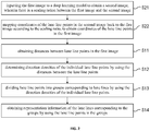
- FIG. 1 shows a flowchart of a lane line processing method according to an embodiment of the present disclosure. As shown in FIG. 1 , the method may include:
- pixel points in the first image may be classified into pixel points of lane lines, which may be referred to as lane line points. Pixel points other than the lane line points in the first image may be referred to as non-lane line points.
- step S11 includes: calculating distances between lane line points according to coordinates of the lane line points in the first image.
- a distance matrix is generated by using the distances between lane line points, where an element in the distance matrix represents a distance between two lane line points in the first image.
- the distance matrix is calculated first, so that it is possible to use the elements in the distance matrix directly when calculating the direction densities, thereby realizing a simple and quick calculation.
- the distances between every two lane line points in an original image can be calculated to form a distance matrix. Assuming that there are N lane line points in the original image, the size of the distance matrix is then N ⁇ N.
- the element e ij in the distance matrix can represent the Euclidean distance between the two lane line points i and j. It is noted that other methods, such as the block distance method, can also be used to calculate elements in the distance matrix.
- the method further includes:
- the present embodiment can be used to post-process predicted output of a deep learning model.
- the deep learning model can be constructed by using a neural network, and certain sample images are used for training so that a confidence, which indicates that individual pixel points in the network output image belong to lane lines, can be obtained by using the deep learning model.
- a confidence threshold is used for a classification. For example, a pixel point with a confidence greater than the threshold can be determined as a lane line point, and a pixel point with a confidence less than or equal to the threshold can be determined as a non-lane line point, etc.
- the identification results can be also used for continuous self-learning so as to optimize the model.
- a 2D image (an original image, i.e., a first image) such as a captured road image or the like can be scaled down by using the deep learning model, and the pixel points in the scaled-down image are classified (0: non-lane line point; 1: lane line point).
- the model can also provide the position of its predicted target point in a network output image (i.e., a second image). Then, coordinates of lane line points in the network output image are mapped back to the original image.
- step S12 further includes:
- the direction density of each of the lane line points in the image can be calculated.
- the direction density can indicate the possibility that a lane line point approaches other lane line points in a certain direction.
- the first threshold and the second threshold may be set with reference to parameters such as the size of the first image, the number of lane line points in the image, and the like.
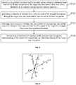
- K neighbor points Pnb_i may be selected from the distance matrix, wherein the distance from each of the K neighbor points to the target lane line point P is less than the first threshold T1.
- each element at the row corresponding to the point P is extracted from the distance matrix. If the extracted element is smaller than the first threshold T1 and the element represents the distance from the point P to the point P1, it can be determined that the point P1 is one neighbor point of the point P.
- all neighbor points of the point P can be determined by extracting the elements at the row and the column corresponding to the point P from the distance matrix. With the size of the first threshold T1 being different, the number of neighbor points may vary.
- a straight line is determined by using the point P and its neighbor points Pnb_i, and the distances from other lane line points to the straight line are calculated.
- the number of the lane line points are determined, wherein the distance from one of the lane line points to the straight line is smaller than the second threshold value T2.
- the maximum of the numbers is taken as the direction density of the point P.
- This line can represent the direction of the point P.
- Each of the lane line points with the distance to the straight line being less than T2 is a relevant point of the straight line, and the relevant points approach the point P along the direction of the straight line. For example, as shown in FIG.
- each small circle represents one lane line point
- the three points with distances from them to P being less than T1 are P1, P2, and P3, where the straight line L1 is determined by using P and P1, the straight line L2 is determined by using P and P2, and the straight line L3 is determined by using P and P3.
- the number of lane line points with the distance from it to L1 being less than the threshold value T2 is 3, the number of lane line points with the distance from it to L2 being less than the threshold value T2 is 4, and the number of lane line points with the distance from it to L3 being less than the threshold value T2 is 5. Because 5 is the largest one in the numbers of the lane line points, it is determined as the direction density of the point P.
- step S13 includes:
- step S132 may include: selecting M lane line points from the first image, wherein a distance from each of the M lane line points to the candidate lane line point is less than a third threshold, M is a positive integer greater than or equal to 1; and determining lane line points belonging to the one of the groups according to the direction densities of the M lane line points.
- the determination of lane line points belonging to the one of the groups according to the direction densities of the M lane line points can be completed in many ways.
- a lane line point having the maximum direction density among the M lane line points is determined as the lane line point belonging to the one of the groups.
- relevant lane line points of a straight line corresponding to a direction density of the candidate lane line point are obtained from the M lane line points.
- the distance from each of the relevant points to the straight line is less than a second threshold.
- a point having the maximum direction density is selected from the obtained relevant lane line points as the lane line point belonging to the one of the groups.
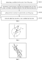
- a candidate lane line point P is selected, and a lane line point Q. having the maximum direction density is selected from the lane line points with the distances from them to the point P being less than the threshold T3 (assuming T3 is 100 pixels).
- the point Q is determined as a new candidate lane line point, and points that satisfy the same condition are selected until no point satisfying the same condition is determined. All points determined by this way are divided into one group. This grouping process is repeated until all lane line points are processed. In this way, a certain number of groups of points can be obtained. For example, as shown in FIG. 6 , each small circle represents a lane line point, and it is assumed that the candidate lane line point P has a direction density of 5.
- a broken line block indicates a region in which the pixel points with the distance from them to the point P being less than the threshold T3 are located.
- the direction density of each lane line point in this region can be calculated by using the method shown in FIG. 4 . Assuming that the direction densities of a plurality of lane line points in the region are 2, 1, 3 and 4 respectively, the point Q. having the maximum direction density (the direction density being 4) is selected. In addition, in combination with the direction of the point P, the point having the maximum direction density can also be selected from the relevant points (with the distance from them to the straight line in FIG. 6 being less than the threshold T2) of the straight line (i.e., the direction of P) corresponding to the direction density of the point P in the region of FIG. 4 .
- the method further includes: merging the lane line points in one of the groups. Then, the merged groups are taken as the final grouping result.
- adjacent groups can be merged by using the principle of spatial adjacency between groups.
- merging examples of which are given below:
- step S14 includes: selecting, for each group, a plurality of lane line points; and performing polynomial fitting on coordinates of the selected plurality of lane line points in the first image, to obtain a polynomial curve of a lane line corresponding to the group.
- the given polynomial is only an example rather than being limiting, and other forms of polynomials can be used as required.
- step S14 further includes: determining coordinates of start points and/or coordinates of end points of the lane line by using the polynomial curve of the lane line.
- the start point and the end point of the lane line can be determined according to the curve. Specifically, in combination with the coordinates of the lane line points in the group and the curve of the lane line corresponding to the group, the start point and the end point information can be determined by using the minimum and the maximum of y (and/or x) among these points.
- a curve L1 is obtained by fitting a certain group, wherein the coordinate of the start point A of L1 is determined by using the minimum of y (and/or x) in the group, and the coordinate of the end point B of L1 is determined by using the maximum and the minimum of y (and/or x).
- a curve L2 is obtained by fitting a certain group, wherein the coordinate of the start point C of L2 is determined by using the minimum of x (the maximum value of y) in the group, and the coordinate of the end point D of L2 is determined by using the maximum of x (the minimum value of y) in the group.
- a curve L3 is obtained by fitting a certain group, wherein the coordinate of the start point E of L3 is determined by using the minimum of y in the group, and the coordinate of the end point F of L3 is determined by using the maximum of y.
- lane line points in an image are divided into groups, the obtained groups are then more accurate, and thus the lane lines obtained by fitting are accurate, are not susceptible to image quality, and have high robustness.
- FIG. 9 is a block diagram showing a structure of a lane line processing device according to an embodiment of the present disclosure. As shown in FIG. 9 , the device may include:
- the device further includes:
- the direction density module 72 is further configured to:
- the grouping module 73 is further configured to:
- the determination of lane line points belonging to the one of the groups according to the direction densities of the M lane line points can be completed in many ways.
- a lane line point having the maximum direction density among the M lane line points is determined as the lane line point belonging to the one of the groups.
- relevant lane line points of a straight line corresponding to a direction density of the candidate lane line point are obtained from the M lane line points.
- the distance from each of the relevant points to the straight line is less than a second threshold.
- a point having the maximum direction density is selected from the obtained relevant lane line points as the lane line point belonging to the one of the groups.
- the lane line representing module 74 includes: a fitting sub-module 741, configured to select, for each group, a plurality of lane line points; and performing polynomial fitting on coordinates of the selected plurality of lane line points in the first image, to obtain a polynomial curve of a lane line corresponding to the group.
- the lane line representing module 74 further includes: a start and end point sub-module 742, configured to determine coordinates of start points and/or coordinates of end points of the lane line by using the polynomial curve of the lane line.
- the device further includes: a merging module 83, configured to merge the lane line points in one of the groups.
- the distance obtaining module 71 includes:
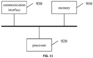
- FIG. 11 is a block diagram showing a structure of a lane line processing device according to an embodiment of the present disclosure.
- the device includes a memory 910 and a processor 920, wherein a computer program that can run on the processor 920 is stored in the memory 910.
- the processor 920 executes the computer program to implement the lane line processing method according to the above embodiments.
- the number of the memory 910 and the processor 920 may each be one or more.
- the device/apparatus/terminal/server further includes: a communication interface 930, configured to communicate with an external device to perform data interaction and transmission.
- the memory 910 may include a high-speed RAM memory, or may also include a non-volatile memory, such as at least one disk memory.
- the bus may be an industry standard architecture (ISA) bus, a peripheral component interconnect (PCI) bus, an extended industry standard architecture (EISA) bus, or the like.
- ISA industry standard architecture
- PCI peripheral component interconnect
- EISA extended industry standard architecture
- the bus may be categorized into an address bus, a data bus, a control bus or the like. For ease of illustration, only one bold line is shown in FIG. 11 to represent the bus, but it does not mean that there is only one bus or only one type of bus.
- the memory 910, the processor 920 and the communication interface 930 are integrated on one chip, then the memory 910, the processor 920 and the communication interface 930 can complete mutual communication through an internal interface.
- a non-volatile computer readable storage medium having a computer program stored thereon which, when executed by a processor, implements the method described in any one of the above embodiments.
- first and second are used for descriptive purposes only, and are not to be construed as indicating or implying relative importance or implicitly indicating the number of recited technical features.
- a feature defined with “first” and “second” may include at least one said feature, either explicitly or implicitly.
- the meaning of "a plurality” is two or more than two, unless otherwise explicitly or specifically indicated.
- the logics and/or steps represented in the flowcharts or otherwise described herein for example may be considered as an ordered list of executable instructions for implementing logical functions. They can be specifically embodied in any computer readable medium for use by an instruction execution system, apparatus or device (e.g., a computer-based system, a system including a processor, or another system that can obtain instructions from the instruction execution system, apparatus or device and execute these instructions) or for use in conjunction with the instruction execution system, apparatus or device.
- "computer readable medium” can be any means that can contain, store, communicate, propagate or transmit programs for use by an instruction execution system, apparatus or device or for use in conjunction with the instruction execution system, apparatus or device.
- computer readable storage medium at least include: electrical connection parts (electronic devices) having one or more wires, portable computer disk cartridges (magnetic devices), random access memory (RAM), read only memory (ROM), erasable programmable read-only memory (EPROM or flash memory), fiber optic devices, and portable read only memory (CDROM).
- the computer-readable storage medium may even be a paper or other suitable medium on which the programs can be printed. This is because for example the paper or other medium can be optically scanned, followed by editing, interpretation or, if necessary, other suitable ways of processing so as to obtain the programs electronically, which are then stored in a computer memory.
- individual functional units in various embodiments of the present disclosure may be integrated in one processing module, or individual units may also exist physically and independently, or two or more units may also be integrated in one module.
- the above integrated module can be implemented in the form of hardware or in the form of a software functional module.
- the integrated module may also be stored in a non-volatile computer readable storage medium if it is implemented in the form of a software function module and sold or used as a stand-alone product.
- the storage medium may be a read-only memory, a magnetic disk or an optical disk, etc.
Landscapes
- Engineering & Computer Science (AREA)
- Physics & Mathematics (AREA)
- Theoretical Computer Science (AREA)
- General Physics & Mathematics (AREA)
- Mathematical Physics (AREA)
- Computer Vision & Pattern Recognition (AREA)
- Software Systems (AREA)
- Data Mining & Analysis (AREA)
- General Engineering & Computer Science (AREA)
- Computing Systems (AREA)
- Multimedia (AREA)
- Evolutionary Computation (AREA)
- Artificial Intelligence (AREA)
- Mathematical Analysis (AREA)
- Computational Mathematics (AREA)
- Pure & Applied Mathematics (AREA)
- Mathematical Optimization (AREA)
- Medical Informatics (AREA)
- Databases & Information Systems (AREA)
- Health & Medical Sciences (AREA)
- Life Sciences & Earth Sciences (AREA)
- Biomedical Technology (AREA)
- Biophysics (AREA)
- Computational Linguistics (AREA)
- General Health & Medical Sciences (AREA)
- Molecular Biology (AREA)
- Algebra (AREA)
- Image Analysis (AREA)
- Traffic Control Systems (AREA)
Applications Claiming Priority (1)
| Application Number | Priority Date | Filing Date | Title |
|---|---|---|---|
| CN201811025492.4A CN109117825B (zh) | 2018-09-04 | 2018-09-04 | 车道线处理方法和装置 |
Publications (2)
| Publication Number | Publication Date |
|---|---|
| EP3620964A1 true EP3620964A1 (de) | 2020-03-11 |
| EP3620964B1 EP3620964B1 (de) | 2023-08-30 |
Family
ID=64860619
Family Applications (1)
| Application Number | Title | Priority Date | Filing Date |
|---|---|---|---|
| EP19187440.3A Active EP3620964B1 (de) | 2018-09-04 | 2019-07-19 | Fahrspurlinienverarbeitungsverfahren und -vorrichtung |
Country Status (4)
| Country | Link |
|---|---|
| US (1) | US11113546B2 (de) |
| EP (1) | EP3620964B1 (de) |
| JP (1) | JP6802331B2 (de) |
| CN (1) | CN109117825B (de) |
Families Citing this family (18)
| Publication number | Priority date | Publication date | Assignee | Title |
|---|---|---|---|---|
| JP6918425B2 (ja) * | 2017-11-09 | 2021-08-11 | 株式会社Mobility Technologies | 撮影画像に含まれる境界線を検出するための装置、方法、及びプログラム |
| US10311338B1 (en) * | 2018-09-15 | 2019-06-04 | StradVision, Inc. | Learning method, learning device for detecting lanes on the basis of CNN and testing method, testing device using the same |
| TWI694019B (zh) * | 2019-06-05 | 2020-05-21 | 國立中正大學 | 車道線偵測與追蹤方法 |
| CN110796066B (zh) * | 2019-10-26 | 2022-09-20 | 武汉中海庭数据技术有限公司 | 一种车道线组构建方法及装置 |
| US11100344B2 (en) * | 2019-11-21 | 2021-08-24 | GM Global Technology Operations LLC | Image-based three-dimensional lane detection |
| CN111191619B (zh) * | 2020-01-02 | 2023-09-05 | 北京百度网讯科技有限公司 | 车道线虚线段的检测方法、装置、设备和可读存储介质 |
| CN114264310B (zh) * | 2020-09-14 | 2024-06-21 | 阿里巴巴集团控股有限公司 | 定位及导航方法、装置、电子设备、计算机存储介质 |
| CN112183415B (zh) * | 2020-09-30 | 2024-07-16 | 上汽通用五菱汽车股份有限公司 | 车道线处理方法、车辆和可读存储介质 |
| CN112381034A (zh) * | 2020-11-25 | 2021-02-19 | 上海眼控科技股份有限公司 | 一种车道线检测方法、装置、设备及存储介质 |
| CN112240772B (zh) * | 2020-12-16 | 2021-09-28 | 北京赛目科技有限公司 | 一种车道线生成方法及装置 |
| CN115049578A (zh) * | 2021-03-08 | 2022-09-13 | 华为技术有限公司 | 一种车道线的属性检测方法与装置 |
| KR102499334B1 (ko) * | 2021-06-28 | 2023-02-14 | (주)뷰런테크놀로지 | 라이다 센서를 이용하여 차선을 검출하는 방법 및 상기 방법을 수행하는 차선 검출 장치 |
| CN113239905B (zh) * | 2021-07-09 | 2021-09-21 | 新石器慧通(北京)科技有限公司 | 车道线简化方法、装置、电子设备及存储介质 |
| CN113537100B (zh) * | 2021-07-22 | 2022-03-22 | 元橡科技(苏州)有限公司 | 一种车辆辅助驾驶系统、车道线时空拟合的系统和方法、fpga芯片 |
| US12454264B2 (en) * | 2022-09-02 | 2025-10-28 | Autobrains Technologies Ltd | Polynomial prediction of road lane metadata |
| CN115828575A (zh) * | 2022-11-28 | 2023-03-21 | 重庆长安汽车股份有限公司 | 一种基于道格算法的车道线拟合的方法、装置及存储介质 |
| CN115830565B (zh) * | 2022-12-20 | 2026-01-02 | 合肥疆程技术有限公司 | 一种车道线的拟合方法、电子设备及汽车 |
| CN115631479B (zh) * | 2022-12-22 | 2023-03-14 | 北京钢铁侠科技有限公司 | 深度学习智能车车道巡线优化方法 |
Family Cites Families (35)
| Publication number | Priority date | Publication date | Assignee | Title |
|---|---|---|---|---|
| JP4638369B2 (ja) * | 2006-03-28 | 2011-02-23 | 富士重工業株式会社 | 車線位置検出装置 |
| US20090232388A1 (en) | 2008-03-12 | 2009-09-17 | Harris Corporation | Registration of 3d point cloud data by creation of filtered density images |
| CN103258338A (zh) | 2012-02-16 | 2013-08-21 | 克利特股份有限公司 | 利用真实数据来驱动仿真的虚拟环境的方法和系统 |
| CN102663196B (zh) | 2012-04-17 | 2014-04-16 | 中南大学 | 一种基于虚拟现实的汽车起重机吊装仿真方法 |
| US9082014B2 (en) * | 2013-03-14 | 2015-07-14 | The Nielsen Company (Us), Llc | Methods and apparatus to estimate demography based on aerial images |
| CN104376297B (zh) * | 2013-08-12 | 2017-06-23 | 株式会社理光 | 道路上的线型指示标志的检测方法和装置 |
| CN103914830B (zh) * | 2014-02-22 | 2017-02-01 | 小米科技有限责任公司 | 直线检测方法和装置 |
| CN104899855A (zh) | 2014-03-06 | 2015-09-09 | 株式会社日立制作所 | 三维障碍物检测方法和装置 |
| CN104933856B (zh) * | 2014-03-17 | 2017-08-25 | 径卫视觉科技(上海)有限公司 | 道路路况实时评估系统及方法 |
| CN104020674B (zh) | 2014-04-21 | 2017-01-25 | 华南农业大学 | 车辆Bug避障算法的Matlab仿真可视化平台 |
| CN104183014B (zh) | 2014-08-13 | 2017-01-18 | 浙江大学 | 一种面向城市增强现实的高融合度信息标注方法 |
| KR101687073B1 (ko) | 2014-10-22 | 2016-12-15 | 주식회사 만도 | 터널 높이 추정 장치 및 터널 높이 추정 방법 |
| CN104457569B (zh) | 2014-11-27 | 2017-06-16 | 大连理工大学 | 一种大型复合板材几何参数视觉测量方法 |
| CN104766058B (zh) * | 2015-03-31 | 2018-04-27 | 百度在线网络技术(北京)有限公司 | 一种获取车道线的方法和装置 |
| CN104950883A (zh) | 2015-05-14 | 2015-09-30 | 西安电子科技大学 | 一种基于距离网格地图的移动机器人路径规划方法 |
| TWI630132B (zh) | 2015-06-04 | 2018-07-21 | 國立虎尾科技大學 | 3D animation car accident scene reconstruction method |
| CN105046235B (zh) * | 2015-08-03 | 2018-09-07 | 百度在线网络技术(北京)有限公司 | 车道线的识别建模方法和装置、识别方法和装置 |
| US20170092000A1 (en) | 2015-09-25 | 2017-03-30 | Moshe Schwimmer | Method and system for positioning a virtual object in a virtual simulation environment |
| JP6464075B2 (ja) | 2015-11-11 | 2019-02-06 | 日本電信電話株式会社 | What−ifシミュレーション装置、方法、及びプログラム |
| WO2017095817A1 (en) | 2015-11-30 | 2017-06-08 | Luminar Technologies, Inc. | Lidar system with distributed laser and multiple sensor heads and pulsed laser for lidar system |
| CN105761308B (zh) | 2016-02-29 | 2018-09-07 | 武汉大学 | 一种地面LiDAR和影像数据融合的遮挡区域建筑物立面重建方法 |
| CN105844600B (zh) | 2016-04-27 | 2018-03-16 | 北京航空航天大学 | 一种空间目标三维点云光顺去噪方法 |
| CN107818293A (zh) | 2016-09-14 | 2018-03-20 | 北京百度网讯科技有限公司 | 用于处理点云数据的方法和装置 |
| CN106462757B (zh) * | 2016-09-26 | 2019-09-06 | 深圳市锐明技术股份有限公司 | 一种成对车道线的快速检测方法和装置 |
| JP6548690B2 (ja) | 2016-10-06 | 2019-07-24 | 株式会社アドバンスド・データ・コントロールズ | シミュレーションシステム、シミュレーションプログラム及びシミュレーション方法 |
| RO132599A2 (ro) | 2016-11-23 | 2018-05-30 | Centrul It Pentru Ştiinţă Şi Tehnologie S.R.L. | Echipament modular pentru inspecţia drumurilor rutiere, incluzând carosabilul şi zona adiacentă, destinat pentru a fi montat pe vehicule nespecializate |
| CN106599832A (zh) | 2016-12-09 | 2017-04-26 | 重庆邮电大学 | 一种基于卷积神经网络的多类障碍物检测与识别方法 |
| CN106919908B (zh) | 2017-02-10 | 2020-07-28 | 百度在线网络技术(北京)有限公司 | 障碍物识别方法及装置、计算机设备及可读介质 |
| CN108492356A (zh) | 2017-02-13 | 2018-09-04 | 苏州宝时得电动工具有限公司 | 增强现实系统及其控制方法 |
| CN107103627B (zh) * | 2017-04-27 | 2020-12-11 | 深圳市天双科技有限公司 | 一种基于车道线的汽车全景摄像头外部参数标定方法 |
| CN107657237B (zh) | 2017-09-28 | 2020-03-31 | 东南大学 | 基于深度学习的汽车碰撞检测方法及系统 |
| CN107678306B (zh) | 2017-10-09 | 2021-04-16 | 驭势(上海)汽车科技有限公司 | 动态场景信息录制和仿真回放方法、装置、设备及介质 |
| CN107832806A (zh) | 2017-12-06 | 2018-03-23 | 四川知创空间孵化器管理有限公司 | 一种车牌类型判别方法和系统 |
| CN107993512A (zh) | 2018-01-03 | 2018-05-04 | 深圳市欣横纵技术股份有限公司 | 一种核安保Table Top Tool系统及使用方法 |
| CN108256506B (zh) | 2018-02-14 | 2020-11-24 | 北京市商汤科技开发有限公司 | 一种视频中物体检测方法及装置、计算机存储介质 |
-
2018
- 2018-09-04 CN CN201811025492.4A patent/CN109117825B/zh active Active
-
2019
- 2019-07-10 JP JP2019128139A patent/JP6802331B2/ja not_active Expired - Fee Related
- 2019-07-19 EP EP19187440.3A patent/EP3620964B1/de active Active
- 2019-07-24 US US16/521,028 patent/US11113546B2/en active Active
Non-Patent Citations (1)
| Title |
|---|
| XIAOHU LU ET AL: "PAIRWISE LINKAGE FOR POINT CLOUD SEGMENTATION", ISPRS ANNALS OF PHOTOGRAMMETRY, REMOTE SENSING AND SPATIAL INFORMATION SCIENCES, vol. III-3, 3 June 2016 (2016-06-03), pages 201 - 208, XP055647625, DOI: 10.5194/isprsannals-III-3-201-2016 * |
Also Published As
| Publication number | Publication date |
|---|---|
| EP3620964B1 (de) | 2023-08-30 |
| JP2020038624A (ja) | 2020-03-12 |
| CN109117825A (zh) | 2019-01-01 |
| US11113546B2 (en) | 2021-09-07 |
| CN109117825B (zh) | 2020-01-17 |
| US20200074189A1 (en) | 2020-03-05 |
| JP6802331B2 (ja) | 2020-12-16 |
Similar Documents
| Publication | Publication Date | Title |
|---|---|---|
| EP3620964A1 (de) | Fahrspurlinienverarbeitungsverfahren und -vorrichtung | |
| EP3617938B1 (de) | Fahrspurlinienverarbeitungsverfahren und -vorrichtung | |
| CN109426801B (zh) | 一种车道线实例检测方法和装置 | |
| US20250157236A1 (en) | Object detection method and apparatus, and computer-readable storage medium and unmanned vehicle | |
| US10984588B2 (en) | Obstacle distribution simulation method and device based on multiple models, and storage medium | |
| US11100341B2 (en) | Lane line tracking method and device | |
| JP5538868B2 (ja) | 画像処理装置、その画像処理方法及びプログラム | |
| US11341297B2 (en) | Obstacle distribution simulation method, device and terminal based on a probability graph | |
| CN111310746A (zh) | 文本行检测方法、模型训练方法、装置、服务器及介质 | |
| CN110705385A (zh) | 一种障碍物角度的检测方法、装置、设备及介质 | |
| CN109840463B (zh) | 一种车道线识别方法和装置 | |
| CN112381034A (zh) | 一种车道线检测方法、装置、设备及存储介质 | |
| Al Mamun et al. | Efficient lane marking detection using deep learning technique with differential and cross-entropy loss. | |
| KR20230009151A (ko) | 차량용 객체 인식 신경망의 학습을 위한 학습 데이터 구축 방법 및 그 장치 | |
| CN114820679A (zh) | 图像标注方法、装置、电子设备和存储介质 | |
| CN114529514B (zh) | 基于图结构的深度数据质量评价方法及装置 | |
| CN112750124B (zh) | 模型生成、图像分割方法、装置、电子设备及存储介质 | |
| EP2631813A1 (de) | Verfahren und vorrichtung zur beseitigung von rissen in seiten | |
| CN112784737B (zh) | 结合像素分割和线段锚的文本检测方法、系统及装置 | |
| CN109919046B (zh) | 一种基于关系特征的三维点云特征学习方法和装置 | |
| US10373004B1 (en) | Method and device for detecting lane elements to plan the drive path of autonomous vehicle by using a horizontal filter mask, wherein the lane elements are unit regions including pixels of lanes in an input image | |
| KR20230022756A (ko) | 차량용 객체 인식 신경망의 학습을 위한 학습 데이터 구축 방법 및 그 장치 | |
| EP4625362A1 (de) | Verfahren und vorrichtung zur erkennung einer fahrspurlinienkreuzung, vorrichtung und speichermedium | |
| US20250014330A1 (en) | Method for extracting an intersection area from a segmentation mask | |
| JP7066580B2 (ja) | 画像処理装置 |
Legal Events
| Date | Code | Title | Description |
|---|---|---|---|
| PUAI | Public reference made under article 153(3) epc to a published international application that has entered the european phase |
Free format text: ORIGINAL CODE: 0009012 |
|
| STAA | Information on the status of an ep patent application or granted ep patent |
Free format text: STATUS: REQUEST FOR EXAMINATION WAS MADE |
|
| 17P | Request for examination filed |
Effective date: 20190719 |
|
| AK | Designated contracting states |
Kind code of ref document: A1 Designated state(s): AL AT BE BG CH CY CZ DE DK EE ES FI FR GB GR HR HU IE IS IT LI LT LU LV MC MK MT NL NO PL PT RO RS SE SI SK SM TR |
|
| AX | Request for extension of the european patent |
Extension state: BA ME |
|
| STAA | Information on the status of an ep patent application or granted ep patent |
Free format text: STATUS: EXAMINATION IS IN PROGRESS |
|
| 17Q | First examination report despatched |
Effective date: 20211018 |
|
| RAP1 | Party data changed (applicant data changed or rights of an application transferred) |
Owner name: APOLLO INTELLIGENT DRIVING TECHNOLOGY (BEIJING) CO., LTD. |
|
| REG | Reference to a national code |
Ref legal event code: R079 Ref country code: DE Ref document number: 602019035978 Country of ref document: DE Free format text: PREVIOUS MAIN CLASS: G06K0009000000 Ipc: G06T0007130000 |
|
| RIC1 | Information provided on ipc code assigned before grant |
Ipc: G06V 20/56 20220101ALI20230130BHEP Ipc: G06T 7/181 20170101ALI20230130BHEP Ipc: G06T 7/13 20170101AFI20230130BHEP |
|
| GRAP | Despatch of communication of intention to grant a patent |
Free format text: ORIGINAL CODE: EPIDOSNIGR1 |
|
| STAA | Information on the status of an ep patent application or granted ep patent |
Free format text: STATUS: GRANT OF PATENT IS INTENDED |
|
| INTG | Intention to grant announced |
Effective date: 20230330 |
|
| GRAS | Grant fee paid |
Free format text: ORIGINAL CODE: EPIDOSNIGR3 |
|
| GRAA | (expected) grant |
Free format text: ORIGINAL CODE: 0009210 |
|
| STAA | Information on the status of an ep patent application or granted ep patent |
Free format text: STATUS: THE PATENT HAS BEEN GRANTED |
|
| AK | Designated contracting states |
Kind code of ref document: B1 Designated state(s): AL AT BE BG CH CY CZ DE DK EE ES FI FR GB GR HR HU IE IS IT LI LT LU LV MC MK MT NL NO PL PT RO RS SE SI SK SM TR |
|
| REG | Reference to a national code |
Ref country code: GB Ref legal event code: FG4D |
|
| REG | Reference to a national code |
Ref country code: CH Ref legal event code: EP |
|
| REG | Reference to a national code |
Ref country code: DE Ref legal event code: R096 Ref document number: 602019035978 Country of ref document: DE |
|
| REG | Reference to a national code |
Ref country code: IE Ref legal event code: FG4D |
|
| P01 | Opt-out of the competence of the unified patent court (upc) registered |
Effective date: 20231117 |
|
| REG | Reference to a national code |
Ref country code: LT Ref legal event code: MG9D |
|
| REG | Reference to a national code |
Ref country code: NL Ref legal event code: MP Effective date: 20230830 |
|
| REG | Reference to a national code |
Ref country code: AT Ref legal event code: MK05 Ref document number: 1606409 Country of ref document: AT Kind code of ref document: T Effective date: 20230830 |
|
| PG25 | Lapsed in a contracting state [announced via postgrant information from national office to epo] |
Ref country code: GR Free format text: LAPSE BECAUSE OF FAILURE TO SUBMIT A TRANSLATION OF THE DESCRIPTION OR TO PAY THE FEE WITHIN THE PRESCRIBED TIME-LIMIT Effective date: 20231201 |
|
| PG25 | Lapsed in a contracting state [announced via postgrant information from national office to epo] |
Ref country code: IS Free format text: LAPSE BECAUSE OF FAILURE TO SUBMIT A TRANSLATION OF THE DESCRIPTION OR TO PAY THE FEE WITHIN THE PRESCRIBED TIME-LIMIT Effective date: 20231230 |
|
| PG25 | Lapsed in a contracting state [announced via postgrant information from national office to epo] |
Ref country code: SE Free format text: LAPSE BECAUSE OF FAILURE TO SUBMIT A TRANSLATION OF THE DESCRIPTION OR TO PAY THE FEE WITHIN THE PRESCRIBED TIME-LIMIT Effective date: 20230830 Ref country code: RS Free format text: LAPSE BECAUSE OF FAILURE TO SUBMIT A TRANSLATION OF THE DESCRIPTION OR TO PAY THE FEE WITHIN THE PRESCRIBED TIME-LIMIT Effective date: 20230830 Ref country code: NO Free format text: LAPSE BECAUSE OF FAILURE TO SUBMIT A TRANSLATION OF THE DESCRIPTION OR TO PAY THE FEE WITHIN THE PRESCRIBED TIME-LIMIT Effective date: 20231130 Ref country code: LV Free format text: LAPSE BECAUSE OF FAILURE TO SUBMIT A TRANSLATION OF THE DESCRIPTION OR TO PAY THE FEE WITHIN THE PRESCRIBED TIME-LIMIT Effective date: 20230830 Ref country code: LT Free format text: LAPSE BECAUSE OF FAILURE TO SUBMIT A TRANSLATION OF THE DESCRIPTION OR TO PAY THE FEE WITHIN THE PRESCRIBED TIME-LIMIT Effective date: 20230830 Ref country code: IS Free format text: LAPSE BECAUSE OF FAILURE TO SUBMIT A TRANSLATION OF THE DESCRIPTION OR TO PAY THE FEE WITHIN THE PRESCRIBED TIME-LIMIT Effective date: 20231230 Ref country code: HR Free format text: LAPSE BECAUSE OF FAILURE TO SUBMIT A TRANSLATION OF THE DESCRIPTION OR TO PAY THE FEE WITHIN THE PRESCRIBED TIME-LIMIT Effective date: 20230830 Ref country code: GR Free format text: LAPSE BECAUSE OF FAILURE TO SUBMIT A TRANSLATION OF THE DESCRIPTION OR TO PAY THE FEE WITHIN THE PRESCRIBED TIME-LIMIT Effective date: 20231201 Ref country code: FI Free format text: LAPSE BECAUSE OF FAILURE TO SUBMIT A TRANSLATION OF THE DESCRIPTION OR TO PAY THE FEE WITHIN THE PRESCRIBED TIME-LIMIT Effective date: 20230830 Ref country code: AT Free format text: LAPSE BECAUSE OF FAILURE TO SUBMIT A TRANSLATION OF THE DESCRIPTION OR TO PAY THE FEE WITHIN THE PRESCRIBED TIME-LIMIT Effective date: 20230830 |
|
| PG25 | Lapsed in a contracting state [announced via postgrant information from national office to epo] |
Ref country code: PL Free format text: LAPSE BECAUSE OF FAILURE TO SUBMIT A TRANSLATION OF THE DESCRIPTION OR TO PAY THE FEE WITHIN THE PRESCRIBED TIME-LIMIT Effective date: 20230830 Ref country code: NL Free format text: LAPSE BECAUSE OF FAILURE TO SUBMIT A TRANSLATION OF THE DESCRIPTION OR TO PAY THE FEE WITHIN THE PRESCRIBED TIME-LIMIT Effective date: 20230830 |
|
| PG25 | Lapsed in a contracting state [announced via postgrant information from national office to epo] |
Ref country code: ES Free format text: LAPSE BECAUSE OF FAILURE TO SUBMIT A TRANSLATION OF THE DESCRIPTION OR TO PAY THE FEE WITHIN THE PRESCRIBED TIME-LIMIT Effective date: 20230830 |
|
| PG25 | Lapsed in a contracting state [announced via postgrant information from national office to epo] |
Ref country code: SM Free format text: LAPSE BECAUSE OF FAILURE TO SUBMIT A TRANSLATION OF THE DESCRIPTION OR TO PAY THE FEE WITHIN THE PRESCRIBED TIME-LIMIT Effective date: 20230830 Ref country code: RO Free format text: LAPSE BECAUSE OF FAILURE TO SUBMIT A TRANSLATION OF THE DESCRIPTION OR TO PAY THE FEE WITHIN THE PRESCRIBED TIME-LIMIT Effective date: 20230830 Ref country code: ES Free format text: LAPSE BECAUSE OF FAILURE TO SUBMIT A TRANSLATION OF THE DESCRIPTION OR TO PAY THE FEE WITHIN THE PRESCRIBED TIME-LIMIT Effective date: 20230830 Ref country code: EE Free format text: LAPSE BECAUSE OF FAILURE TO SUBMIT A TRANSLATION OF THE DESCRIPTION OR TO PAY THE FEE WITHIN THE PRESCRIBED TIME-LIMIT Effective date: 20230830 Ref country code: DK Free format text: LAPSE BECAUSE OF FAILURE TO SUBMIT A TRANSLATION OF THE DESCRIPTION OR TO PAY THE FEE WITHIN THE PRESCRIBED TIME-LIMIT Effective date: 20230830 Ref country code: CZ Free format text: LAPSE BECAUSE OF FAILURE TO SUBMIT A TRANSLATION OF THE DESCRIPTION OR TO PAY THE FEE WITHIN THE PRESCRIBED TIME-LIMIT Effective date: 20230830 Ref country code: SK Free format text: LAPSE BECAUSE OF FAILURE TO SUBMIT A TRANSLATION OF THE DESCRIPTION OR TO PAY THE FEE WITHIN THE PRESCRIBED TIME-LIMIT Effective date: 20230830 Ref country code: PT Free format text: LAPSE BECAUSE OF FAILURE TO SUBMIT A TRANSLATION OF THE DESCRIPTION OR TO PAY THE FEE WITHIN THE PRESCRIBED TIME-LIMIT Effective date: 20240102 |
|
| PG25 | Lapsed in a contracting state [announced via postgrant information from national office to epo] |
Ref country code: IT Free format text: LAPSE BECAUSE OF FAILURE TO SUBMIT A TRANSLATION OF THE DESCRIPTION OR TO PAY THE FEE WITHIN THE PRESCRIBED TIME-LIMIT Effective date: 20230830 |
|
| REG | Reference to a national code |
Ref country code: DE Ref legal event code: R097 Ref document number: 602019035978 Country of ref document: DE |
|
| PLBE | No opposition filed within time limit |
Free format text: ORIGINAL CODE: 0009261 |
|
| STAA | Information on the status of an ep patent application or granted ep patent |
Free format text: STATUS: NO OPPOSITION FILED WITHIN TIME LIMIT |
|
| PG25 | Lapsed in a contracting state [announced via postgrant information from national office to epo] |
Ref country code: SI Free format text: LAPSE BECAUSE OF FAILURE TO SUBMIT A TRANSLATION OF THE DESCRIPTION OR TO PAY THE FEE WITHIN THE PRESCRIBED TIME-LIMIT Effective date: 20230830 |
|
| 26N | No opposition filed |
Effective date: 20240603 |
|
| PG25 | Lapsed in a contracting state [announced via postgrant information from national office to epo] |
Ref country code: BG Free format text: LAPSE BECAUSE OF FAILURE TO SUBMIT A TRANSLATION OF THE DESCRIPTION OR TO PAY THE FEE WITHIN THE PRESCRIBED TIME-LIMIT Effective date: 20230830 |
|
| PG25 | Lapsed in a contracting state [announced via postgrant information from national office to epo] |
Ref country code: BG Free format text: LAPSE BECAUSE OF FAILURE TO SUBMIT A TRANSLATION OF THE DESCRIPTION OR TO PAY THE FEE WITHIN THE PRESCRIBED TIME-LIMIT Effective date: 20230830 |
|
| PG25 | Lapsed in a contracting state [announced via postgrant information from national office to epo] |
Ref country code: MC Free format text: LAPSE BECAUSE OF FAILURE TO SUBMIT A TRANSLATION OF THE DESCRIPTION OR TO PAY THE FEE WITHIN THE PRESCRIBED TIME-LIMIT Effective date: 20230830 |
|
| REG | Reference to a national code |
Ref country code: CH Ref legal event code: PL |
|
| PG25 | Lapsed in a contracting state [announced via postgrant information from national office to epo] |
Ref country code: LU Free format text: LAPSE BECAUSE OF NON-PAYMENT OF DUE FEES Effective date: 20240719 |
|
| GBPC | Gb: european patent ceased through non-payment of renewal fee |
Effective date: 20240719 |
|
| PG25 | Lapsed in a contracting state [announced via postgrant information from national office to epo] |
Ref country code: LU Free format text: LAPSE BECAUSE OF NON-PAYMENT OF DUE FEES Effective date: 20240719 |
|
| PG25 | Lapsed in a contracting state [announced via postgrant information from national office to epo] |
Ref country code: CH Free format text: LAPSE BECAUSE OF NON-PAYMENT OF DUE FEES Effective date: 20240731 Ref country code: BE Free format text: LAPSE BECAUSE OF NON-PAYMENT OF DUE FEES Effective date: 20240731 |
|
| PG25 | Lapsed in a contracting state [announced via postgrant information from national office to epo] |
Ref country code: GB Free format text: LAPSE BECAUSE OF NON-PAYMENT OF DUE FEES Effective date: 20240719 |
|
| REG | Reference to a national code |
Ref country code: BE Ref legal event code: MM Effective date: 20240731 |
|
| PGFP | Annual fee paid to national office [announced via postgrant information from national office to epo] |
Ref country code: FR Payment date: 20250603 Year of fee payment: 7 |
|
| PG25 | Lapsed in a contracting state [announced via postgrant information from national office to epo] |
Ref country code: IE Free format text: LAPSE BECAUSE OF NON-PAYMENT OF DUE FEES Effective date: 20240719 |
|
| PGFP | Annual fee paid to national office [announced via postgrant information from national office to epo] |
Ref country code: DE Payment date: 20250722 Year of fee payment: 7 |
|
| PG25 | Lapsed in a contracting state [announced via postgrant information from national office to epo] |
Ref country code: CY Free format text: LAPSE BECAUSE OF FAILURE TO SUBMIT A TRANSLATION OF THE DESCRIPTION OR TO PAY THE FEE WITHIN THE PRESCRIBED TIME-LIMIT; INVALID AB INITIO Effective date: 20190719 |
|
| PG25 | Lapsed in a contracting state [announced via postgrant information from national office to epo] |
Ref country code: HU Free format text: LAPSE BECAUSE OF FAILURE TO SUBMIT A TRANSLATION OF THE DESCRIPTION OR TO PAY THE FEE WITHIN THE PRESCRIBED TIME-LIMIT; INVALID AB INITIO Effective date: 20190719 |