EP3621174A1 - Verfahren und vorrichtung zum laden und entladen - Google Patents
Verfahren und vorrichtung zum laden und entladen Download PDFInfo
- Publication number
- EP3621174A1 EP3621174A1 EP19196020.2A EP19196020A EP3621174A1 EP 3621174 A1 EP3621174 A1 EP 3621174A1 EP 19196020 A EP19196020 A EP 19196020A EP 3621174 A1 EP3621174 A1 EP 3621174A1
- Authority
- EP
- European Patent Office
- Prior art keywords
- node
- coupled
- switch set
- bridge arm
- charging
- Prior art date
- Legal status (The legal status is an assumption and is not a legal conclusion. Google has not performed a legal analysis and makes no representation as to the accuracy of the status listed.)
- Granted
Links
Images




Classifications
-
- B—PERFORMING OPERATIONS; TRANSPORTING
- B60—VEHICLES IN GENERAL
- B60L—PROPULSION OF ELECTRICALLY-PROPELLED VEHICLES; SUPPLYING ELECTRIC POWER FOR AUXILIARY EQUIPMENT OF ELECTRICALLY-PROPELLED VEHICLES; ELECTRODYNAMIC BRAKE SYSTEMS FOR VEHICLES IN GENERAL; MAGNETIC SUSPENSION OR LEVITATION FOR VEHICLES; MONITORING OPERATING VARIABLES OF ELECTRICALLY-PROPELLED VEHICLES; ELECTRIC SAFETY DEVICES FOR ELECTRICALLY-PROPELLED VEHICLES
- B60L53/00—Methods of charging batteries, specially adapted for electric vehicles; Charging stations or on-board charging equipment therefor; Exchange of energy storage elements in electric vehicles
- B60L53/20—Methods of charging batteries, specially adapted for electric vehicles; Charging stations or on-board charging equipment therefor; Exchange of energy storage elements in electric vehicles characterised by converters located in the vehicle
-
- H—ELECTRICITY
- H02—GENERATION; CONVERSION OR DISTRIBUTION OF ELECTRIC POWER
- H02J—ELECTRIC POWER NETWORKS; CIRCUIT ARRANGEMENTS OR SYSTEMS FOR SUPPLYING OR DISTRIBUTING ELECTRIC POWER; SYSTEMS FOR STORING ELECTRIC ENERGY
- H02J7/00—Circuit arrangements for charging or discharging batteries or for supplying loads from batteries
-
- H—ELECTRICITY
- H02—GENERATION; CONVERSION OR DISTRIBUTION OF ELECTRIC POWER
- H02J—ELECTRIC POWER NETWORKS; CIRCUIT ARRANGEMENTS OR SYSTEMS FOR SUPPLYING OR DISTRIBUTING ELECTRIC POWER; SYSTEMS FOR STORING ELECTRIC ENERGY
- H02J9/00—Circuit arrangements for emergency or stand-by power supply, e.g. for emergency lighting
- H02J9/04—Circuit arrangements for emergency or stand-by power supply, e.g. for emergency lighting in which the distribution system is disconnected from the normal source and connected to a standby source
- H02J9/06—Circuit arrangements for emergency or stand-by power supply, e.g. for emergency lighting in which the distribution system is disconnected from the normal source and connected to a standby source with automatic change-over, e.g. UPS systems
-
- H—ELECTRICITY
- H02—GENERATION; CONVERSION OR DISTRIBUTION OF ELECTRIC POWER
- H02M—APPARATUS FOR CONVERSION BETWEEN AC AND AC, BETWEEN AC AND DC, OR BETWEEN DC AND DC, AND FOR USE WITH MAINS OR SIMILAR POWER SUPPLY SYSTEMS; CONVERSION OF DC OR AC INPUT POWER INTO SURGE OUTPUT POWER; CONTROL OR REGULATION THEREOF
- H02M1/00—Details of apparatus for conversion
- H02M1/10—Arrangements incorporating converting means for enabling loads to be operated at will from different kinds of power supplies, e.g. from AC or DC
-
- H—ELECTRICITY
- H02—GENERATION; CONVERSION OR DISTRIBUTION OF ELECTRIC POWER
- H02M—APPARATUS FOR CONVERSION BETWEEN AC AND AC, BETWEEN AC AND DC, OR BETWEEN DC AND DC, AND FOR USE WITH MAINS OR SIMILAR POWER SUPPLY SYSTEMS; CONVERSION OF DC OR AC INPUT POWER INTO SURGE OUTPUT POWER; CONTROL OR REGULATION THEREOF
- H02M3/00—Conversion of DC power input into DC power output
- H02M3/22—Conversion of DC power input into DC power output with intermediate conversion into AC
- H02M3/24—Conversion of DC power input into DC power output with intermediate conversion into AC by static converters
- H02M3/28—Conversion of DC power input into DC power output with intermediate conversion into AC by static converters using discharge tubes with control electrode or semiconductor devices with control electrode to produce the intermediate AC
- H02M3/325—Conversion of DC power input into DC power output with intermediate conversion into AC by static converters using discharge tubes with control electrode or semiconductor devices with control electrode to produce the intermediate AC using devices of a triode or a transistor type requiring continuous application of a control signal
- H02M3/335—Conversion of DC power input into DC power output with intermediate conversion into AC by static converters using discharge tubes with control electrode or semiconductor devices with control electrode to produce the intermediate AC using devices of a triode or a transistor type requiring continuous application of a control signal using semiconductor devices only
- H02M3/33569—Conversion of DC power input into DC power output with intermediate conversion into AC by static converters using discharge tubes with control electrode or semiconductor devices with control electrode to produce the intermediate AC using devices of a triode or a transistor type requiring continuous application of a control signal using semiconductor devices only having several active switching elements
- H02M3/33576—Conversion of DC power input into DC power output with intermediate conversion into AC by static converters using discharge tubes with control electrode or semiconductor devices with control electrode to produce the intermediate AC using devices of a triode or a transistor type requiring continuous application of a control signal using semiconductor devices only having several active switching elements having at least one active switching element at the secondary side of an isolation transformer
- H02M3/33584—Bidirectional converters
-
- H—ELECTRICITY
- H02—GENERATION; CONVERSION OR DISTRIBUTION OF ELECTRIC POWER
- H02M—APPARATUS FOR CONVERSION BETWEEN AC AND AC, BETWEEN AC AND DC, OR BETWEEN DC AND DC, AND FOR USE WITH MAINS OR SIMILAR POWER SUPPLY SYSTEMS; CONVERSION OF DC OR AC INPUT POWER INTO SURGE OUTPUT POWER; CONTROL OR REGULATION THEREOF
- H02M7/00—Conversion of AC power input into DC power output; Conversion of DC power input into AC power output
- H02M7/66—Conversion of AC power input into DC power output; Conversion of DC power input into AC power output with possibility of reversal
- H02M7/68—Conversion of AC power input into DC power output; Conversion of DC power input into AC power output with possibility of reversal by static converters
- H02M7/72—Conversion of AC power input into DC power output; Conversion of DC power input into AC power output with possibility of reversal by static converters using discharge tubes with control electrode or semiconductor devices with control electrode
- H02M7/79—Conversion of AC power input into DC power output; Conversion of DC power input into AC power output with possibility of reversal by static converters using discharge tubes with control electrode or semiconductor devices with control electrode using devices of a triode or transistor type requiring continuous application of a control signal
- H02M7/797—Conversion of AC power input into DC power output; Conversion of DC power input into AC power output with possibility of reversal by static converters using discharge tubes with control electrode or semiconductor devices with control electrode using devices of a triode or transistor type requiring continuous application of a control signal using semiconductor devices only
-
- H—ELECTRICITY
- H03—ELECTRONIC CIRCUITRY
- H03K—PULSE TECHNIQUE
- H03K17/00—Electronic switching or gating, i.e. not by contact-making and –breaking
- H03K17/51—Electronic switching or gating, i.e. not by contact-making and –breaking characterised by the components used
- H03K17/56—Electronic switching or gating, i.e. not by contact-making and –breaking characterised by the components used by the use, as active elements, of semiconductor devices
- H03K17/687—Electronic switching or gating, i.e. not by contact-making and –breaking characterised by the components used by the use, as active elements, of semiconductor devices the devices being field-effect transistors
- H03K17/693—Switching arrangements with several input- or output-terminals, e.g. multiplexers, distributors
-
- H—ELECTRICITY
- H02—GENERATION; CONVERSION OR DISTRIBUTION OF ELECTRIC POWER
- H02J—ELECTRIC POWER NETWORKS; CIRCUIT ARRANGEMENTS OR SYSTEMS FOR SUPPLYING OR DISTRIBUTING ELECTRIC POWER; SYSTEMS FOR STORING ELECTRIC ENERGY
- H02J2105/00—Networks for supplying or distributing electric power characterised by their spatial reach or by the load
- H02J2105/30—Networks for supplying or distributing electric power characterised by their spatial reach or by the load the load networks being external to vehicles, i.e. exchanging power with vehicles
- H02J2105/33—Networks for supplying or distributing electric power characterised by their spatial reach or by the load the load networks being external to vehicles, i.e. exchanging power with vehicles exchanging power with road vehicles
- H02J2105/37—Networks for supplying or distributing electric power characterised by their spatial reach or by the load the load networks being external to vehicles, i.e. exchanging power with vehicles exchanging power with road vehicles exchanging power with electric vehicles [EV] or with hybrid electric vehicles [HEV]
-
- H—ELECTRICITY
- H02—GENERATION; CONVERSION OR DISTRIBUTION OF ELECTRIC POWER
- H02J—ELECTRIC POWER NETWORKS; CIRCUIT ARRANGEMENTS OR SYSTEMS FOR SUPPLYING OR DISTRIBUTING ELECTRIC POWER; SYSTEMS FOR STORING ELECTRIC ENERGY
- H02J2207/00—Details of circuit arrangements for charging or discharging batteries or supplying loads from batteries
- H02J2207/20—Charging or discharging characterised by the power electronics converter
-
- H—ELECTRICITY
- H02—GENERATION; CONVERSION OR DISTRIBUTION OF ELECTRIC POWER
- H02J—ELECTRIC POWER NETWORKS; CIRCUIT ARRANGEMENTS OR SYSTEMS FOR SUPPLYING OR DISTRIBUTING ELECTRIC POWER; SYSTEMS FOR STORING ELECTRIC ENERGY
- H02J7/00—Circuit arrangements for charging or discharging batteries or for supplying loads from batteries
- H02J7/02—Circuit arrangements for charging or discharging batteries or for supplying loads from batteries for charging batteries from AC mains by converters
-
- H—ELECTRICITY
- H02—GENERATION; CONVERSION OR DISTRIBUTION OF ELECTRIC POWER
- H02M—APPARATUS FOR CONVERSION BETWEEN AC AND AC, BETWEEN AC AND DC, OR BETWEEN DC AND DC, AND FOR USE WITH MAINS OR SIMILAR POWER SUPPLY SYSTEMS; CONVERSION OF DC OR AC INPUT POWER INTO SURGE OUTPUT POWER; CONTROL OR REGULATION THEREOF
- H02M1/00—Details of apparatus for conversion
- H02M1/0048—Circuits or arrangements for reducing losses
- H02M1/0054—Transistor switching losses
- H02M1/0058—Transistor switching losses by employing soft switching techniques, i.e. commutation of transistors when applied voltage is zero or when current flow is zero
-
- H—ELECTRICITY
- H02—GENERATION; CONVERSION OR DISTRIBUTION OF ELECTRIC POWER
- H02M—APPARATUS FOR CONVERSION BETWEEN AC AND AC, BETWEEN AC AND DC, OR BETWEEN DC AND DC, AND FOR USE WITH MAINS OR SIMILAR POWER SUPPLY SYSTEMS; CONVERSION OF DC OR AC INPUT POWER INTO SURGE OUTPUT POWER; CONTROL OR REGULATION THEREOF
- H02M1/00—Details of apparatus for conversion
- H02M1/0067—Converter structures employing plural converter units, other than for parallel operation of the units on a single load
- H02M1/007—Plural converter units in cascade
-
- H—ELECTRICITY
- H02—GENERATION; CONVERSION OR DISTRIBUTION OF ELECTRIC POWER
- H02M—APPARATUS FOR CONVERSION BETWEEN AC AND AC, BETWEEN AC AND DC, OR BETWEEN DC AND DC, AND FOR USE WITH MAINS OR SIMILAR POWER SUPPLY SYSTEMS; CONVERSION OF DC OR AC INPUT POWER INTO SURGE OUTPUT POWER; CONTROL OR REGULATION THEREOF
- H02M1/00—Details of apparatus for conversion
- H02M1/0067—Converter structures employing plural converter units, other than for parallel operation of the units on a single load
- H02M1/0074—Plural converter units whose inputs are connected in series
-
- H—ELECTRICITY
- H02—GENERATION; CONVERSION OR DISTRIBUTION OF ELECTRIC POWER
- H02M—APPARATUS FOR CONVERSION BETWEEN AC AND AC, BETWEEN AC AND DC, OR BETWEEN DC AND DC, AND FOR USE WITH MAINS OR SIMILAR POWER SUPPLY SYSTEMS; CONVERSION OF DC OR AC INPUT POWER INTO SURGE OUTPUT POWER; CONTROL OR REGULATION THEREOF
- H02M1/00—Details of apparatus for conversion
- H02M1/36—Means for starting or stopping converters
-
- H—ELECTRICITY
- H02—GENERATION; CONVERSION OR DISTRIBUTION OF ELECTRIC POWER
- H02M—APPARATUS FOR CONVERSION BETWEEN AC AND AC, BETWEEN AC AND DC, OR BETWEEN DC AND DC, AND FOR USE WITH MAINS OR SIMILAR POWER SUPPLY SYSTEMS; CONVERSION OF DC OR AC INPUT POWER INTO SURGE OUTPUT POWER; CONTROL OR REGULATION THEREOF
- H02M3/00—Conversion of DC power input into DC power output
- H02M3/22—Conversion of DC power input into DC power output with intermediate conversion into AC
- H02M3/24—Conversion of DC power input into DC power output with intermediate conversion into AC by static converters
- H02M3/28—Conversion of DC power input into DC power output with intermediate conversion into AC by static converters using discharge tubes with control electrode or semiconductor devices with control electrode to produce the intermediate AC
- H02M3/285—Single converters with a plurality of output stages connected in parallel
-
- H—ELECTRICITY
- H02—GENERATION; CONVERSION OR DISTRIBUTION OF ELECTRIC POWER
- H02M—APPARATUS FOR CONVERSION BETWEEN AC AND AC, BETWEEN AC AND DC, OR BETWEEN DC AND DC, AND FOR USE WITH MAINS OR SIMILAR POWER SUPPLY SYSTEMS; CONVERSION OF DC OR AC INPUT POWER INTO SURGE OUTPUT POWER; CONTROL OR REGULATION THEREOF
- H02M7/00—Conversion of AC power input into DC power output; Conversion of DC power input into AC power output
- H02M7/02—Conversion of AC power input into DC power output without possibility of reversal
- H02M7/04—Conversion of AC power input into DC power output without possibility of reversal by static converters
- H02M7/12—Conversion of AC power input into DC power output without possibility of reversal by static converters using discharge tubes with control electrode or semiconductor devices with control electrode
- H02M7/125—Avoiding or suppressing excessive transient voltages or currents
-
- Y—GENERAL TAGGING OF NEW TECHNOLOGICAL DEVELOPMENTS; GENERAL TAGGING OF CROSS-SECTIONAL TECHNOLOGIES SPANNING OVER SEVERAL SECTIONS OF THE IPC; TECHNICAL SUBJECTS COVERED BY FORMER USPC CROSS-REFERENCE ART COLLECTIONS [XRACs] AND DIGESTS
- Y02—TECHNOLOGIES OR APPLICATIONS FOR MITIGATION OR ADAPTATION AGAINST CLIMATE CHANGE
- Y02T—CLIMATE CHANGE MITIGATION TECHNOLOGIES RELATED TO TRANSPORTATION
- Y02T10/00—Road transport of goods or passengers
- Y02T10/60—Other road transportation technologies with climate change mitigation effect
- Y02T10/70—Energy storage systems for electromobility, e.g. batteries
-
- Y—GENERAL TAGGING OF NEW TECHNOLOGICAL DEVELOPMENTS; GENERAL TAGGING OF CROSS-SECTIONAL TECHNOLOGIES SPANNING OVER SEVERAL SECTIONS OF THE IPC; TECHNICAL SUBJECTS COVERED BY FORMER USPC CROSS-REFERENCE ART COLLECTIONS [XRACs] AND DIGESTS
- Y02—TECHNOLOGIES OR APPLICATIONS FOR MITIGATION OR ADAPTATION AGAINST CLIMATE CHANGE
- Y02T—CLIMATE CHANGE MITIGATION TECHNOLOGIES RELATED TO TRANSPORTATION
- Y02T10/00—Road transport of goods or passengers
- Y02T10/60—Other road transportation technologies with climate change mitigation effect
- Y02T10/7072—Electromobility specific charging systems or methods for batteries, ultracapacitors, supercapacitors or double-layer capacitors
-
- Y—GENERAL TAGGING OF NEW TECHNOLOGICAL DEVELOPMENTS; GENERAL TAGGING OF CROSS-SECTIONAL TECHNOLOGIES SPANNING OVER SEVERAL SECTIONS OF THE IPC; TECHNICAL SUBJECTS COVERED BY FORMER USPC CROSS-REFERENCE ART COLLECTIONS [XRACs] AND DIGESTS
- Y02—TECHNOLOGIES OR APPLICATIONS FOR MITIGATION OR ADAPTATION AGAINST CLIMATE CHANGE
- Y02T—CLIMATE CHANGE MITIGATION TECHNOLOGIES RELATED TO TRANSPORTATION
- Y02T10/00—Road transport of goods or passengers
- Y02T10/80—Technologies aiming to reduce greenhouse gasses emissions common to all road transportation technologies
- Y02T10/92—Energy efficient charging or discharging systems for batteries, ultracapacitors, supercapacitors or double-layer capacitors specially adapted for vehicles
-
- Y—GENERAL TAGGING OF NEW TECHNOLOGICAL DEVELOPMENTS; GENERAL TAGGING OF CROSS-SECTIONAL TECHNOLOGIES SPANNING OVER SEVERAL SECTIONS OF THE IPC; TECHNICAL SUBJECTS COVERED BY FORMER USPC CROSS-REFERENCE ART COLLECTIONS [XRACs] AND DIGESTS
- Y02—TECHNOLOGIES OR APPLICATIONS FOR MITIGATION OR ADAPTATION AGAINST CLIMATE CHANGE
- Y02T—CLIMATE CHANGE MITIGATION TECHNOLOGIES RELATED TO TRANSPORTATION
- Y02T90/00—Enabling technologies or technologies with a potential or indirect contribution to GHG emissions mitigation
- Y02T90/10—Technologies relating to charging of electric vehicles
- Y02T90/14—Plug-in electric vehicles
Definitions
- the present disclosure relates to the technical field of power supply, and in particular, to an apparatus and a method for charging and discharging.
- the aim of the present disclosure is to provide an apparatus and a method for charging and discharging for, at least to some extent, filling the technical blank of a bidirectional vehicle charging and discharging machine compatible with single-phase and three-phase due to limitations and drawbacks of the related art.
- an apparatus for charging and discharging including:
- control module is configured to: when the AC power terminal receives three-phase AC input or sends three-phase AC output, control the first end of the first switch set to be coupled to the third end of the first switch set and the first end of the second switch set to be coupled to the third end of the second switch set; and when the AC power supply terminal receives single-phase AC input or single-phase AC output, control the first end of the first switch set to be coupled to the second end of the first switch set, and control the first end of the second switch set to be disconnected with the third end of the second switch set.
- the apparatus for charging and discharging further includes: a third switch set, coupled to the control module, including a first end and a second end, the first end of the third switch set being coupled to the first center line node, and the second end of the third switch set being coupled to the second center line node.
- the first switch set and the second switch set includes a single-pole double-throw switch, a double-pole double-throw switch, two semiconductor switches or two relays.
- the power conversion stage includes:
- the AC/DC converter and the DC/DC converter are bidirectional converter.
- the DC/DC converter includes a resonant circuit
- the resonant circuit includes a primary circuit, a resonant tank, and a secondary circuit
- both the primary circuit and the secondary circuit are full bridge circuits
- the resonant tank includes a transformer, at least one inductor and at least one capacitor.
- the power conversion stage includes:
- the power conversion stage further includes: a switch bridge arm, in parallel with the second bus capacitor, including a first resistor and a fourth switch set coupled to each other, the fourth switch set being coupled to the control module, and being turned on or turned off in response to a first control signal formed by the control module according to an operation mode of the apparatus for charging and discharging; and a fifth switch set, coupled to the control module, having a first end, a second end and a third end, the first end of the fifth switch set being coupled to the first center line node, the second end of the fifth switch set being coupled to the sixth node or coupled to the sixth node by the third inductor, the third end of the fifth switch set being coupled to the second center line node, and the first end of fifth switch set being selectively coupled to the second end of the fifth switch set or the third end of the fifth switch set in response to a second control signal formed by the control module according to the operation mode of the apparatus for charging and discharging.
- a switch bridge arm in parallel with the second bus capacitor, including a
- At least one of the first DC/DC converter and the second DC/DC converter is a bidirectional DC/DC converter and the AC/DC converter is a bidirectional AC/DC converter.
- the apparatus for charging and discharging further includes:
- a method for charging and discharging applied to an apparatus for charging and discharging, wherein the apparatus for charging and discharging includes: an AC power terminal, a first node, a second node, a third node, and a first center line node configured to receive an AC input or send AC output; a power conversion stage, including a fourth node, a fifth node, a sixth node, and a second center line node, the first node being coupled to the fourth node by a first inductor; a first switch set, having a first end, a second end and a third end, and the first end of the first switch set being coupled to the fifth node by a second inductor, the second end of the first switch set being coupled to the first node, and the third end of the first switch set being coupled to the second node; and a second switch set, having a first end, a second end and a third end, and the first end of the second
- the power conversion stage includes:
- the AC/DC converter and the DC/DC converter are bidirectional converter.
- the DC/DC converter includes a resonant circuit, a resonant circuit includes a primary circuit, a resonant tank, and a secondary circuit, both the primary circuit and the secondary circuit are full bridge circuits, and the resonant tank includes a transformer, at least one inductor and at least one capacitor.
- the apparatus for charging and discharging further includes a third switch set coupled to the first center line node and the second center line node.
- the first switch set and the second switch set includes a single-pole double-throw switch, a double-pole double-throw switch, two semiconductor switches or two relays.
- the power conversion stage includes: a first bridge arm coupled to the fourth node, a second bridge arm coupled to the fifth node, a third bridge arm coupled to the sixth node, a seventh node coupled to a first end of the first bridge arm, a first end of the second bridge arm, and a first end of the third bridge arm, an eighth node coupled to a second end of the first bridge arm, a second end of the second bridge arm, and a second end of the third bridge arm, a first bus capacitor coupled to the seventh node and the second center line node, a second bus capacitor coupled to the eighth node and the second center line node, a first DC/DC converter in parallel with the first bus capacitor, a second DC/DC converter in parallel with the second bus capacitor.
- the power conversion stage further includes: a switch bridge arm in parallel with the second bus capacitor, wherein the switch bridge arm includes a first resistor and a fourth switch set coupled to each other, the fourth switch set is coupled to the control module
- the apparatus for charging and discharging further includes: a fifth switch set coupled to the control module and having a first end, a second end and a third end, and the first end of the fifth switch set is coupled to the first center line node, the second end of the fifth switch set being coupled to the sixth node or coupled to the sixth node by the third inductor, the third end of the fifth switch set being coupled to the second center line node
- the method includes:
- the method further includes:
- the apparatus for charging and discharging further includes: a sixth switch set and a second resistor connected in parallel with the sixth switch set, wherein the sixth switch set has a first end and a second end, the first end of the sixth switch set is coupled to the first node, the second end of the sixth switch set being coupled to the fourth node by the first inductor, and a capacitor formed by the first bus capacitor and the second bus capacitor connected in series is a bus capacitor; wherein, before determining whether the charging mode is the three-phase mode or the single-phase mode, the method further includes: disconnecting the first end of the first switch set with the second end and the third end of the first switch, the first end of the second switch set with the second end and the third end of the second switch, and turning off the sixth switch set, and pre-charging the bus capacitor by the second resistor; turning on the sixth switch set when a voltage on the bus capacitor reaches a first predetermined voltage; and determining whether the charging mode is the three-phase charging mode or the single-
- the apparatus and method for charging and discharging provided by the embodiments of the present disclosure can realize single-phase and three-phase charging as well as single-phase and three-phase discharging by setting a switch set corresponding to each phase of power source and adjusting a connection mode of each switch set according to an operation mode.
- Fig. 1A and Fig. 1B are block diagrams of an apparatus for charging and discharging according to an exemplary embodiment of the present disclosure.
- the apparatus for charging and discharging may include:
- the apparatus for charging and discharging may further include: a third switch set S3, coupled to the control module 13, including a first end and a second end, the first end thereof being coupled to the first center line node NC1, and the second end thereof being coupled to the second center line node NC2, wherein the third switch set may be turned on or turned off according to a control signal of the control module 13 to control a connection between the first center line node NC1 and the second center line node NC2.
- the first switch set S1 and the second switch set S2 may include a single-pole double-throw switch, a double-pole double-throw switch, two semiconductor switches or two relays.
- the control module 13 is configured to: control the first end of the first switch set S1 to be coupled to the third end (the second node N2) of the first switch set S1 and the first end of the second switch set S2 to be coupled to the third end (the third node N3) of the second switch set S2; when the AC power terminal receives three-phase AC input or sends three-phase AC output; and control the second end of the first switch set S1 to be coupled to the second end (the first node N1) of the first switch set S1, and the first end of the second switch set S2 to be disconnected with the third end (the third node N3) of the second switch set S2, when the AC power terminal 11 receives single-phase AC input or single-phase AC output, which includes two conditions in which the first end of the second switch
- the AC power terminal 11 further includes a current communication interface coupled to the control module 13, and the current communication interface is configured to provide a maximum charging current value to the control module 13 through a preset communication manner.
- the control module 13 may control the first switch set S1 and the second switch set S2 to be turned off; when it is determined that the maximum charging current value is within a second preset current range, the control module 13 may control the first end of the first switch set S1 to be coupled to the second end (the first node N1), and the second switch set to be turned off; and when it is determined that the maximum charging current value is within a third preset current range, the control module 13 may control the first end of the first switch set S1 to be coupled to the second end (the first node N1) of the first switch set S1, and the first end of the second switch set S2 to be coupled to
- the manner of controlling the first switch set and the second switch set by the control module 13 may be determined according to specific conditions, which is not limited here.
- the power conversion stage 12 further includes:
- the DC/DC converter 122 includes a resonant circuit, the resonant circuit includes a primary circuit 1221, a resonant tank 1222, and a secondary circuit 1223, both the primary circuit and the secondary circuit are full bridge circuits, and the resonant tank includes a transformer, a resonant inductor Lr, a primary side resonant capacitor Cr1 and a secondary side resonant capacitor Cr2.
- the AC/DC converter and the DC/DC converter are bidirectional converter.
- the control module 13 is coupled to switches of each bridge arm of the AC/DC converter 121 and the DC/DC converter 122 to control the switching states of the switches of each bridge arm of the AC/DC converter 121 and the DC/DC converter 122 to make the power conversion stage 12 achieve the corresponding working mode, when it is determined that the AC power terminal 11 is used for single-phase charging, single-phase discharging, three-phase charging or three-phase discharging.
- a portion of the control module 13 that controls the switches of the bridge arms of the AC/DC converter 121 and the DC/DC converter 122 may be disposed in the same hardware package with the power conversion stage 12, and this portion is connected to other parts of the control module 13 via a signal line.
- the specific hardware setting of the control module 13 is not specifically limited in the present disclosure.
- Fig. 2 is a flow chart of a method for charging and discharging according to an exemplary embodiment of the present disclosure.
- the method for charging and discharging 200 may be applied in the apparatus for charging and discharging shown in Fig. 1A or Fig. 1B .
- the method for charging and discharging 200 may include the following steps.
- step S21 it is determined whether an operation mode of the apparatus for charging and discharging is a single-phase mode or a three-phase mode.
- step S22 in the three-phase mode, the first end of the first switch set S1 is controlled to be coupled to the third end (the second node N2) of the first switch set S1 and the first end of the second switch set S2 to be coupled to the third end (the third node) of the second switch set S2.
- step S23 in the single-phase mode, the first end of the first switch set of the apparatus for charging and discharging is controlled to be coupled to the second end (the first node N1) of the first switch set S1, and the first end of the second switch set S2 is controlled to be disconnected with the third end (the third node N3) of the second switch set S2.
- the determination of the working mode may be implemented by the control module through a signal indicating the working mode in a detecting system.
- the determination of the charging mode may be implemented by the control module through a signal indicating the charging mode in the detecting system.
- the determination of the working mode or the charging mode may also be implemented by a combination of hardware and software in the system directly, which may be set by those skilled in the art according to the actual situation, and the present disclosure is not limited thereto.
- a normal three-phase charging circuit may be realized, which may achieve three-phase charging with a maximum power of approximately 11 kW or a three-phase discharging with a maximum power of approximately 11 kVA.
- the single-phase working mode by controlling the first end of the first switch set S1 to be coupled to the second end of the second switch set S1 (the first node N1) and the second switch set S2 to be coupled to or disconnected with the second end of the second switch set S2 (the first node N1), and controlling the third switch set S3 to be turned off if the third switch set S3 is provided, a single-phase charging with a maximum power of approximately 7.2 kW or 11kVA or a single-phase discharge with a maximum power of approximately 7.2 kVA or 11kVA may be achieved.
- the first end of the second switch set S2 may be controlled to be coupled to the second end of the second switch set S2 (N1), and controlling the third switch set S3 to be turned off if the third switch set S3 is provided, thereby, single-phase charging is realized through three nodes N4, N5 and N6, and single-phase charging with a maximum power of about 11 kW is realized.
- the first end of the first switch set S1 is controlled to be coupled to the second end of the first switch set S1 and the first end of the second switch set S2 is controlled to be coupled to the second end of the second switch set S2, so as to achieve single-phase discharge with a maximum power of about 11 kVA.
- the above first preset value and the second preset value may be set according to the system condition, and the present disclosure is not limited thereto.
- the apparatus for charging and discharging includes only one DC/DC converter, and this arrangement may satisfy the charge and discharge of the bus voltage of 800V.
- the single-phase bus voltage is mostly 400V.
- the embodiments of the present disclosure also provide a scheme for charging and discharging that may adapt to two bus voltages.
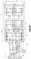
- Fig. 3A is block diagram of a circuit of a power conversion stage according to one embodiment of the present disclosure.
- a power conversion stage 12 may include:
- control module 13 is coupled to the switches of each bridge arm of the AC/DC converter 121 to control switching states of the switches of each bridge arm of the AC/DC converter 121 and the DC/DC converters 122 when the AC power terminal 11 is used for single-phase charging, single-phase discharging, three-phase charging, or three-phase discharge, so that the power conversion stage 12 realizes the corresponding operation mode.
- a portion of the control module 13 that controls the switches of each bridge arm of the AC/DC converter 121 and the DC/DC converter 122 as well as the power conversion stage 12 may be disposed in the same hardware package, and this portion is connected to other parts of the control module 13 via a signal line.
- the specific hardware setting of the control module 13 is not specifically limited in the present disclosure.
- the apparatus 1 for charging and discharging may further include: a fifth switch set S5, coupled to the control module 13, and including a first end, a second end and a third end, wherein the first end thereof is coupled to the first center line node NC1, and the second end thereof is coupled to the sixth node N6, the third end thereof is coupled to the second center line node NC2, and the first end of the fifth switch set S5 is selectively coupled to the second end (N6) or the third end (NC2) in response to a second control signal formed by the control module 13 according to the operation mode of the apparatus for charging and discharging.
- a fifth switch set S5 coupled to the control module 13, and including a first end, a second end and a third end, wherein the first end thereof is coupled to the first center line node NC1, and the second end thereof is coupled to the sixth node N6, the third end thereof is coupled to the second center line node NC2, and the first end of the fifth switch set S5 is selectively coupled to the second end (N6) or the third end (NC2)
- At least one of the first DC/DC converter 122 and the second DC/DC converter 123 is a bidirectional DC/DC converter.
- the two DC/DC converters may be connected by connecting inputs in series and connecting outputs in parallel.
- Fig. 3B illustrates another connection manner of the fifth switch group shown in Fig. 3A .
- the second end of the fifth switch group S5 may also be coupled to the sixth node N6 via a third inductance Lc.
- the first arm 1211 and the third arm 1213 can operate in a full-bridge mode, thus achieving a frequency doubling effect at the single-phase AC side.
- connection manner of the fifth switch group S5 shown in Figs. 3A and 3B may be applied not only to the circuit shown in Fig. 3A , but also to the circuit shown in Fig. 1B or other embodiments of the present disclosure.
- Fig. 4 is a flow chart of a method for charging and discharging according to an embodiment of the present disclosure.
- the method for charging and discharging 400 shown in Fig. 4 may be applied to the apparatus for charging and discharging shown in Figs. 3A and 3B .
- the method for charging may include the following steps.
- step S41 it is determined whether an operation mode of the apparatus for charging and discharging is a three-phase mode or a single-phase mode.
- step S42 in the three-phase mode, the fourth switch set S4 is controlled to be turned off, and the first end of the fifth switch set S5 is controlled to be coupled to the third end (the second center line node NC2).
- step S43 in the single-phase mode, the fourth switch set S4 is controlled to be turned on, the first end and the second end (the sixth node N6) of the fifth switch set S5 are controlled to be coupled.
- the primary side switches of the second DC/DC converter 123 is controlled to be turned on after a preset time.
- the three bridge arms 1211, 1212, and 1213 work together to charge the bus capacitors C1 and C2, and may operate in an environment with a bus voltage up to 800V.
- the first end of the fifth switch set S5 is coupled to the third end of the fifth switch set S5, the second center line node NC2 is coupled to the first center line node NC1, and the apparatus for charging and discharging operates in an environment with a bus voltage of 800V.
- the fourth switch set S4 is turned off, the two DC/DC converters work at the same time, and respectively receive 400V voltage from the 800V bus voltage for operation.
- the second end of the first switch set S1 is connected to the second node N2, and the second switch set S2 is turned on.
- the first end of the fifth switch set S5 is coupled to second end of the fifth switch set S5, and the first end of the first switch set S1 is coupled to the second end of the first switch set S1, so that the current of the first node N1 enters the first DC/DC converter 122 through the fourth node N4 and the fifth node N5, and returns to the first center line node NC1 through the sixth node N6.
- the AC/DC converter 121 may be equivalent to a full bridge circuit, at this time, the turn-on and turn-off of the fourth switch set S4 may be controlled, so as to control the connection and disconnection of the second DC/DC converter 123.
- the fourth switch set S4 may be turned on first, the residual voltage in the second bus capacitor C2 is discharged through the first resistor R1, and then the primary switches Q7b, Q8b, Q9b, QlOb in the second DC/DC converter 123 are controlled to be turned on, and the second bus capacitor C2 and the first resistor R1 are short-circuited, so that the detachment of the second DC/DC converter 123 may be realized.
- the circuits and components of the first DC/DC converter 122 and the second DC/DC converter 123 may be designed and selected according to an operating voltage of the bus voltage of 400 V, thereby greatly saving the manufacturing costs.
- the switch bridge arm 124 may also be connected in parallel with the first bus capacitor C1 and the first DC/DC converter 122, so as to control the connection and disconnection of the first DC/DC converter 122.
- Fig. 5A and Fig. 5B are block diagrams of a circuit of the apparatus for charging and discharging according to an embodiment of the present disclosure.
- the apparatus for charging and discharging further includes:
- the second end of the first switch set S1 is directly coupled to the first node N1 in the embodiment shown in Fig. 5A and Fig. 5B , in other embodiments, when the apparatus for charging and discharging includes a sixth switch set S6, the second end of the first switch set S1 may also be coupled to the second end of the sixth switch set S6.
- Fig. 6 is a flow chart of a method for charging and discharging according to an embodiment of the present disclosure.
- the method for charging and discharging shown in Fig. 6 may be applied to the apparatus for charging and discharging shown in the Fig. 5A and Fig. 5B .
- the method for charging and discharging 200 or 400 may further include:
- the third switch set S3 may be firstly turned on to make the bus capacitors C1 and/or C2 to be pre-charged through the second resistor R2.
- the sixth switch set S6 is turned on, and the current passes through the first node N1 and the fourth node N4 to charge the bus voltage to the second preset voltage V2.
- all the switch sets may be turned off, and the charging mode is determined to be the three-phase charging mode or the single-phase charging mode, and then the couple control of each switch set is controlled.
- the circuit reliability can be effectively improved by setting the pre-charge circuit.
Landscapes
- Engineering & Computer Science (AREA)
- Power Engineering (AREA)
- Business, Economics & Management (AREA)
- Emergency Management (AREA)
- Transportation (AREA)
- Mechanical Engineering (AREA)
- Charge And Discharge Circuits For Batteries Or The Like (AREA)
Applications Claiming Priority (2)
| Application Number | Priority Date | Filing Date | Title |
|---|---|---|---|
| CN201811045180.XA CN109861357A (zh) | 2018-09-07 | 2018-09-07 | 充放电方法与装置 |
| CN201910713081.2A CN110233514B (zh) | 2018-09-07 | 2019-08-02 | 充放电装置与充放电方法 |
Publications (2)
| Publication Number | Publication Date |
|---|---|
| EP3621174A1 true EP3621174A1 (de) | 2020-03-11 |
| EP3621174B1 EP3621174B1 (de) | 2023-05-10 |
Family
ID=66889729
Family Applications (1)
| Application Number | Title | Priority Date | Filing Date |
|---|---|---|---|
| EP19196020.2A Active EP3621174B1 (de) | 2018-09-07 | 2019-09-06 | Verfahren und vorrichtung zum laden und entladen |
Country Status (3)
| Country | Link |
|---|---|
| US (1) | US11251625B2 (de) |
| EP (1) | EP3621174B1 (de) |
| CN (2) | CN109861357A (de) |
Cited By (7)
| Publication number | Priority date | Publication date | Assignee | Title |
|---|---|---|---|---|
| WO2021063593A1 (de) * | 2019-10-02 | 2021-04-08 | HELLA GmbH & Co. KGaA | Bidirektionaler stromrichter mit zwischenkreis |
| WO2021122452A1 (fr) * | 2019-12-20 | 2021-06-24 | Valeo Siemens Eautomotive France Sas | Système de filtre hybride monophasé et triphasé, pour un chargeur électrique |
| WO2021205040A1 (en) * | 2020-04-10 | 2021-10-14 | Prodrive Technologies Innovation Services B.V. | Electrical power converter |
| EP3922504A4 (de) * | 2019-06-25 | 2022-04-13 | Huawei Digital Power Technologies Co., Ltd. | Fahrzeugmontierte lade-/entladevorrichtung und system |
| EP4047782A1 (de) * | 2021-02-22 | 2022-08-24 | Watt & Well | Universelles und vielseitiges ladegerät für eine elektrofahrzeugbatterie |
| EP4216416A1 (de) * | 2022-01-19 | 2023-07-26 | Borgwarner Luxembourg Automotive Systems SA | Systeme und verfahren für bidirektionales batterieladegerät mit universeller eingangsleistungsversorgung |
| WO2024183871A1 (en) * | 2023-03-03 | 2024-09-12 | Abb Schweiz Ag | Method of controlling power supply to electric actuator, power system and robot system |
Families Citing this family (47)
| Publication number | Priority date | Publication date | Assignee | Title |
|---|---|---|---|---|
| EP3648322A1 (de) * | 2018-10-30 | 2020-05-06 | Mahle International GmbH | Bordladegeräte (obc) |
| CN111446860B (zh) * | 2019-01-16 | 2021-09-21 | 台达电子企业管理(上海)有限公司 | 直流/直流变换器及其控制方法 |
| CN111446861B (zh) * | 2019-01-16 | 2021-02-26 | 台达电子企业管理(上海)有限公司 | 直流/直流变换器及其控制方法 |
| CN110460260B (zh) * | 2019-08-07 | 2020-12-15 | 华为技术有限公司 | 一种变换器及供电系统 |
| CN112448425B (zh) * | 2019-08-30 | 2023-03-14 | 比亚迪股份有限公司 | 故障处理方法、系统及其存储介质 |
| CN112448458B (zh) * | 2019-08-30 | 2023-05-05 | 比亚迪股份有限公司 | 故障处理方法、系统及其存储介质 |
| US10855169B1 (en) * | 2019-09-10 | 2020-12-01 | Lear Corporation | Configurable multi-phase charger |
| CN110556901A (zh) * | 2019-09-23 | 2019-12-10 | 台达电子企业管理(上海)有限公司 | 车载充放电系统 |
| CN111313519A (zh) * | 2019-12-31 | 2020-06-19 | 中国重汽集团济南动力有限公司 | 一种大功率车载充电集成系统及方法 |
| CN111146851A (zh) * | 2020-03-12 | 2020-05-12 | 深圳威迈斯新能源股份有限公司 | 一种单三相兼容的转换电路及车载充电机 |
| CN111355287B (zh) * | 2020-03-23 | 2022-04-08 | 台达电子企业管理(上海)有限公司 | 车载充电机 |
| WO2021196309A1 (zh) * | 2020-03-31 | 2021-10-07 | 华为技术有限公司 | 双向能量传输装置、车载充电器及电动汽车 |
| CN113872308A (zh) * | 2020-06-29 | 2021-12-31 | 比亚迪股份有限公司 | 充电系统和汽车 |
| WO2022011532A1 (zh) * | 2020-07-14 | 2022-01-20 | 深圳欣锐科技股份有限公司 | 三相充电和单相充电相互切换电路和相关装置 |
| CN111775709A (zh) * | 2020-07-15 | 2020-10-16 | 东风柳州汽车有限公司 | 车载充电电路、控制方法、系统及纯电动汽车 |
| CN114074561B (zh) * | 2020-08-20 | 2023-07-11 | 比亚迪股份有限公司 | 能量转换装置及其运行方法、电动汽车 |
| JP7302558B2 (ja) | 2020-09-07 | 2023-07-04 | トヨタ自動車株式会社 | 充電装置および充電装置の制御方法 |
| CN213661257U (zh) * | 2020-10-13 | 2021-07-09 | 比亚迪股份有限公司 | 充电装置和车辆 |
| CN112383213A (zh) * | 2020-11-17 | 2021-02-19 | 珠海格力电器股份有限公司 | 直流母线充放电一体电路和方法、电器设备 |
| KR102646734B1 (ko) * | 2020-11-26 | 2024-03-13 | 엘지이노텍 주식회사 | 직류/직류 컨버터 및 이의 제어 방법 |
| DE102020215784A1 (de) * | 2020-12-14 | 2022-06-15 | Vitesco Technologies GmbH | Fahrzeugladeschaltung mit Gleichrichtereinrichtung, Zwischenkreiskondensator und Vor-/Entladeschaltung |
| CN112744101B (zh) * | 2020-12-25 | 2023-02-17 | 中国第一汽车股份有限公司 | 充放电控制系统、方法及交通工具 |
| CN112810469B (zh) * | 2021-01-08 | 2023-02-24 | 东风柳州汽车有限公司 | 充放电转换电路、控制方法及充放电合用枪头 |
| CN112865554B (zh) * | 2021-01-19 | 2024-08-27 | 江苏金智科技股份有限公司 | 一种单相或三相交流电源复用型的电力电子负载装置 |
| US12230992B2 (en) | 2021-01-29 | 2025-02-18 | Lear Corporation | On-board charger (OBC) method and system for detecting phase configuration of mains supply and for diagnosing status of OBC phase configuration relays |
| KR20220142796A (ko) * | 2021-04-15 | 2022-10-24 | 현대자동차주식회사 | 충전 장치 |
| CN113394996A (zh) * | 2021-06-07 | 2021-09-14 | 深圳威迈斯新能源股份有限公司 | Ac-dc谐振变换电路及其控制方法 |
| TWI776564B (zh) * | 2021-06-25 | 2022-09-01 | 台達電子工業股份有限公司 | 單相與三相兼容的交流直流轉換電路及其放電控制方法 |
| CN115528929A (zh) | 2021-06-25 | 2022-12-27 | 台达电子工业股份有限公司 | 单相与三相兼容的交流直流转换电路及其放电控制方法 |
| US11955908B2 (en) * | 2021-07-28 | 2024-04-09 | Apple Inc. | Auto-configurable energy storage system |
| CN115700981A (zh) | 2021-07-30 | 2023-02-07 | 台达电子工业股份有限公司 | 交流直流转换电路及其输入电流检测方法 |
| EP4131759A1 (de) * | 2021-08-03 | 2023-02-08 | Watt & Well | Hochintegriertes mosfet-halbbrückenleistungsmodul für stromrichter |
| CN114362498A (zh) * | 2021-11-24 | 2022-04-15 | 漳州科华技术有限责任公司 | 三相pfc电路的控制方法、装置、控制设备及存储介质 |
| EP4195474A1 (de) | 2021-12-09 | 2023-06-14 | Viessmann Climate Solutions SE | Leistungsumwandlungsvorrichtung und verfahren zum verbinden einer leistungsumwandlungsvorrichtung mit einer wechselstromversorgung |
| DE102021214405B4 (de) * | 2021-12-15 | 2023-11-16 | Zf Friedrichshafen Ag | Wechselrichtervorrichtung für ein Fahrzeug und Verfahren zum Betreiben einer Wechselrichtervorrichtung |
| CN114583815B (zh) * | 2022-01-28 | 2026-02-13 | 哈尔滨理工大学 | 电动汽车车载充电与驱动电机的集成系统及其工作方法 |
| US20250141368A1 (en) * | 2022-02-17 | 2025-05-01 | Dynapower Company Llc | Apparatuses and methods for power supply realization using multiple inverters |
| DE102022206477A1 (de) * | 2022-06-28 | 2023-12-28 | Robert Bosch Gesellschaft mit beschränkter Haftung | Ladegerät und Verfahren zum Betrieb des Ladegerätes |
| CN115230506B (zh) * | 2022-07-05 | 2025-04-01 | 华为数字能源技术有限公司 | 双向车载充电机、车载动力系统及电动车辆 |
| CN117656894B (zh) * | 2022-08-30 | 2024-10-11 | 比亚迪股份有限公司 | 充电机、充电机控制方法及车辆 |
| JP7733631B2 (ja) * | 2022-10-31 | 2025-09-03 | 株式会社Soken | 電力変換装置、プログラム |
| CN116080435B (zh) * | 2022-11-29 | 2026-03-06 | 深圳威迈斯新能源(集团)股份有限公司 | 带充放电功能的双向车载obc控制电路及其控制方法 |
| US12542447B2 (en) * | 2022-12-30 | 2026-02-03 | Rivian Ip Holdings, Llc | Simultaneous charging and power export using n-leg converter |
| CN116247949A (zh) * | 2022-12-30 | 2023-06-09 | 苏州博思得电气有限公司 | 一种高压发生器 |
| JP2024141633A (ja) * | 2023-03-29 | 2024-10-10 | 株式会社豊田自動織機 | 電力変換装置 |
| US20250132686A1 (en) * | 2023-10-20 | 2025-04-24 | Infineon Technologies Austria Ag | Multi-Phase Resonant Power Converter |
| DE102024208111A1 (de) * | 2024-08-27 | 2026-03-05 | Robert Bosch Gesellschaft mit beschränkter Haftung | Ladeeinrichtung und Verfahren zum Betreiben einer solchen |
Citations (7)
| Publication number | Priority date | Publication date | Assignee | Title |
|---|---|---|---|---|
| CN102201693A (zh) * | 2011-06-07 | 2011-09-28 | 天宝电子(惠州)有限公司 | 一种电动汽车车载充电系统 |
| EP2800226A1 (de) * | 2011-12-31 | 2014-11-05 | Shenzhen BYD Auto R&D Company Limited | Elektrofahrzeug und stromversorgungssystem sowie motorsteuerung für ein elektrofahrzeug |
| CN204089305U (zh) * | 2014-08-26 | 2015-01-07 | 国家电网公司 | 一种应用于无人机自动充电的电源系统 |
| US20160121740A1 (en) * | 2013-05-10 | 2016-05-05 | Audi Ag | Method for operating a charging device for single-phase and multi-phase charging of an energy store in a motor vehicle and charging device |
| CN105896693A (zh) * | 2016-05-17 | 2016-08-24 | 中能易电新能源技术有限公司 | 智能交流充电桩的充电电路及充电方法和装置 |
| US20170179745A1 (en) * | 2014-09-04 | 2017-06-22 | Fraunhofer-Gesellschaft Zur Foerderung Der Angewandten Forschung E.V. | Device for charging an energy store |
| FR3060230A1 (fr) * | 2016-12-14 | 2018-06-15 | Renault S.A.S | Procede de commande d'un dispositif de charge embarque sur un vehicule electrique ou hybride. |
Family Cites Families (16)
| Publication number | Priority date | Publication date | Assignee | Title |
|---|---|---|---|---|
| KR101479241B1 (ko) * | 2008-08-08 | 2015-01-05 | 삼성전자 주식회사 | 3상 전원의 단상 제어 회로 |
| US9077202B1 (en) * | 2009-12-31 | 2015-07-07 | Sunpower Corporation | Power converter with series energy storage |
| CN103187772B (zh) | 2011-12-31 | 2016-08-17 | 比亚迪股份有限公司 | 电动汽车及电动汽车向外供电的系统 |
| CN103401433A (zh) | 2013-06-24 | 2013-11-20 | 北京千驷驭电气有限公司 | 适用多供电模式的混合动力动车组牵引变流器 |
| JP2015208065A (ja) * | 2014-04-17 | 2015-11-19 | 株式会社豊田自動織機 | 車両充電システム |
| CN105703420B (zh) | 2014-11-28 | 2018-06-29 | 上海汽车集团股份有限公司 | 控制系统及其控制方法和汽车 |
| CN104682430B (zh) * | 2015-02-16 | 2016-08-17 | 东北大学 | 一种应用于能源互联网的能源路由器装置 |
| US10389271B2 (en) * | 2015-11-06 | 2019-08-20 | Hongliang Wang | Single-phase four-level inverter circuit topology and three-phase four-level inverter circuit topology |
| CN105425066A (zh) * | 2015-11-16 | 2016-03-23 | 来恩伟业(鹤壁)电子科技有限责任公司 | 一种柔性直流输电专用电容器纹波电流检测主电路 |
| CN206490487U (zh) | 2017-02-09 | 2017-09-12 | 上海欣锐电控技术有限公司 | 一种车载充电机以及车载充电系统 |
| DE102017108099B4 (de) * | 2017-04-13 | 2019-03-28 | Universität der Bundeswehr München | Stromrichter für Energieübertragung |
| CN107104443B (zh) * | 2017-06-21 | 2023-05-23 | 西南交通大学 | 一种电力电子变压器 |
| CN109494706A (zh) * | 2017-09-11 | 2019-03-19 | 台达电子工业股份有限公司 | 整合式供电系统 |
| CN107947309B (zh) | 2017-12-06 | 2019-07-16 | 深圳威迈斯新能源股份有限公司 | 兼容单相三相交流电的充电控制电路 |
| WO2019244680A1 (ja) * | 2018-06-18 | 2019-12-26 | 田中 正一 | 電気自動車のパワーシステム |
| US11757292B2 (en) * | 2020-05-11 | 2023-09-12 | Baidu Usa Llc | Circuit design for power converter with bidirectional charging and discharging and including a self-inspection mode |
-
2018
- 2018-09-07 CN CN201811045180.XA patent/CN109861357A/zh active Pending
-
2019
- 2019-08-02 CN CN201910713081.2A patent/CN110233514B/zh active Active
- 2019-09-04 US US16/559,733 patent/US11251625B2/en active Active
- 2019-09-06 EP EP19196020.2A patent/EP3621174B1/de active Active
Patent Citations (7)
| Publication number | Priority date | Publication date | Assignee | Title |
|---|---|---|---|---|
| CN102201693A (zh) * | 2011-06-07 | 2011-09-28 | 天宝电子(惠州)有限公司 | 一种电动汽车车载充电系统 |
| EP2800226A1 (de) * | 2011-12-31 | 2014-11-05 | Shenzhen BYD Auto R&D Company Limited | Elektrofahrzeug und stromversorgungssystem sowie motorsteuerung für ein elektrofahrzeug |
| US20160121740A1 (en) * | 2013-05-10 | 2016-05-05 | Audi Ag | Method for operating a charging device for single-phase and multi-phase charging of an energy store in a motor vehicle and charging device |
| CN204089305U (zh) * | 2014-08-26 | 2015-01-07 | 国家电网公司 | 一种应用于无人机自动充电的电源系统 |
| US20170179745A1 (en) * | 2014-09-04 | 2017-06-22 | Fraunhofer-Gesellschaft Zur Foerderung Der Angewandten Forschung E.V. | Device for charging an energy store |
| CN105896693A (zh) * | 2016-05-17 | 2016-08-24 | 中能易电新能源技术有限公司 | 智能交流充电桩的充电电路及充电方法和装置 |
| FR3060230A1 (fr) * | 2016-12-14 | 2018-06-15 | Renault S.A.S | Procede de commande d'un dispositif de charge embarque sur un vehicule electrique ou hybride. |
Non-Patent Citations (1)
| Title |
|---|
| ARNALDO ARANCIBIA ET AL: "A Unified Single- and Three-Phase Control for Grid Connected Electric Vehicles", IEEE TRANSACTIONS ON SMART GRID, vol. 4, no. 4, 1 December 2013 (2013-12-01), USA, pages 1780 - 1790, XP055403240, ISSN: 1949-3053, DOI: 10.1109/TSG.2013.2271096 * |
Cited By (13)
| Publication number | Priority date | Publication date | Assignee | Title |
|---|---|---|---|---|
| EP3922504A4 (de) * | 2019-06-25 | 2022-04-13 | Huawei Digital Power Technologies Co., Ltd. | Fahrzeugmontierte lade-/entladevorrichtung und system |
| US12445040B2 (en) | 2019-10-02 | 2025-10-14 | HELLA GmbH & Co. KGaA | Bidirectional power converter having intermediate circuit |
| WO2021063593A1 (de) * | 2019-10-02 | 2021-04-08 | HELLA GmbH & Co. KGaA | Bidirektionaler stromrichter mit zwischenkreis |
| WO2021122452A1 (fr) * | 2019-12-20 | 2021-06-24 | Valeo Siemens Eautomotive France Sas | Système de filtre hybride monophasé et triphasé, pour un chargeur électrique |
| FR3105652A1 (fr) * | 2019-12-20 | 2021-06-25 | Valeo Siemens Eautomotive France Sas | Système de filtre hybride monophasé et triphasé, pour un chargeur électrique |
| US12611946B2 (en) | 2019-12-20 | 2026-04-28 | Valeo Siemens Eautomotive France Sas | Single-phase and three-phase hybrid filter system for an electric charger |
| WO2021205040A1 (en) * | 2020-04-10 | 2021-10-14 | Prodrive Technologies Innovation Services B.V. | Electrical power converter |
| NL2025328B1 (en) * | 2020-04-10 | 2021-10-26 | Prodrive Tech Bv | Electrical power converter |
| EP4047782A1 (de) * | 2021-02-22 | 2022-08-24 | Watt & Well | Universelles und vielseitiges ladegerät für eine elektrofahrzeugbatterie |
| US12206273B2 (en) | 2021-02-22 | 2025-01-21 | Watt & Well | Universal and versatile charger for electric vehicle battery |
| US12280684B2 (en) | 2022-01-19 | 2025-04-22 | Borgwarner Luxembourg Automotive Systems Sa | Systems and methods for universal input power supply bi-directional battery charger |
| EP4216416A1 (de) * | 2022-01-19 | 2023-07-26 | Borgwarner Luxembourg Automotive Systems SA | Systeme und verfahren für bidirektionales batterieladegerät mit universeller eingangsleistungsversorgung |
| WO2024183871A1 (en) * | 2023-03-03 | 2024-09-12 | Abb Schweiz Ag | Method of controlling power supply to electric actuator, power system and robot system |
Also Published As
| Publication number | Publication date |
|---|---|
| CN109861357A (zh) | 2019-06-07 |
| US11251625B2 (en) | 2022-02-15 |
| US20200083727A1 (en) | 2020-03-12 |
| EP3621174B1 (de) | 2023-05-10 |
| CN110233514A (zh) | 2019-09-13 |
| CN110233514B (zh) | 2021-04-16 |
Similar Documents
| Publication | Publication Date | Title |
|---|---|---|
| EP3621174B1 (de) | Verfahren und vorrichtung zum laden und entladen | |
| CN109889077B (zh) | 单相和三相兼容的ac/dc电路及充放电装置 | |
| US9166501B2 (en) | Power supply unit for converting power between DC and AC and operating method of the same | |
| CN110677060A (zh) | 功率变换系统及其中直流母线电容的预充电方法 | |
| EP3255771B1 (de) | Bidirektionaler gleichspannungswandler | |
| CN113595374B (zh) | 一种功率变换器的主动放电方法和控制器 | |
| CN113972702B (zh) | 供电装置以及供电控制方法 | |
| EP3506457A1 (de) | Stromladesystem mit niedrigem standby-stromverbrauch und verfahren zu dessen steuerung | |
| CN111725981A (zh) | 一种光伏逆变器、光伏系统及放电控制方法 | |
| AU2022419837B2 (en) | Vehicle, and energy conversion device and discharging method therefor | |
| CN117411155A (zh) | 一种充电装置、充电桩及充电系统 | |
| CN110829575A (zh) | 缓启母线电路、方法和不间断电源 | |
| EP4142102A2 (de) | Stromversorgungssystem | |
| CN112994410A (zh) | 电力电子变压器系统直流母线电容的均压控制装置和方法 | |
| JP4144009B2 (ja) | 可変電圧型蓄電装置およびハイブリッド型電源装置 | |
| KR20210141353A (ko) | 단상 및 3상 겸용 충전시스템 | |
| CN103187746B (zh) | 一种不间断电源拓扑 | |
| US11569754B2 (en) | Single-phase and three-phase compatible AC-DC conversion circuit and method of controlling charge and discharge thereof | |
| CN108879651A (zh) | 基于dab的大功率双重模块化混合储能系统及并网方法 | |
| CN112952926B (zh) | 一种多电池切换控制电路、装置、系统及控制方法 | |
| CN101237072B (zh) | 一种模块化ups中实现电池充电的方法 | |
| CN115719952B (zh) | 双极直流配电网中单极源荷的极性切换稳定控制方法 | |
| CN204168175U (zh) | 一种可实现直流灵活配置的光伏逆变器 | |
| CN223625625U (zh) | 电池备份电源电路及系统 | |
| CN219611615U (zh) | 双向电压变换电路及电子设备 |
Legal Events
| Date | Code | Title | Description |
|---|---|---|---|
| PUAI | Public reference made under article 153(3) epc to a published international application that has entered the european phase |
Free format text: ORIGINAL CODE: 0009012 |
|
| STAA | Information on the status of an ep patent application or granted ep patent |
Free format text: STATUS: REQUEST FOR EXAMINATION WAS MADE |
|
| 17P | Request for examination filed |
Effective date: 20190906 |
|
| AK | Designated contracting states |
Kind code of ref document: A1 Designated state(s): AL AT BE BG CH CY CZ DE DK EE ES FI FR GB GR HR HU IE IS IT LI LT LU LV MC MK MT NL NO PL PT RO RS SE SI SK SM TR |
|
| AX | Request for extension of the european patent |
Extension state: BA ME |
|
| STAA | Information on the status of an ep patent application or granted ep patent |
Free format text: STATUS: EXAMINATION IS IN PROGRESS |
|
| 17Q | First examination report despatched |
Effective date: 20211215 |
|
| REG | Reference to a national code |
Ref country code: DE Ref legal event code: R079 Ref document number: 602019028633 Country of ref document: DE Free format text: PREVIOUS MAIN CLASS: H02J0007020000 Ipc: B60L0053200000 |
|
| RIC1 | Information provided on ipc code assigned before grant |
Ipc: H02M 7/12 20060101ALN20221129BHEP Ipc: H02M 3/28 20060101ALN20221129BHEP Ipc: H02M 1/36 20070101ALN20221129BHEP Ipc: H02M 1/00 20060101ALN20221129BHEP Ipc: H02J 7/02 20160101ALN20221129BHEP Ipc: H02M 7/797 20060101ALI20221129BHEP Ipc: H02M 3/335 20060101ALI20221129BHEP Ipc: H02M 1/10 20060101ALI20221129BHEP Ipc: B60L 53/20 20190101AFI20221129BHEP |
|
| GRAP | Despatch of communication of intention to grant a patent |
Free format text: ORIGINAL CODE: EPIDOSNIGR1 |
|
| STAA | Information on the status of an ep patent application or granted ep patent |
Free format text: STATUS: GRANT OF PATENT IS INTENDED |
|
| INTG | Intention to grant announced |
Effective date: 20230109 |
|
| GRAS | Grant fee paid |
Free format text: ORIGINAL CODE: EPIDOSNIGR3 |
|
| GRAA | (expected) grant |
Free format text: ORIGINAL CODE: 0009210 |
|
| STAA | Information on the status of an ep patent application or granted ep patent |
Free format text: STATUS: THE PATENT HAS BEEN GRANTED |
|
| AK | Designated contracting states |
Kind code of ref document: B1 Designated state(s): AL AT BE BG CH CY CZ DE DK EE ES FI FR GB GR HR HU IE IS IT LI LT LU LV MC MK MT NL NO PL PT RO RS SE SI SK SM TR |
|
| REG | Reference to a national code |
Ref country code: GB Ref legal event code: FG4D |
|
| REG | Reference to a national code |
Ref country code: AT Ref legal event code: REF Ref document number: 1566380 Country of ref document: AT Kind code of ref document: T Effective date: 20230515 Ref country code: CH Ref legal event code: EP |
|
| REG | Reference to a national code |
Ref country code: DE Ref legal event code: R096 Ref document number: 602019028633 Country of ref document: DE |
|
| REG | Reference to a national code |
Ref country code: IE Ref legal event code: FG4D |
|
| P01 | Opt-out of the competence of the unified patent court (upc) registered |
Effective date: 20230524 |
|
| REG | Reference to a national code |
Ref country code: SE Ref legal event code: TRGR |
|
| REG | Reference to a national code |
Ref country code: LT Ref legal event code: MG9D |
|
| REG | Reference to a national code |
Ref country code: NL Ref legal event code: MP Effective date: 20230510 |
|
| REG | Reference to a national code |
Ref country code: AT Ref legal event code: MK05 Ref document number: 1566380 Country of ref document: AT Kind code of ref document: T Effective date: 20230510 |
|
| PG25 | Lapsed in a contracting state [announced via postgrant information from national office to epo] |
Ref country code: PT Free format text: LAPSE BECAUSE OF FAILURE TO SUBMIT A TRANSLATION OF THE DESCRIPTION OR TO PAY THE FEE WITHIN THE PRESCRIBED TIME-LIMIT Effective date: 20230911 Ref country code: NO Free format text: LAPSE BECAUSE OF FAILURE TO SUBMIT A TRANSLATION OF THE DESCRIPTION OR TO PAY THE FEE WITHIN THE PRESCRIBED TIME-LIMIT Effective date: 20230810 Ref country code: NL Free format text: LAPSE BECAUSE OF FAILURE TO SUBMIT A TRANSLATION OF THE DESCRIPTION OR TO PAY THE FEE WITHIN THE PRESCRIBED TIME-LIMIT Effective date: 20230510 Ref country code: ES Free format text: LAPSE BECAUSE OF FAILURE TO SUBMIT A TRANSLATION OF THE DESCRIPTION OR TO PAY THE FEE WITHIN THE PRESCRIBED TIME-LIMIT Effective date: 20230510 Ref country code: AT Free format text: LAPSE BECAUSE OF FAILURE TO SUBMIT A TRANSLATION OF THE DESCRIPTION OR TO PAY THE FEE WITHIN THE PRESCRIBED TIME-LIMIT Effective date: 20230510 |
|
| PG25 | Lapsed in a contracting state [announced via postgrant information from national office to epo] |
Ref country code: RS Free format text: LAPSE BECAUSE OF FAILURE TO SUBMIT A TRANSLATION OF THE DESCRIPTION OR TO PAY THE FEE WITHIN THE PRESCRIBED TIME-LIMIT Effective date: 20230510 Ref country code: PL Free format text: LAPSE BECAUSE OF FAILURE TO SUBMIT A TRANSLATION OF THE DESCRIPTION OR TO PAY THE FEE WITHIN THE PRESCRIBED TIME-LIMIT Effective date: 20230510 Ref country code: LV Free format text: LAPSE BECAUSE OF FAILURE TO SUBMIT A TRANSLATION OF THE DESCRIPTION OR TO PAY THE FEE WITHIN THE PRESCRIBED TIME-LIMIT Effective date: 20230510 Ref country code: LT Free format text: LAPSE BECAUSE OF FAILURE TO SUBMIT A TRANSLATION OF THE DESCRIPTION OR TO PAY THE FEE WITHIN THE PRESCRIBED TIME-LIMIT Effective date: 20230510 Ref country code: IS Free format text: LAPSE BECAUSE OF FAILURE TO SUBMIT A TRANSLATION OF THE DESCRIPTION OR TO PAY THE FEE WITHIN THE PRESCRIBED TIME-LIMIT Effective date: 20230910 Ref country code: HR Free format text: LAPSE BECAUSE OF FAILURE TO SUBMIT A TRANSLATION OF THE DESCRIPTION OR TO PAY THE FEE WITHIN THE PRESCRIBED TIME-LIMIT Effective date: 20230510 Ref country code: GR Free format text: LAPSE BECAUSE OF FAILURE TO SUBMIT A TRANSLATION OF THE DESCRIPTION OR TO PAY THE FEE WITHIN THE PRESCRIBED TIME-LIMIT Effective date: 20230811 |
|
| PG25 | Lapsed in a contracting state [announced via postgrant information from national office to epo] |
Ref country code: FI Free format text: LAPSE BECAUSE OF FAILURE TO SUBMIT A TRANSLATION OF THE DESCRIPTION OR TO PAY THE FEE WITHIN THE PRESCRIBED TIME-LIMIT Effective date: 20230510 |
|
| PG25 | Lapsed in a contracting state [announced via postgrant information from national office to epo] |
Ref country code: SK Free format text: LAPSE BECAUSE OF FAILURE TO SUBMIT A TRANSLATION OF THE DESCRIPTION OR TO PAY THE FEE WITHIN THE PRESCRIBED TIME-LIMIT Effective date: 20230510 |
|
| PG25 | Lapsed in a contracting state [announced via postgrant information from national office to epo] |
Ref country code: SM Free format text: LAPSE BECAUSE OF FAILURE TO SUBMIT A TRANSLATION OF THE DESCRIPTION OR TO PAY THE FEE WITHIN THE PRESCRIBED TIME-LIMIT Effective date: 20230510 Ref country code: SK Free format text: LAPSE BECAUSE OF FAILURE TO SUBMIT A TRANSLATION OF THE DESCRIPTION OR TO PAY THE FEE WITHIN THE PRESCRIBED TIME-LIMIT Effective date: 20230510 Ref country code: RO Free format text: LAPSE BECAUSE OF FAILURE TO SUBMIT A TRANSLATION OF THE DESCRIPTION OR TO PAY THE FEE WITHIN THE PRESCRIBED TIME-LIMIT Effective date: 20230510 Ref country code: EE Free format text: LAPSE BECAUSE OF FAILURE TO SUBMIT A TRANSLATION OF THE DESCRIPTION OR TO PAY THE FEE WITHIN THE PRESCRIBED TIME-LIMIT Effective date: 20230510 Ref country code: DK Free format text: LAPSE BECAUSE OF FAILURE TO SUBMIT A TRANSLATION OF THE DESCRIPTION OR TO PAY THE FEE WITHIN THE PRESCRIBED TIME-LIMIT Effective date: 20230510 Ref country code: CZ Free format text: LAPSE BECAUSE OF FAILURE TO SUBMIT A TRANSLATION OF THE DESCRIPTION OR TO PAY THE FEE WITHIN THE PRESCRIBED TIME-LIMIT Effective date: 20230510 |
|
| REG | Reference to a national code |
Ref country code: DE Ref legal event code: R097 Ref document number: 602019028633 Country of ref document: DE |
|
| PLBE | No opposition filed within time limit |
Free format text: ORIGINAL CODE: 0009261 |
|
| STAA | Information on the status of an ep patent application or granted ep patent |
Free format text: STATUS: NO OPPOSITION FILED WITHIN TIME LIMIT |
|
| 26N | No opposition filed |
Effective date: 20240213 |
|
| REG | Reference to a national code |
Ref country code: CH Ref legal event code: PL |
|
| PG25 | Lapsed in a contracting state [announced via postgrant information from national office to epo] |
Ref country code: SI Free format text: LAPSE BECAUSE OF FAILURE TO SUBMIT A TRANSLATION OF THE DESCRIPTION OR TO PAY THE FEE WITHIN THE PRESCRIBED TIME-LIMIT Effective date: 20230510 |
|
| PG25 | Lapsed in a contracting state [announced via postgrant information from national office to epo] |
Ref country code: LU Free format text: LAPSE BECAUSE OF NON-PAYMENT OF DUE FEES Effective date: 20230906 |
|
| REG | Reference to a national code |
Ref country code: BE Ref legal event code: MM Effective date: 20230930 |
|
| GBPC | Gb: european patent ceased through non-payment of renewal fee |
Effective date: 20230906 |
|
| PG25 | Lapsed in a contracting state [announced via postgrant information from national office to epo] |
Ref country code: SI Free format text: LAPSE BECAUSE OF FAILURE TO SUBMIT A TRANSLATION OF THE DESCRIPTION OR TO PAY THE FEE WITHIN THE PRESCRIBED TIME-LIMIT Effective date: 20230510 Ref country code: LU Free format text: LAPSE BECAUSE OF NON-PAYMENT OF DUE FEES Effective date: 20230906 Ref country code: IT Free format text: LAPSE BECAUSE OF FAILURE TO SUBMIT A TRANSLATION OF THE DESCRIPTION OR TO PAY THE FEE WITHIN THE PRESCRIBED TIME-LIMIT Effective date: 20230510 Ref country code: MC Free format text: LAPSE BECAUSE OF FAILURE TO SUBMIT A TRANSLATION OF THE DESCRIPTION OR TO PAY THE FEE WITHIN THE PRESCRIBED TIME-LIMIT Effective date: 20230510 |
|
| REG | Reference to a national code |
Ref country code: IE Ref legal event code: MM4A |
|
| PG25 | Lapsed in a contracting state [announced via postgrant information from national office to epo] |
Ref country code: IE Free format text: LAPSE BECAUSE OF NON-PAYMENT OF DUE FEES Effective date: 20230906 |
|
| PG25 | Lapsed in a contracting state [announced via postgrant information from national office to epo] |
Ref country code: GB Free format text: LAPSE BECAUSE OF NON-PAYMENT OF DUE FEES Effective date: 20230906 |
|
| PG25 | Lapsed in a contracting state [announced via postgrant information from national office to epo] |
Ref country code: CH Free format text: LAPSE BECAUSE OF NON-PAYMENT OF DUE FEES Effective date: 20230930 |
|
| PG25 | Lapsed in a contracting state [announced via postgrant information from national office to epo] |
Ref country code: IE Free format text: LAPSE BECAUSE OF NON-PAYMENT OF DUE FEES Effective date: 20230906 Ref country code: GB Free format text: LAPSE BECAUSE OF NON-PAYMENT OF DUE FEES Effective date: 20230906 Ref country code: CH Free format text: LAPSE BECAUSE OF NON-PAYMENT OF DUE FEES Effective date: 20230930 |
|
| PG25 | Lapsed in a contracting state [announced via postgrant information from national office to epo] |
Ref country code: BE Free format text: LAPSE BECAUSE OF NON-PAYMENT OF DUE FEES Effective date: 20230930 |
|
| PG25 | Lapsed in a contracting state [announced via postgrant information from national office to epo] |
Ref country code: BG Free format text: LAPSE BECAUSE OF FAILURE TO SUBMIT A TRANSLATION OF THE DESCRIPTION OR TO PAY THE FEE WITHIN THE PRESCRIBED TIME-LIMIT Effective date: 20230510 |
|
| PG25 | Lapsed in a contracting state [announced via postgrant information from national office to epo] |
Ref country code: BG Free format text: LAPSE BECAUSE OF FAILURE TO SUBMIT A TRANSLATION OF THE DESCRIPTION OR TO PAY THE FEE WITHIN THE PRESCRIBED TIME-LIMIT Effective date: 20230510 |
|
| PG25 | Lapsed in a contracting state [announced via postgrant information from national office to epo] |
Ref country code: CY Free format text: LAPSE BECAUSE OF FAILURE TO SUBMIT A TRANSLATION OF THE DESCRIPTION OR TO PAY THE FEE WITHIN THE PRESCRIBED TIME-LIMIT; INVALID AB INITIO Effective date: 20190906 |
|
| PG25 | Lapsed in a contracting state [announced via postgrant information from national office to epo] |
Ref country code: HU Free format text: LAPSE BECAUSE OF FAILURE TO SUBMIT A TRANSLATION OF THE DESCRIPTION OR TO PAY THE FEE WITHIN THE PRESCRIBED TIME-LIMIT; INVALID AB INITIO Effective date: 20190906 |
|
| PGFP | Annual fee paid to national office [announced via postgrant information from national office to epo] |
Ref country code: DE Payment date: 20250702 Year of fee payment: 7 |
|
| PGFP | Annual fee paid to national office [announced via postgrant information from national office to epo] |
Ref country code: FR Payment date: 20250703 Year of fee payment: 7 |
|
| PGFP | Annual fee paid to national office [announced via postgrant information from national office to epo] |
Ref country code: SE Payment date: 20250702 Year of fee payment: 7 |
|
| PG25 | Lapsed in a contracting state [announced via postgrant information from national office to epo] |
Ref country code: TR Free format text: LAPSE BECAUSE OF FAILURE TO SUBMIT A TRANSLATION OF THE DESCRIPTION OR TO PAY THE FEE WITHIN THE PRESCRIBED TIME-LIMIT Effective date: 20230510 |