EP3621504B1 - Desinfektionsvorrichtung unter verwendung von vernebelung - Google Patents
Desinfektionsvorrichtung unter verwendung von vernebelung Download PDFInfo
- Publication number
- EP3621504B1 EP3621504B1 EP18728439.3A EP18728439A EP3621504B1 EP 3621504 B1 EP3621504 B1 EP 3621504B1 EP 18728439 A EP18728439 A EP 18728439A EP 3621504 B1 EP3621504 B1 EP 3621504B1
- Authority
- EP
- European Patent Office
- Prior art keywords
- disinfection
- aerosol
- injection
- air
- enclosure
- Prior art date
- Legal status (The legal status is an assumption and is not a legal conclusion. Google has not performed a legal analysis and makes no representation as to the accuracy of the status listed.)
- Active
Links
Images


Classifications
-
- A—HUMAN NECESSITIES
- A47—FURNITURE; DOMESTIC ARTICLES OR APPLIANCES; COFFEE MILLS; SPICE MILLS; SUCTION CLEANERS IN GENERAL
- A47K—SANITARY EQUIPMENT; ACCESSORIES THEREFOR, e.g. TOILET ACCESSORIES
- A47K7/00—Body washing or cleaning implements
- A47K7/04—Mechanical washing or cleaning devices, hand or mechanically, i.e. power operated
-
- A—HUMAN NECESSITIES
- A61—MEDICAL OR VETERINARY SCIENCE; HYGIENE
- A61B—DIAGNOSIS; SURGERY; IDENTIFICATION
- A61B90/00—Instruments, implements or accessories specially adapted for surgery or diagnosis and not covered by any of the groups A61B1/00 - A61B50/00, e.g. for luxation treatment or for protecting wound edges
- A61B90/80—Implements for cleaning or washing the skin of surgeons or patients
-
- A—HUMAN NECESSITIES
- A61—MEDICAL OR VETERINARY SCIENCE; HYGIENE
- A61L—METHODS OR APPARATUS FOR STERILISING MATERIALS OR OBJECTS IN GENERAL; DISINFECTION, STERILISATION OR DEODORISATION OF AIR; CHEMICAL ASPECTS OF BANDAGES, DRESSINGS, ABSORBENT PADS OR SURGICAL ARTICLES; MATERIALS FOR BANDAGES, DRESSINGS, ABSORBENT PADS OR SURGICAL ARTICLES
- A61L2/00—Disinfection or sterilisation of materials or objects, in general; Accessories therefor
- A61L2/16—Disinfection or sterilisation of materials or objects, in general; Accessories therefor using chemical substances
- A61L2/18—Liquid substances
-
- A—HUMAN NECESSITIES
- A61—MEDICAL OR VETERINARY SCIENCE; HYGIENE
- A61L—METHODS OR APPARATUS FOR STERILISING MATERIALS OR OBJECTS IN GENERAL; DISINFECTION, STERILISATION OR DEODORISATION OF AIR; CHEMICAL ASPECTS OF BANDAGES, DRESSINGS, ABSORBENT PADS OR SURGICAL ARTICLES; MATERIALS FOR BANDAGES, DRESSINGS, ABSORBENT PADS OR SURGICAL ARTICLES
- A61L2/00—Disinfection or sterilisation of materials or objects, in general; Accessories therefor
- A61L2/16—Disinfection or sterilisation of materials or objects, in general; Accessories therefor using chemical substances
- A61L2/22—Phase substances, e.g. smokes or aerosols
-
- A—HUMAN NECESSITIES
- A61—MEDICAL OR VETERINARY SCIENCE; HYGIENE
- A61L—METHODS OR APPARATUS FOR STERILISING MATERIALS OR OBJECTS IN GENERAL; DISINFECTION, STERILISATION OR DEODORISATION OF AIR; CHEMICAL ASPECTS OF BANDAGES, DRESSINGS, ABSORBENT PADS OR SURGICAL ARTICLES; MATERIALS FOR BANDAGES, DRESSINGS, ABSORBENT PADS OR SURGICAL ARTICLES
- A61L2103/00—Materials or objects being the target of disinfection or sterilisation
- A61L2103/05—Living organisms or biological materials
-
- A—HUMAN NECESSITIES
- A61—MEDICAL OR VETERINARY SCIENCE; HYGIENE
- A61L—METHODS OR APPARATUS FOR STERILISING MATERIALS OR OBJECTS IN GENERAL; DISINFECTION, STERILISATION OR DEODORISATION OF AIR; CHEMICAL ASPECTS OF BANDAGES, DRESSINGS, ABSORBENT PADS OR SURGICAL ARTICLES; MATERIALS FOR BANDAGES, DRESSINGS, ABSORBENT PADS OR SURGICAL ARTICLES
- A61L2202/00—Aspects relating to methods or apparatus for disinfecting or sterilising materials or objects
- A61L2202/10—Apparatus features
- A61L2202/12—Apparatus for isolating biocidal substances from the environment
- A61L2202/122—Chambers for sterilisation
-
- A—HUMAN NECESSITIES
- A61—MEDICAL OR VETERINARY SCIENCE; HYGIENE
- A61L—METHODS OR APPARATUS FOR STERILISING MATERIALS OR OBJECTS IN GENERAL; DISINFECTION, STERILISATION OR DEODORISATION OF AIR; CHEMICAL ASPECTS OF BANDAGES, DRESSINGS, ABSORBENT PADS OR SURGICAL ARTICLES; MATERIALS FOR BANDAGES, DRESSINGS, ABSORBENT PADS OR SURGICAL ARTICLES
- A61L2202/00—Aspects relating to methods or apparatus for disinfecting or sterilising materials or objects
- A61L2202/10—Apparatus features
- A61L2202/14—Means for controlling sterilisation processes, data processing, presentation and storage means, e.g. sensors, controllers, programs
-
- A—HUMAN NECESSITIES
- A61—MEDICAL OR VETERINARY SCIENCE; HYGIENE
- A61L—METHODS OR APPARATUS FOR STERILISING MATERIALS OR OBJECTS IN GENERAL; DISINFECTION, STERILISATION OR DEODORISATION OF AIR; CHEMICAL ASPECTS OF BANDAGES, DRESSINGS, ABSORBENT PADS OR SURGICAL ARTICLES; MATERIALS FOR BANDAGES, DRESSINGS, ABSORBENT PADS OR SURGICAL ARTICLES
- A61L2202/00—Aspects relating to methods or apparatus for disinfecting or sterilising materials or objects
- A61L2202/10—Apparatus features
- A61L2202/15—Biocide distribution means, e.g. nozzles, pumps, manifolds, fans, baffles, sprayers
-
- B—PERFORMING OPERATIONS; TRANSPORTING
- B05—SPRAYING OR ATOMISING IN GENERAL; APPLYING FLUENT MATERIALS TO SURFACES, IN GENERAL
- B05B—SPRAYING APPARATUS; ATOMISING APPARATUS; NOZZLES
- B05B17/00—Apparatus for spraying or atomising liquids or other fluent materials, not covered by the preceding groups
- B05B17/04—Apparatus for spraying or atomising liquids or other fluent materials, not covered by the preceding groups operating with special methods
- B05B17/06—Apparatus for spraying or atomising liquids or other fluent materials, not covered by the preceding groups operating with special methods using ultrasonic or other kinds of vibrations
- B05B17/0607—Apparatus for spraying or atomising liquids or other fluent materials, not covered by the preceding groups operating with special methods using ultrasonic or other kinds of vibrations generated by electrical means, e.g. piezoelectric transducers
- B05B17/0615—Apparatus for spraying or atomising liquids or other fluent materials, not covered by the preceding groups operating with special methods using ultrasonic or other kinds of vibrations generated by electrical means, e.g. piezoelectric transducers spray being produced at the free surface of the liquid or other fluent material in a container and subjected to the vibrations
-
- B—PERFORMING OPERATIONS; TRANSPORTING
- B05—SPRAYING OR ATOMISING IN GENERAL; APPLYING FLUENT MATERIALS TO SURFACES, IN GENERAL
- B05B—SPRAYING APPARATUS; ATOMISING APPARATUS; NOZZLES
- B05B7/00—Spraying apparatus for discharge of liquids or other fluent materials from two or more sources, e.g. of liquid and air, of powder and gas
- B05B7/0012—Apparatus for achieving spraying before discharge from the apparatus
Definitions
- the field of the invention is that of disinfection devices by nebulization of a disinfectant solution intended to be deposited on the surface of an element placed in a disinfection chamber.
- disinfection devices which comprise a disinfection enclosure intended to receive the hand or hands to be disinfected from a user, and a device suitable for spraying or nebulizing a disinfectant solution in the disinfection enclosure.
- the document US 2013/283629 A1 discloses such a disinfection apparatus.
- the document WO2011/086323 describes a device for disinfection by nebulization of a disinfectant solution.
- the disinfection device thus comprises an enclosure within which is arranged a plurality of injectors suitable for spraying the disinfectant solution in the form of a divergent spray, in the direction of the introduced hand.
- the injectors are placed in particular so as to allow the diffusion of the disinfectant solution from the end of the fingers towards the wrist.
- the disinfection apparatus also comprises a device for generating a horizontal air flow in the disinfection enclosure.
- it comprises spacers arranged in the disinfection chamber, these spacers being in the form of vertical rods against which the hand comes into abutment, thus forcing the user to move the fingers of the hand away.
- the presence of these spacers can disturb the flow of the disinfectant aerosol in the disinfection chamber, and thus reduce the distribution of the disinfectant solution on the surface of the hand.
- the object of the invention is to propose a device for disinfection by nebulization having a high rate of covering of the element to be disinfected by a nebulized disinfectant product, thus leading to a high rate of disinfection, without having recourse to the presence of a fixed organ present in the disinfection enclosure against which the element to be disinfected can come into contact.
- the injection device further comprises at least one air injector, adapted to inject air through an injection orifice of the wall, in an injection direction, and to generate forced convection in the disinfection enclosure and rotating around the longitudinal axis, the air injector being arranged so that the direction of injection is, in projection in a plane perpendicular to the longitudinal axis, inclined vis-à-vis a so-called position axis, said position axis being perpendicular to the longitudinal axis, and passing through said injection orifice of said air injector.
- the position axis is secant of the longitudinal axis and orthogonal thereto, and passes through the air injection orifice.
- a forced convection of air and therefore of aerosol is generated in the enclosure, which is rotatable around the longitudinal axis.
- inclined it is meant that the direction of injection forms a non-zero angle of inclination with respect to the axis of position, in projection in a plane perpendicular to the longitudinal axis.
- rotary convection around an axis it is meant here that the flow of air and aerosol exhibits a main movement of rotation around the axis considered. It is also referred to as vortex flow.
- a fluid particle presents, in the disinfection chamber, a rotational movement around the longitudinal axis.
- the injection device further comprises a forced convection means, arranged vis-à-vis the disinfection enclosure so as to generate a flow of air going from the inlet opening to the outlet opening.
- the injection device may comprise at least one air injector, and at least one aerosol injector separate from the air injector.
- the injection device may comprise at least one air and aerosol injector adapted to form said air injector and said aerosol injector.
- the disinfection device may comprise a plurality of air injectors each having, in projection in the plane perpendicular to the longitudinal axis, a non-zero angle of inclination formed by its direction of injection with respect to its axis of position, the angles of inclination being of the same sign.
- a filter capable of collecting the aerosol can be located opposite the outlet opening of the disinfection chamber, that is to say opposite the opening. Thus, the aerosol leaving through the outlet opening is collected by the filter.
- the disinfection chamber can be arranged so that the longitudinal axis is inclined with respect to the axis of gravity, the outlet opening being located above of the entrance opening.
- the outlet opening is intended to be located above the inlet opening along the axis of gravity.
- the air injector may include a fan.
- the nebulization device may comprise a nebulization chamber comprising a liquid disinfectant solution, in which is located a nebuliser adapted to convert the liquid disinfectant solution into an aerosol, the aerosol injector comprising at least one injection conduit fluidly connecting the chamber of nebulization to the disinfection chamber.
- the nebulization device may comprise a nebulization chamber comprising a disinfectant liquid solution, in which is located a nebulizer suitable for transforming the disinfectant liquid solution into an aerosol, the nebulization chamber and the disinfection enclosure each being delimited at least in part by the same wall comprising at least one through injection orifice allowing passage of the aerosol from the nebulization chamber into the disinfection enclosure.
- the nebulization device comprises a disinfection chamber adapted to receive an element to be disinfected, a nebulization device adapted to generate an aerosol of a disinfectant solution intended to be deposited on the element introduced into the enclosure, and a device for injection adapted to inject the aerosol generated into the disinfection enclosure.
- nebulization is meant the transformation into an aerosol of a liquid initially in continuous phase.
- Aerosol is a suspension or cloud of fine droplets of liquid.
- the average size of the droplets can be of the order of a few microns to a few tens of microns, and is advantageously less than 30 ⁇ m.
- the disinfection enclosure is delimited by a wall comprising an inlet opening through which the element to be disinfected can be introduced, and an outlet opening opposite the inlet opening along a longitudinal axis ⁇ along which extends longitudinally the wall.
- the inlet and the outlet are openings made in the wall delimiting the disinfection enclosure.
- the longitudinal axis ⁇ is defined as being a rectilinear axis going from the inlet to the outlet and passing through the barycentres of the straight sections of the disinfection enclosure.
- the injection device comprises at least one aerosol injector suitable for injecting the aerosol formed by the nebulization device into the disinfection enclosure. It further comprises at least one air injector, adapted to inject air through an injection orifice of the wall along an injection direction, and to generate forced convection in the disinfection enclosure which is rotatable, or rotatable, around the longitudinal axis ⁇ .
- the air injector is arranged vis-à-vis the wall of the disinfection enclosure so that the direction of injection, in projection in a plane perpendicular to the longitudinal axis ⁇ , is inclined by relative to a so-called position axis, the position axis being orthogonal to the longitudinal axis ⁇ , and passing through this longitudinal axis ⁇ and the injection orifice of the air injector in question.
- the air injection direction is said to be inclined in the sense that it forms a non-zero angle of inclination with respect to this position axis.
- the angle of inclination is thus strictly greater than 0°, and is preferably greater than 10° or even 20°, or more, for example equal to 30°, 45°, etc.
- the air injector and the aerosol injector can be separate from each other, or confused with each other.
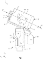
- the figure 1 and 2 are schematic views, respectively two-dimensional and in perspective, of the disinfection apparatus 1 according to a first embodiment, the latter being represented along a longitudinal section plane passing through the longitudinal axis ⁇ .
- the disinfection device 1 comprises the disinfection enclosure 10 adapted to receive an element to be disinfected, here a hand of a user, a nebulization device 20 adapted to generate the disinfectant aerosol intended to be deposited on the hand present in the disinfection chamber 10, and an injection device 30 suitable for injecting the aerosol thus formed into the disinfection chamber 10. It advantageously comprises a collection device 40 adapted to collect the disinfectant aerosol or the disinfectant liquid present in the disinfection enclosure 10, but which has not been used.
- the disinfection enclosure 10 is spatially delimited by a wall 11, and extends longitudinally along the axis ⁇ . This comprises an inlet opening 12 through which the user's hand is introduced into the disinfection enclosure 10, and an outlet opening 13 opposite the inlet opening 12 along the longitudinal axis ⁇ . It has a cross section, orthogonal to the longitudinal axis ⁇ , of circular shape. As a variant, it may have other shapes, for example oval, or even polygonal, such as square, rectangular or other.
- the disinfection enclosure 10 may have an inclined orientation with respect to the axis of gravity, such that the inlet 12 is arranged lower than the outlet 13 along the Z axis.
- the wall 11 can then include a collection orifice 43 fluidly connected to a reservoir 44 of a collection device 40.
- the collection orifice 43 is adapted to collect the aerosol that may have deposited on the internal surface of the wall 11 and having coalesced in the form of drops.
- the collection orifice 43 is then placed in a so-called lower zone of the wall 11 along the Z axis, under the inlet 12, so that such drops can thus flow under the effect of gravity until to join the collection orifice 43.
- the disinfection enclosure 10 further comprises at least one air injection orifice 37 through which air is injected into the enclosure 10 so as to generate a rotary air flow around the longitudinal axis ⁇ , and at least one aerosol injection orifice 33 through which the generated aerosol is introduced into the enclosure 10.
- the injection orifice 37 of air and the aerosol injection orifice 33 are here separate from each other.
- the nebulization device 20 is suitable for transforming into an aerosol a solution initially in the continuous liquid phase, the aerosol then being intended to be introduced into the disinfection enclosure 10.
- it comprises a nebulization chamber 21, a tank 23 of disinfectant, and a nebulizer 24.
- the nebulization chamber 21 is delimited by a wall 22 and is partially filled with the disinfectant liquid. It is fluidly connected to the reservoir 23 by a conduit, the reservoir 23 making it possible to maintain constant the height of disinfectant liquid in the nebulization chamber 21.
- the disinfectant liquid can be, by way of examples, a hydro-alcoholic solution, a solution based on sodium hypochlorite or povidone iodine, a solution based on ammonium chloride and amine oxide, ozonated water, or any other disinfectant solution that can be nebulized.
- the nebulizer 24 is of the piezoelectric type with an ultrasonic vibrating membrane. It thus comprises a membrane to be vibrated and a piezoelectric element (not shown), for example a ceramic, making it possible to vibrate the membrane by transforming an excitation voltage into vibration.
- the vibrating membrane is thus bonded to the ceramic, itself being assembled to a housing.
- the nebulizer housing 24 is placed in the nebulization chamber 21 so that the surface of the liquid covers the vibrating membrane.
- the vibration of the membrane by piezoelectric effect causes the formation of the aerosol by ultrasound transmission, the aerosol formed then being composed of droplets of the disinfectant liquid.
- the droplets have an average size advantageously less than a few tens of microns, for example 30 ⁇ m, and preferably less than or equal to 15 ⁇ m.
- the average size of the droplets can be of the order of 5 ⁇ m to 10 ⁇ m approximately.
- Such a nebulizer 24 is known to those skilled in the art and is not described in more detail.
- nebulizers can, as a variant, be used, for example Venturi effect nebulizers, or piezoelectric membrane nebulizers vibrating hole through which a liquid flows and is transformed into an aerosol by the vibration of the membrane.
- Venturi effect nebulizers or piezoelectric membrane nebulizers vibrating hole through which a liquid flows and is transformed into an aerosol by the vibration of the membrane.
- piezoelectric membrane nebulizers vibrating hole through which a liquid flows and is transformed into an aerosol by the vibration of the membrane.
- An example of such a nebulizer is described in particular in the document FR2886174 .
- the injection device 30 is adapted, on the one hand, to introduce into the disinfection chamber 10 the aerosol formed by the nebulization device 20, and on the other hand, to generate by forced convection a flow of air , then entraining the aerosol present, in a rotary manner around the longitudinal axis ⁇ .
- the injection device 30 comprises one or more air injectors 35, and one or more aerosol injectors 31 separate from the air injectors 35. It comprises an air injector 35 and an aerosol injector 31.
- the air injector 35 and the aerosol injector 31 each comprise forced convection means suitable for generating a flow of air and/or aerosol through one or more injection orifices 33, 37 of the wall 11 of the disinfection enclosure 10.
- the forced convection means can be motorized, and include a moving part, such as blades or a propeller, driven in rotation. It is advantageously a fan, the axis of the forced air flow (and therefore the direction of injection) of which is defined by the orientation of the fan and/or by the presence of a air (not shown) located downstream of the fan.
- the air duct can be a fin arranged in such a way as to direct the forced air flow in a determined direction of injection.
- the fan can have an electrical power of a few watts, for example of the order of 1 watt, and cause a forced air flow. Thus, it has low power consumption while providing good air injection efficiency. It can have a small footprint and low operating noise.
- the air injector may include a fan, or equivalent, arranged at the level of the injection orifice 37, the airflow axis of which is oriented so that the direction of injection D, in projection in a plane perpendicular to the axis ⁇ , is inclined with respect to the position axis OP, preferably by an angle of inclination greater than or equal to 10°, or even 20°, for example at 30° or 40°, or even more.
- the fan may be present upstream of the injection orifice 37, in which case the injection duct 34 is oriented and opens at the level of the injection orifice 37 so that the direction of injection D is inclined as previously specified.
- the injection direction D can also be defined by an air duct located at injection port 37.
- the aerosol injector 31 comprises a forced convection means 32 and an injection duct 34 fluidically connecting the nebulization chamber 21 to an aerosol injection orifice 33 .
- the forced convection means here is a fan 32 arranged vis-à-vis the nebulization chamber 21 so as to blow air into it, and therefore to induce an overpressure therein.
- the fan 32 is here located in an inlet duct 25 communicating with an orifice located in an upper part of the wall 22 of the nebulization chamber 21.
- the air flow induced by the fan 32 causes a flow of the aerosol generated, from the nebulization chamber 21, in the injection duct 34, to the injection orifice 33, so as to be introduced into the disinfection chamber 10.
- the aerosol injection conduit 34 advantageously does not have any singular pressure drops, induced for example by a sudden change in orientation, liable to cause local coalescence of part of the aerosol.
- the nebulization chamber 21 and the injection orifice 33 are mutually arranged so that the injection duct 34 is substantially straight.
- the air injector 35 (cf. figure 2 ) comprises a forced convection means 36, here a fan, assembled to the wall 11 of the disinfection enclosure 10 and placed in, or at the injection orifice 37 of air.
- the fan 36 has an inclined air injection direction D, in projection in a plane perpendicular to the longitudinal axis ⁇ , with respect to the corresponding position axis OP, said position axis being orthogonal to the longitudinal axis ⁇ , and passing through said longitudinal axis ⁇ and the injection orifice 37 of air.
- the injection direction D forms, in projection in the plane perpendicular to the axis ⁇ , a non-zero angle of inclination with respect to the position axis OP.
- the sign of the angle of inclination ⁇ i is defined according to the counterclockwise direction in a plane (u x ,u z ) of a reference (u x ,u y ,u z ) in cylindrical coordinates where the vector u y is collinear with the longitudinal axis ⁇ and oriented towards the outlet 13.
- the plane (u x ,u z ) is thus a plane perpendicular to the longitudinal axis ⁇ .
- the angle of inclination is strictly greater than 0°, and is preferably greater than 10° or even 20°, for example substantially equal to 30°, or even more.
- the figures 3B and 3C illustrate variants of the disinfection apparatus 1 according to the first embodiment, which differ from the apparatus shown in the Figure 3A in particular in that the injection device 30 comprises several air injectors 35.
- the angles of inclination of the air injectors 35 advantageously have the same sign, in the plane (u x , u z ) perpendicular to the longitudinal axis ⁇ , so as to reinforce the rotary nature of the air flow, then driving the aerosol, around the longitudinal axis ⁇ .
- the Figure 3B schematically illustrates a disinfection enclosure 10 of oval cross section, in a section plane parallel to the plane (u x , u z ).
- the injection device 30 comprises a single aerosol injector 31 and two air injectors 35 with fans.
- a first fan 36 1 has an injection direction D 1 which, in projection in a plane perpendicular to the longitudinal axis ⁇ , forms an angle of inclination ⁇ 1 with respect to the position axis carried by the vector P 1 O, here around +60°.
- the second fan 36 2 has an injection direction D 2 which, in projection in a plane perpendicular to the longitudinal axis ⁇ , forms an angle of inclination ⁇ 2 with respect to the corresponding position axis carried by the vector P 2 O, here also of the order of +60°.
- the angles of inclination ⁇ 1 , ⁇ 2 can have different values, but have the same sign, so that the forced convection in the disinfection enclosure 10 is indeed rotatable around the longitudinal axis ⁇ .
- the Fig. 3C schematically illustrates a disinfection chamber 10 of rectangular cross-section with rounded corners, in the section plane (u x , u z ) orthogonal to the longitudinal axis ⁇ .
- the injection device 30 comprises two aerosol injectors 31 and two air injectors 35 comprising fans.
- a first fan 36 1 has an injection direction D 1 which forms, in projection in a plane perpendicular to the longitudinal axis ⁇ , an angle of inclination ⁇ 1 with respect to the position axis carried by the vector P 1 O, here of the order of +30°.
- the second fan 36 2 has an injection direction D 2 which forms, in projection in a plane perpendicular to the longitudinal axis ⁇ , an angle of inclination ⁇ 2 with respect to the corresponding position axis carried by the vector P 2 O, here also of the order of +30°.
- the angles of inclination ⁇ 1 , ⁇ 2 being of the same sign, the flow of air forced into the disinfection enclosure 10 is indeed rotatable around the longitudinal axis ⁇ .
- the injection device 30 comprises additional means 39 of forced convection adapted to induce in the disinfection enclosure 10 a flow of air going from the inlet 12 to the outlet 13.
- These forced convection means 39 can be one or more fans, placed at the inlet 12 and/or at the outlet 13 of the disinfection enclosure 10.
- a fan 39 is assembled to the wall 11 of the disinfection enclosure 10 at the level of the outlet 13, and here placed outside the enclosure 10. It makes it possible to suck the air present in the disinfection enclosure 10 towards the outlet 13.
- the aerosol in addition to the rotary flow of the aerosol around of the longitudinal axis ⁇ , the aerosol also flows in a directed manner towards the outlet 13, which makes it possible to limit the risks of loss of the aerosol by diffusion of the latter outside the disinfection enclosure 10 by the inlet opening 12, while improving the homogeneity of the deposition of the aerosol on the surface of the by hand.
- the disinfection device 1 comprises a collection device 40 suitable for recovering the disinfectant liquid or the aerosol not deposited on the user's hand.
- the collection device 40 comprises in this example a condensation filter 41 placed at the outlet 13 and outside the disinfection enclosure 10, here between the wall 11 and the fan 39 outlet.
- a pipe 42 fluidically connects the condensation filter 41 to a collection tank 44.
- the aerosol not deposited on the hand flows to the outlet 13 and is captured by the filter 41.
- the microdroplets coalesce in the filter 41, and the liquid formed flows by gravity in line 42 to tank 44.
- the collection device 40 further comprises at least one collection orifice 43 passing through the wall 11, and placed in a lower zone of the disinfection enclosure 10, under the inlet 12.
- the liquid formed can flow by gravity into the disinfection enclosure 10, and be collected by the collection orifice 43.
- the liquid then flows through the conduit 42 to the reservoir 44.
- the collected liquid can then undergo a treatment with the aim of being subsequently reused.
- the disinfection device 1 comprises a device for detecting (not shown) the presence of an element to be disinfected in the disinfection enclosure 10.
- the detection device may comprise an optical sensor, for example a photodiode, adapted to measure a variation of an optical characteristic of the disinfection enclosure 10, the variation being representative of the presence or not of the element to be disinfected.
- the detection device comprises a control unit making it possible to activate and deactivate the nebulization device 20 and the injection device 30.
- One or more elements to be disinfected for example a hand of a user, are introduced into the disinfection chamber 10.
- the hand is introduced so as to be placed substantially collinear with the longitudinal axis ⁇ .
- the presence detector detects the presence of the hand inside the disinfection enclosure 10, and activates the nebulization device 20.
- the piezoelectric nebulizer 24 then causes the nebulization of the disinfectant liquid in the nebulization chamber 21.
- the liquid disinfectant is then transformed from a continuous liquid phase into an aerosol which forms in the spray chamber 21.
- the injection device 30 is activated, simultaneously or slightly delayed vis-à-vis the activation of the nebulization device 20.
- the fan 36 then causes a flow of air entering the nebulization chamber 21, which causes the aerosol to flow into the injection duct 34, and to be introduced into the disinfection enclosure 10 through the injection orifice 33, here substantially in the direction of the longitudinal axis ⁇ .
- the hand remains free to move in the disinfection chamber 10, thus improving the rate of coverage by the disinfectant aerosol. Furthermore, the rate of coverage of the hand by the aerosol is high, without it being necessary to use several aerosol injectors distributed around the longitudinal axis ⁇ , and without it being necessary to provide a spreader requiring the user to spread the fingers of the hand.
- the outlet fan 39 is activated, which causes additional forced convection in the disinfection enclosure 10, going from the inlet 12 to the outlet 13.
- the aerosol while rotating around the axis longitudinal ⁇ to be deposited on substantially the entire surface of the hand, flows in the direction of the outlet 13, thus limiting the loss of the aerosol by diffusion thereof out of the enclosure 10 through the opening input 12 while improving the uniformity of the deposition of the aerosol on the surface of the hand.
- Unused aerosol is collected by condensation filter 41 and flows through conduit 42 to collection tank 44.
- the droplets having deposited on the inner surface of the wall 11 and having coalesced can flow to the collection orifice 43, to then flow to the tank 44.
- the unused disinfectant liquid is thus recovered to then, after treatment, be advantageously reused.
- the control unit withdraws his hand from the disinfection enclosure 10, and the nebulization 20 and injection 30 devices can be deactivated.
- a preliminary phase of drying the hand by sending a flow of hot air can also be provided.
- the figure 4 schematically illustrates a disinfection device 1 according to a variant of the first embodiment.
- the disinfection device 1 differs from that illustrated on the figure 1 and 2 essentially in that the nebulization chamber 21 and the disinfection enclosure 10 are no longer delimited by two distinct walls 11, 22, but are here separated from each other by the same wall 11.
- the separation wall 11 comprises at least one aerosol injection orifice 33, and here a plurality of injection orifices 33, passing through the wall 11 so as to allow the aerosol to pass into the nebulization chamber 21 directly in the disinfection enclosure 10.
- the nebulization chamber 21 is thus no longer fluidly connected to the disinfection enclosure 10 by an aerosol injection conduit 34 formed for example of a flexible or rigid pipe. This limits the possible pressure drops associated with such conduits, in particular the singular pressure drops formed by the sudden changes in orientation of the conduits likely to disturb the injection of the aerosol into the disinfection chamber 10.
- the fan 32 causes a flow of air entering the nebulization chamber 21, which induces the introduction of the aerosol into the disinfection enclosure 10 through injection ports 33.
- the collection tank 44 is located on the side of the outlet 13 of the disinfection enclosure 10 and no longer on the side of the inlet 12 of the latter, thus making it possible to improve the compactness of the disinfection device 1.
- the figure 5 illustrates another variant of the disinfection device 1 according to the first embodiment.
- the injection device comprises several sets of aerosol injection orifices, here two sets 33 1 , 33 2 , each set being connected to the nebulization chamber 21 by a separate conduit 34 1 , 34 2 .
- the two sets 33 1 and 33 2 are here arranged substantially symmetrically with respect to a plane passing through the axis ⁇ .
- the orifices 33 of each set 33 1 , 33 2 are arranged along the axis ⁇ .
- the fig.5 more particularly illustrates the duct 34 2 connecting the chamber 21 to the set of orifices 33 2 .
- the fan 32 and the inlet duct 25 can be located between the two ducts 34 1 and 34 2 .
- the other elements of the disinfection device 1 are identical or similar to those already described and are not detailed in the new.
- This arrangement of the sets of orifices 33 1 , 33 2 and their fluidic connection to the chamber 21 make it possible in particular to obtain a greater flow rate of aerosol injected into the disinfection enclosure and/or a more homogeneous injection into the enclosure. 10.
- the figure 6 schematically illustrates a disinfection device 1 according to a second embodiment.
- the disinfection device 1 differs from that illustrated in the figure 1 and 2 essentially in that the injection device 30 comprises at least one aerosol injector 35 adapted to also inject air to generate a flow of rotating aerosol around the longitudinal axis ⁇ .
- the injection device 30 comprises, in addition to an aerosol injector 31 identical or similar to that present in the disinfection device 1 according to the first embodiment, at least one air injector 35 and aerosol having a inclined direction of inclination D, in projection in a plane perpendicular to the longitudinal axis ⁇ and vis-à-vis the corresponding position axis OP, this position axis being orthogonal to the longitudinal axis ⁇ , and passing through said longitudinal axis ⁇ and the injection orifice considered.
- This air and aerosol injector 35 is formed by a duct 34 connecting the nebulization chamber 21 and opening into the disinfection enclosure 10 through the injection orifice 33.
- the injection duct 34 is oriented, at the injection orifice 33, so that its longitudinal axis coincides with the desired direction of injection.
- the fan 32 causes a flow of air entering the nebulization chamber 21, which induces the introduction of the aerosol into the disinfection enclosure 10 by the aerosol injector 31 on the one hand, and by the air injector 35 and aerosol on the other hand.
- the rotating flow is then obtained in the disinfection enclosure 10.
- the figures 7B and 7C illustrate variants of the disinfection apparatus 1 according to the second embodiment, which differ from the apparatus shown in the Figure 7A in particular in that the injection device 30 comprises several air and aerosol injectors 35 .
- the angles of inclination of the air and aerosol injectors 35 advantageously have the same sign, in the plane (u x , u z ) perpendicular to the longitudinal axis ⁇ , so as to reinforce the rotary character from flow of air, and therefore of aerosol, around the longitudinal axis ⁇ .
- the injection device 30 comprises a single aerosol injector 31 and two air and aerosol injectors 35 .
- the aerosol injector 31 does not participate in generating a rotary airflow around the longitudinal axis ⁇ insofar as its direction of injection is substantially secant of the axis ⁇ .
- the two aerosol and air injectors 35 not only introduce the aerosol into the enclosure 10, but generate a rotating air flow insofar as their direction of injection is inclined, projecting in a perpendicular plane. to the axis ⁇ and with respect to their proper position axis, and insofar as the angles of inclination are of the same sign.
- a first air and aerosol injector 35 1 has an injection direction D 1 which forms an angle of inclination ⁇ 1 with respect to the position axis carried by the vector P 1 O, here l order of +40° approximately.
- the second air and aerosol injector 35 2 has an injection direction D 2 which forms an angle of inclination ⁇ 2 with respect to the corresponding position axis carried by the vector P 2 O, here also l order of +30°.
- the angles of inclination have the same sign, so that the forced convection in the disinfection enclosure 10 is indeed rotatable around the longitudinal axis ⁇ .
- the element to be disinfected can be other members of a user, for example the foot, or even be an object introduced and held by the user in the disinfection enclosure 10.
Landscapes
- Health & Medical Sciences (AREA)
- Public Health (AREA)
- General Health & Medical Sciences (AREA)
- Life Sciences & Earth Sciences (AREA)
- Animal Behavior & Ethology (AREA)
- Epidemiology (AREA)
- Veterinary Medicine (AREA)
- Chemical & Material Sciences (AREA)
- Chemical Kinetics & Catalysis (AREA)
- General Chemical & Material Sciences (AREA)
- Surgery (AREA)
- Engineering & Computer Science (AREA)
- Oral & Maxillofacial Surgery (AREA)
- Nuclear Medicine, Radiotherapy & Molecular Imaging (AREA)
- Pathology (AREA)
- Mechanical Engineering (AREA)
- Biomedical Technology (AREA)
- Heart & Thoracic Surgery (AREA)
- Medical Informatics (AREA)
- Molecular Biology (AREA)
- Apparatus For Disinfection Or Sterilisation (AREA)
Claims (10)
- Desinfektionsvorrichtung (1) aufweisend:o einen Desinfektionsraum (10), der von einer Wand (11) mit einer Einlassöffnung (12), durch die ein zu desinfizierendes Element eingeführt werden kann, und einer Auslassöffnung (13) gegenüber der Einlassöffnung (12) entlang einer Längsachse (Δ) begrenzt wird, entlang welcher sich die Wand (11) in Längsrichtung erstreckt;o eine Zerstäubungsvorrichtung (20), die geeignet ist, ein aerosolförmiges Desinfektionsmittel zu zerstäuben;o eine Einspritzvorrichtung (30), aufweisend:• wenigstens einen Aerosoleinspritzer (31), der geeignet ist, in den Desinfektionsraum (10) das Aerosol einzuspritzen, das von der Zerstäubungsvorrichtung (20) gebildet wird;dadurch gekennzeichnet, dass die Einspritzvorrichtung (30) ferner Folgendes aufweist:• wenigstens einen Lufteinspritzer (35), der geeignet ist, Luft durch eine Einspritzöffnung (37) der Wand (11) in einer Einspritzrichtung (D) einzuspritzen und eine erzwungene Konvektion im Desinfektionsraum (10) und um die Längsachse (Δ) drehend zu erzeugen, wobei der Lufteinspritzer (35) so angeordnet ist, dass die Einspritzrichtung (D) in Projektion in einer Ebene senkrecht zur Längsachse (Δ) bezogen auf eine Positionsachse (PO) geneigt ist, wobei die Positionsachse (PO) senkrecht zur Längsachse (Δ) und durch die Einspritzöffnung (37) des Lufteinspritzers (35) verläuft.
- Desinfektionsvorrichtung (1) nach Anspruch 1, wobei die Einspritzvorrichtung (30) ferner ein Mittel für erzwungene Konvektion (39) aufweist, das gegenüber dem Desinfektionsraum (10) so angeordnet ist, dass eine Luftströmung von der Einlassöffnung (12) zur Auslassöffnung (13) erzeugt wird.
- Desinfektionsvorrichtung (1) nach Anspruch 1 oder 2, wobei die Einspritzvorrichtung (30) wenigstens einen Lufteinspritzer (35) und wenigstens einen Aerosoleinspritzer (31), der vom Lufteinspritzer (35) gesondert ist, aufweist.
- Desinfektionsvorrichtung (1) nach Anspruch 1 oder 2, wobei die Einspritzvorrichtung (30) wenigstens einen Luft- und Aerosoleinspritzer (35) aufweist, der geeignet ist, den Lufteinspritzer (35) und den Aerosoleinspritzer (31) zu bilden.
- Desinfektionsvorrichtung (1) nach einem der Ansprüche 1 bis 4, aufweisend eine Mehrzahl von Lufteinspritzern (35), die jeweils in Projektion in der Ebene senkrecht zur Längsachse (Δ) einen Neigungswinkel (θ) ungleich null aufweisen, der von seiner Einspritzrichtung (D) bezogen auf seine Positionsachse (PO) gebildet wird, wobei die Neigungswinkel vorzeichengleich sind.
- Desinfektionsvorrichtung (1) nach einem der Ansprüche 1 bis 5, wobei sich ein Filter (41), der geeignet ist, das Aerosol aufzufangen, gegenüber der Auslassöffnung (13) des Desinfektionsraums (10) befindet.
- Desinfektionsvorrichtung (1) nach einem der Ansprüche 1 bis 6, wobei der Desinfektionsraum (10) so angeordnet ist, dass die Längsachse (Δ) bezogen auf die Achse der Schwerkraft geneigt ist, wobei sich die Auslassöffnung (13) über der Einlassöffnung (12) befindet.
- Desinfektionsvorrichtung (1) nach einem der Ansprüche 1 bis 7, wobei der Lufteinspritzer (35) einen Ventilator (36) aufweist.
- Desinfektionsvorrichtung (1) nach einem der Ansprüche 1 bis 8, wobei die Zerstäubungsvorrichtung (20) eine Zerstäubungskammer (21) mit einer flüssigen Desinfektionslösung aufweist, in der sich ein Zerstäuber (24) befindet, der geeignet ist, die flüssige Desinfektionslösung zu Aerosol zu zerstäuben, wobei der Aerosoleinspritzer (31) wenigstens eine Einspritzleitung (34) aufweist, die die Zerstäubungskammer (21) fluidisch mit dem Desinfektionsraum (10) verbindet.
- Desinfektionsvorrichtung (1) nach einem der Ansprüche 1 bis 8, wobei die Zerstäubungsvorrichtung (20) eine Zerstäubungskammer (21) mit einer flüssigen Desinfektionslösung aufweist, in der sich ein Zerstäuber (24) befindet, der geeignet ist, die flüssige Desinfektionslösung zu Aerosol zu zerstäuben, wobei die Zerstäubungskammer (21) und der Desinfektionsraum (10) jeweils wenigstens teilweise von ein und derselben Wand (11) begrenzt sind, die wenigstens eine durchgehende Einspritzöffnung (33) aufweist, die den Durchtritt des Aerosols von der Zerstäubungskammer (21) in den Desinfektionsraum (10) ermöglicht.
Applications Claiming Priority (2)
| Application Number | Priority Date | Filing Date | Title |
|---|---|---|---|
| FR1754122A FR3066093B1 (fr) | 2017-05-11 | 2017-05-11 | Appareil de desinfection par nebulisation |
| PCT/FR2018/051156 WO2018206899A1 (fr) | 2017-05-11 | 2018-05-09 | Appareil de desinfection par nebulisation |
Publications (2)
| Publication Number | Publication Date |
|---|---|
| EP3621504A1 EP3621504A1 (de) | 2020-03-18 |
| EP3621504B1 true EP3621504B1 (de) | 2022-11-09 |
Family
ID=59153166
Family Applications (1)
| Application Number | Title | Priority Date | Filing Date |
|---|---|---|---|
| EP18728439.3A Active EP3621504B1 (de) | 2017-05-11 | 2018-05-09 | Desinfektionsvorrichtung unter verwendung von vernebelung |
Country Status (3)
| Country | Link |
|---|---|
| EP (1) | EP3621504B1 (de) |
| FR (1) | FR3066093B1 (de) |
| WO (1) | WO2018206899A1 (de) |
Families Citing this family (3)
| Publication number | Priority date | Publication date | Assignee | Title |
|---|---|---|---|---|
| CN109513033A (zh) * | 2018-12-19 | 2019-03-26 | 温州维科生物实验设备有限公司 | 冷蒸发灭菌装置 |
| FR3116202A1 (fr) | 2020-11-18 | 2022-05-20 | Evercleanhand | Appareil de désinfection avec dispositif de collecte |
| DE102020131057B4 (de) | 2020-11-24 | 2025-08-28 | VIP HYGIENE k.s. | Handtrocknungssystem und Handreinigungssystem |
Family Cites Families (4)
| Publication number | Priority date | Publication date | Assignee | Title |
|---|---|---|---|---|
| US3918987A (en) * | 1973-11-09 | 1975-11-11 | Rudolph J Kopfer | Surgeon hand and arm scrubbing apparatus |
| FR2886174B1 (fr) | 2005-05-25 | 2007-08-10 | Oreal | Dispositif de pulverisation piezoelectrique |
| FR2955030B1 (fr) | 2010-01-14 | 2012-03-02 | Bernard Feldain | Appareil pour la desinfection des mains d'un usager. |
| DE102012008253A1 (de) * | 2012-04-25 | 2013-10-31 | Ushio Europe B.V. | Trockner, insbesondere Handtrockner |
-
2017
- 2017-05-11 FR FR1754122A patent/FR3066093B1/fr not_active Expired - Fee Related
-
2018
- 2018-05-09 WO PCT/FR2018/051156 patent/WO2018206899A1/fr not_active Ceased
- 2018-05-09 EP EP18728439.3A patent/EP3621504B1/de active Active
Also Published As
| Publication number | Publication date |
|---|---|
| WO2018206899A1 (fr) | 2018-11-15 |
| FR3066093B1 (fr) | 2019-06-14 |
| EP3621504A1 (de) | 2020-03-18 |
| FR3066093A1 (fr) | 2018-11-16 |
Similar Documents
| Publication | Publication Date | Title |
|---|---|---|
| CA2955409C (fr) | Nebuliseur compact pour rafraichir l'air | |
| EP3621504B1 (de) | Desinfektionsvorrichtung unter verwendung von vernebelung | |
| EP0437155B1 (de) | Verfahren zur Ultraschallzerstäubung einer Flüssigkeitslösung und Tröpfchendiffusor zur Durchführung dieses Verfahrens | |
| EP3481442B1 (de) | Vorrichtung zur vernebelung einer flüssigkeit, verfahren zur desinfektion durch luftwege und verwendung dieser vorrichtung zur desinfektion durch luftwege | |
| EP2991773B1 (de) | Vernebelungsvorrichtung zum kühlen von luft | |
| EP1007220A1 (de) | Vernebelungskopf- und vorrichtung | |
| EP3389874B1 (de) | Piezoelektrische wandler-sprühvorrichtung, insbesondere für ein fahrzeug | |
| EP2448682A1 (de) | Zweiphasen-sprühdüse und verdampfungsvorrichtung damit | |
| EP2804647B1 (de) | Verneblervorrichtung für medizinische aerosole | |
| EP3681644B1 (de) | Vorrichtung zur erzeugung von tröpfchen aus einer flüssigkeit mit verbesserten mitteln zur diffusion des nebels und verfahren zur implementierung davon | |
| EP3227622B1 (de) | Kompakte sprühvorrichtung | |
| FR2967915A1 (fr) | Dispositif d'evaporation | |
| FR3026646B1 (fr) | Dispositif de nebulisation a tamis fixe | |
| FR3018039A1 (fr) | Systeme d'exposition aux allergenes comprenant une chambre de melange entre l'air et les allergenes, separee de la salle d'exposition accueillant les patients | |
| EP3681645B1 (de) | Vorrichtung zur erzeugung von tröpfchen aus einer flüssigkeit mit verbesserten ventilationsmitteln und verfahren zur implementierung derselben | |
| FR2781678A1 (fr) | Appareil de diffusion d'un produit liquide tel qu'un desinfectant pour le traitement de locaux ou de surfaces par voie aerienne | |
| EP4000654A1 (de) | Desinfektionsgerät mit flüssigkeitssammelvorrichtung | |
| WO2021260284A1 (fr) | Dispositif de traitement de l'air contenu dans un volume peripherique |
Legal Events
| Date | Code | Title | Description |
|---|---|---|---|
| STAA | Information on the status of an ep patent application or granted ep patent |
Free format text: STATUS: UNKNOWN |
|
| STAA | Information on the status of an ep patent application or granted ep patent |
Free format text: STATUS: THE INTERNATIONAL PUBLICATION HAS BEEN MADE |
|
| PUAI | Public reference made under article 153(3) epc to a published international application that has entered the european phase |
Free format text: ORIGINAL CODE: 0009012 |
|
| STAA | Information on the status of an ep patent application or granted ep patent |
Free format text: STATUS: REQUEST FOR EXAMINATION WAS MADE |
|
| 17P | Request for examination filed |
Effective date: 20191101 |
|
| AK | Designated contracting states |
Kind code of ref document: A1 Designated state(s): AL AT BE BG CH CY CZ DE DK EE ES FI FR GB GR HR HU IE IS IT LI LT LU LV MC MK MT NL NO PL PT RO RS SE SI SK SM TR |
|
| AX | Request for extension of the european patent |
Extension state: BA ME |
|
| DAV | Request for validation of the european patent (deleted) | ||
| DAX | Request for extension of the european patent (deleted) | ||
| GRAP | Despatch of communication of intention to grant a patent |
Free format text: ORIGINAL CODE: EPIDOSNIGR1 |
|
| STAA | Information on the status of an ep patent application or granted ep patent |
Free format text: STATUS: GRANT OF PATENT IS INTENDED |
|
| INTG | Intention to grant announced |
Effective date: 20220531 |
|
| GRAS | Grant fee paid |
Free format text: ORIGINAL CODE: EPIDOSNIGR3 |
|
| GRAA | (expected) grant |
Free format text: ORIGINAL CODE: 0009210 |
|
| STAA | Information on the status of an ep patent application or granted ep patent |
Free format text: STATUS: THE PATENT HAS BEEN GRANTED |
|
| AK | Designated contracting states |
Kind code of ref document: B1 Designated state(s): AL AT BE BG CH CY CZ DE DK EE ES FI FR GB GR HR HU IE IS IT LI LT LU LV MC MK MT NL NO PL PT RO RS SE SI SK SM TR |
|
| REG | Reference to a national code |
Ref country code: GB Ref legal event code: FG4D Free format text: NOT ENGLISH |
|
| REG | Reference to a national code |
Ref country code: CH Ref legal event code: EP Ref country code: AT Ref legal event code: REF Ref document number: 1529800 Country of ref document: AT Kind code of ref document: T Effective date: 20221115 |
|
| REG | Reference to a national code |
Ref country code: DE Ref legal event code: R096 Ref document number: 602018042839 Country of ref document: DE |
|
| REG | Reference to a national code |
Ref country code: IE Ref legal event code: FG4D Free format text: LANGUAGE OF EP DOCUMENT: FRENCH |
|
| REG | Reference to a national code |
Ref country code: LT Ref legal event code: MG9D |
|
| REG | Reference to a national code |
Ref country code: NL Ref legal event code: MP Effective date: 20221109 |
|
| REG | Reference to a national code |
Ref country code: AT Ref legal event code: MK05 Ref document number: 1529800 Country of ref document: AT Kind code of ref document: T Effective date: 20221109 |
|
| PG25 | Lapsed in a contracting state [announced via postgrant information from national office to epo] |
Ref country code: SE Free format text: LAPSE BECAUSE OF FAILURE TO SUBMIT A TRANSLATION OF THE DESCRIPTION OR TO PAY THE FEE WITHIN THE PRESCRIBED TIME-LIMIT Effective date: 20221109 Ref country code: PT Free format text: LAPSE BECAUSE OF FAILURE TO SUBMIT A TRANSLATION OF THE DESCRIPTION OR TO PAY THE FEE WITHIN THE PRESCRIBED TIME-LIMIT Effective date: 20230309 Ref country code: NO Free format text: LAPSE BECAUSE OF FAILURE TO SUBMIT A TRANSLATION OF THE DESCRIPTION OR TO PAY THE FEE WITHIN THE PRESCRIBED TIME-LIMIT Effective date: 20230209 Ref country code: LT Free format text: LAPSE BECAUSE OF FAILURE TO SUBMIT A TRANSLATION OF THE DESCRIPTION OR TO PAY THE FEE WITHIN THE PRESCRIBED TIME-LIMIT Effective date: 20221109 Ref country code: FI Free format text: LAPSE BECAUSE OF FAILURE TO SUBMIT A TRANSLATION OF THE DESCRIPTION OR TO PAY THE FEE WITHIN THE PRESCRIBED TIME-LIMIT Effective date: 20221109 Ref country code: ES Free format text: LAPSE BECAUSE OF FAILURE TO SUBMIT A TRANSLATION OF THE DESCRIPTION OR TO PAY THE FEE WITHIN THE PRESCRIBED TIME-LIMIT Effective date: 20221109 Ref country code: AT Free format text: LAPSE BECAUSE OF FAILURE TO SUBMIT A TRANSLATION OF THE DESCRIPTION OR TO PAY THE FEE WITHIN THE PRESCRIBED TIME-LIMIT Effective date: 20221109 |
|
| PG25 | Lapsed in a contracting state [announced via postgrant information from national office to epo] |
Ref country code: RS Free format text: LAPSE BECAUSE OF FAILURE TO SUBMIT A TRANSLATION OF THE DESCRIPTION OR TO PAY THE FEE WITHIN THE PRESCRIBED TIME-LIMIT Effective date: 20221109 Ref country code: PL Free format text: LAPSE BECAUSE OF FAILURE TO SUBMIT A TRANSLATION OF THE DESCRIPTION OR TO PAY THE FEE WITHIN THE PRESCRIBED TIME-LIMIT Effective date: 20221109 Ref country code: LV Free format text: LAPSE BECAUSE OF FAILURE TO SUBMIT A TRANSLATION OF THE DESCRIPTION OR TO PAY THE FEE WITHIN THE PRESCRIBED TIME-LIMIT Effective date: 20221109 Ref country code: IS Free format text: LAPSE BECAUSE OF FAILURE TO SUBMIT A TRANSLATION OF THE DESCRIPTION OR TO PAY THE FEE WITHIN THE PRESCRIBED TIME-LIMIT Effective date: 20230309 Ref country code: HR Free format text: LAPSE BECAUSE OF FAILURE TO SUBMIT A TRANSLATION OF THE DESCRIPTION OR TO PAY THE FEE WITHIN THE PRESCRIBED TIME-LIMIT Effective date: 20221109 Ref country code: GR Free format text: LAPSE BECAUSE OF FAILURE TO SUBMIT A TRANSLATION OF THE DESCRIPTION OR TO PAY THE FEE WITHIN THE PRESCRIBED TIME-LIMIT Effective date: 20230210 |
|
| PG25 | Lapsed in a contracting state [announced via postgrant information from national office to epo] |
Ref country code: NL Free format text: LAPSE BECAUSE OF FAILURE TO SUBMIT A TRANSLATION OF THE DESCRIPTION OR TO PAY THE FEE WITHIN THE PRESCRIBED TIME-LIMIT Effective date: 20221109 |
|
| PG25 | Lapsed in a contracting state [announced via postgrant information from national office to epo] |
Ref country code: SM Free format text: LAPSE BECAUSE OF FAILURE TO SUBMIT A TRANSLATION OF THE DESCRIPTION OR TO PAY THE FEE WITHIN THE PRESCRIBED TIME-LIMIT Effective date: 20221109 Ref country code: RO Free format text: LAPSE BECAUSE OF FAILURE TO SUBMIT A TRANSLATION OF THE DESCRIPTION OR TO PAY THE FEE WITHIN THE PRESCRIBED TIME-LIMIT Effective date: 20221109 Ref country code: EE Free format text: LAPSE BECAUSE OF FAILURE TO SUBMIT A TRANSLATION OF THE DESCRIPTION OR TO PAY THE FEE WITHIN THE PRESCRIBED TIME-LIMIT Effective date: 20221109 Ref country code: DK Free format text: LAPSE BECAUSE OF FAILURE TO SUBMIT A TRANSLATION OF THE DESCRIPTION OR TO PAY THE FEE WITHIN THE PRESCRIBED TIME-LIMIT Effective date: 20221109 Ref country code: CZ Free format text: LAPSE BECAUSE OF FAILURE TO SUBMIT A TRANSLATION OF THE DESCRIPTION OR TO PAY THE FEE WITHIN THE PRESCRIBED TIME-LIMIT Effective date: 20221109 |
|
| PGFP | Annual fee paid to national office [announced via postgrant information from national office to epo] |
Ref country code: FR Payment date: 20230531 Year of fee payment: 6 Ref country code: DE Payment date: 20230526 Year of fee payment: 6 |
|
| REG | Reference to a national code |
Ref country code: DE Ref legal event code: R097 Ref document number: 602018042839 Country of ref document: DE |
|
| PG25 | Lapsed in a contracting state [announced via postgrant information from national office to epo] |
Ref country code: SK Free format text: LAPSE BECAUSE OF FAILURE TO SUBMIT A TRANSLATION OF THE DESCRIPTION OR TO PAY THE FEE WITHIN THE PRESCRIBED TIME-LIMIT Effective date: 20221109 Ref country code: AL Free format text: LAPSE BECAUSE OF FAILURE TO SUBMIT A TRANSLATION OF THE DESCRIPTION OR TO PAY THE FEE WITHIN THE PRESCRIBED TIME-LIMIT Effective date: 20221109 |
|
| PLBE | No opposition filed within time limit |
Free format text: ORIGINAL CODE: 0009261 |
|
| STAA | Information on the status of an ep patent application or granted ep patent |
Free format text: STATUS: NO OPPOSITION FILED WITHIN TIME LIMIT |
|
| 26N | No opposition filed |
Effective date: 20230810 |
|
| PGFP | Annual fee paid to national office [announced via postgrant information from national office to epo] |
Ref country code: GB Payment date: 20230530 Year of fee payment: 6 |
|
| PG25 | Lapsed in a contracting state [announced via postgrant information from national office to epo] |
Ref country code: SI Free format text: LAPSE BECAUSE OF FAILURE TO SUBMIT A TRANSLATION OF THE DESCRIPTION OR TO PAY THE FEE WITHIN THE PRESCRIBED TIME-LIMIT Effective date: 20221109 |
|
| REG | Reference to a national code |
Ref country code: CH Ref legal event code: PL |
|
| PG25 | Lapsed in a contracting state [announced via postgrant information from national office to epo] |
Ref country code: MC Free format text: LAPSE BECAUSE OF FAILURE TO SUBMIT A TRANSLATION OF THE DESCRIPTION OR TO PAY THE FEE WITHIN THE PRESCRIBED TIME-LIMIT Effective date: 20221109 |
|
| REG | Reference to a national code |
Ref country code: BE Ref legal event code: MM Effective date: 20230531 |
|
| PG25 | Lapsed in a contracting state [announced via postgrant information from national office to epo] |
Ref country code: MC Free format text: LAPSE BECAUSE OF FAILURE TO SUBMIT A TRANSLATION OF THE DESCRIPTION OR TO PAY THE FEE WITHIN THE PRESCRIBED TIME-LIMIT Effective date: 20221109 Ref country code: LU Free format text: LAPSE BECAUSE OF NON-PAYMENT OF DUE FEES Effective date: 20230509 Ref country code: LI Free format text: LAPSE BECAUSE OF NON-PAYMENT OF DUE FEES Effective date: 20230531 Ref country code: CH Free format text: LAPSE BECAUSE OF NON-PAYMENT OF DUE FEES Effective date: 20230531 |
|
| REG | Reference to a national code |
Ref country code: IE Ref legal event code: MM4A |
|
| PG25 | Lapsed in a contracting state [announced via postgrant information from national office to epo] |
Ref country code: IE Free format text: LAPSE BECAUSE OF NON-PAYMENT OF DUE FEES Effective date: 20230509 |
|
| PG25 | Lapsed in a contracting state [announced via postgrant information from national office to epo] |
Ref country code: IE Free format text: LAPSE BECAUSE OF NON-PAYMENT OF DUE FEES Effective date: 20230509 |
|
| PG25 | Lapsed in a contracting state [announced via postgrant information from national office to epo] |
Ref country code: IT Free format text: LAPSE BECAUSE OF FAILURE TO SUBMIT A TRANSLATION OF THE DESCRIPTION OR TO PAY THE FEE WITHIN THE PRESCRIBED TIME-LIMIT Effective date: 20221109 Ref country code: BE Free format text: LAPSE BECAUSE OF NON-PAYMENT OF DUE FEES Effective date: 20230531 |
|
| PG25 | Lapsed in a contracting state [announced via postgrant information from national office to epo] |
Ref country code: BG Free format text: LAPSE BECAUSE OF FAILURE TO SUBMIT A TRANSLATION OF THE DESCRIPTION OR TO PAY THE FEE WITHIN THE PRESCRIBED TIME-LIMIT Effective date: 20221109 |
|
| PG25 | Lapsed in a contracting state [announced via postgrant information from national office to epo] |
Ref country code: BG Free format text: LAPSE BECAUSE OF FAILURE TO SUBMIT A TRANSLATION OF THE DESCRIPTION OR TO PAY THE FEE WITHIN THE PRESCRIBED TIME-LIMIT Effective date: 20221109 |
|
| REG | Reference to a national code |
Ref country code: DE Ref legal event code: R119 Ref document number: 602018042839 Country of ref document: DE |
|
| GBPC | Gb: european patent ceased through non-payment of renewal fee |
Effective date: 20240509 |
|
| PG25 | Lapsed in a contracting state [announced via postgrant information from national office to epo] |
Ref country code: DE Free format text: LAPSE BECAUSE OF NON-PAYMENT OF DUE FEES Effective date: 20241203 |
|
| PG25 | Lapsed in a contracting state [announced via postgrant information from national office to epo] |
Ref country code: FR Free format text: LAPSE BECAUSE OF NON-PAYMENT OF DUE FEES Effective date: 20240531 |
|
| PG25 | Lapsed in a contracting state [announced via postgrant information from national office to epo] |
Ref country code: GB Free format text: LAPSE BECAUSE OF NON-PAYMENT OF DUE FEES Effective date: 20240509 |
|
| PG25 | Lapsed in a contracting state [announced via postgrant information from national office to epo] |
Ref country code: CY Free format text: LAPSE BECAUSE OF FAILURE TO SUBMIT A TRANSLATION OF THE DESCRIPTION OR TO PAY THE FEE WITHIN THE PRESCRIBED TIME-LIMIT; INVALID AB INITIO Effective date: 20180509 |
|
| PG25 | Lapsed in a contracting state [announced via postgrant information from national office to epo] |
Ref country code: HU Free format text: LAPSE BECAUSE OF FAILURE TO SUBMIT A TRANSLATION OF THE DESCRIPTION OR TO PAY THE FEE WITHIN THE PRESCRIBED TIME-LIMIT; INVALID AB INITIO Effective date: 20180509 |
|
| PG25 | Lapsed in a contracting state [announced via postgrant information from national office to epo] |
Ref country code: TR Free format text: LAPSE BECAUSE OF FAILURE TO SUBMIT A TRANSLATION OF THE DESCRIPTION OR TO PAY THE FEE WITHIN THE PRESCRIBED TIME-LIMIT Effective date: 20221109 |