EP3621737B1 - Halteklammer und probenrack für ein probenanalysesystem - Google Patents
Halteklammer und probenrack für ein probenanalysesystem Download PDFInfo
- Publication number
- EP3621737B1 EP3621737B1 EP18799382.9A EP18799382A EP3621737B1 EP 3621737 B1 EP3621737 B1 EP 3621737B1 EP 18799382 A EP18799382 A EP 18799382A EP 3621737 B1 EP3621737 B1 EP 3621737B1
- Authority
- EP
- European Patent Office
- Prior art keywords
- engagement member
- sample
- retention clip
- rack
- extends
- Prior art date
- Legal status (The legal status is an assumption and is not a legal conclusion. Google has not performed a legal analysis and makes no representation as to the accuracy of the status listed.)
- Active
Links
Images






Classifications
-
- B—PERFORMING OPERATIONS; TRANSPORTING
- B01—PHYSICAL OR CHEMICAL PROCESSES OR APPARATUS IN GENERAL
- B01L—CHEMICAL OR PHYSICAL LABORATORY APPARATUS FOR GENERAL USE
- B01L9/00—Supporting devices; Holding devices
- B01L9/06—Test-tube stands; Test-tube holders
-
- A—HUMAN NECESSITIES
- A47—FURNITURE; DOMESTIC ARTICLES OR APPLIANCES; COFFEE MILLS; SPICE MILLS; SUCTION CLEANERS IN GENERAL
- A47F—SPECIAL FURNITURE, FITTINGS, OR ACCESSORIES FOR SHOPS, STOREHOUSES, BARS, RESTAURANTS OR THE LIKE; PAYING COUNTERS
- A47F7/00—Show stands, hangers, or shelves, adapted for particular articles or materials
- A47F7/0021—Show stands, hangers, or shelves, adapted for particular articles or materials for long or non-stable articles, e.g. fishing rods, pencils, lipsticks or the like; Compartments or recesses as stabilising means
- A47F7/0028—Show stands, hangers, or shelves, adapted for particular articles or materials for long or non-stable articles, e.g. fishing rods, pencils, lipsticks or the like; Compartments or recesses as stabilising means with one compartment or recess for each article
-
- B—PERFORMING OPERATIONS; TRANSPORTING
- B01—PHYSICAL OR CHEMICAL PROCESSES OR APPARATUS IN GENERAL
- B01L—CHEMICAL OR PHYSICAL LABORATORY APPARATUS FOR GENERAL USE
- B01L3/00—Containers or dishes for laboratory use, e.g. laboratory glassware; Droppers
- B01L3/50—Containers for the purpose of retaining a material to be analysed, e.g. test tubes
- B01L3/508—Rigid containers without fluid transport within
-
- G—PHYSICS
- G01—MEASURING; TESTING
- G01N—INVESTIGATING OR ANALYSING MATERIALS BY DETERMINING THEIR CHEMICAL OR PHYSICAL PROPERTIES
- G01N35/00—Automatic analysis not limited to methods or materials provided for in any single one of groups G01N1/00 - G01N33/00; Handling materials therefor
- G01N35/02—Automatic analysis not limited to methods or materials provided for in any single one of groups G01N1/00 - G01N33/00; Handling materials therefor using a plurality of sample containers moved by a conveyor system past one or more treatment or analysis stations
- G01N35/026—Automatic analysis not limited to methods or materials provided for in any single one of groups G01N1/00 - G01N33/00; Handling materials therefor using a plurality of sample containers moved by a conveyor system past one or more treatment or analysis stations having blocks or racks of reaction cells or cuvettes
-
- G—PHYSICS
- G01—MEASURING; TESTING
- G01N—INVESTIGATING OR ANALYSING MATERIALS BY DETERMINING THEIR CHEMICAL OR PHYSICAL PROPERTIES
- G01N35/00—Automatic analysis not limited to methods or materials provided for in any single one of groups G01N1/00 - G01N33/00; Handling materials therefor
- G01N35/02—Automatic analysis not limited to methods or materials provided for in any single one of groups G01N1/00 - G01N33/00; Handling materials therefor using a plurality of sample containers moved by a conveyor system past one or more treatment or analysis stations
- G01N35/04—Details of the conveyor system
-
- B—PERFORMING OPERATIONS; TRANSPORTING
- B01—PHYSICAL OR CHEMICAL PROCESSES OR APPARATUS IN GENERAL
- B01L—CHEMICAL OR PHYSICAL LABORATORY APPARATUS FOR GENERAL USE
- B01L2200/00—Solutions for specific problems relating to chemical or physical laboratory apparatus
- B01L2200/02—Adapting objects or devices to another
- B01L2200/025—Align devices or objects to ensure defined positions relative to each other
-
- B—PERFORMING OPERATIONS; TRANSPORTING
- B01—PHYSICAL OR CHEMICAL PROCESSES OR APPARATUS IN GENERAL
- B01L—CHEMICAL OR PHYSICAL LABORATORY APPARATUS FOR GENERAL USE
- B01L3/00—Containers or dishes for laboratory use, e.g. laboratory glassware; Droppers
- B01L3/50—Containers for the purpose of retaining a material to be analysed, e.g. test tubes
- B01L3/508—Rigid containers without fluid transport within
- B01L3/5082—Test tubes per se
-
- B—PERFORMING OPERATIONS; TRANSPORTING
- B01—PHYSICAL OR CHEMICAL PROCESSES OR APPARATUS IN GENERAL
- B01L—CHEMICAL OR PHYSICAL LABORATORY APPARATUS FOR GENERAL USE
- B01L3/00—Containers or dishes for laboratory use, e.g. laboratory glassware; Droppers
- B01L3/54—Labware with identification means
-
- G—PHYSICS
- G01—MEASURING; TESTING
- G01N—INVESTIGATING OR ANALYSING MATERIALS BY DETERMINING THEIR CHEMICAL OR PHYSICAL PROPERTIES
- G01N35/00—Automatic analysis not limited to methods or materials provided for in any single one of groups G01N1/00 - G01N33/00; Handling materials therefor
- G01N35/02—Automatic analysis not limited to methods or materials provided for in any single one of groups G01N1/00 - G01N33/00; Handling materials therefor using a plurality of sample containers moved by a conveyor system past one or more treatment or analysis stations
- G01N35/04—Details of the conveyor system
- G01N2035/0401—Sample carriers, cuvettes or reaction vessels
- G01N2035/0412—Block or rack elements with a single row of samples
Definitions
- the present disclosure relates to a retention clip and sample rack for a sample analysis system.
- Diagnostic methods may include testing a sample to measure sample properties and/or to detect substances of interest that may be present in the sample.
- urine chemistry and sediments are commonly analyzed.
- the liquid sample usually contains one or more analytes/particles of interest.
- analytes/particles of interest For urine chemistry analysis, the presence and concentrations of the analytes of interest in the sample are determinable by an analysis of the color changes undergone by the reagent pads that have been submerged in the liquid sample.
- urine sediment analysis the presence and concentrations of the particles of interest are measured by microscopic image analysis. These analyses may be done manually or using automated test device.
- Samples are presented to the test device via a sample rack that holds multiple sample collection units, e.g. sample tubes.
- a sample tube rack for holding sample tubes of different size that can be automatically transported at a rapid rate in a sample analysis system ( US 6,156,257 ).
- a conveyor may be used present the sample rack to a test region of the test device. When the sample rack is in the proper position, the test is carried out using analytical tools typical of such tests.
- clips are used to hold the sample collection units in place in the sample rack.
- US 5,137,693 refers to a test tube holder having two identical biasing springs with U-shaped mounting section.
- a clip for a certain sized sample collection unit may not be suitable for another sized sample collection unit.
- Improper sized clips may result in sample collection units falling out of the sample rack during the test process of moving the sample racks described above. Keeping track of which clips to use for which specific sample tubes is also cumbersome, especially for so-called point-of-care applications.
- the present invention is defined by the appended claims and is directed to a retention clip for attachment to a sample rack adapted to hold one or more sample collection units.
- the retention clip includes an engagement head for attachment to the sample rack.
- the engagement head further includes a) a bridge that extends along a vertical direction, b) an upper engagement member extending from the bridge along a transverse direction that is perpendicular to the vertical direction, and c) a lower engagement member extending from the bridge along the transverse direction and spaced from the upper engagement member so as to face the upper engagement member.
- the upper engagement member and the lower engagement member attach the engagement head to the sample rack.
- the retention clip also includes a curved tail that extends from the engagement head.
- the curved tail extends downwardly from the lower engagement member of the bridge to a terminal end of the curved tail.
- the curved tail is curved in a direction opposite to a direction that the upper engagement member and the lower engagement member extend. It further defines the terminal end that includes a curved contact surface, wherein an entirety of the terminal end is offset with respect to a vertical plane that extends through the bridge along the vertical direction.
- the upper engagement member includes a first flange and a first protrusion that extends from the first flange along the vertical direction toward the lower engagement member and the lower engagement member includes a second flange and a second protrusion that extends from the second flange along the vertical direction toward the upper engagement member.
- the engagement head may comprise a plurality of notches.
- the retention clip is designed as part of a sample rack system.
- the sample rack system comprises a rack having a base, a top opposite the base along a vertical direction, a receptacle that extends from the top toward the base along the vertical direction, and a receiver element proximate the top.
- the receptacle is sized to receive a sample collection unit.
- the system also includes a retention clip for holding the sample collection unit in the receptacle.
- the retention clip includes an engagement head for attachment to the receiver element of the rack.
- the engagement head defines an outer surface.
- the retention clip also includes a curved tail that extends from the engagement head and contacts the sample collection unit when the sample collection unit is placed in the receptacle. The outer surface of the retention clip does not project outwardly from the rack when the retention clip is attached to the rack.
- inventions of the present disclosure include a sample analysis system 1 for analyzing samples.
- the sample analysis system 1 includes one or more test devices 10, 20, a computing device 30, a sample rack handler 100, a sample rack system 150.
- the sample rack system 150 may include one or more sample racks 200, sample collection units 50, and retention clips 60 (see Figure 3 ) that hold the sample collection units 50 in place in the sample racks 200.
- Each sample collection unit 50 may contain a sample S for testing.
- the computing device 30 may be used to control operation of the sample analysis system 1.
- the computing device 30 may include typical components of a computer, including a memory, one or more processors, a user interface, input/output ports, and various software applications used to run the sample analysis system 1.
- the computing device 30 may be a separate component as illustrated. Alternatively, the computing device 30 may be integrated with either or both test devices.
- the sample analysis system 1 may include at least one test device, e.g. a first test device 10 and a second device 20.
- the first and second test devices 10 and 20 are designed to analyze analytes of interest in the sample S contained in the sample collection units 50.
- the first test device 10 is configured to analyze the sample contained in the sample collection unit 50.
- the test device 10 may include spectrophotometer that determines the color of the sample applied to one or more of the reagent pads on a test strip by illuminating the reagent pad and taking a number of reflectance readings. Each reflectance reading has a magnitude relating to a different wavelength of visible light.
- Test devices 10 may employ a variety of area array detection read-heads utilizing CCD (charge-coupled device), CID (charge-injection device) or PMOS detection structures for detecting color changes to the reagent pads. The color changes can be used to determine the presence of analytes of interest. While a spectrophotometer is described above, other systems for testing a sample may be used in the sample analysis system and the present disclosure is not strictly limited to optical based systems.
- test devices 10 and 20 may be used for robust evaluations of samples. If the data obtained by the first test device 10 indicates a need for further analysis, the sample rack 200 and sample collection units 50 are conveyed to the second test device 20 and further tests are performed on the samples by the second test device 20.
- inventive concepts as described herein are not strictly limited to analysis systems that include two or more separate test devices as described above.
- the second test device 20 includes a housing 22, analyzer (not shown) contained in the housing 22.
- the housing 22 is coupled to the rack handler 100 and includes front panel 24 near where the rack handler 100 is coupled to the second test device 20.
- the front panel 24 includes a portal 26 through which the sample rack 200 travels if it is determined that a sample in the sample rack 200 needs further analysis.
- the portal 26 is sized so that the sample rack 200 enters therethrough along a direction aligned with a length L ( Figure 4 ) of the sample rack 200.
- the retention clips would project above the top and/or the sides of the sample rack 200.
- the retention clips on the sample rack 200 could catch the front panel 24, sometimes dislodging one or more sample collection units 50.
- the retention clip 60 has a low-profile design such that it sits at or below the top surface of sample rack 200. In this manner, the retention clip 60 avoids catching the front panel 24 of the test device 20 when moving through the portal 26.
- the sample rack handler 100 includes a base 110, a conveyer element 120 supported by the base 110, and guide elements 130 that work with the conveyer element 120 to guide sample racks 200 through the rack handler 100.
- the sample rack handler 100 includes an input staging area 102 where sample racks 200 to be tested can be staged in the input staging area 102, and an output staging area 104 where sample racks 200 are collected once testing is complete.
- the conveyer element 120 is designed to hold, and convey, multiple sample racks 200 from the input staging area 102 to the first test device 10, from the first test device 10 to the second test device 20, and further into output staging area 104.
- the conveyer element 120 and guide elements 130 advance the sample rack 200 to the first test device in a first direction 112.
- the rack handler 100 then moves the sample rack 200 in a lateral direction 114 into a testing position proximate an analyzer in the test device 10.
- the rack handler 100 can then pivot the sample rack 200 so that sample rack 200 is positioned to travel in a second direction 116 that is perpendicular to first direction 112.
- the conveyer element 120 translates the sample rack 200 in the second direction.
- guide elements (not shown) pull the sample rack 200 along the first direction 112 into the housing 22 of the second test device 20 so that the sample(s) can be further analyzed.
- the low profile retention clip 60 avoids catching the housing 22 as the sample rack 200 is moved into the housing 22 of the second test device 20.
- the rack handler 100 as illustrated includes a serpentine travel path for the conveyor element. It should be appreciated that the inventive concepts disclosed herein are not limited to the specific conveyor path shown.
- the conveyer element 130 may have U shaped path in front of the test device 10.
- the first and second test devices 10 and 20 may be separate devices that are linked by a common conveyer element 130 as illustrated in the drawings.
- the sample rack system 150 as disclosed herein, which may include rack 200 and/or retention clip 60 may be used with any type of sample analysis system that includes sample racks.
- each sample rack 200 includes a rack body 202 defining a top surface 204, a bottom surface 206 opposite the top surface 204 along a vertical direction V, a first side 208, a second side 210 opposite the first side 208 along a transverse direction T that is perpendicular to the vertical direction V.
- the rack body 202 includes a first end 212, and a second end 214 opposite the first end 212 along a longitudinal direction L that is perpendicular to the vertical direction V and the transverse direction V.
- the rack body 202 further includes a base portion 220 that defines the bottom surface 206, and a rack portion 230 that extends upwardly from the base portion 220 along the vertical direction V.
- the rack portion 230 defines the top surface 204.
- the rack body 202 further defines at least one receptacle 240 (such as a plurality of receptacles).
- the receptacle 240 is sized and shaped to hold a sample collection unit 50.
- the rack 200 includes 10 separate receptacles 240.
- the rack 200 may include less than ten receptacles, such as one receptacle 240, or more than ten receptacles 240.
- the upper portion of the rack 200 includes a receiver element 250 for coupling to the retention clip 60.
- the receiver element 250 includes recessed surface 254 that extends into from the top surface 204 to create channel 259 wide enough to hold the engagement head 62 of a retention clip 60.
- the surface 254 extends into the rack body 202 a distance D that is sufficient to allow the retention clip 60 to rest within the receiver element 250 so that no portion of the engagement head 62 extends above the top surface 204 of the rack 200.
- the rack body 202 includes a lateral surface 256, a first tab 258, a second tab 260, and a bridging surface 262.
- the first and second grooves 258 and 260 are designed to engage first and second protrusions 74 and 84 ( Figure 18 ) of the retention clip 60 such that the contact surface 68 ( Figure 18 ) of the retention clip 60 faces the bridge surface 262 of the rack body 202 when the retention clip 60 is coupled to receiver element 250.
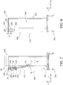
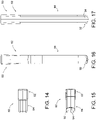
- FIGs 11-18 illustrate a retention clip 60 according to an embodiment of the present disclosure.
- the retention clip 60 includes an engagement head 62 for attachment to the sample rack 200 and a curved tail 64 that extends from the engagement head 62.
- the engagement head 62 includes a bridge 66 that extends along a vertical direction V and has a generally linear profile.
- the curved tail 64 extends downwardly from a lower end of the bridge 66.
- the engagement head 62 further includes an upper engagement member 70 and a lower engagement member 80 that is spaced apart from the upper engagement member 70.
- the upper engagement member 70 and the lower engagement member 80 are adapted to attach the engagement head 62 to the sample rack 200.
- the engagement head 62 includes an outer surface 65.
- the bridge 66 includes a contact surface 68 that extends from the upper engagement member 70 to the lower engagement member 80.
- the upper engagement member 70 extends from the bridge 66 along a transverse direction T that is perpendicular to the vertical direction V. As illustrated, the upper engagement member 70 includes a first flange 72 and a first protrusion 74 that extends from the first flange 72 along the vertical direction V toward the lower engagement member 80.
- the protrusion 74 defines an engagement surface 76 that may face, and in some instances is substantially parallel to, the contact surface 68 of the bridge 66.
- the upper engagement member 70 further defines an upper-most surface 71. In accordance with at least one embodiment, no other portion of the retention clip 60 extends above the upper-most surface 71 along the vertical direction V.
- the lower engagement member 80 extends from the bridge 66 along the transverse direction T and is also spaced from the upper engagement member 70. In this manner, the lower engagement member 80 can at least partially face the upper engagement member 70.
- the lower engagement member 80 includes a second flange 82 and a second protrusion 84 that extends from the second flange 82 along the vertical direction V toward the upper engagement member 70.
- the second protrusion 84 defines an engagement surface 86 that may face, and in some instances is substantially parallel to, the contact surface 68 of the bridge 66.
- the lower engagement member may optionally include an inclined surface 88 that extends between the second flange and an upper end of the curved tail 64. The inclined surface 88 is angularly offset with respect to the contact surface 68 of the bridge 66.
- the engagement head 62 may optionally include a plurality of notches. As illustrated, the engagement head 62 includes a first notch 90a where the upper engagement member 70 and the bridge 66 intersect, and a second notch 90b where the lower engagement member 80 and bridge 66 intersect. A third notch 90c is located at the corner of the first flange 72 and first protrusion 74 and a fourth notch 90d may be located at the corner of the second flange 82 and second protrusion 84. Each of the notches 90a-90d may be configured to minimize stress concentrations in the engagement head 62 where various surfaces intersect at relatively sharp angles (such as about 90 degrees or less).
- the notches 90a-90d may help improve durability of the retention clips 60 when subjected to stresses that accompany attaching and detaching the engagement head 62 to and from the receiver element 250 of the sample rack 20, respectively.
- the bridge 66, the upper engagement member 70, and the lower engagement member 80 flex in order to attach to the recess surfaces 254 and grooves 258, 260 of the receiver element 250.
- Repeated use, and thus repeated flexing may induce cracks at sharp corners.
- the notches may be used to reduce stress concentrations at sharp corners during repeated flexing described above.
- the curved tail 64 is curved in a direction 69a opposite to a direction 69b that the upper engagement member 70 and the lower engagement member 80 extend. As shown, the curved tail 64 curves as it extends from a lower engagement member 80 to its terminal end 92.
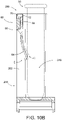
- the tail terminal end 92 includes a curved contact surface 94 for contact with the sample collection unit 50, as best shown in Figures 10A and 10B .
- the terminal end 92 is offset with respect to plane P that extends through the bridge 66 along the vertical direction V.
- the curved tail 64 is designed to flex in response to sample collection unit 50 being inserted into the receptacle 240 of the sample rack 200. More specifically, application of a force by inserting the sample collection unit 50 into the receptacle 240 causes to the curved tail 64 to deflect from a curved configuration C (shown in dashed lines in Figures 10A and 10B ) into a linear configuration E (as best shown in solid lines in Figures 10A and 10B ). In the linear configuration, the curved tail 64 is straightened so that the tail 64 substantially parallel to vertical axis 2 that is aligned with the vertical direction V.
- the curved tail 64 is deflectable within a footprint of the sample rack 200 defined by the base and sides of the sample rack.
- the flexural rigidity of the curved tail 64 is designed to maintain contact with sample collection unit 50 during insertion into the receptacle and through subsequent use in the analysis system 1.
- the retention clip 60 has several advantageous features.
- the retention clip 60 as illustrated is suitable for holding in place a wide range of sample collection units and types.
- the retention clip 60 is suitable for use with typical sample collection units that have a semi-spherical bottom.
- the spherical bottom rides along the curved tail 64 and also causes the curved tail to deflect until the terminal end begins to ride along the sides of the sample collection tube. This interaction improves smoothness of inserting (or removing) sample collection units.
- skirted bottom which is typically flat, does not get caught on any structure protruding from the curved tail.
- the skirted bottom of the sample collection unit abuts and then rides along the curved tail 64. Once the terminal end clears the curved bottom, the risk of sample collection unit catching in the receptacle before full insertion is complete is minimized.
- the retention clip 60 has a low profile engagement head 62 that is designed to fit within a recessed region of a sample rack 200.
- the low-profile engagement head does not project outwardly with respect to the sample rack. This, in turn, minimizes instances where the sample rack catches on the structure of the test device when the sample rack is moving into the testing region of those devices.
- the invention as described in the present disclosure is capable of exploitation in industry in accordance with how it can be made and/or used.
Landscapes
- Chemical & Material Sciences (AREA)
- Health & Medical Sciences (AREA)
- Chemical Kinetics & Catalysis (AREA)
- Clinical Laboratory Science (AREA)
- General Health & Medical Sciences (AREA)
- Analytical Chemistry (AREA)
- Biochemistry (AREA)
- Physics & Mathematics (AREA)
- General Physics & Mathematics (AREA)
- Immunology (AREA)
- Pathology (AREA)
- Life Sciences & Earth Sciences (AREA)
- Hematology (AREA)
- Automatic Analysis And Handling Materials Therefor (AREA)
Claims (4)
- Halteklammer (60) zum Anbringen an einem Probengestell (200), das dazu ausgeführt ist, eine oder mehrere Probensammeleinheiten (50) zu halten, wobei die Halteklammer (60) Folgendes umfasst:einen Eingriffskopf (62) zum Anbringen an dem Probengestell (200), wobei der Eingriffskopf (62) Folgendes hat:a) ein oberes Eingriffsglied (70), das sich von einer Brücke (66) entlang einer Querrichtung (T) erstreckt, die senkrecht zu der vertikalen Richtung (V) verläuft, wobei das obere Eingriffsglied (70) einen ersten Flansch (72) und einen ersten Vorsprung (74) aufweist, der sich von dem ersten Flansch (72) entlang der vertikalen Richtung (V) erstreckt, wobeib) sich die Brücke (66) entlang einer vertikalen Richtung (V) erstreckt, und
einen gekrümmten Schwanz (64), der sich von dem Eingriffskopf (62) erstreckt,dadurch gekennzeichnet, dass der Eingriffskopf (62) ferner Folgendes umfasst:
c) ein unteres Eingriffsglied (80), das sich von der Brücke (66) entlang der Querrichtung (T) erstreckt und von dem oberen Eingriffsglied (70) beabstandet ist, um dem oberen Eingriffsglied (70) gegenüberzuliegen, wobei das obere Eingriffsglied (70) und das untere Eingriffsglied (80) den Eingriffskopf (62) an dem Probengestell (200) anbringen, wobei sich der erste Vorsprung (74) des oberen Eingriffsglieds (70) zu dem unteren Eingriffsglied (80) hin erstreckt und das untere Eingriffsglied (80) einen zweiten Flansch (82) und einen zweiten Vorsprung (84) aufweist, der sich von dem zweiten Flansch (82) entlang der vertikalen Richtung (V) zu dem oberen Eingriffsglied (70) hin erstreckt,wobei sich der gekrümmte Schwanz (64) von dem unteren Eingriffsglied (80) der Brücke (66) nach unten zu einem endständigen Ende (92) des gekrümmten Schwanzes (64) erstreckt und wobei der gekrümmte Schwanz (64) in einer Richtung (69a) gekrümmt ist, die einer Richtung (69b) entgegengesetzt ist, in der sich das obere Eingriffsglied (70) und das untere Erfindungsglied (80) erstrecken, undwobei der gekrümmte Schwanz (64) das endständige Ende (92) definiert, das eine gekrümmte Kontaktfläche (94) aufweist, wobei das endständige Ende (92) bezüglich einer vertikalen Ebene (P), die sich durch die Brücke (66) entlang der vertikalen Richtung (V) erstreckt, versetzt ist. - Halteklammer (60) nach Anspruch 1, wobei die Brücke (66) eine Kontaktfläche (68) aufweist, die sich von dem oberen Eingriffsglied (70) zu dem unteren Eingriffsglied (80) erstreckt, wobei ein Abschnitt des oberen Eingriffsglieds und ein Abschnitt des unteren Eingriffsglieds (80) im Wesentlichen parallel zu der Kontaktfläche (68) verlaufen.
- Halteklammer nach Anspruch 1, wobei das untere Eingriffsglied (80) eine geneigte Fläche aufweist, die sich zwischen dem zweiten Flansch (82) und dem zweiten Vorsprung (84) erstreckt, wobei die geneigte Fläche bezüglich der Kontaktfläche (68) winkelmäßig versetzt ist.
- Halteklammer nach Anspruch 1 oder 2, wobei das obere Eingriffsglied (70) eine oberste Fläche (71) definiert, wobei sich kein anderer Abschnitt der Halteklammer (60) über die oberste Fläche (71) entlang der vertikalen Richtung (V) erstreckt.
Applications Claiming Priority (2)
| Application Number | Priority Date | Filing Date | Title |
|---|---|---|---|
| US201762504113P | 2017-05-10 | 2017-05-10 | |
| PCT/US2018/031549 WO2018208748A1 (en) | 2017-05-10 | 2018-05-08 | Retention clip and sample rack for a sample analysis system |
Publications (3)
| Publication Number | Publication Date |
|---|---|
| EP3621737A1 EP3621737A1 (de) | 2020-03-18 |
| EP3621737A4 EP3621737A4 (de) | 2020-04-15 |
| EP3621737B1 true EP3621737B1 (de) | 2022-10-05 |
Family
ID=64104979
Family Applications (1)
| Application Number | Title | Priority Date | Filing Date |
|---|---|---|---|
| EP18799382.9A Active EP3621737B1 (de) | 2017-05-10 | 2018-05-08 | Halteklammer und probenrack für ein probenanalysesystem |
Country Status (3)
| Country | Link |
|---|---|
| US (1) | US11745186B2 (de) |
| EP (1) | EP3621737B1 (de) |
| WO (1) | WO2018208748A1 (de) |
Families Citing this family (3)
| Publication number | Priority date | Publication date | Assignee | Title |
|---|---|---|---|---|
| USD938612S1 (en) * | 2017-06-16 | 2021-12-14 | Beckman Coulter, Inc. | Sample rack |
| FR3083785B1 (fr) * | 2018-07-10 | 2020-06-19 | Technoflex | Dispositif de maintien pour recipients comportant un tuyau de remplissage et utilisation dudit dispositif |
| CN121300643A (zh) * | 2024-07-08 | 2026-01-09 | 瑞马科宝股份有限公司 | 捕获对象弯曲机制 |
Family Cites Families (11)
| Publication number | Priority date | Publication date | Assignee | Title |
|---|---|---|---|---|
| US2741913A (en) * | 1954-07-20 | 1956-04-17 | Dovas Nicholas | Blood sedimentation rack |
| US5137693A (en) | 1990-07-30 | 1992-08-11 | Miles Inc. | Spring biased test tube holder |
| DE69308493T2 (de) * | 1992-06-29 | 1997-10-23 | Dade Int Inc | Träger für proberöhrchen |
| SE9500777D0 (sv) * | 1995-03-03 | 1995-03-03 | Pharmacia Ab | Provrörshållarinsats |
| US6156257A (en) | 1995-12-28 | 2000-12-05 | Toyoda Gosei Co., Ltd | Reactive injection molding process for manufacturing a two-colored molded polyurethane products |
| US6123205A (en) * | 1997-11-26 | 2000-09-26 | Bayer Corporation | Sample tube rack |
| JP4332513B2 (ja) * | 2005-03-31 | 2009-09-16 | 株式会社アイディエス | 試験管ホルダー |
| KR101184455B1 (ko) * | 2006-12-22 | 2012-09-20 | 삼성전자주식회사 | 용기홀더 및 이를 포함하는 식기세척기 |
| US20090145866A1 (en) | 2007-12-10 | 2009-06-11 | Michael Harmik Panosian | Wall organizing system |
| GB2481590B (en) * | 2010-06-28 | 2015-11-11 | Jui-Chien Kao | Tool rack |
| EP3498435B1 (de) | 2010-10-29 | 2020-07-22 | Thermo Fisher Scientific Oy | Greifer |
-
2018
- 2018-05-08 US US16/609,545 patent/US11745186B2/en active Active
- 2018-05-08 WO PCT/US2018/031549 patent/WO2018208748A1/en not_active Ceased
- 2018-05-08 EP EP18799382.9A patent/EP3621737B1/de active Active
Also Published As
| Publication number | Publication date |
|---|---|
| WO2018208748A1 (en) | 2018-11-15 |
| EP3621737A4 (de) | 2020-04-15 |
| EP3621737A1 (de) | 2020-03-18 |
| US20200114364A1 (en) | 2020-04-16 |
| US11745186B2 (en) | 2023-09-05 |
Similar Documents
| Publication | Publication Date | Title |
|---|---|---|
| CA2119816C (en) | Test strip analysis system | |
| US10670499B2 (en) | Station, used for test apparatus, having integrated reaction and detection means | |
| EP3621737B1 (de) | Halteklammer und probenrack für ein probenanalysesystem | |
| US8802037B2 (en) | Sample well strip | |
| ES2630213T3 (es) | Sistema y método para el procesamiento automatizado de fluidos, método para determinar la coincidencia de objetos | |
| JP2010078483A (ja) | 試験管ホルダー | |
| CA2547109A1 (en) | Disposable reaction vessel with integrated optical elements | |
| EP2397859B1 (de) | Optische Überwachung des Mischens und Trennens | |
| US11733256B2 (en) | Sample rack handler and rotation assembly for a sample analysis system | |
| CN116868061A (zh) | 将诊断实验室系统的部件进行对准的装置和方法 | |
| US11644475B2 (en) | Sample rack for sample analysis system | |
| US7224448B2 (en) | Apparatus and methods for evaluating an optical property of a liquid sample | |
| US20240299946A1 (en) | Ready to use analyzer control product for cua urinalysis instruments | |
| US20220299431A1 (en) | Assay membrane test region localization | |
| CN213337653U (zh) | 一种医疗设备用检测装置及医疗设备 | |
| US20130303029A1 (en) | Electrical connector and electrical connector having a strip | |
| US11040348B2 (en) | Biological sample analysis kit and sample collection unit with a cap having an access opening | |
| CN215678416U (zh) | 一种兼容荧光酶标仪的多通道试纸条测定板 | |
| US7579194B2 (en) | Apparatus and method for investigating chemical entities | |
| WO2026033936A1 (ja) | 検体ラック | |
| JPH04134070U (ja) | 自動分析装置の検体ラツク | |
| HK1008441B (en) | Test-strip analysis system |
Legal Events
| Date | Code | Title | Description |
|---|---|---|---|
| STAA | Information on the status of an ep patent application or granted ep patent |
Free format text: STATUS: THE INTERNATIONAL PUBLICATION HAS BEEN MADE |
|
| PUAI | Public reference made under article 153(3) epc to a published international application that has entered the european phase |
Free format text: ORIGINAL CODE: 0009012 |
|
| STAA | Information on the status of an ep patent application or granted ep patent |
Free format text: STATUS: REQUEST FOR EXAMINATION WAS MADE |
|
| 17P | Request for examination filed |
Effective date: 20191202 |
|
| AK | Designated contracting states |
Kind code of ref document: A1 Designated state(s): AL AT BE BG CH CY CZ DE DK EE ES FI FR GB GR HR HU IE IS IT LI LT LU LV MC MK MT NL NO PL PT RO RS SE SI SK SM TR |
|
| AX | Request for extension of the european patent |
Extension state: BA ME |
|
| A4 | Supplementary search report drawn up and despatched |
Effective date: 20200316 |
|
| RIC1 | Information provided on ipc code assigned before grant |
Ipc: G01N 35/02 20060101ALN20200310BHEP Ipc: A47F 7/00 20060101ALI20200310BHEP Ipc: B01L 9/06 20060101AFI20200310BHEP Ipc: A47F 5/08 20060101ALN20200310BHEP Ipc: B01L 3/00 20060101ALN20200310BHEP |
|
| RIN1 | Information on inventor provided before grant (corrected) |
Inventor name: HOJER, GYULA Inventor name: DUNBAR, ANDREW Inventor name: LASZKA, NORBERT Inventor name: CHEN, MICHAEL Inventor name: PERRY, WILLIAM Inventor name: GEEHAN, STEVEN |
|
| DAV | Request for validation of the european patent (deleted) | ||
| DAX | Request for extension of the european patent (deleted) | ||
| STAA | Information on the status of an ep patent application or granted ep patent |
Free format text: STATUS: EXAMINATION IS IN PROGRESS |
|
| 17Q | First examination report despatched |
Effective date: 20201116 |
|
| REG | Reference to a national code |
Ref country code: DE Ref legal event code: R079 Ref document number: 602018041463 Country of ref document: DE Free format text: PREVIOUS MAIN CLASS: B01L0003140000 Ipc: B01L0009060000 |
|
| RIC1 | Information provided on ipc code assigned before grant |
Ipc: B01L 3/00 20060101ALN20220201BHEP Ipc: G01N 35/04 20060101ALI20220201BHEP Ipc: G01N 35/02 20060101ALI20220201BHEP Ipc: A47F 7/00 20060101ALI20220201BHEP Ipc: B01L 9/06 20060101AFI20220201BHEP |
|
| RIC1 | Information provided on ipc code assigned before grant |
Ipc: B01L 3/00 20060101ALN20220307BHEP Ipc: G01N 35/04 20060101ALI20220307BHEP Ipc: G01N 35/02 20060101ALI20220307BHEP Ipc: A47F 7/00 20060101ALI20220307BHEP Ipc: B01L 9/06 20060101AFI20220307BHEP |
|
| GRAP | Despatch of communication of intention to grant a patent |
Free format text: ORIGINAL CODE: EPIDOSNIGR1 |
|
| STAA | Information on the status of an ep patent application or granted ep patent |
Free format text: STATUS: GRANT OF PATENT IS INTENDED |
|
| INTG | Intention to grant announced |
Effective date: 20220419 |
|
| GRAS | Grant fee paid |
Free format text: ORIGINAL CODE: EPIDOSNIGR3 |
|
| GRAA | (expected) grant |
Free format text: ORIGINAL CODE: 0009210 |
|
| STAA | Information on the status of an ep patent application or granted ep patent |
Free format text: STATUS: THE PATENT HAS BEEN GRANTED |
|
| AK | Designated contracting states |
Kind code of ref document: B1 Designated state(s): AL AT BE BG CH CY CZ DE DK EE ES FI FR GB GR HR HU IE IS IT LI LT LU LV MC MK MT NL NO PL PT RO RS SE SI SK SM TR |
|
| REG | Reference to a national code |
Ref country code: GB Ref legal event code: FG4D |
|
| REG | Reference to a national code |
Ref country code: CH Ref legal event code: EP |
|
| REG | Reference to a national code |
Ref country code: AT Ref legal event code: REF Ref document number: 1522405 Country of ref document: AT Kind code of ref document: T Effective date: 20221015 |
|
| REG | Reference to a national code |
Ref country code: IE Ref legal event code: FG4D |
|
| REG | Reference to a national code |
Ref country code: DE Ref legal event code: R096 Ref document number: 602018041463 Country of ref document: DE |
|
| REG | Reference to a national code |
Ref country code: LT Ref legal event code: MG9D |
|
| REG | Reference to a national code |
Ref country code: NL Ref legal event code: MP Effective date: 20221005 |
|
| REG | Reference to a national code |
Ref country code: AT Ref legal event code: MK05 Ref document number: 1522405 Country of ref document: AT Kind code of ref document: T Effective date: 20221005 |
|
| PG25 | Lapsed in a contracting state [announced via postgrant information from national office to epo] |
Ref country code: NL Free format text: LAPSE BECAUSE OF FAILURE TO SUBMIT A TRANSLATION OF THE DESCRIPTION OR TO PAY THE FEE WITHIN THE PRESCRIBED TIME-LIMIT Effective date: 20221005 |
|
| PG25 | Lapsed in a contracting state [announced via postgrant information from national office to epo] |
Ref country code: SE Free format text: LAPSE BECAUSE OF FAILURE TO SUBMIT A TRANSLATION OF THE DESCRIPTION OR TO PAY THE FEE WITHIN THE PRESCRIBED TIME-LIMIT Effective date: 20221005 Ref country code: PT Free format text: LAPSE BECAUSE OF FAILURE TO SUBMIT A TRANSLATION OF THE DESCRIPTION OR TO PAY THE FEE WITHIN THE PRESCRIBED TIME-LIMIT Effective date: 20230206 Ref country code: NO Free format text: LAPSE BECAUSE OF FAILURE TO SUBMIT A TRANSLATION OF THE DESCRIPTION OR TO PAY THE FEE WITHIN THE PRESCRIBED TIME-LIMIT Effective date: 20230105 Ref country code: LT Free format text: LAPSE BECAUSE OF FAILURE TO SUBMIT A TRANSLATION OF THE DESCRIPTION OR TO PAY THE FEE WITHIN THE PRESCRIBED TIME-LIMIT Effective date: 20221005 Ref country code: FI Free format text: LAPSE BECAUSE OF FAILURE TO SUBMIT A TRANSLATION OF THE DESCRIPTION OR TO PAY THE FEE WITHIN THE PRESCRIBED TIME-LIMIT Effective date: 20221005 Ref country code: ES Free format text: LAPSE BECAUSE OF FAILURE TO SUBMIT A TRANSLATION OF THE DESCRIPTION OR TO PAY THE FEE WITHIN THE PRESCRIBED TIME-LIMIT Effective date: 20221005 Ref country code: AT Free format text: LAPSE BECAUSE OF FAILURE TO SUBMIT A TRANSLATION OF THE DESCRIPTION OR TO PAY THE FEE WITHIN THE PRESCRIBED TIME-LIMIT Effective date: 20221005 |
|
| PG25 | Lapsed in a contracting state [announced via postgrant information from national office to epo] |
Ref country code: RS Free format text: LAPSE BECAUSE OF FAILURE TO SUBMIT A TRANSLATION OF THE DESCRIPTION OR TO PAY THE FEE WITHIN THE PRESCRIBED TIME-LIMIT Effective date: 20221005 Ref country code: PL Free format text: LAPSE BECAUSE OF FAILURE TO SUBMIT A TRANSLATION OF THE DESCRIPTION OR TO PAY THE FEE WITHIN THE PRESCRIBED TIME-LIMIT Effective date: 20221005 Ref country code: LV Free format text: LAPSE BECAUSE OF FAILURE TO SUBMIT A TRANSLATION OF THE DESCRIPTION OR TO PAY THE FEE WITHIN THE PRESCRIBED TIME-LIMIT Effective date: 20221005 Ref country code: IS Free format text: LAPSE BECAUSE OF FAILURE TO SUBMIT A TRANSLATION OF THE DESCRIPTION OR TO PAY THE FEE WITHIN THE PRESCRIBED TIME-LIMIT Effective date: 20230205 Ref country code: HR Free format text: LAPSE BECAUSE OF FAILURE TO SUBMIT A TRANSLATION OF THE DESCRIPTION OR TO PAY THE FEE WITHIN THE PRESCRIBED TIME-LIMIT Effective date: 20221005 Ref country code: GR Free format text: LAPSE BECAUSE OF FAILURE TO SUBMIT A TRANSLATION OF THE DESCRIPTION OR TO PAY THE FEE WITHIN THE PRESCRIBED TIME-LIMIT Effective date: 20230106 |
|
| REG | Reference to a national code |
Ref country code: DE Ref legal event code: R097 Ref document number: 602018041463 Country of ref document: DE |
|
| PG25 | Lapsed in a contracting state [announced via postgrant information from national office to epo] |
Ref country code: SM Free format text: LAPSE BECAUSE OF FAILURE TO SUBMIT A TRANSLATION OF THE DESCRIPTION OR TO PAY THE FEE WITHIN THE PRESCRIBED TIME-LIMIT Effective date: 20221005 Ref country code: RO Free format text: LAPSE BECAUSE OF FAILURE TO SUBMIT A TRANSLATION OF THE DESCRIPTION OR TO PAY THE FEE WITHIN THE PRESCRIBED TIME-LIMIT Effective date: 20221005 Ref country code: EE Free format text: LAPSE BECAUSE OF FAILURE TO SUBMIT A TRANSLATION OF THE DESCRIPTION OR TO PAY THE FEE WITHIN THE PRESCRIBED TIME-LIMIT Effective date: 20221005 Ref country code: DK Free format text: LAPSE BECAUSE OF FAILURE TO SUBMIT A TRANSLATION OF THE DESCRIPTION OR TO PAY THE FEE WITHIN THE PRESCRIBED TIME-LIMIT Effective date: 20221005 Ref country code: CZ Free format text: LAPSE BECAUSE OF FAILURE TO SUBMIT A TRANSLATION OF THE DESCRIPTION OR TO PAY THE FEE WITHIN THE PRESCRIBED TIME-LIMIT Effective date: 20221005 |
|
| PLBE | No opposition filed within time limit |
Free format text: ORIGINAL CODE: 0009261 |
|
| STAA | Information on the status of an ep patent application or granted ep patent |
Free format text: STATUS: NO OPPOSITION FILED WITHIN TIME LIMIT |
|
| PG25 | Lapsed in a contracting state [announced via postgrant information from national office to epo] |
Ref country code: SK Free format text: LAPSE BECAUSE OF FAILURE TO SUBMIT A TRANSLATION OF THE DESCRIPTION OR TO PAY THE FEE WITHIN THE PRESCRIBED TIME-LIMIT Effective date: 20221005 Ref country code: AL Free format text: LAPSE BECAUSE OF FAILURE TO SUBMIT A TRANSLATION OF THE DESCRIPTION OR TO PAY THE FEE WITHIN THE PRESCRIBED TIME-LIMIT Effective date: 20221005 |
|
| 26N | No opposition filed |
Effective date: 20230706 |
|
| PG25 | Lapsed in a contracting state [announced via postgrant information from national office to epo] |
Ref country code: SI Free format text: LAPSE BECAUSE OF FAILURE TO SUBMIT A TRANSLATION OF THE DESCRIPTION OR TO PAY THE FEE WITHIN THE PRESCRIBED TIME-LIMIT Effective date: 20221005 |
|
| REG | Reference to a national code |
Ref country code: CH Ref legal event code: PL |
|
| PG25 | Lapsed in a contracting state [announced via postgrant information from national office to epo] |
Ref country code: MC Free format text: LAPSE BECAUSE OF FAILURE TO SUBMIT A TRANSLATION OF THE DESCRIPTION OR TO PAY THE FEE WITHIN THE PRESCRIBED TIME-LIMIT Effective date: 20221005 |
|
| REG | Reference to a national code |
Ref country code: BE Ref legal event code: MM Effective date: 20230531 |
|
| PG25 | Lapsed in a contracting state [announced via postgrant information from national office to epo] |
Ref country code: MC Free format text: LAPSE BECAUSE OF FAILURE TO SUBMIT A TRANSLATION OF THE DESCRIPTION OR TO PAY THE FEE WITHIN THE PRESCRIBED TIME-LIMIT Effective date: 20221005 Ref country code: LU Free format text: LAPSE BECAUSE OF NON-PAYMENT OF DUE FEES Effective date: 20230508 Ref country code: LI Free format text: LAPSE BECAUSE OF NON-PAYMENT OF DUE FEES Effective date: 20230531 Ref country code: CH Free format text: LAPSE BECAUSE OF NON-PAYMENT OF DUE FEES Effective date: 20230531 |
|
| REG | Reference to a national code |
Ref country code: IE Ref legal event code: MM4A |
|
| PG25 | Lapsed in a contracting state [announced via postgrant information from national office to epo] |
Ref country code: IE Free format text: LAPSE BECAUSE OF NON-PAYMENT OF DUE FEES Effective date: 20230508 |
|
| PG25 | Lapsed in a contracting state [announced via postgrant information from national office to epo] |
Ref country code: IE Free format text: LAPSE BECAUSE OF NON-PAYMENT OF DUE FEES Effective date: 20230508 |
|
| PG25 | Lapsed in a contracting state [announced via postgrant information from national office to epo] |
Ref country code: IT Free format text: LAPSE BECAUSE OF FAILURE TO SUBMIT A TRANSLATION OF THE DESCRIPTION OR TO PAY THE FEE WITHIN THE PRESCRIBED TIME-LIMIT Effective date: 20221005 Ref country code: FR Free format text: LAPSE BECAUSE OF NON-PAYMENT OF DUE FEES Effective date: 20230531 Ref country code: BE Free format text: LAPSE BECAUSE OF NON-PAYMENT OF DUE FEES Effective date: 20230531 |
|
| PG25 | Lapsed in a contracting state [announced via postgrant information from national office to epo] |
Ref country code: BG Free format text: LAPSE BECAUSE OF FAILURE TO SUBMIT A TRANSLATION OF THE DESCRIPTION OR TO PAY THE FEE WITHIN THE PRESCRIBED TIME-LIMIT Effective date: 20221005 |
|
| PG25 | Lapsed in a contracting state [announced via postgrant information from national office to epo] |
Ref country code: BG Free format text: LAPSE BECAUSE OF FAILURE TO SUBMIT A TRANSLATION OF THE DESCRIPTION OR TO PAY THE FEE WITHIN THE PRESCRIBED TIME-LIMIT Effective date: 20221005 |
|
| PGFP | Annual fee paid to national office [announced via postgrant information from national office to epo] |
Ref country code: GB Payment date: 20250610 Year of fee payment: 8 |
|
| PG25 | Lapsed in a contracting state [announced via postgrant information from national office to epo] |
Ref country code: CY Free format text: LAPSE BECAUSE OF FAILURE TO SUBMIT A TRANSLATION OF THE DESCRIPTION OR TO PAY THE FEE WITHIN THE PRESCRIBED TIME-LIMIT; INVALID AB INITIO Effective date: 20180508 |
|
| REG | Reference to a national code |
Ref country code: DE Ref legal event code: R082 Ref document number: 602018041463 Country of ref document: DE |
|
| PG25 | Lapsed in a contracting state [announced via postgrant information from national office to epo] |
Ref country code: HU Free format text: LAPSE BECAUSE OF FAILURE TO SUBMIT A TRANSLATION OF THE DESCRIPTION OR TO PAY THE FEE WITHIN THE PRESCRIBED TIME-LIMIT; INVALID AB INITIO Effective date: 20180508 |
|
| PGFP | Annual fee paid to national office [announced via postgrant information from national office to epo] |
Ref country code: DE Payment date: 20250718 Year of fee payment: 8 |
|
| PG25 | Lapsed in a contracting state [announced via postgrant information from national office to epo] |
Ref country code: TR Free format text: LAPSE BECAUSE OF FAILURE TO SUBMIT A TRANSLATION OF THE DESCRIPTION OR TO PAY THE FEE WITHIN THE PRESCRIBED TIME-LIMIT Effective date: 20221005 |