EP3621748B1 - Düse und applikatorsystem damit - Google Patents
Düse und applikatorsystem damit Download PDFInfo
- Publication number
- EP3621748B1 EP3621748B1 EP18727553.2A EP18727553A EP3621748B1 EP 3621748 B1 EP3621748 B1 EP 3621748B1 EP 18727553 A EP18727553 A EP 18727553A EP 3621748 B1 EP3621748 B1 EP 3621748B1
- Authority
- EP
- European Patent Office
- Prior art keywords
- nozzle
- baffle plate
- nozzle assembly
- cutout
- along
- Prior art date
- Legal status (The legal status is an assumption and is not a legal conclusion. Google has not performed a legal analysis and makes no representation as to the accuracy of the status listed.)
- Active
Links
Images


Classifications
-
- B—PERFORMING OPERATIONS; TRANSPORTING
- B05—SPRAYING OR ATOMISING IN GENERAL; APPLYING FLUENT MATERIALS TO SURFACES, IN GENERAL
- B05B—SPRAYING APPARATUS; ATOMISING APPARATUS; NOZZLES
- B05B1/00—Nozzles, spray heads or other outlets, with or without auxiliary devices such as valves, heating means
- B05B1/30—Nozzles, spray heads or other outlets, with or without auxiliary devices such as valves, heating means designed to control volume of flow, e.g. with adjustable passages
-
- B—PERFORMING OPERATIONS; TRANSPORTING
- B05—SPRAYING OR ATOMISING IN GENERAL; APPLYING FLUENT MATERIALS TO SURFACES, IN GENERAL
- B05B—SPRAYING APPARATUS; ATOMISING APPARATUS; NOZZLES
- B05B1/00—Nozzles, spray heads or other outlets, with or without auxiliary devices such as valves, heating means
- B05B1/02—Nozzles, spray heads or other outlets, with or without auxiliary devices such as valves, heating means designed to produce a jet, spray, or other discharge of particular shape or nature, e.g. in single drops, or having an outlet of particular shape
- B05B1/04—Nozzles, spray heads or other outlets, with or without auxiliary devices such as valves, heating means designed to produce a jet, spray, or other discharge of particular shape or nature, e.g. in single drops, or having an outlet of particular shape in flat form, e.g. fan-like, sheet-like
- B05B1/044—Slits, e.g. narrow openings defined by two straight and parallel lips; Elongated outlets for producing very wide discharges, e.g. fluid curtains
-
- B—PERFORMING OPERATIONS; TRANSPORTING
- B05—SPRAYING OR ATOMISING IN GENERAL; APPLYING FLUENT MATERIALS TO SURFACES, IN GENERAL
- B05B—SPRAYING APPARATUS; ATOMISING APPARATUS; NOZZLES
- B05B1/00—Nozzles, spray heads or other outlets, with or without auxiliary devices such as valves, heating means
- B05B1/30—Nozzles, spray heads or other outlets, with or without auxiliary devices such as valves, heating means designed to control volume of flow, e.g. with adjustable passages
- B05B1/3013—Lift valves
- B05B1/302—Lift valves with a ball shaped valve member
-
- B—PERFORMING OPERATIONS; TRANSPORTING
- B05—SPRAYING OR ATOMISING IN GENERAL; APPLYING FLUENT MATERIALS TO SURFACES, IN GENERAL
- B05B—SPRAYING APPARATUS; ATOMISING APPARATUS; NOZZLES
- B05B15/00—Details of spraying plant or spraying apparatus not otherwise provided for; Accessories
- B05B15/60—Arrangements for mounting, supporting or holding spraying apparatus
- B05B15/65—Mounting arrangements for fluid connection of the spraying apparatus or its outlets to flow conduits
- B05B15/658—Mounting arrangements for fluid connection of the spraying apparatus or its outlets to flow conduits the spraying apparatus or its outlet axis being perpendicular to the flow conduit
-
- B—PERFORMING OPERATIONS; TRANSPORTING
- B05—SPRAYING OR ATOMISING IN GENERAL; APPLYING FLUENT MATERIALS TO SURFACES, IN GENERAL
- B05B—SPRAYING APPARATUS; ATOMISING APPARATUS; NOZZLES
- B05B9/00—Spraying apparatus for discharge of liquids or other fluent material, without essentially mixing with gas or vapour
- B05B9/03—Spraying apparatus for discharge of liquids or other fluent material, without essentially mixing with gas or vapour characterised by means for supplying liquid or other fluent material
- B05B9/04—Spraying apparatus for discharge of liquids or other fluent material, without essentially mixing with gas or vapour characterised by means for supplying liquid or other fluent material with pressurised or compressible container; with pump
- B05B9/0403—Spraying apparatus for discharge of liquids or other fluent material, without essentially mixing with gas or vapour characterised by means for supplying liquid or other fluent material with pressurised or compressible container; with pump with pumps for liquids or other fluent material
- B05B9/0413—Spraying apparatus for discharge of liquids or other fluent material, without essentially mixing with gas or vapour characterised by means for supplying liquid or other fluent material with pressurised or compressible container; with pump with pumps for liquids or other fluent material with reciprocating pumps, e.g. membrane pump, piston pump, bellow pump
-
- B—PERFORMING OPERATIONS; TRANSPORTING
- B05—SPRAYING OR ATOMISING IN GENERAL; APPLYING FLUENT MATERIALS TO SURFACES, IN GENERAL
- B05C—APPARATUS FOR APPLYING FLUENT MATERIALS TO SURFACES, IN GENERAL
- B05C5/00—Apparatus in which liquid or other fluent material is projected, poured or allowed to flow on to the surface of the work
- B05C5/001—Apparatus in which liquid or other fluent material is projected, poured or allowed to flow on to the surface of the work incorporating means for heating or cooling the liquid or other fluent material
-
- B—PERFORMING OPERATIONS; TRANSPORTING
- B05—SPRAYING OR ATOMISING IN GENERAL; APPLYING FLUENT MATERIALS TO SURFACES, IN GENERAL
- B05C—APPARATUS FOR APPLYING FLUENT MATERIALS TO SURFACES, IN GENERAL
- B05C5/00—Apparatus in which liquid or other fluent material is projected, poured or allowed to flow on to the surface of the work
- B05C5/02—Apparatus in which liquid or other fluent material is projected, poured or allowed to flow on to the surface of the work the liquid or other fluent material being discharged through an outlet orifice by pressure, e.g. from an outlet device in contact or almost in contact, with the work
- B05C5/0254—Coating heads with slot-shaped outlet
- B05C5/0258—Coating heads with slot-shaped outlet flow controlled, e.g. by a valve
-
- B—PERFORMING OPERATIONS; TRANSPORTING
- B05—SPRAYING OR ATOMISING IN GENERAL; APPLYING FLUENT MATERIALS TO SURFACES, IN GENERAL
- B05B—SPRAYING APPARATUS; ATOMISING APPARATUS; NOZZLES
- B05B1/00—Nozzles, spray heads or other outlets, with or without auxiliary devices such as valves, heating means
- B05B1/36—Outlets for discharging by overflow
-
- B—PERFORMING OPERATIONS; TRANSPORTING
- B05—SPRAYING OR ATOMISING IN GENERAL; APPLYING FLUENT MATERIALS TO SURFACES, IN GENERAL
- B05B—SPRAYING APPARATUS; ATOMISING APPARATUS; NOZZLES
- B05B9/00—Spraying apparatus for discharge of liquids or other fluent material, without essentially mixing with gas or vapour
- B05B9/002—Spraying apparatus for discharge of liquids or other fluent material, without essentially mixing with gas or vapour incorporating means for heating or cooling, e.g. the material to be sprayed
-
- B—PERFORMING OPERATIONS; TRANSPORTING
- B05—SPRAYING OR ATOMISING IN GENERAL; APPLYING FLUENT MATERIALS TO SURFACES, IN GENERAL
- B05B—SPRAYING APPARATUS; ATOMISING APPARATUS; NOZZLES
- B05B9/00—Spraying apparatus for discharge of liquids or other fluent material, without essentially mixing with gas or vapour
- B05B9/03—Spraying apparatus for discharge of liquids or other fluent material, without essentially mixing with gas or vapour characterised by means for supplying liquid or other fluent material
- B05B9/04—Spraying apparatus for discharge of liquids or other fluent material, without essentially mixing with gas or vapour characterised by means for supplying liquid or other fluent material with pressurised or compressible container; with pump
-
- B—PERFORMING OPERATIONS; TRANSPORTING
- B05—SPRAYING OR ATOMISING IN GENERAL; APPLYING FLUENT MATERIALS TO SURFACES, IN GENERAL
- B05C—APPARATUS FOR APPLYING FLUENT MATERIALS TO SURFACES, IN GENERAL
- B05C11/00—Component parts, details or accessories not specifically provided for in groups B05C1/00 - B05C9/00
- B05C11/10—Storage, supply or control of liquid or other fluent material; Recovery of excess liquid or other fluent material
- B05C11/1002—Means for controlling supply, i.e. flow or pressure, of liquid or other fluent material to the applying apparatus, e.g. valves
- B05C11/1026—Valves
- B05C11/1028—Lift valves
Definitions
- This disclosure generally relates to applicator systems for applying a material to a substrate and, more particularly to a nozzle assembly for use in an applicator system for applying a material to a substrate.
- applicator systems are commonly used to apply a material, such as a polyurethane (PUR) glue, to a fabric or cloth for binding pieces of the fabric or cloth together.
- a material such as a polyurethane (PUR) glue
- PUR polyurethane
- an applicator system is required that has the ability to spray a small amount of a material with a high degree of accuracy and precision.
- the width of the desired strip of material to be applied to a fabric can have requirements of less than 8 mm in width and less than 0.2 mm in height.
- material is sprayed with low levels of accuracy and precision, which can result in the spraying of excessive amounts of material.
- the nozzle assembly further includes a cover plate attached to the nozzle head such that the cover plate secures the baffle plate within the nozzle recess, where an outlet passage is defined between the baffle plate and the cover plate, the outlet passage being fluidly connected to the cavity through the cutout of the baffle plate.
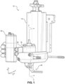
- the terms “horizontal,” “lateral,” and “vertical” are used to describe the orthogonal directional components of various components of the applicator system 10, as designated by the longitudinal direction 2, lateral direction 4, and vertical direction 6. It should be appreciated that while the longitudinal and lateral directions 2 and 4 are illustrated as extending along a horizontal plane, and the vertical direction 6 extends in a direction that is normal to the horizontal plane, the planes that encompass the various directions may differ during use.
- the pump 16 includes a circumferential chamber 54 defined between an outer surface of the bottom component 32c of the body 31 and an inner surface of the middle component 32b.
- the circumferential chamber 54 is fluidly connected to the material supply 12, such that the circumferential chamber 54 is configured to receive material from the material supply 12 and allow the material to flow through the circumferential chamber 54 to radial holes 56 defined within the bottom component 32c. The material can then flow through the radial holes 56 to the lower chamber 38.
- the radial holes 56 comprise four radial holes spaced equidistantly circumferentially around the bottom component 32c. However, it is contemplated that the radial holes 56 can comprise more or less holes, as well as holes having non-equidistant spacing.
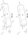
- the nozzle assembly 28 can include a nozzle body 29.
- the nozzle body 29 can include an upper flange 100, an arm 104 extending from the upper flange 100, and a nozzle head 108 attached to the arm 104 opposite the upper flange 100.
- the upper flange 100 can include an inlet port 110 on its upper surface 100a, as well as two bores 112 that extend through the upper flange 100.
- the upper surface 100a contacts the pump 16 and the inlet port 110 can be in fluid communication with the outlet channel 64 of the pump 16, such that the nozzle assembly 28 receives the material from the pump 16 through the inlet port 110.
- the arm 104 is shown as extending downwards from the upper flange 100 along a direction that is angularly offset from the vertical direction 6. Though one particular angular orientation between the arm 104 and the upper flange 100 is shown, in other embodiments the arm 104 can extend downward from the upper flange 100 along the vertical direction 6, or at other angular offsets from the vertical direction 6.
- the nozzle head 108 extends substantially horizontal away from the arm 104, and defines the portion of the nozzle assembly 28 through which material is dispensed onto a substrate.
- the nozzle assembly 28 includes a baffle plate 101 and a cover plate 102 attached to the nozzle head 108, which will be discussed further below.
- the nozzle body 29 can be monolithic, and can be formed through casting, injection molding, etc.
- the plug 164 can threadedly engage the nozzle head 108 to seal the flush bore 122, though it should be appreciated that the plug 164 can engage the nozzle head 108 through other means. Though shown as extending from the passage 116 to the second side surface 108d, the flush bore 122 can alternatively extend from the passage 116 to any of the surfaces 108a-108fas desired.
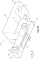
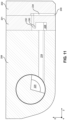
- the nozzle head 108 also includes a nozzle recess 132 extending from the front surface 108e into the nozzle head 108.
- the nozzle recess 132 can be defined by an upper surface 130a that extends inward from the front surface 108e of the nozzle head 108, a lower surface 130b that extends inward from the front surface 108e opposite the upper surface 130a, a first side surface 130c that extends inward from the front surface 108e and extends from the upper surface 130a to the lower surface 130b, and a second side surface 130d that extends inward from the front surface 108e opposite the first side surface 130c, as well as from the upper surface 130a to the lower surface 130b.
- the baffle plate 101 has an upper surface 101a, a lower surface 101b opposite the upper surface 101a along the vertical direction 6, a first side surface 101c, a second side surface 101d opposite the first side surface 101c along the lateral direction 4, a front surface 101e, and a rear surface 101f opposite the front surface 101e along the longitudinal direction 2.
- the baffle plate 101 can have a substantially rectangular shape.
- the nozzle recess 132 is sized to receive the baffle plate 101 such that the shape of the nozzle recess 132 and the shape of the baffle plate 101 generally conform to each other.
- the baffle plate 101 can be suitably installed within the nozzle head 108 by pressing the baffle plate 101 within the nozzle recess 132.
- the front surface 101e of the baffle plate 101 can be substantially coplanar with the front surface 108e of the nozzle head 108, though other configurations are envisioned.
- any of the upper, lower, first side, or second side surfaces 130a-130d can have an increased roughness or texture for engaging the baffle plate 101.
- any of the upper, lower, first side, or second side surfaces 101a-101d of the baffle plate 101 can have an increased roughness or texture for engaging the surfaces 130a-130d that define the nozzle recess 132.
- the nozzle assembly 28 can include sealing elements around the baffle plate 101 that provide a fluid seal between the nozzle head 108 and the baffle plate 101.
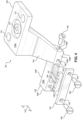
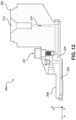
- a cover plate 102 is attached to the nozzle head 108 to secure the baffle plate 101 within the nozzle recess 132.
- the cover plate 102 can have an upper surface 102a, a bottom surface 102b opposite the upper surface 102a along the vertical direction 6, a first side surface 101c, a second side surface 101d opposite the first side surface 101c along the lateral direction 4, a front surface 101e, and a rear surface 101f opposite the front surface 101e along the longitudinal direction 2.
- the cover plate 102 can have a substantially rectangular shape.
- the cover plate 102 can further include an extension 156 that extends from the bottom surface 102b along the vertical direction 6, as well as from the rear surface 102f towards the front surface 102e.
- the extension 156 may extend partially towards the front surface 102e, or completely to the front surface 102e. As depicted, the extension 156 is spaced from the first and second side surfaces 102c, 102d, though it is contemplated that the extension 156 can extend to one or both of the first and second side surfaces 102c, 102d. Additionally, the cover plate 102 can include a recess 148 that extends into the cover plate 102 from the rear surface 102f. The cover plate 102 can include an inner recess surface 102j that can extend along the lateral and vertical directions 4, 6, and is between and substantially parallel to the front and rear surfaces 102e, 102f.
- an outlet passage 136 is defined between the baffle plate 101 and the cover plate 102, where the outlet passage 136 is fluidly connected to the fluid cavity 124 through the passage 128, and thus the cutout 144 of the baffle plate 101.
- the outlet passage 136 can define a short length along the longitudinal direction 2, but a comparatively larger width along the lateral direction 4.
- the outlet passage 136 can be partially defined by the recess 148 of the cover plate 102.
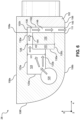
- the material After flowing into the fluid cavity 228, the material can flow upwards through the fluid cavity 228 under the pressure of material entering the fluid cavity 228, through the passage 232 defined by the baffle plate 201, and to the outlet passage 234.
- the passage 232 extends longitudinally through the baffle plate 201 and is positioned vertically between the upper and lower surfaces of the baffle plate 201, such that the passage 232 is solely defined by the baffle plate 201.
- the material then flows through the outlet passage 234 and through the outlet 240 defined between the cover plate 202 and the baffle plate 201, and onto a substrate.
- the cover plate 202 can be secured to the nozzle head 208 using screws 248, which can extend through the cover plate 202, the baffle plate 201, and threadingly engage the nozzle head 208.
- screws 248 which can extend through the cover plate 202, the baffle plate 201, and threadingly engage the nozzle head 208.
- the components of the nozzle assembly 28, 28a can be easily assembled, cleaned, and replaced, leading to simplicity in operation and maintenance. Further, the segmented nature of the passages within the nozzle heads 108, 208 can lead to the ability to dispense amounts of the material with greater accuracy.
Landscapes
- Coating Apparatus (AREA)
- Nozzles (AREA)
Claims (14)
- Eine Düsenanordnung (28) zum Ausgeben eines Materials, wobei die Düsenanordnung (28) umfasst:eine Düse mit einem Düsenkopf (108), wobei der Düsenkopf (108) einen Körper (29) aufweist, der eine Seitenfläche (108c, 108d) und eine Düsenaussparung (132) umfasst, die sich von der Seitenfläche (108c, 108d) in den Körper (29) hinein erstreckt;eine Ablenkplatte (101) mit einem Ausschnitt (144), der sich durch die Ablenkplatte (101) erstreckt, wobei die Ablenkplatte (101) in der Düsenaussparung (132) aufgenommen ist, so dass der Düsenkopf (108) und die Ablenkplatte (101) einen Hohlraum (124) bilden; undeine Abdeckplatte (102), die an dem Düsenkopf (108) so angebracht ist, dass die Abdeckplatte (102) die Ablenkplatte (101) innerhalb der Düsenaussparung (132) sichert, wobei ein Auslassdurchgang (136) zwischen der Ablenkplatte (101) und der Abdeckplatte (102) definiert ist, wobei der Auslassdurchgang (136) durch den Ausschnitt (144) der Ablenkplatte (101) mit dem Hohlraum (124) in Fluidverbindung steht, dadurch gekennzeichnet, dass die Ablenkplatte (101) eine obere Fläche (101a) aufweist, eine untere Fläche (101b) gegenüber der oberen Fläche (101a) entlang einer vertikalen Richtung (6), eine vordere Fläche (103e) und eine hintere Fläche (103f) gegenüber der vorderen Fläche (103e) entlang einer Längsrichtung (2), die senkrecht zu der vertikalen Richtung (6) ist, unddadurch gekennzeichnet, dass sich der Ausschnitt (144) 1) von der oberen Fläche (101a) in die Ablenkplatte (101) und 2) von der vorderen Fläche (103e) zur hinteren Fläche (103f) erstreckt.
- Düsenanordnung (28) nach Anspruch 1, wobei der Hohlraum (124) eine erste Höhe (H1), gemessen entlang einer vertikalen Richtung (6), aufweist und wobei die Düsenaussparung (132) eine zweite Höhe (H2), gemessen entlang der vertikalen Richtung (6), aufweist, die größer ist als die erste Höhe (H1).
- Düsenanordnung (28) nach Anspruch 2, wobei die vordere Fläche (103e) der Ablenkplatte (101) im Wesentlichen koplanar mit der Seitenfläche (103c) des Düsenkopfes (108) ist, wenn die Ablenkplatte (103) in der Düsenaussparung (132) aufgenommen ist.
- Düsenanordnung (28) nach Anspruch 2, wobei die Ablenkplatte (101) eine erste und eine zweite Ausschnittsfläche (101i, 101h) aufweist, die sich von der oberen Fläche (101a) entlang der vertikalen Richtung (6) erstrecken, und eine dritte Ausschnittsfläche (101g), die sich von der ersten Ausschnittsfläche (101i) zur zweiten Ausschnittsfläche (101h) erstreckt, so dass die erste, zweite und dritte Ausschnittsfläche (101i, 101h, 101g) den Ausschnitt (144) definieren.
- Düsenanordnung (28) nach Anspruch 4, wobei die dritte Ausschnittsfläche (101g) zwischen der oberen und der unteren Fläche (101a, 101b) entlang der vertikalen Richtung (6) angeordnet ist.
- Düsenanordnung (28) nach Anspruch 1, wobei die Düse ferner umfasst:einen oberen Flansch (100) mit einem Einlass (110) zur Aufnahme des Materials; undeinen Arm (104), der sich von dem oberen Flansch (100) zu dem Düsenkopf (108) erstreckt, wobei der Arm (104) einen Durchgang (116) in Fluidverbindung mit dem Einlass (110) und dem Hohlraum (124) definiert.
- Düsenanordnung (28) nach Anspruch 6, die ferner ein Rückschlagventil (207) umfasst, das teilweise in dem Durchgang (216) des Arms (204) angeordnet ist.
- Düsenanordnung (28) nach Anspruch 1, wobei die Abdeckplatte (102) eine vordere Fläche (101e), eine hintere Fläche (101f), die der vorderen Fläche (101e) entlang einer Längsrichtung (2) gegenüberliegt, und eine Auslassaussparung (148) definiert, die sich von der hinteren Fläche (101f) in die Abdeckplatte (102) erstreckt, wobei die Auslassaussparung (148) zumindest teilweise den Auslasskanal (136) definiert.
- Düsenanordnung (28) nach Anspruch 1, wobei:
die Abdeckplatte (102) eine erste Verlängerung (111) aufweist, die sich von der Abdeckplatte (102) benachbart zu einem Auslass (136) der Düsenanordnung (28, 28a) in einer vertikalen Richtung (6) nach unten erstreckt, und
der Düsenkopf (108) eine zweite Verlängerung (156) aufweist, die sich entlang der vertikalen Richtung (6) neben dem Auslass (140) nach unten erstreckt. - Düsenanordnung (28) nach Anspruch 1, wobei die Ablenkplatte (101) einen Flansch (230) aufweist, der sich in den Hohlraum (228) erstreckt.
- Düsenanordnung (28) nach Anspruch 1, wobei der Düsenkopf (208) eine Vielzahl von seitlich ausgerichteten Kanälen (224) aufweist, die sich von einem durch den Düsenkopf (208) definierten Transferkanal (220) zu dem Hohlraum (228) erstrecken.
- Ein Auftragssystem (10) zum Auftragen eines Materials auf ein Substrat, wobei das Auftragssystem (10) umfasst:einen Materialvorrat (12) zur Lagerung und Erwärmung des Materials;eine Pumpe (16), die mit dem Materialvorrat (12) verbunden ist;ein Ventil (20) zur Steuerung des Betriebs der Pumpe (16); unddie Düsenanordnung (28) nach Anspruch 1, die so konfiguriert ist, dass sie das Material von der Pumpe (16) erhält und das Material auf das Substrat abgibt.
- Auftragssystem (10) nach Anspruch 12, wobei die Pumpe (16) einen Ventilsitz (60) und einen Schlagbolzen (48) aufweist, der zwischen einer 1) zurückgezogenen Position, in der der Schlagbolzen (48) von dem Ventilsitz (60) beabstandet ist, und 2) einer ausgefahrenen Position, in der der Schlagbolzen (48) den Ventilsitz (60) berührt, übergeht, wobei der Übergang des Schlagbolzens (48) von der zurückgezogenen Position in die ausgefahrene Position eine Menge des Materials zu der Düsenanordnung (28) pumpt.
- Auftragssystem (10) nach Anspruch 12, wobei das Ventil (20) ein pneumatisches Ventil ist.
Applications Claiming Priority (2)
| Application Number | Priority Date | Filing Date | Title |
|---|---|---|---|
| CN201710334374.0A CN108855657B (zh) | 2017-05-12 | 2017-05-12 | 喷嘴和包括它的涂胶系统 |
| PCT/US2018/031728 WO2018208876A1 (en) | 2017-05-12 | 2018-05-09 | Nozzle and applicator system comprising the same |
Publications (2)
| Publication Number | Publication Date |
|---|---|
| EP3621748A1 EP3621748A1 (de) | 2020-03-18 |
| EP3621748B1 true EP3621748B1 (de) | 2024-07-03 |
Family
ID=62245475
Family Applications (1)
| Application Number | Title | Priority Date | Filing Date |
|---|---|---|---|
| EP18727553.2A Active EP3621748B1 (de) | 2017-05-12 | 2018-05-09 | Düse und applikatorsystem damit |
Country Status (9)
| Country | Link |
|---|---|
| US (2) | US11724266B2 (de) |
| EP (1) | EP3621748B1 (de) |
| JP (1) | JP7191855B2 (de) |
| KR (1) | KR102559123B1 (de) |
| CN (1) | CN108855657B (de) |
| ES (1) | ES2986437T3 (de) |
| HU (1) | HUE068513T2 (de) |
| PL (1) | PL3621748T3 (de) |
| WO (1) | WO2018208876A1 (de) |
Families Citing this family (3)
| Publication number | Priority date | Publication date | Assignee | Title |
|---|---|---|---|---|
| US12083552B2 (en) * | 2018-11-21 | 2024-09-10 | Nordson Corporation | Adhesive dispenser with slotted nozzle assembly |
| CN215695356U (zh) * | 2021-04-16 | 2022-02-01 | 诺信公司 | 喷头组件、分配系统、电极片材条带以及电极 |
| CN114884292B (zh) * | 2022-07-07 | 2022-11-01 | 宁波震裕科技股份有限公司 | 一种电机粘胶铁芯制造装置及其制造方法 |
Citations (1)
| Publication number | Priority date | Publication date | Assignee | Title |
|---|---|---|---|---|
| US5320679A (en) * | 1993-07-28 | 1994-06-14 | Eastman Kodak Company | Coating hopper with criss-cross flow circuit |
Family Cites Families (33)
| Publication number | Priority date | Publication date | Assignee | Title |
|---|---|---|---|---|
| US3303972A (en) * | 1965-10-23 | 1967-02-14 | Sels Peter J Van Loben | Dispenser mounting assembly |
| DE3019280A1 (de) * | 1980-05-21 | 1981-12-03 | Röhm GmbH, 6100 Darmstadt | Breitschlitzextrusionsduese mit verstellbarem betriebspunkt |
| US4411614A (en) * | 1982-02-18 | 1983-10-25 | E. I. Du Pont De Nemours & Co. | Removable contoured insert for an extrusion die |
| DE3522320A1 (de) | 1985-06-21 | 1987-01-02 | Vepa Ag | Vorrichtung zum aufbringen eines fluessigkeitsfilmes grosser breite auf eine warenbahn |
| US4901095A (en) * | 1988-11-10 | 1990-02-13 | Markem Corporation | Ink jet printing apparatus with adjustable print head |
| US5266019A (en) * | 1990-10-31 | 1993-11-30 | Farber Claude W | Apparatus and method for applying a flowable material to a surface for forming molding thereon |
| US5329964A (en) * | 1993-09-09 | 1994-07-19 | Eastman Kodak Company | Criss-cross hopper including non-contacting inserts |
| US5478224A (en) * | 1994-02-04 | 1995-12-26 | Illinois Tool Works Inc. | Apparatus for depositing a material on a substrate and an applicator head therefor |
| US5525376A (en) * | 1995-02-02 | 1996-06-11 | Minnesota Mining And Manufacturing Company | Multiple layer coating method |
| EP1083999A4 (de) * | 1998-04-17 | 2004-06-02 | Nordson Corp | Verfahren und vorrichtung zum aufbringen eines kontrollierten musters aus faserförmigem material auf ein bewegendes substrat |
| JP2001029861A (ja) * | 1999-07-21 | 2001-02-06 | Dainippon Printing Co Ltd | ダイヘッド |
| US6352424B1 (en) * | 1999-12-30 | 2002-03-05 | Extrusion Dies, Inc. | Extrusion die membrane assembly |
| CN1812844A (zh) * | 2003-07-04 | 2006-08-02 | 英克罗有限公司 | 喷嘴结构 |
| JP4419022B2 (ja) * | 2005-11-04 | 2010-02-24 | 井上金属工業株式会社 | ダイ塗工装置 |
| JP4752492B2 (ja) | 2005-12-22 | 2011-08-17 | 凸版印刷株式会社 | ダイ塗工ヘッド |
| DE202006014743U1 (de) | 2006-09-22 | 2006-11-23 | Nordson Corporation, Westlake | Vorrichtung zum Auftragen von Fluiden wie Klebstoff, insbesondere Schmelzkleber |
| JP4830754B2 (ja) | 2006-09-25 | 2011-12-07 | 凸版印刷株式会社 | 塗布装置および塗膜の形成方法 |
| CN201008812Y (zh) * | 2007-02-15 | 2008-01-23 | 深圳市宜极邦机电设备有限公司 | 喷射式点胶阀 |
| US8123511B2 (en) * | 2007-05-03 | 2012-02-28 | Cloeren Incorporated | Decoupled transverse flow metering gap and lip gap |
| KR100806845B1 (ko) | 2007-06-11 | 2008-02-22 | 주식회사 케이씨텍 | 기판처리용 약액 도포 노즐 |
| US7871058B2 (en) * | 2007-07-25 | 2011-01-18 | Illinois Tool Works Inc. | Dual inline solenoid-actuated hot melt adhesive dispensing valve assembly |
| JP2009148716A (ja) | 2007-12-21 | 2009-07-09 | Chugai Ro Co Ltd | 塗装装置 |
| US8171973B2 (en) * | 2008-01-29 | 2012-05-08 | Nordson Corporation | Nozzle and related apparatus and method for dispensing molten thermoplastic material |
| EP2582470B1 (de) | 2010-06-15 | 2020-09-09 | 3M Innovative Properties Company | Verteilerkanal mit mehreren dispensiernadeln |
| US20120031327A1 (en) | 2010-08-04 | 2012-02-09 | Love Iii Franklin S | Apparatus for controlled application of liquid streams to a substrate with diverted liquid collection system |
| JP2012179502A (ja) * | 2011-02-28 | 2012-09-20 | Nordson Corp | スロットノズル組立体及びシム板 |
| TWI496625B (zh) * | 2012-06-29 | 2015-08-21 | Univ Nat Taiwan | 塗佈模組 |
| JP2015020089A (ja) | 2013-07-16 | 2015-02-02 | 株式会社豊田自動織機 | 塗工装置及び塗工ヘッド |
| CN203540805U (zh) * | 2013-10-31 | 2014-04-16 | 刘飞 | 一种带冷却功能的气动式喷射阀 |
| CN203540815U (zh) * | 2013-10-31 | 2014-04-16 | 刘飞 | 一种气动式喷射阀 |
| CN104526971A (zh) * | 2014-12-08 | 2015-04-22 | 浙江工商职业技术学院 | 一种带保压功能的热流道喷嘴 |
| US10090453B2 (en) | 2015-05-22 | 2018-10-02 | Nordson Corporation | Piezoelectric jetting system and method |
| JP6285510B2 (ja) | 2016-08-08 | 2018-02-28 | 武蔵エンジニアリング株式会社 | 液体材料の吐出装置および方法 |
-
2017
- 2017-05-12 CN CN201710334374.0A patent/CN108855657B/zh active Active
-
2018
- 2018-05-09 US US16/608,824 patent/US11724266B2/en active Active
- 2018-05-09 HU HUE18727553A patent/HUE068513T2/hu unknown
- 2018-05-09 PL PL18727553.2T patent/PL3621748T3/pl unknown
- 2018-05-09 JP JP2019562648A patent/JP7191855B2/ja active Active
- 2018-05-09 EP EP18727553.2A patent/EP3621748B1/de active Active
- 2018-05-09 ES ES18727553T patent/ES2986437T3/es active Active
- 2018-05-09 WO PCT/US2018/031728 patent/WO2018208876A1/en not_active Ceased
- 2018-05-09 KR KR1020197036483A patent/KR102559123B1/ko active Active
-
2023
- 2023-06-15 US US18/335,193 patent/US20230321672A1/en active Pending
Patent Citations (1)
| Publication number | Priority date | Publication date | Assignee | Title |
|---|---|---|---|---|
| US5320679A (en) * | 1993-07-28 | 1994-06-14 | Eastman Kodak Company | Coating hopper with criss-cross flow circuit |
Also Published As
| Publication number | Publication date |
|---|---|
| US11724266B2 (en) | 2023-08-15 |
| JP7191855B2 (ja) | 2022-12-19 |
| CN108855657B (zh) | 2021-08-13 |
| KR102559123B1 (ko) | 2023-07-26 |
| CN108855657A (zh) | 2018-11-23 |
| KR20200007006A (ko) | 2020-01-21 |
| PL3621748T3 (pl) | 2024-11-25 |
| WO2018208876A1 (en) | 2018-11-15 |
| US20230321672A1 (en) | 2023-10-12 |
| JP2020519443A (ja) | 2020-07-02 |
| EP3621748A1 (de) | 2020-03-18 |
| HUE068513T2 (hu) | 2024-12-28 |
| ES2986437T3 (es) | 2024-11-11 |
| US20200197958A1 (en) | 2020-06-25 |
Similar Documents
| Publication | Publication Date | Title |
|---|---|---|
| US20230321672A1 (en) | Nozzle and applicator system comprising the same | |
| KR102228891B1 (ko) | 도징 시스템, 도징 방법, 및 제조 방법 | |
| JP6745262B2 (ja) | ノンインパクト噴射吐出モジュール及び方法 | |
| CN110935592A (zh) | 点胶装置及具有它的点胶设备 | |
| JP5856332B1 (ja) | 微量流体流出方法および微量流体ディスペンサ | |
| US12083552B2 (en) | Adhesive dispenser with slotted nozzle assembly | |
| KR20070111486A (ko) | 점성 액체 분사 시스템, 밸브 및 방법 | |
| IL46611A (en) | Spraying device for the automatic uniform application of a substance to a surface | |
| US11975494B2 (en) | Nozzle and applicator system for fabric bonding | |
| JP2013517124A (ja) | 液体材料を所望のパターンで噴射する装置及び方法 | |
| KR20180137727A (ko) | 디스펜싱 장치 | |
| CN211802048U (zh) | 一种真空点胶机用的截止阀结构 | |
| KR101672784B1 (ko) | 노즐 유닛 및 이를 이용하는 도포액 도포 장치 | |
| CN120662496A (zh) | 用于点胶机的喷嘴装置以及点胶机 | |
| KR20260019258A (ko) | 이형제 도포장치가 결합된 크로스헤드 | |
| JP2001347195A (ja) | 噴出ヘッド | |
| KR20150039901A (ko) | 기판 코터 장치 |
Legal Events
| Date | Code | Title | Description |
|---|---|---|---|
| STAA | Information on the status of an ep patent application or granted ep patent |
Free format text: STATUS: UNKNOWN |
|
| STAA | Information on the status of an ep patent application or granted ep patent |
Free format text: STATUS: THE INTERNATIONAL PUBLICATION HAS BEEN MADE |
|
| PUAI | Public reference made under article 153(3) epc to a published international application that has entered the european phase |
Free format text: ORIGINAL CODE: 0009012 |
|
| STAA | Information on the status of an ep patent application or granted ep patent |
Free format text: STATUS: REQUEST FOR EXAMINATION WAS MADE |
|
| 17P | Request for examination filed |
Effective date: 20191212 |
|
| AK | Designated contracting states |
Kind code of ref document: A1 Designated state(s): AL AT BE BG CH CY CZ DE DK EE ES FI FR GB GR HR HU IE IS IT LI LT LU LV MC MK MT NL NO PL PT RO RS SE SI SK SM TR |
|
| AX | Request for extension of the european patent |
Extension state: BA ME |
|
| DAV | Request for validation of the european patent (deleted) | ||
| DAX | Request for extension of the european patent (deleted) | ||
| STAA | Information on the status of an ep patent application or granted ep patent |
Free format text: STATUS: EXAMINATION IS IN PROGRESS |
|
| 17Q | First examination report despatched |
Effective date: 20201123 |
|
| P01 | Opt-out of the competence of the unified patent court (upc) registered |
Effective date: 20230528 |
|
| GRAP | Despatch of communication of intention to grant a patent |
Free format text: ORIGINAL CODE: EPIDOSNIGR1 |
|
| STAA | Information on the status of an ep patent application or granted ep patent |
Free format text: STATUS: GRANT OF PATENT IS INTENDED |
|
| INTG | Intention to grant announced |
Effective date: 20240108 |
|
| RIC1 | Information provided on ipc code assigned before grant |
Ipc: B05B 9/04 20060101ALN20231219BHEP Ipc: B05B 9/00 20060101ALN20231219BHEP Ipc: B05C 11/10 20060101ALN20231219BHEP Ipc: B05C 5/00 20060101ALN20231219BHEP Ipc: B05C 5/02 20060101ALI20231219BHEP Ipc: B05B 1/36 20060101ALI20231219BHEP Ipc: B05B 1/04 20060101ALI20231219BHEP Ipc: B05B 1/30 20060101AFI20231219BHEP |
|
| GRAS | Grant fee paid |
Free format text: ORIGINAL CODE: EPIDOSNIGR3 |
|
| GRAA | (expected) grant |
Free format text: ORIGINAL CODE: 0009210 |
|
| STAA | Information on the status of an ep patent application or granted ep patent |
Free format text: STATUS: THE PATENT HAS BEEN GRANTED |
|
| AK | Designated contracting states |
Kind code of ref document: B1 Designated state(s): AL AT BE BG CH CY CZ DE DK EE ES FI FR GB GR HR HU IE IS IT LI LT LU LV MC MK MT NL NO PL PT RO RS SE SI SK SM TR |
|
| REG | Reference to a national code |
Ref country code: CH Ref legal event code: EP |
|
| REG | Reference to a national code |
Ref country code: DE Ref legal event code: R096 Ref document number: 602018071271 Country of ref document: DE |
|
| REG | Reference to a national code |
Ref country code: LT Ref legal event code: MG9D |
|
| REG | Reference to a national code |
Ref country code: NL Ref legal event code: MP Effective date: 20240703 |
|
| REG | Reference to a national code |
Ref country code: ES Ref legal event code: FG2A Ref document number: 2986437 Country of ref document: ES Kind code of ref document: T3 Effective date: 20241111 |
|
| PG25 | Lapsed in a contracting state [announced via postgrant information from national office to epo] |
Ref country code: PT Free format text: LAPSE BECAUSE OF FAILURE TO SUBMIT A TRANSLATION OF THE DESCRIPTION OR TO PAY THE FEE WITHIN THE PRESCRIBED TIME-LIMIT Effective date: 20241104 |
|
| REG | Reference to a national code |
Ref country code: AT Ref legal event code: MK05 Ref document number: 1699276 Country of ref document: AT Kind code of ref document: T Effective date: 20240703 |
|
| PG25 | Lapsed in a contracting state [announced via postgrant information from national office to epo] |
Ref country code: NL Free format text: LAPSE BECAUSE OF FAILURE TO SUBMIT A TRANSLATION OF THE DESCRIPTION OR TO PAY THE FEE WITHIN THE PRESCRIBED TIME-LIMIT Effective date: 20240703 |
|
| REG | Reference to a national code |
Ref country code: HU Ref legal event code: AG4A Ref document number: E068513 Country of ref document: HU |
|
| PG25 | Lapsed in a contracting state [announced via postgrant information from national office to epo] |
Ref country code: PT Free format text: LAPSE BECAUSE OF FAILURE TO SUBMIT A TRANSLATION OF THE DESCRIPTION OR TO PAY THE FEE WITHIN THE PRESCRIBED TIME-LIMIT Effective date: 20241104 Ref country code: NL Free format text: LAPSE BECAUSE OF FAILURE TO SUBMIT A TRANSLATION OF THE DESCRIPTION OR TO PAY THE FEE WITHIN THE PRESCRIBED TIME-LIMIT Effective date: 20240703 |
|
| PG25 | Lapsed in a contracting state [announced via postgrant information from national office to epo] |
Ref country code: NO Free format text: LAPSE BECAUSE OF FAILURE TO SUBMIT A TRANSLATION OF THE DESCRIPTION OR TO PAY THE FEE WITHIN THE PRESCRIBED TIME-LIMIT Effective date: 20241003 |
|
| PG25 | Lapsed in a contracting state [announced via postgrant information from national office to epo] |
Ref country code: GR Free format text: LAPSE BECAUSE OF FAILURE TO SUBMIT A TRANSLATION OF THE DESCRIPTION OR TO PAY THE FEE WITHIN THE PRESCRIBED TIME-LIMIT Effective date: 20241004 Ref country code: FI Free format text: LAPSE BECAUSE OF FAILURE TO SUBMIT A TRANSLATION OF THE DESCRIPTION OR TO PAY THE FEE WITHIN THE PRESCRIBED TIME-LIMIT Effective date: 20240703 |
|
| PG25 | Lapsed in a contracting state [announced via postgrant information from national office to epo] |
Ref country code: BG Free format text: LAPSE BECAUSE OF FAILURE TO SUBMIT A TRANSLATION OF THE DESCRIPTION OR TO PAY THE FEE WITHIN THE PRESCRIBED TIME-LIMIT Effective date: 20240703 |
|
| PG25 | Lapsed in a contracting state [announced via postgrant information from national office to epo] |
Ref country code: LV Free format text: LAPSE BECAUSE OF FAILURE TO SUBMIT A TRANSLATION OF THE DESCRIPTION OR TO PAY THE FEE WITHIN THE PRESCRIBED TIME-LIMIT Effective date: 20240703 |
|
| PG25 | Lapsed in a contracting state [announced via postgrant information from national office to epo] |
Ref country code: IS Free format text: LAPSE BECAUSE OF FAILURE TO SUBMIT A TRANSLATION OF THE DESCRIPTION OR TO PAY THE FEE WITHIN THE PRESCRIBED TIME-LIMIT Effective date: 20241103 Ref country code: AT Free format text: LAPSE BECAUSE OF FAILURE TO SUBMIT A TRANSLATION OF THE DESCRIPTION OR TO PAY THE FEE WITHIN THE PRESCRIBED TIME-LIMIT Effective date: 20240703 |
|
| PG25 | Lapsed in a contracting state [announced via postgrant information from national office to epo] |
Ref country code: HR Free format text: LAPSE BECAUSE OF FAILURE TO SUBMIT A TRANSLATION OF THE DESCRIPTION OR TO PAY THE FEE WITHIN THE PRESCRIBED TIME-LIMIT Effective date: 20240703 Ref country code: CZ Free format text: LAPSE BECAUSE OF FAILURE TO SUBMIT A TRANSLATION OF THE DESCRIPTION OR TO PAY THE FEE WITHIN THE PRESCRIBED TIME-LIMIT Effective date: 20240703 |
|
| PG25 | Lapsed in a contracting state [announced via postgrant information from national office to epo] |
Ref country code: RS Free format text: LAPSE BECAUSE OF FAILURE TO SUBMIT A TRANSLATION OF THE DESCRIPTION OR TO PAY THE FEE WITHIN THE PRESCRIBED TIME-LIMIT Effective date: 20241003 |
|
| PG25 | Lapsed in a contracting state [announced via postgrant information from national office to epo] |
Ref country code: RS Free format text: LAPSE BECAUSE OF FAILURE TO SUBMIT A TRANSLATION OF THE DESCRIPTION OR TO PAY THE FEE WITHIN THE PRESCRIBED TIME-LIMIT Effective date: 20241003 Ref country code: NO Free format text: LAPSE BECAUSE OF FAILURE TO SUBMIT A TRANSLATION OF THE DESCRIPTION OR TO PAY THE FEE WITHIN THE PRESCRIBED TIME-LIMIT Effective date: 20241003 Ref country code: LV Free format text: LAPSE BECAUSE OF FAILURE TO SUBMIT A TRANSLATION OF THE DESCRIPTION OR TO PAY THE FEE WITHIN THE PRESCRIBED TIME-LIMIT Effective date: 20240703 Ref country code: IS Free format text: LAPSE BECAUSE OF FAILURE TO SUBMIT A TRANSLATION OF THE DESCRIPTION OR TO PAY THE FEE WITHIN THE PRESCRIBED TIME-LIMIT Effective date: 20241103 Ref country code: HR Free format text: LAPSE BECAUSE OF FAILURE TO SUBMIT A TRANSLATION OF THE DESCRIPTION OR TO PAY THE FEE WITHIN THE PRESCRIBED TIME-LIMIT Effective date: 20240703 Ref country code: GR Free format text: LAPSE BECAUSE OF FAILURE TO SUBMIT A TRANSLATION OF THE DESCRIPTION OR TO PAY THE FEE WITHIN THE PRESCRIBED TIME-LIMIT Effective date: 20241004 Ref country code: FI Free format text: LAPSE BECAUSE OF FAILURE TO SUBMIT A TRANSLATION OF THE DESCRIPTION OR TO PAY THE FEE WITHIN THE PRESCRIBED TIME-LIMIT Effective date: 20240703 Ref country code: CZ Free format text: LAPSE BECAUSE OF FAILURE TO SUBMIT A TRANSLATION OF THE DESCRIPTION OR TO PAY THE FEE WITHIN THE PRESCRIBED TIME-LIMIT Effective date: 20240703 Ref country code: BG Free format text: LAPSE BECAUSE OF FAILURE TO SUBMIT A TRANSLATION OF THE DESCRIPTION OR TO PAY THE FEE WITHIN THE PRESCRIBED TIME-LIMIT Effective date: 20240703 Ref country code: AT Free format text: LAPSE BECAUSE OF FAILURE TO SUBMIT A TRANSLATION OF THE DESCRIPTION OR TO PAY THE FEE WITHIN THE PRESCRIBED TIME-LIMIT Effective date: 20240703 |
|
| REG | Reference to a national code |
Ref country code: DE Ref legal event code: R097 Ref document number: 602018071271 Country of ref document: DE |
|
| PG25 | Lapsed in a contracting state [announced via postgrant information from national office to epo] |
Ref country code: SM Free format text: LAPSE BECAUSE OF FAILURE TO SUBMIT A TRANSLATION OF THE DESCRIPTION OR TO PAY THE FEE WITHIN THE PRESCRIBED TIME-LIMIT Effective date: 20240703 Ref country code: RO Free format text: LAPSE BECAUSE OF FAILURE TO SUBMIT A TRANSLATION OF THE DESCRIPTION OR TO PAY THE FEE WITHIN THE PRESCRIBED TIME-LIMIT Effective date: 20240703 Ref country code: DK Free format text: LAPSE BECAUSE OF FAILURE TO SUBMIT A TRANSLATION OF THE DESCRIPTION OR TO PAY THE FEE WITHIN THE PRESCRIBED TIME-LIMIT Effective date: 20240703 |
|
| PG25 | Lapsed in a contracting state [announced via postgrant information from national office to epo] |
Ref country code: EE Free format text: LAPSE BECAUSE OF FAILURE TO SUBMIT A TRANSLATION OF THE DESCRIPTION OR TO PAY THE FEE WITHIN THE PRESCRIBED TIME-LIMIT Effective date: 20240703 |
|
| PG25 | Lapsed in a contracting state [announced via postgrant information from national office to epo] |
Ref country code: SK Free format text: LAPSE BECAUSE OF FAILURE TO SUBMIT A TRANSLATION OF THE DESCRIPTION OR TO PAY THE FEE WITHIN THE PRESCRIBED TIME-LIMIT Effective date: 20240703 |
|
| PLBE | No opposition filed within time limit |
Free format text: ORIGINAL CODE: 0009261 |
|
| STAA | Information on the status of an ep patent application or granted ep patent |
Free format text: STATUS: NO OPPOSITION FILED WITHIN TIME LIMIT |
|
| 26N | No opposition filed |
Effective date: 20250404 |
|
| PGFP | Annual fee paid to national office [announced via postgrant information from national office to epo] |
Ref country code: PL Payment date: 20250429 Year of fee payment: 8 Ref country code: DE Payment date: 20250521 Year of fee payment: 8 |
|
| PGFP | Annual fee paid to national office [announced via postgrant information from national office to epo] |
Ref country code: GB Payment date: 20250527 Year of fee payment: 8 |
|
| PGFP | Annual fee paid to national office [announced via postgrant information from national office to epo] |
Ref country code: HU Payment date: 20250523 Year of fee payment: 8 |
|
| PGFP | Annual fee paid to national office [announced via postgrant information from national office to epo] |
Ref country code: IT Payment date: 20250527 Year of fee payment: 8 |
|
| PGFP | Annual fee paid to national office [announced via postgrant information from national office to epo] |
Ref country code: FR Payment date: 20250528 Year of fee payment: 8 |
|
| PGFP | Annual fee paid to national office [announced via postgrant information from national office to epo] |
Ref country code: CH Payment date: 20250601 Year of fee payment: 8 |
|
| PG25 | Lapsed in a contracting state [announced via postgrant information from national office to epo] |
Ref country code: SE Free format text: LAPSE BECAUSE OF FAILURE TO SUBMIT A TRANSLATION OF THE DESCRIPTION OR TO PAY THE FEE WITHIN THE PRESCRIBED TIME-LIMIT Effective date: 20240703 |
|
| PGFP | Annual fee paid to national office [announced via postgrant information from national office to epo] |
Ref country code: ES Payment date: 20250630 Year of fee payment: 8 |
|
| PG25 | Lapsed in a contracting state [announced via postgrant information from national office to epo] |
Ref country code: LU Free format text: LAPSE BECAUSE OF NON-PAYMENT OF DUE FEES Effective date: 20250509 |
|
| REG | Reference to a national code |
Ref country code: BE Ref legal event code: MM Effective date: 20250531 |
|
| PG25 | Lapsed in a contracting state [announced via postgrant information from national office to epo] |
Ref country code: MC Free format text: LAPSE BECAUSE OF FAILURE TO SUBMIT A TRANSLATION OF THE DESCRIPTION OR TO PAY THE FEE WITHIN THE PRESCRIBED TIME-LIMIT Effective date: 20240703 |
|
| PG25 | Lapsed in a contracting state [announced via postgrant information from national office to epo] |
Ref country code: IE Free format text: LAPSE BECAUSE OF NON-PAYMENT OF DUE FEES Effective date: 20250509 |
|
| PG25 | Lapsed in a contracting state [announced via postgrant information from national office to epo] |
Ref country code: BE Free format text: LAPSE BECAUSE OF NON-PAYMENT OF DUE FEES Effective date: 20250531 |