EP3621866B1 - System und verfahren zur detektion eines anomalen gangzustands eines schienenfahrzeugs - Google Patents
System und verfahren zur detektion eines anomalen gangzustands eines schienenfahrzeugs Download PDFInfo
- Publication number
- EP3621866B1 EP3621866B1 EP18728963.2A EP18728963A EP3621866B1 EP 3621866 B1 EP3621866 B1 EP 3621866B1 EP 18728963 A EP18728963 A EP 18728963A EP 3621866 B1 EP3621866 B1 EP 3621866B1
- Authority
- EP
- European Patent Office
- Prior art keywords
- railway vehicle
- abnormal gait
- condition
- detecting
- gait condition
- Prior art date
- Legal status (The legal status is an assumption and is not a legal conclusion. Google has not performed a legal analysis and makes no representation as to the accuracy of the status listed.)
- Active
Links
Images




Classifications
-
- B—PERFORMING OPERATIONS; TRANSPORTING
- B61—RAILWAYS
- B61K—AUXILIARY EQUIPMENT SPECIALLY ADAPTED FOR RAILWAYS, NOT OTHERWISE PROVIDED FOR
- B61K9/00—Railway vehicle profile gauges; Detecting or indicating overheating of components; Apparatus on locomotives or cars to indicate bad track sections; General design of track recording vehicles
- B61K9/12—Measuring or surveying wheel-rims
-
- G—PHYSICS
- G01—MEASURING; TESTING
- G01B—MEASURING LENGTH, THICKNESS OR SIMILAR LINEAR DIMENSIONS; MEASURING ANGLES; MEASURING AREAS; MEASURING IRREGULARITIES OF SURFACES OR CONTOURS
- G01B11/00—Measuring arrangements characterised by the use of optical techniques
- G01B11/24—Measuring arrangements characterised by the use of optical techniques for measuring contours or curvatures
- G01B11/25—Measuring arrangements characterised by the use of optical techniques for measuring contours or curvatures by projecting a pattern, e.g. one or more lines, moiré fringes on the object
- G01B11/2518—Projection by scanning of the object
Definitions
- the present invention is, in general, in the field of safety systems for a railway vehicle; in particular, the invention relates to a system and a method for detecting an abnormal gait condition of a railway vehicle.
- the abnormal gait condition may consist of a derailment condition and/or an instability condition of a bogie of a railway vehicle.
- the derailment or instability of railway vehicles is generally caused by four categories of undesirable events:
- WILD sensors are strain gauges or load cells that allow the vertical load that is transferred from the wheels to the rail to be measured. In this way the presence of defects on the wheel, such as an insufficiently circular shape, the presence of flat surfaces or other tread defects that generate abnormal loads on the rail and which may initiate a derailment may be evaluated.
- KR20120014092 describes a system based on sensors that measure the distance between the rail and the vehicle. In this system, a signal is provided only when one or more wheels have left their normal operating position. Which is to say, when the derailment has already happened.
- each vehicle is equipped with a monitoring device capable of detecting accelerometer and gyroscope signals. Consequently, for the signals, comparison rules, algorithms and tables are established to detect the moment when the travel conditions turn from a normal travel condition to an abnormal condition, which may coincide with a derailment.
- a device for monitoring the instability of a railway vehicle comprises a first accelerometer which provides an acceleration signal in response to the vibrations along a reference axis, a solid-state relay switchable between a closed condition and an open condition, and a programmable logic device, FPGA, connected to the accelerometer and to the solid-state relay.
- the programmable logic device includes non-volatile logic blocks for the simultaneous parallel execution of an instability monitoring algorithm to change the state of the relay based on a condition of instability of the acceleration signal.
- An object of the present invention is therefore to provide a system and a method for detecting an abnormal gait condition of a bogie of a railway vehicle which have a high degree of redundancy and reliability.
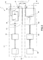
- the system for detecting an abnormal gait condition of a bogie of a railway vehicle 1 includes a first control chain C1 and a second control chain C2.
- the control chains C1 and C2 are connected to a digital output O to which a load L is connected.
- the digital output O is adapted to supply, or not to supply, the power needed to activate the load L.
- the power is supplied, or not supplied, to the load L according to the detection of an abnormal gait condition of the railway vehicle. In the configurations shown in figures 3 to 5 , power is not supplied to the load when a condition of potential abnormal gait of the railway vehicle is detected.
- the first control chain C1 comprises first sensor means S1 adapted to detect first detection data of the attitude and/or movement of the railway vehicle, and a first control unit U1 adapted to receive said first detection data of the attitude and/or of the movement of the railway vehicle from the first sensor means S1, executing a first computer program SW1 for checking an abnormal gait condition of the railway vehicle and controlling the first electronic control means E1 to supply or not to supply power to the load L.
- the second control chain C2 comprises second sensor means S2 adapted to detect second detection data of the attitude and/or movement of the railway vehicle, and a second control unit U2 adapted to receive said second detection data of the attitude and/or of the movement of the railway vehicle from the second sensor means S2, executing a second computer program SW2 for checking an abnormal gait condition and second electronic control means E2 to supply or not to supply power to the load L.
- the second sensor means S2 are different from said first sensor means S1, said second control unit U2 is different from said first control unit U1, said second computer program SW2 for checking an abnormal gait is different from said first computer program SW1 for checking an abnormal gait and the second electronic control means E2 are different from the first electronic control means E1.
- the first computer program SW1 will be able to exploit the first detection data received by the first sensor means S1 and the second computer program SW2 will be able to exploit the second detection data received from the second sensor means S2, to detect an abnormal gait condition.
- FIG 3 an embodiment of the system for detecting an abnormal gait condition of a bogie of a railway vehicle is illustrated, wherein the first electronic control means E1 and the second electronic control means E2 are connected in series and with the load L between two reference potentials B-, B+.
- the load L is disposed between a first node N1 of the first electronic control means E1 and a first node N2 of the second electronic control means E2.
- Figure 4 shows a further embodiment of the system for detecting an abnormal gait condition of a bogie of a railway vehicle 1, wherein the load L is disposed between a first node N1 of the first electronic control means E1 and a first reference potential B+, or, in an embodiment not shown, between a first node N2 of the second electronic control means E2 and a second reference potential B-.
- the first and second electronic control means E1, E2 are in a normally open condition and are brought into a closed condition when the power is supplied to the system by the detection of an abnormal gait condition of a bogie of a railway vehicle 1.
- the load L connected to the digital output O is a means capable of transferring the detection of an abnormal gait of the bogie to a detection and signaling device located inside the cabin of the railway vehicle, which serves to warn an operator of the railway vehicle RV visually and/or or acoustically of the occurrence of an abnormal gait condition of a bogie of a railway vehicle.
- the load L may also be a control system capable of acting directly on the brake system of the railway vehicle.
- the load L may be a discharge valve connected to the brake pipe of a railway vehicle. Such valve is therefore the load L controlled by the system for detecting an abnormal gait condition.
- controlled pressure reliefs may be executed in the brake pipe, in particular, controlled sequences capable of being decoded by the signaling device in the operator's cab of the locomotive.
- the detection and signaling device located inside the operator's cab may:
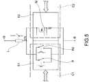
- Figure 5 illustrates a further embodiment of the system for detecting an abnormal gait condition of a bogie of a railway vehicle in the case wherein the load L is disposed between a first reference potential B+ and a first common node CN between the first electronic control means E1 and the second electronic control means E2. Consequently, the first electronic control means E1 and the second electronic control means E2 are disposed parallel to each other.
- the first and second electronic control means E1, E2 are in a normally open condition and are brought into a closed condition when the power is supplied to the system for detecting an abnormal gait condition of a bogie of a railway vehicle 1. Therefore, if a single fault concerns a component of only one of the first and second control chains C1, C2 of the system for the detection of an abnormal gait condition of a bogie of a railway vehicle, the alarm is not generated.
- both of the two control chains C1, C2 it is necessary for both of the two control chains C1, C2 to detect an abnormal gait condition of a bogie of the railway vehicle to stop powering the load L through the first or second electronic control means E1, E2 and effectively send an alarm signal.
- This embodiment makes it possible to maximize availability of the train by limiting false detections.
- the sensor means S1, S2 may both be at least one accelerometric sensor and a gyroscopic sensor.
- the first control unit U1 and the second control unit U2 each include a “different" microprocessor from each other.
- the term “different” indicates the fact that two different components are not only two distinct elements, but also have different structural features.
- said different microprocessors are microprocessors having internal structures different from each other and/or that use different technologies, and said computer programs SW1, SW2 have different codes. In this way, the occurrence of a hardware or software malfunction of both control units U1 and U2, due to the same design and/or manufacturing defect, is excluded.
- the first electronic control units E1 comprise at least one relay device R and the second electronic control units E2 include at least one MOS device M, or vice versa.
- a second relay device R2 may be provided.
- the two relay devices R, R2 may be used alternately to reduce the overheating. In any case, for the purpose of signaling an abnormal gait condition, it is sufficient to use only one relay device R.
- the abnormal gait condition is a condition of derailment of the railway vehicle 1.
- the abnormal gait condition is a condition of instability of the railway vehicle.
- the abnormal gait condition may be either a derailment condition or an instability condition of the railway vehicle.
- the system for detecting an abnormal gait condition of a railway vehicle 1 by means of the first computer program SW1, the second computer program SW2 and the data detected by the first and second sensor means S1, S2, may detect and distinguish between a derailment condition and an instability condition and generate respective alarm signals.
- the load L may be continuously de-energized and, in the event of detection of an instability condition, the load L may be de-energized in a non-continuous way, with a predetermined signaling frequency.
- the system for detecting a derailment 1 may further comprise a CAN network for sending or receiving system signals for detecting an instability condition, and, in the event of detection of a derailment condition, the load L may be de-energized continuously.
- a respective instability alarm signal may be sent via said CAN network for signaling to an operator, regardless of the load L.
- the first control chain C1 and the second control chain C2 are installed on at least one electronic board 80.
- the at least one electronic board 80 is contained in an enclosure 10.
- the enclosure may be made of metal or plastic material.
- An end 12 of a cable 14 is firmly coupled to the enclosure 10.
- the cable is used to send or receive system signals for the derailment detection 1.
- a connector 18 is installed, to which, for example, a corresponding connector of a cable connected to the load L may be connected.
- the cable 14 is preferably used for supplying power to the system and for transporting the signals of the system's CAN network, which may be used for communications from and supplied by the system for detecting abnormal gait 1.
- the system for detecting an abnormal gait condition of a railway vehicle 1 is installed preferably, but not necessarily, on a frame of a bogie 20 of the railway vehicle.
- the enclosure 10 further comprises a cover 20, which may be removed in order to access the circuitry of the system for detecting an abnormal gait condition of a railway vehicle 1 for maintenance or installation purposes.
- the system for detecting an abnormal gait condition of a railway vehicle may comprise at least one low-pass filter.
- the enclosure 10 may contain therein a resin 84 in which the at least one electronic board 80 is immersed.
- Such resin acts as a low-pass filter within the system.
- the at least one electronic board 80 is in no way fixed to the enclosure 10 in order to avoid transmitting the vibrations to which the enclosure 10 is subjected with a frequency higher than those of interest to the electronic board 80. In this way, the values acquired by the first and second sensor means S1, S2 will not be negatively affected by such vibrations.
- a dedicated frame is used to hold the electronic part in position during the casting of the resin 84, and subsequently the resin is cast into the enclosure 10 until the electronic board 80 is covered to the desired level.
- the electronic part will therefore not be rigidly fixed to any mechanical part.
- the resin must be selected for the appropriate hardness for the application in order to dampen the frequencies not of interest and avoid low frequency resonances.
- the floating encapsulation guarantees shock and vibration protection; in effect, the resin mechanically isolates the electronic part from the mechanical part on which it will be installed and acts as a damper for vibrations and shocks.
- the resin allows the use of less expensive accelerometers, such as MEMS accelerometric sensors. Less expensive accelerometers do not allow filters to be added to limit the band between the sensing element and the analogue digital conversion part. In the absence of resin, the use of such components is limited to environments not subject to vibrations in relatively high frequencies due to the problems of aliasing and saturation of the sensitive part.
- the resin also allows lower sampling frequencies to be used; in effect, the frequency to be used is at least twice the maximum frequency of the measured signal.
- the first sensor means S1 or the second sensor means S2 in a further embodiment of the system, may comprise at least one MEMS accelerometric sensor.
- the concepts described herein concerning the resin and the floating encapsulation may be applied to any detection system and not only to the system for detecting an abnormal gait condition of a railway vehicle having the features described above.
- the invention further comprises a method for detecting an abnormal gait condition of a railway vehicle.
- the method for detecting an abnormal gait condition of a railway vehicle comprises the steps of acquiring first detection data of the attitude and/or movement of the railway vehicle by means of first sensor means S1 of a first control chain C1, transmitting the first detection data from the first sensor means S1 to a first control unit U1 of the first control chain C1, executing the first computer program SW1 for checking an abnormal gait of the railway vehicle in the first control unit U1 of the first control chain C1, and controlling, by means of the first control unit U1, the first electronic control means E1 of the first control chain C1, as a function of the decisions of the first computer program SW1 for checking an abnormal gait of the railway vehicle, to supply or not supply power to a load L.
- the method further comprises the steps of acquiring second detection data of the attitude and/or movement of the railway vehicle by means of second sensor means S2 of a second control chain C2, different from said first sensor means S1, transmitting the second detection data from the second sensor means S2 to a second control unit U2 of the second control chain C2, different from said first control unit U1, executing the second computer program SW2 for checking the abnormal gait of the railway vehicle, different from said first computer program SW1 for checking an abnormal gait of the railway vehicle, in the second control unit U2 of the second control chain C2, and controlling, by means of the second control unit U2, second electronic control means E2 of the second control chain C2, different from said first electronic control means E1, according to the decisions of the second computer program SW2 for checking an abnormal gait of the railway vehicle, to supply or not supply power to the load L.
- the program SW1 acquires the data measured by the first sensor means S1, respectively the data measured by a first accelerometric sensor and a second gyroscopic sensor. Such data are acquired at a suitable frequency (for example 2000 Hz), obtaining the instantaneous acceleration values in the three axes x, y, z of the bogie and the angular velocity of a wheel.
- a suitable frequency for example 2000 Hz
- x coincides with the axis longitudinal to the rail
- y coincides with the axis transverse to the rail
- z coincides with the vertical axis with respect to the rail.
- the first and the second computer program for checking a derailment SW1, SW2 may exploit different detection criteria, for example, SW1 exploits detection criteria in the time domain and SW2 exploits detection criteria in the frequency domain.
- an analysis of the bogie's position in space may be carried out, obtaining the instantaneous position of the bogie through successive integrations in time of linear and angular accelerations relative to the three axes.
- Such integrations must be performed within a moving time window of limited duration in order to avoid drift of the integrators.
- Such integrations will provide information relating to possible jumps of vertical position or sudden rotation of the bogie, indicating a derailment even at very low speeds, where the vertical accelerations may not give immediate information on a derailment that has occurred.
- an illustrative embodiment of the method for detecting an abnormal gait condition of a railway vehicle is provided.
- the detection of an abnormal gait condition of a railway vehicle bases the detection of an abnormal gait condition of a bogie of the railway vehicle, in particular of the instability and/or derailment of the bogie, on three criteria:
- Detection of the derailment and/or bogie instability may combine the three criteria set out above. Each criterion contributes with different weights to detection. For example, if a predetermined threshold is exceeded, a derailment alarm signal is generated; if, on the other hand, a second predetermined lower threshold than said first threshold is surpassed, an instability signal is generated.
- comparison frequency masks may be used to detect abnormal gait conditions.
Landscapes
- Engineering & Computer Science (AREA)
- Mechanical Engineering (AREA)
- Train Traffic Observation, Control, And Security (AREA)
- Electric Propulsion And Braking For Vehicles (AREA)
Claims (17)
- System zum Detektieren eines anomalen Gangzustands eines Schienenfahrzeugs (1), mit einer ersten Steuerungskette (C1) und einer zweiten Steuerungskette (C2), die mit einem digitalen Ausgang (O) verbunden sind, der so angeordnet ist, dass er eine Last (L) abhängig von der Detektion eines anomalen Gangzustands des Schienenfahrzeugs speist oder nicht speist; welche erste Steuerungskette (C1) aufweist:- erste Sensormittel (S1), die so angeordnet sind, dass sie erste Detektionsdaten der Bewegung des Schienenfahrzeugs detektieren; und- eine erste Steuerungseinheit (U1), die so angeordnet ist, dass sie besagte erste Detektionsdaten der Bewegung des Schienenfahrzeugs von besagten ersten Sensormitteln (S1) empfängt, dass sie ein erstes Computerprogramm (SW1) zum Überprüfen eines anomalen Gangs ausführt, und dass sie erste elektronische Steuerungsmittel (E1) zum Speisen oder Nichtspeisen der Last (L) steuert;und welche zweite Steuerungskette (C2) aufweist:- zweite Sensormittel (S2), die so angeordnet sind, dass sie zweite Detektionsdaten der Bewegung des Schienenfahrzeugs detektieren;welche besagten zweiten Sensormittel (S2) von besagten ersten Sensormitteln (S1) verschieden sind;
welches System zum Detektieren eines anomalen Gangzustands eines Schienenfahrzeugs (1) dadurch gekennzeichnet ist, dass die zweite Steuerungskette (C2) ferner aufweist:- eine zweite Steuerungseinheit (U2), die so angeordnet ist, dass sie besagte zweite Detektionsdaten der Bewegung des Schienenfahrzeugs von den zweiten Sensormitteln (S2) empfängt, dass sie ein zweites Computerprogramm (SW2) zum Überprüfen eines anomalen Gangs ausführt, und dass sie zweite elektronische Steuerungsmittel (E2) zum Speisen oder Nichtspeisen der Last (L) steuert;welche besagte zweite Steuerungseinheit (U2) von besagter ersten Steuerungseinheit (U1) verschieden ist, welches besagte zweite Computerprogramm (SW2) von besagtem ersten Computerprogramm (SW1) verschieden ist und welche besagten zweiten elektronischen Steuerungsmittel (E2) von besagten ersten elektronischen Steuerungsmitteln (E1) verschieden sind. - System zum Detektieren eines anomalen Gangzustands eines Schienenfahrzeugs (1) nach Anspruch 1, bei dem der anomale Gangzustand ein Entgleisungszustand des Schienenfahrzeugs (1) ist.
- System zum Detektieren eines anomalen Gangzustands eines Schienenfahrzeugs (1) nach Anspruch 1, bei dem der anomale Gangzustand ein Instabilitätszustand des Schienenfahrzeugs ist.
- System zum Detektieren eines anomalen Gangzustands eines Schienenfahrzeugs (1) nach Anspruch 1, bei dem der anomale Gangzustand ein Zustand einer Entgleisung des Schienenfahrzeugs (1) oder ein Instabilitätszustand des Schienenfahrzeugs ist.
- System zum Detektieren eines anomalen Gangzustands eines Schienenfahrzeugs (1) nach Anspruch 3 oder 4, mit einem CAN-Netzwerk zum Senden oder Empfangen von Signalen des Systems zum Detektieren eines anomalen Gangzustands eines Schienenfahrzeugs (1); bei dem das erste und das zweite Computerprogramm (SW1, SW2) imstande sind, einen Zustand einer Instabilität zu bestimmen und ein jeweiliges Alarmsignal, das über besagtes CAN-Netzwerk gesendet wird, zu erzeugen.
- System zum Detektieren eines anomalen Gangzustands eines Schienenfahrzeugs (1) nach einem der vorhergehenden Ansprüche, bei dem die Last (L) zwischen einem ersten Knoten (N1) der ersten elektronischen Steuerungsmittel (E1) und einem ersten Knoten (N2) der zweiten elektronischen Steuerungsmittel (E2) angeordnet ist.
- System zum Detektieren eines anomalen Gangzustands eines Schienenfahrzeugs (1) nach einem der Ansprüche 1 bis 5, bei dem die Last (L) zwischen einem ersten Knoten (N1) der ersten elektronischen Steuerungsmittel (E1) und einem ersten Referenzpotenzial (B+) oder zwischen einem ersten Knoten (N2) der zweiten elektronischen Steuerungsmittel und einem zweiten Referenzpotenzial (B-) angeordnet ist.
- System zum Detektieren eines anomalen Gangzustands eines Schienenfahrzeugs (1) nach einem der Ansprüche 1 bis 5, bei dem die Last (L) zwischen einem ersten Referenzpotenzial (B+) und einem ersten gemeinsamen Knoten (CN) der ersten elektronischen Steuerungsmittel (E1) und der zweiten elektronischen Steuerungsmittel (E2) angeordnet ist.
- System zum Detektieren eines anomalen Gangzustands eines Schienenfahrzeugs (1) nach einem der vorhergehenden Ansprüche, bei dem die ersten Sensormittel (S1) zumindest ein Kreiselsensor und ein Beschleunigungssensor sind, und die zweiten Sensormittel (S2) zumindest ein Kreiselsensor und ein Beschleunigungssensor sind.
- System zum Detektieren eines anomalen Gangzustands eines Schienenfahrzeugs (1) nach einem der vorhergehenden Ansprüche, bei dem die erste Steuerungseinheit (U1) und die zweite Steuerungseinheit (U2) jeweils mindestens einen zwischen ihnen verschiedenen Mikroprozessor aufweisen.
- System zum Detektieren eines anomalen Gangzustands eines Schienenfahrzeugs (1) nach einem der vorhergehenden Ansprüche, bei dem die ersten elektronischen Steuerungseinheiten (E1) mindestens eine Relaisvorrichtung (R) aufweisen und die zweiten elektronischen Steuerungseinheiten (E2) mindestens eine MOS-Vorrichtung (M) aufweisen.
- System zum Detektieren eines anomalen Gangzustands eines Schienenfahrzeugs (1) nach einem der vorhergehenden Ansprüche, bei dem die Last (L), die mit dem digitalen Ausgang (O) verbunden ist, ein Signalisierungsmittel ist, das dazu angepasst ist, einen Bediener des Schienenfahrzeugs (VR) über das Auftreten eines anomalen Gangzustands des Schienenfahrzeugs visuell und/oder akustisch zu alarmieren, oder die Last (L) ein Bremssystem des Schienenfahrzeugs ist.
- System zum Detektieren eines anomalen Gangzustands eines Schienenfahrzeugs (1) nach einem der vorhergehenden Ansprüche, bei dem die erste Steuerungskette (C1) und die zweite Steuerungskette (C2) auf mindestens einer Elektronikplatine (80), die in einem Gehäuse (10) enthalten ist, installiert sind.
- System zum Detektieren eines anomalen Gangzustands eines Schienenfahrzeugs (1) nach Anspruch 13, bei dem das Gehäuse (10) ein Harz (84) enthält, das so angeordnet ist, dass es eine Tiefpassfilterfunktion durchführt, und in das die mindestens eine Elektronikplatine (80) eingetaucht ist; welche mindestens eine Elektronikplatine (80) nicht in irgendeiner Weise an dem Gehäuse (10) befestigt ist.
- System zum Detektieren eines anomalen Gangzustands eines Schienenfahrzeugs (1) nach einem der vorhergehenden Ansprüche, bei dem besagtes System zum Detektieren eines anomalen Gangzustands eines Schienenfahrzeugs (1) auf einem Rahmen (20) eines Fahrwerks des Schienenfahrzeugs installiert ist.
- Verfahren zum Detektieren eines anomalen Gangzustands eines Schienenfahrzeugs (1) mit den Schritten:- Beschaffen erster Detektionsdaten der Bewegung des Schienenfahrzeugs mittels erster Sensormittel (S1) einer ersten Steuerungskette (C1);- Übertragen der ersten Detektionsdaten von den ersten Sensormitteln (S1) an eine erste Steuerungseinheit (U1) der ersten Steuerungskette (C1);- Ausführen eines ersten Computerprogramms (SW1) zum Überprüfen eines anomalen Gangzustands des Schienenfahrzeugs in einer ersten Steuerungseinheit (U1) der ersten Steuerungskette (C1);- Steuern, mittels der ersten Steuerungseinheit (U1), erster elektronischer Steuerungsmittel (E1) der ersten Steuerungskette (C1) als eine Funktion der Entscheidungen des ersten Computerprogramms (SW1) zum Überprüfen eines anomalen Gangzustands des Schienenfahrzeugs, zum Speisen oder Nichtspeisen einer Last (L);- Beschaffen zweiter Detektionsdaten der Bewegung des Schienenfahrzeugs mittels zweiter Sensormittel (S2) einer zweiten Steuerungskette (C2), die von besagten ersten Sensormitteln (S1) verschieden sind;- Übertragen der zweiten Detektionsdaten von den zweiten Sensormitteln (S2) an eine zweite Steuerungseinheit (U2) der zweiten Steuerungskette (C2), die von besagter ersten Steuerungseinheit (U1) verschieden ist;- Ausführen eines zweiten Computerprogramms (SW2) zum Überprüfen eines anomalen Gangzustands des Schienenfahrzeugs, das von besagtem ersten Computerprogramm (SW1) zum Überprüfen eines anomalen Gangzustands des Schienenfahrzeugs verschieden ist, in der zweiten Steuerungseinheit (U2) der zweiten Steuerungskette (C2);- Steuern, mittels der zweiten Steuerungseinheit (U2), zweiter elektronischer Steuerungsmittel (E2) der zweiten Steuerungskette (C2), die von besagten ersten elektronischen Steuerungsmitteln (E1) verschieden sind, als eine Funktion der Entscheidungen des zweiten Computerprogramms (SW2) zum Überprüfen eines anomalen Gangzustands des Schienenfahrzeugs, zum Speisen oder Nichtspeisen der Last (L).
- Verfahren zum Detektieren eines anomalen Gangzustands eines Schienenfahrzeugs (1) nach Anspruch 16, bei dem das erste Computerprogramm (SW1) und das zweite Computerprogramm (SW2) zum Überprüfen eines anomalen Gangzustands des Schienenfahrzeugs, respektive, eines die Zeitdomänendetektionskriterien und das andere die Frequenzdomänendetektionskriterien verwenden.
Applications Claiming Priority (2)
| Application Number | Priority Date | Filing Date | Title |
|---|---|---|---|
| IT102017000050006A IT201700050006A1 (it) | 2017-05-09 | 2017-05-09 | Sistema e procedimento per il rilevamento di una condizione di andatura anomala di un carrello di un veicolo ferroviario. |
| PCT/IB2018/053223 WO2018207114A1 (en) | 2017-05-09 | 2018-05-09 | System and method for detecting an abnormal gait condition of a railway vehicle |
Publications (2)
| Publication Number | Publication Date |
|---|---|
| EP3621866A1 EP3621866A1 (de) | 2020-03-18 |
| EP3621866B1 true EP3621866B1 (de) | 2021-07-07 |
Family
ID=59974746
Family Applications (1)
| Application Number | Title | Priority Date | Filing Date |
|---|---|---|---|
| EP18728963.2A Active EP3621866B1 (de) | 2017-05-09 | 2018-05-09 | System und verfahren zur detektion eines anomalen gangzustands eines schienenfahrzeugs |
Country Status (7)
| Country | Link |
|---|---|
| US (1) | US11529978B2 (de) |
| EP (1) | EP3621866B1 (de) |
| JP (1) | JP7121753B2 (de) |
| ES (1) | ES2887264T3 (de) |
| HU (1) | HUE055520T2 (de) |
| IT (1) | IT201700050006A1 (de) |
| WO (1) | WO2018207114A1 (de) |
Families Citing this family (2)
| Publication number | Priority date | Publication date | Assignee | Title |
|---|---|---|---|---|
| US20230058093A1 (en) * | 2017-05-09 | 2023-02-23 | Faiveley Transport Italia S.P.A. | Vehicle control system |
| JP7242518B2 (ja) * | 2019-12-16 | 2023-03-20 | 株式会社東芝 | 非破壊検査方法及び非破壊検査システム |
Citations (2)
| Publication number | Priority date | Publication date | Assignee | Title |
|---|---|---|---|---|
| EP1236633A2 (de) * | 2001-02-28 | 2002-09-04 | Siemens SGP Verkehrstechnik GmbH | Verfahren zur allgemeinen Entgleisungsdetektion |
| EP2602168A1 (de) * | 2011-12-07 | 2013-06-12 | Railway Metrics and Dynamics Sweden AB | Verfahren und System zur Erkennung und Analyse von Betriebsproblemen bei Eisenbahndrehgestellen |
Family Cites Families (15)
| Publication number | Priority date | Publication date | Assignee | Title |
|---|---|---|---|---|
| DE29901917U1 (de) * | 1999-02-04 | 1999-07-22 | Schultheiß, Dominik, 95445 Bayreuth | Radüberwachungssystem |
| DE10062602B4 (de) * | 2000-12-12 | 2006-02-23 | Db Fernverkehr Ag | Verfahren und Vorrichtung zum Überwachen des Fahrverhaltens von Schienenfahrzeugen und zur Diagnose von Komponenten von Schienenfahrzeugen |
| US10308265B2 (en) * | 2006-03-20 | 2019-06-04 | Ge Global Sourcing Llc | Vehicle control system and method |
| US7826946B2 (en) * | 2002-09-05 | 2010-11-02 | Bombardier Transportation Gmbh | Method and device for monitoring the state of vehicle chassis |
| EP2165912B1 (de) | 2008-09-19 | 2012-04-25 | Bombardier Transportation GmbH | Instabilitätsüberwachungsvorrichtung und -system, insbesondere für ein Schienenfahrzeug |
| DE102009020428A1 (de) * | 2008-11-19 | 2010-05-20 | Eureka Navigation Solutions Ag | Vorrichtung und Verfahren für ein Schienenfahrzeug |
| JP5432818B2 (ja) | 2010-05-24 | 2014-03-05 | 株式会社日立製作所 | 鉄道車両の状態監視装置及び状態監視方法、並びに鉄道車両 |
| KR20120014092A (ko) | 2010-08-08 | 2012-02-16 | 명관 이 | 열차 탈선 검출 시스템 및 그 제어방법 |
| JP5812595B2 (ja) | 2010-11-02 | 2015-11-17 | 曙ブレーキ工業株式会社 | 鉄道車両用異常診断システム |
| DE102012217721A1 (de) * | 2012-09-28 | 2014-04-03 | Siemens Aktiengesellschaft | Vorrichtung für ein Schienenfahrzeug |
| DE102012217830A1 (de) * | 2012-09-28 | 2014-04-03 | Siemens Aktiengesellschaft | Vorrichtung für ein Schienenfahrzeug |
| JP6128594B2 (ja) | 2013-05-29 | 2017-05-17 | 曙ブレーキ工業株式会社 | 脱線予兆検知システム、制御装置、脱線予兆検知方法、及び脱線予兆検知プログラム |
| US10137915B2 (en) * | 2013-12-24 | 2018-11-27 | Amsted Rail Company, Inc. | System and method for detecting operational anomalies in train consists and railcars |
| US9434397B2 (en) * | 2014-08-05 | 2016-09-06 | Panasec Corporation | Positive train control system and apparatus therefor |
| JP6435203B2 (ja) | 2015-01-22 | 2018-12-05 | 株式会社総合車両製作所 | 脱線検知装置及び脱線検知方法 |
-
2017
- 2017-05-09 IT IT102017000050006A patent/IT201700050006A1/it unknown
-
2018
- 2018-05-09 HU HUE18728963A patent/HUE055520T2/hu unknown
- 2018-05-09 WO PCT/IB2018/053223 patent/WO2018207114A1/en not_active Ceased
- 2018-05-09 EP EP18728963.2A patent/EP3621866B1/de active Active
- 2018-05-09 JP JP2019561174A patent/JP7121753B2/ja active Active
- 2018-05-09 ES ES18728963T patent/ES2887264T3/es active Active
- 2018-05-09 US US16/611,896 patent/US11529978B2/en active Active
Patent Citations (2)
| Publication number | Priority date | Publication date | Assignee | Title |
|---|---|---|---|---|
| EP1236633A2 (de) * | 2001-02-28 | 2002-09-04 | Siemens SGP Verkehrstechnik GmbH | Verfahren zur allgemeinen Entgleisungsdetektion |
| EP2602168A1 (de) * | 2011-12-07 | 2013-06-12 | Railway Metrics and Dynamics Sweden AB | Verfahren und System zur Erkennung und Analyse von Betriebsproblemen bei Eisenbahndrehgestellen |
Also Published As
| Publication number | Publication date |
|---|---|
| US20200290656A1 (en) | 2020-09-17 |
| WO2018207114A1 (en) | 2018-11-15 |
| US11529978B2 (en) | 2022-12-20 |
| JP2020519519A (ja) | 2020-07-02 |
| EP3621866A1 (de) | 2020-03-18 |
| HUE055520T2 (hu) | 2021-11-29 |
| ES2887264T3 (es) | 2021-12-22 |
| IT201700050006A1 (it) | 2018-11-09 |
| JP7121753B2 (ja) | 2022-08-18 |
Similar Documents
| Publication | Publication Date | Title |
|---|---|---|
| EP2602168B1 (de) | Verfahren und System zur Erkennung und Analyse von Betriebsproblemen bei Eisenbahndrehgestellen | |
| AU2019396832B2 (en) | Transport and rail infrastructure monitoring system | |
| JP4298433B2 (ja) | 鉄道車両の異常検知装置 | |
| JP5812595B2 (ja) | 鉄道車両用異常診断システム | |
| CN112424840A (zh) | 用于监测车辆的驾驶模式相关状态的传感器装置和方法 | |
| CN108139426B (zh) | 用于识别加速度传感器的故障的方法和测量系统 | |
| JP2012078213A (ja) | 鉄道車両の状態監視装置及び状態監視方法、並びに鉄道車両 | |
| JP6302315B2 (ja) | 状態監視装置 | |
| US20070203621A1 (en) | Rail track evaluation system | |
| JP2012502837A (ja) | 特に鉄道車両用の不安定モニタリングデバイスおよびシステム | |
| JP7146653B2 (ja) | 鉄道車両における列車制御システム及び地震検知システム | |
| US11529978B2 (en) | System and method for detecting an abnormal gait condition of a railway vehicle | |
| CN112912297A (zh) | 用于检测轨道车辆的脱轨状态的方法和装置 | |
| JP4845426B2 (ja) | 車体振動制御装置及び車体振動制御方法 | |
| ITTO20101061A1 (it) | Procedimento per il riconoscimento di brusche manovre di guida di un veicolo e sistema di sorveglianza delle condizioni di marcia di un veicolo | |
| JP2018054567A (ja) | 鉄道車両の異常検知方法 | |
| US20160207612A1 (en) | Method for managing the braking of an aircraft with speed measurement close to the braked wheels | |
| US20230058093A1 (en) | Vehicle control system | |
| JP7339351B2 (ja) | 鉄道車両の制動動作の検出方法及び鉄道車両の緊急制動方法 | |
| CN223686579U (zh) | 一种预脱轨检测系统 | |
| AU2020200401A1 (en) | Methods and devices for monitoring train integrity | |
| JP2025091868A (ja) | 鉄道車両の脱線検知装置 | |
| EP1400427A1 (de) | Verfahren und Gerät für die Entgleisungsdetektion der Schienenfahrzeuge | |
| CN119975458A (zh) | 一种预脱轨检测方法及系统 | |
| JP2010105493A (ja) | 衝突判定装置、衝突判定方法および車両ならびにプログラム |
Legal Events
| Date | Code | Title | Description |
|---|---|---|---|
| STAA | Information on the status of an ep patent application or granted ep patent |
Free format text: STATUS: UNKNOWN |
|
| STAA | Information on the status of an ep patent application or granted ep patent |
Free format text: STATUS: THE INTERNATIONAL PUBLICATION HAS BEEN MADE |
|
| PUAI | Public reference made under article 153(3) epc to a published international application that has entered the european phase |
Free format text: ORIGINAL CODE: 0009012 |
|
| STAA | Information on the status of an ep patent application or granted ep patent |
Free format text: STATUS: REQUEST FOR EXAMINATION WAS MADE |
|
| 17P | Request for examination filed |
Effective date: 20191128 |
|
| AK | Designated contracting states |
Kind code of ref document: A1 Designated state(s): AL AT BE BG CH CY CZ DE DK EE ES FI FR GB GR HR HU IE IS IT LI LT LU LV MC MK MT NL NO PL PT RO RS SE SI SK SM TR |
|
| AX | Request for extension of the european patent |
Extension state: BA ME |
|
| DAV | Request for validation of the european patent (deleted) | ||
| DAX | Request for extension of the european patent (deleted) | ||
| GRAP | Despatch of communication of intention to grant a patent |
Free format text: ORIGINAL CODE: EPIDOSNIGR1 |
|
| STAA | Information on the status of an ep patent application or granted ep patent |
Free format text: STATUS: GRANT OF PATENT IS INTENDED |
|
| INTG | Intention to grant announced |
Effective date: 20201218 |
|
| GRAS | Grant fee paid |
Free format text: ORIGINAL CODE: EPIDOSNIGR3 |
|
| GRAA | (expected) grant |
Free format text: ORIGINAL CODE: 0009210 |
|
| STAA | Information on the status of an ep patent application or granted ep patent |
Free format text: STATUS: THE PATENT HAS BEEN GRANTED |
|
| AK | Designated contracting states |
Kind code of ref document: B1 Designated state(s): AL AT BE BG CH CY CZ DE DK EE ES FI FR GB GR HR HU IE IS IT LI LT LU LV MC MK MT NL NO PL PT RO RS SE SI SK SM TR |
|
| REG | Reference to a national code |
Ref country code: GB Ref legal event code: FG4D |
|
| REG | Reference to a national code |
Ref country code: AT Ref legal event code: REF Ref document number: 1408313 Country of ref document: AT Kind code of ref document: T Effective date: 20210715 |
|
| REG | Reference to a national code |
Ref country code: DE Ref legal event code: R096 Ref document number: 602018019749 Country of ref document: DE |
|
| REG | Reference to a national code |
Ref country code: IE Ref legal event code: FG4D |
|
| REG | Reference to a national code |
Ref country code: LT Ref legal event code: MG9D |
|
| REG | Reference to a national code |
Ref country code: NL Ref legal event code: MP Effective date: 20210707 |
|
| REG | Reference to a national code |
Ref country code: HU Ref legal event code: AG4A Ref document number: E055520 Country of ref document: HU |
|
| REG | Reference to a national code |
Ref country code: AT Ref legal event code: MK05 Ref document number: 1408313 Country of ref document: AT Kind code of ref document: T Effective date: 20210707 |
|
| REG | Reference to a national code |
Ref country code: ES Ref legal event code: FG2A Ref document number: 2887264 Country of ref document: ES Kind code of ref document: T3 Effective date: 20211222 |
|
| PG25 | Lapsed in a contracting state [announced via postgrant information from national office to epo] |
Ref country code: AT Free format text: LAPSE BECAUSE OF FAILURE TO SUBMIT A TRANSLATION OF THE DESCRIPTION OR TO PAY THE FEE WITHIN THE PRESCRIBED TIME-LIMIT Effective date: 20210707 Ref country code: BG Free format text: LAPSE BECAUSE OF FAILURE TO SUBMIT A TRANSLATION OF THE DESCRIPTION OR TO PAY THE FEE WITHIN THE PRESCRIBED TIME-LIMIT Effective date: 20211007 Ref country code: LT Free format text: LAPSE BECAUSE OF FAILURE TO SUBMIT A TRANSLATION OF THE DESCRIPTION OR TO PAY THE FEE WITHIN THE PRESCRIBED TIME-LIMIT Effective date: 20210707 Ref country code: PT Free format text: LAPSE BECAUSE OF FAILURE TO SUBMIT A TRANSLATION OF THE DESCRIPTION OR TO PAY THE FEE WITHIN THE PRESCRIBED TIME-LIMIT Effective date: 20211108 Ref country code: NL Free format text: LAPSE BECAUSE OF FAILURE TO SUBMIT A TRANSLATION OF THE DESCRIPTION OR TO PAY THE FEE WITHIN THE PRESCRIBED TIME-LIMIT Effective date: 20210707 Ref country code: NO Free format text: LAPSE BECAUSE OF FAILURE TO SUBMIT A TRANSLATION OF THE DESCRIPTION OR TO PAY THE FEE WITHIN THE PRESCRIBED TIME-LIMIT Effective date: 20211007 Ref country code: RS Free format text: LAPSE BECAUSE OF FAILURE TO SUBMIT A TRANSLATION OF THE DESCRIPTION OR TO PAY THE FEE WITHIN THE PRESCRIBED TIME-LIMIT Effective date: 20210707 Ref country code: SE Free format text: LAPSE BECAUSE OF FAILURE TO SUBMIT A TRANSLATION OF THE DESCRIPTION OR TO PAY THE FEE WITHIN THE PRESCRIBED TIME-LIMIT Effective date: 20210707 Ref country code: FI Free format text: LAPSE BECAUSE OF FAILURE TO SUBMIT A TRANSLATION OF THE DESCRIPTION OR TO PAY THE FEE WITHIN THE PRESCRIBED TIME-LIMIT Effective date: 20210707 Ref country code: HR Free format text: LAPSE BECAUSE OF FAILURE TO SUBMIT A TRANSLATION OF THE DESCRIPTION OR TO PAY THE FEE WITHIN THE PRESCRIBED TIME-LIMIT Effective date: 20210707 |
|
| PG25 | Lapsed in a contracting state [announced via postgrant information from national office to epo] |
Ref country code: PL Free format text: LAPSE BECAUSE OF FAILURE TO SUBMIT A TRANSLATION OF THE DESCRIPTION OR TO PAY THE FEE WITHIN THE PRESCRIBED TIME-LIMIT Effective date: 20210707 Ref country code: LV Free format text: LAPSE BECAUSE OF FAILURE TO SUBMIT A TRANSLATION OF THE DESCRIPTION OR TO PAY THE FEE WITHIN THE PRESCRIBED TIME-LIMIT Effective date: 20210707 Ref country code: GR Free format text: LAPSE BECAUSE OF FAILURE TO SUBMIT A TRANSLATION OF THE DESCRIPTION OR TO PAY THE FEE WITHIN THE PRESCRIBED TIME-LIMIT Effective date: 20211008 |
|
| REG | Reference to a national code |
Ref country code: DE Ref legal event code: R097 Ref document number: 602018019749 Country of ref document: DE |
|
| PG25 | Lapsed in a contracting state [announced via postgrant information from national office to epo] |
Ref country code: DK Free format text: LAPSE BECAUSE OF FAILURE TO SUBMIT A TRANSLATION OF THE DESCRIPTION OR TO PAY THE FEE WITHIN THE PRESCRIBED TIME-LIMIT Effective date: 20210707 |
|
| PLBE | No opposition filed within time limit |
Free format text: ORIGINAL CODE: 0009261 |
|
| STAA | Information on the status of an ep patent application or granted ep patent |
Free format text: STATUS: NO OPPOSITION FILED WITHIN TIME LIMIT |
|
| PG25 | Lapsed in a contracting state [announced via postgrant information from national office to epo] |
Ref country code: SM Free format text: LAPSE BECAUSE OF FAILURE TO SUBMIT A TRANSLATION OF THE DESCRIPTION OR TO PAY THE FEE WITHIN THE PRESCRIBED TIME-LIMIT Effective date: 20210707 Ref country code: SK Free format text: LAPSE BECAUSE OF FAILURE TO SUBMIT A TRANSLATION OF THE DESCRIPTION OR TO PAY THE FEE WITHIN THE PRESCRIBED TIME-LIMIT Effective date: 20210707 Ref country code: RO Free format text: LAPSE BECAUSE OF FAILURE TO SUBMIT A TRANSLATION OF THE DESCRIPTION OR TO PAY THE FEE WITHIN THE PRESCRIBED TIME-LIMIT Effective date: 20210707 Ref country code: EE Free format text: LAPSE BECAUSE OF FAILURE TO SUBMIT A TRANSLATION OF THE DESCRIPTION OR TO PAY THE FEE WITHIN THE PRESCRIBED TIME-LIMIT Effective date: 20210707 Ref country code: CZ Free format text: LAPSE BECAUSE OF FAILURE TO SUBMIT A TRANSLATION OF THE DESCRIPTION OR TO PAY THE FEE WITHIN THE PRESCRIBED TIME-LIMIT Effective date: 20210707 Ref country code: AL Free format text: LAPSE BECAUSE OF FAILURE TO SUBMIT A TRANSLATION OF THE DESCRIPTION OR TO PAY THE FEE WITHIN THE PRESCRIBED TIME-LIMIT Effective date: 20210707 |
|
| 26N | No opposition filed |
Effective date: 20220408 |
|
| REG | Reference to a national code |
Ref country code: CH Ref legal event code: PL |
|
| REG | Reference to a national code |
Ref country code: BE Ref legal event code: MM Effective date: 20220531 |
|
| PG25 | Lapsed in a contracting state [announced via postgrant information from national office to epo] |
Ref country code: MC Free format text: LAPSE BECAUSE OF FAILURE TO SUBMIT A TRANSLATION OF THE DESCRIPTION OR TO PAY THE FEE WITHIN THE PRESCRIBED TIME-LIMIT Effective date: 20210707 Ref country code: LU Free format text: LAPSE BECAUSE OF NON-PAYMENT OF DUE FEES Effective date: 20220509 Ref country code: LI Free format text: LAPSE BECAUSE OF NON-PAYMENT OF DUE FEES Effective date: 20220531 Ref country code: CH Free format text: LAPSE BECAUSE OF NON-PAYMENT OF DUE FEES Effective date: 20220531 |
|
| PG25 | Lapsed in a contracting state [announced via postgrant information from national office to epo] |
Ref country code: IE Free format text: LAPSE BECAUSE OF NON-PAYMENT OF DUE FEES Effective date: 20220509 |
|
| PG25 | Lapsed in a contracting state [announced via postgrant information from national office to epo] |
Ref country code: BE Free format text: LAPSE BECAUSE OF NON-PAYMENT OF DUE FEES Effective date: 20220531 |
|
| P01 | Opt-out of the competence of the unified patent court (upc) registered |
Effective date: 20230530 |
|
| PG25 | Lapsed in a contracting state [announced via postgrant information from national office to epo] |
Ref country code: MK Free format text: LAPSE BECAUSE OF FAILURE TO SUBMIT A TRANSLATION OF THE DESCRIPTION OR TO PAY THE FEE WITHIN THE PRESCRIBED TIME-LIMIT Effective date: 20210707 Ref country code: CY Free format text: LAPSE BECAUSE OF FAILURE TO SUBMIT A TRANSLATION OF THE DESCRIPTION OR TO PAY THE FEE WITHIN THE PRESCRIBED TIME-LIMIT Effective date: 20210707 |
|
| PG25 | Lapsed in a contracting state [announced via postgrant information from national office to epo] |
Ref country code: TR Free format text: LAPSE BECAUSE OF FAILURE TO SUBMIT A TRANSLATION OF THE DESCRIPTION OR TO PAY THE FEE WITHIN THE PRESCRIBED TIME-LIMIT Effective date: 20210707 |
|
| PG25 | Lapsed in a contracting state [announced via postgrant information from national office to epo] |
Ref country code: MT Free format text: LAPSE BECAUSE OF FAILURE TO SUBMIT A TRANSLATION OF THE DESCRIPTION OR TO PAY THE FEE WITHIN THE PRESCRIBED TIME-LIMIT Effective date: 20210707 |
|
| PGFP | Annual fee paid to national office [announced via postgrant information from national office to epo] |
Ref country code: DE Payment date: 20250429 Year of fee payment: 8 |
|
| PGFP | Annual fee paid to national office [announced via postgrant information from national office to epo] |
Ref country code: GB Payment date: 20250515 Year of fee payment: 8 Ref country code: ES Payment date: 20250612 Year of fee payment: 8 |
|
| PGFP | Annual fee paid to national office [announced via postgrant information from national office to epo] |
Ref country code: HU Payment date: 20250508 Year of fee payment: 8 |
|
| PGFP | Annual fee paid to national office [announced via postgrant information from national office to epo] |
Ref country code: IT Payment date: 20250429 Year of fee payment: 8 |
|
| PGFP | Annual fee paid to national office [announced via postgrant information from national office to epo] |
Ref country code: FR Payment date: 20250515 Year of fee payment: 8 |