EP3621876B1 - Stol-flugzeug - Google Patents
Stol-flugzeug Download PDFInfo
- Publication number
- EP3621876B1 EP3621876B1 EP18801340.3A EP18801340A EP3621876B1 EP 3621876 B1 EP3621876 B1 EP 3621876B1 EP 18801340 A EP18801340 A EP 18801340A EP 3621876 B1 EP3621876 B1 EP 3621876B1
- Authority
- EP
- European Patent Office
- Prior art keywords
- landing gear
- aircraft
- landing
- strut
- control system
- Prior art date
- Legal status (The legal status is an assumption and is not a legal conclusion. Google has not performed a legal analysis and makes no representation as to the accuracy of the status listed.)
- Active
Links
Images









Classifications
-
- B—PERFORMING OPERATIONS; TRANSPORTING
- B64—AIRCRAFT; AVIATION; COSMONAUTICS
- B64C—AEROPLANES; HELICOPTERS
- B64C25/00—Alighting gear
- B64C25/02—Undercarriages
- B64C25/08—Undercarriages non-fixed, e.g. jettisonable
- B64C25/10—Undercarriages non-fixed, e.g. jettisonable retractable, foldable, or the like
- B64C25/14—Undercarriages non-fixed, e.g. jettisonable retractable, foldable, or the like fore-and-aft
-
- B—PERFORMING OPERATIONS; TRANSPORTING
- B64—AIRCRAFT; AVIATION; COSMONAUTICS
- B64C—AEROPLANES; HELICOPTERS
- B64C1/00—Fuselages; Constructional features common to fuselages, wings, stabilising surfaces or the like
- B64C1/06—Frames; Stringers; Longerons ; Fuselage sections
- B64C1/068—Fuselage sections
- B64C1/0683—Nose cones
-
- B—PERFORMING OPERATIONS; TRANSPORTING
- B64—AIRCRAFT; AVIATION; COSMONAUTICS
- B64C—AEROPLANES; HELICOPTERS
- B64C25/00—Alighting gear
- B64C25/02—Undercarriages
- B64C25/08—Undercarriages non-fixed, e.g. jettisonable
- B64C25/10—Undercarriages non-fixed, e.g. jettisonable retractable, foldable, or the like
- B64C25/18—Operating mechanisms
- B64C25/24—Operating mechanisms electric
-
- B—PERFORMING OPERATIONS; TRANSPORTING
- B64—AIRCRAFT; AVIATION; COSMONAUTICS
- B64C—AEROPLANES; HELICOPTERS
- B64C25/00—Alighting gear
- B64C25/02—Undercarriages
- B64C25/08—Undercarriages non-fixed, e.g. jettisonable
- B64C25/10—Undercarriages non-fixed, e.g. jettisonable retractable, foldable, or the like
- B64C25/18—Operating mechanisms
- B64C25/26—Control or locking systems therefor
-
- B—PERFORMING OPERATIONS; TRANSPORTING
- B64—AIRCRAFT; AVIATION; COSMONAUTICS
- B64C—AEROPLANES; HELICOPTERS
- B64C25/00—Alighting gear
- B64C25/32—Alighting gear characterised by elements which contact the ground or similar surface
- B64C25/405—Powered wheels, e.g. for taxing
-
- B—PERFORMING OPERATIONS; TRANSPORTING
- B64—AIRCRAFT; AVIATION; COSMONAUTICS
- B64C—AEROPLANES; HELICOPTERS
- B64C29/00—Aircraft capable of landing or taking-off vertically, e.g. vertical take-off and landing [VTOL] aircraft
-
- B—PERFORMING OPERATIONS; TRANSPORTING
- B64—AIRCRAFT; AVIATION; COSMONAUTICS
- B64D—EQUIPMENT FOR FITTING IN OR TO AIRCRAFT; FLIGHT SUITS; PARACHUTES; ARRANGEMENT OR MOUNTING OF POWER PLANTS OR PROPULSION TRANSMISSIONS IN AIRCRAFT
- B64D41/00—Power installations for auxiliary purposes
-
- B—PERFORMING OPERATIONS; TRANSPORTING
- B64—AIRCRAFT; AVIATION; COSMONAUTICS
- B64C—AEROPLANES; HELICOPTERS
- B64C25/00—Alighting gear
- B64C25/001—Devices not provided for in the groups B64C25/02 - B64C25/68
- B64C2025/008—Comprising means for modifying their length, e.g. for kneeling, for jumping, or for leveling the aircraft
-
- B—PERFORMING OPERATIONS; TRANSPORTING
- B64—AIRCRAFT; AVIATION; COSMONAUTICS
- B64C—AEROPLANES; HELICOPTERS
- B64C25/00—Alighting gear
- B64C25/001—Devices not provided for in the groups B64C25/02 - B64C25/68
-
- B—PERFORMING OPERATIONS; TRANSPORTING
- B64—AIRCRAFT; AVIATION; COSMONAUTICS
- B64D—EQUIPMENT FOR FITTING IN OR TO AIRCRAFT; FLIGHT SUITS; PARACHUTES; ARRANGEMENT OR MOUNTING OF POWER PLANTS OR PROPULSION TRANSMISSIONS IN AIRCRAFT
- B64D27/00—Arrangement or mounting of power plants in aircraft; Aircraft characterised by the type or position of power plants
- B64D27/02—Aircraft characterised by the type or position of power plants
- B64D27/30—Aircraft characterised by electric power plants
- B64D27/34—All-electric aircraft
-
- Y—GENERAL TAGGING OF NEW TECHNOLOGICAL DEVELOPMENTS; GENERAL TAGGING OF CROSS-SECTIONAL TECHNOLOGIES SPANNING OVER SEVERAL SECTIONS OF THE IPC; TECHNICAL SUBJECTS COVERED BY FORMER USPC CROSS-REFERENCE ART COLLECTIONS [XRACs] AND DIGESTS
- Y02—TECHNOLOGIES OR APPLICATIONS FOR MITIGATION OR ADAPTATION AGAINST CLIMATE CHANGE
- Y02T—CLIMATE CHANGE MITIGATION TECHNOLOGIES RELATED TO TRANSPORTATION
- Y02T50/00—Aeronautics or air transport
- Y02T50/80—Energy efficient operational measures, e.g. ground operations or mission management
Definitions
- the present invention relates most generally to fixed wing aircraft, and more particularly to an electrically powered fixed wing aircraft, and still more particularly to an STOL electric aircraft suitable for extremely short field takeoffs and landings in an urban environment.
- VTOL aircraft known to date including electric aircraft, have numerous disadvantages, most notably in creating high noise and consuming significant energy on takeoff and landing. Accordingly, it may be desirable to provide a more conventional aircraft to achieve the same objectives of VTOL design for an air taxi or urban air mobility system.
- STOL short takeoff and landing
- These aircraft are common; their primary advantage over conventional aircraft is that they are able to operate from short runways. They have been widely used for military transport since the 1950s and as "bush" planes in remote wilderness areas.
- the shortcoming of STOL aircraft is that the landings are generally ill-adapted for urban environments.
- RO 131684 A0 discloses an aircraft with vertical take-off and landing, in particular, to an aircraft with hybrid or electric drive, intended to be used for air transport of passengers and freights without requiring landing runways.
- the disclosed aircraft has a fuselage and extensible wings located on either side of the fuselage; it has a cabin of an aerodynamic shape extending laterally and backwards, respectively, with two spars provided therebetween with a gap, as well as a modular propelling system consisting of two multiple propellers mounted on the cabin, located in front of the wings, on either side of the fuselage, and one multiple propeller located within the said gap, mounted between the two said spars.
- GB 526904 A discloses a retractable three-wheeled undercarriage for aircraft comprising a front medial wheel and two side wheels is operated from two transverse shafts connected to a common drive, one shaft causing the front wheel to be moved in the longitudinal plane of the machine and the other shaft actuating the side wheels which are moved in a plane transverse to the machine.
- a transverse shaft carries at its ends frames, each supporting an engine and a gear quadrant, with which mesh level gear wheels. Rotation of the shaft thus causes the shafts, which are carried in bearings infixed frames, to rotate about longitudinal axes and extend or retract the wheels, which are on offset portions of the shafts.
- US 2009/0076668 A1 discloses a method and apparatus in which an aircraft system such as the landing gear system or braking system is operated at least partially under power provided by a generator driven by the wheels of the landing gear.
- FR 2951697 A1 discloses a device has a motor unit driving an input of a transmission unit e.g. planetary gearset, where an output of the transmission unit is cooperated with a landing gear for displacing the landing gear, during the rotation of the motor unit.
- a transmission unit e.g. planetary gearset
- the aircraft of the present invention includes a novel type of landing gear that makes it possible for the aircraft to achieve short takeoffs and smooth, short landings in approximately 60 meters or less.
- the application for the inventive aircraft and its advanced landing gear is for an all-electric STOL plane capable of high cruise speeds (up to 400 km/hr) (250 mph) in nearly all weather conditions.
- Acceleration and deceleration are expressed in units of g-force, or "g”.
- the derivative of acceleration with respect to time (or the change in the rate of acceleration/deceleration) is known as "jerk”, and it is measured in g/sec.
- takeoffs and landings must be reassuringly smooth and free of whiplash, jolts, let-ups, shakes, and bumps.
- a straightforward and effective way to achieve short distance takeoffs is by simply accelerating, or driving the plane to takeoff speed.
- the inventive aircraft employs a driven wheel that is positioned far aft of the center of gravity (COG) to prevent tip back.
- COG center of gravity
- the plane rotates less easily at takeoff.
- rotation is forced at the end of the takeoff run using motorized front landing gear that effectively drives the nose up at takeoff. The same motorized mechanism is used to soften the landings.
- STOL landings are also challenging.
- the landing distance must not only be short, but the plane must consistently hit a very narrow touchdown mark, all while coming in fast and decelerating hard in choppy conditions. Even with advanced robotic controls, this cannot be achieved while following a smooth, jolt-free path. How, then, is it done?
- the inventive aircraft includes sensors that envelope the plane and precisely measure the distance to the ground as the plane passes into the touchdown zone.
- motorized landing gear is rapidly deployed and closes the distance between the plane and the ground.
- the wheels touchdown solidly, but do not bounce the plane.
- the front landing gear touches well ahead of the COG, and the entire weight of the plane is immediately shifted off the wing and onto the wheels without any concern for nosing over during hard braking.
- the front wheels disposed on the outer ends of the landing gear struts take over to decelerate the plane and the legs gently lower the body of the plane to a resting position.
- FIGS. 1 through 15 wherein like reference numerals refer to like components in the various views, there is illustrated therein a new and improved STOL Aircraft, generally denominated 100 herein.
- Preferred embodiments of the aircraft 100 achieve short takeoffs and landings whether piloted or unpiloted, as in remotely controlled drone flight.
- the avionic systems control critical landing gear movements and the overall landing gear configuration to coordinate gear positions with one or more of the following conditions, including height, airspeed, ground speed, and runway position.
- the STOL aircraft 100 comprises a central fuselage 110 that supports left and right wings 120 and 120'.
- Empennage (tail wing assembly) 190 includes elevators 191.
- the empennage may be any of a high-wing, low-wing, or mid-wing design.
- Fuselage 110 in preferred embodiments deploys a globular cockpit 115 and can provide or be extended to provide a cargo bay.
- the fuselage includes an axially disposed aft frame member 111 that supports the tail assembly at the distal end 111b, with the proximal end 111a joined at the common wing junction above the globular cockpit.
- the front landing gear 150 is deployed in the landing process to absorb energy, and both the front and rear landing gear configurations and operation enable short takeoff distances.
- the front landing gear 150 preferably comprises a pair of struts 151/151' on opposing right and left sides of the fuselage 110, each with the drive mechanism shown in FIG. 3 .
- the preferred modes of takeoff and landing are further enabled by the configuration of the fuselage and other heavy components that position the center of gravity (COG) between the front and rear landing gear.
- COG center of gravity
- the two front landing gear struts 151, 151' and the rear landing gear strut 156 are each driven by a separate motor, preferably electric.
- Front landing gear 150 and rear landing gear 155 are connected to the globular cockpit 115.
- the front landing gear 150 includes a pair of linear struts 151/151' coupled to the fuselage or cockpit 115 by a rotary joint 152 at a proximal end with the distal end supporting at least one wheel 161/161' in rotary engagement.
- the rear landing gear 155 deploys a linear strut 156 and includes a wheel 162 at a distal end, and a pivotal connection to the fuselage 110 or cockpit 115 using a rotary joint or coupling 157.
- Wheel 162 is driven by an in-line motor (not shown) to accelerate the aircraft for takeoff. It is preferably operatively coordinated with the movement of the front landing gear 150 by a Ground-Air-Made-Short (GAMS) landing gear 1500.
- GAMS Ground-Air-Made-Short
- Successful short runway landings require that the aircraft wheels touch down in a narrow range in the landing zone.
- the requirements may be on the order of a tenth of a second for the minimum potential runway length.
- the means to achieve such exactitude is to have the landing gear "reach" for the ground at the exact moment needed, which means that the landing gear is actively rotated downwardly in relation to landing conditions data relating to height over the runway, position in the landing zone, ground speed, vertical speed, and so forth.
- the avionics control system rotates the landing gear down to engage the ground before the gear would otherwise contact the ground on a glide path for decelerating the plane.
- the other part of the solution is to eliminate wing loading and transfer weight onto the landing gear to maintain high deceleration through wheel braking. As speed drops, high deceleration is difficult to achieve aerodynamically. It is a key requirement, therefore, to initiate and produce as much forward horizontal deceleration in the air and maintain that deceleration during landing.
- the GAMS landing gear 1500 employs a motor 1520 to position the front landing gear 150 and rear landing gear 155.
- the same assembly includes a disc brake 1530 to dissipate the vertical sink energy.
- the elongate and relatively long landing arms or struts 151/151' and 156 are dimensioned to accommodate a wide variety of approach conditions and to ensure that the aircraft does not bounce or porpoise on touchdown and rollout.
- the front landing gear 150 deploys the wheel supporting struts 151 downwardly when they are in a range of distance from the ground that they will touch the ground as they descend. The contact is sensed so that the wings can then be actively and rapidly unloaded of lift (using, for instance, spoilers), so vertical deceleration is absorbed by the forward landing gear brakes as well as the wheel brakes that absorb horizontal deceleration.
- a long wheelbase (the distance between front wheels 161 and rear wheel 162) when the gear is deployed may be advantageous for acceleration on takeoff, but it is disadvantageous for rotation on takeoff. Wheeled vehicle acceleration and deceleration requires a long wheelbase with the center of gravity near the midline. The need for easy and quick embarkation introduces further challenges. An aircraft with a long wheelbase cannot take off without powered assistance. Thus, the same GAMS power unit is employed to force the aircraft to rotate for takeoff.
- a plurality of electric motors provide land and flight propulsion.
- At least one landing gear wheel drives the plane on the ground to the lift off speed.
- the strut portion of the gear is then driven to provide upward thrust at lift off.
- the upward thrust from the landing gear adds to the lift provided by wings.
- the GAMS mechanism of FIG. 3 is the preferred mechanism to provide this function.
- the preferred embodiments of the aircraft 100 are expected to have a runway length requirement of 60 meters or less.
- the GAMS power unit 1500 is illustrated in detail in FIG. 3 , in which a motor 1520 supported on a yoke 1510 has a shaft 1540 that is supported by a ball screw joint 1550.
- the rear landing gear strut is configured as a form 1 lever having a rotary joint coupling as the fulcrum.
- the end of the shaft 1540a is rapidly urged (in the direction of arrow 102) against the arm 1571 of the rear wheel strut 156, rotating the strut and forcing the wheel 162 downward.
- the motor 1520 rotation is stopped by the disc brake 1530.
- Landing energy can also be absorbed by one or more conventional shock absorbers, such as various forms of springs, as well as active suspension systems that may deploy electromagnetic actuators, as well as combinations thereof.
- shock absorbers such as various forms of springs, as well as active suspension systems that may deploy electromagnetic actuators, as well as combinations thereof.
- Such energy absorbing systems can have any combination of linear and non-linear energy absorption.
- the GAMS power unit also operates to lift and deploy the forward wheels 161/161' by rotating struts 151/151'.
- the forward wheel struts 151/151' each have a lateral shaft 153/153' coupling to rotate as the hinged coupling 1560 is rotated by the ball screw actuator arm 1580 that couples in turn to the ball joint 1550 that receives the threaded shaft 1540 connecting to the motor 1520.
- Other motors drive the propellers, landing gear, control surfaces, and wheels for ground propulsion, and are powered by a modular battery 140 capable of fast interchange for quick turnaround.
- An energy or power source 140 provides energy to power the motors 135/135'.
- One or more primary motors which drive one or more propellers 130/130', which may be two motors 135 and 135' mounted on the left 120 and right 120' wings.
- a modular battery 140 is a preferred power source.
- the modular battery 140 may be mounted to the fuselage 110 or aircraft so that it can be jettisoned rapidly in the event of fire or any other impending hazardous state or condition.
- the power source 140 can be a sort of solid state battery as well as a fuel cell and a source of hydrogen for the fuel cell.
- the power source can be liquid fuel that drives an internal combustion motor, which in turn generates electricity by driving an electric dynamo-machine, i.e., a generator.
- the COG is disposed between the front landing gear 150 and rear landing gear 155 by the central placement of the passenger seats and the power supply.
- the battery is preferably supported by translating it longitudinally within the airframe to adjust the COG with respect to the load from passengers or freight. Placement of battery, cargo containment means (and other heavy components) within the fuselage 110 and cockpit 115 properly positions the COG.
- An optional cargo bay is preferably a module that forms part of the outer skin on the fuselage behind the cockpit.
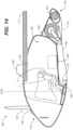
- FIG. 15 there is shown the front landing gear and rear landing gear modules, each isolated and physically removed from the airframe and shown in a fully retracted configuration, as they appear when the aircraft is in midflight cruise operation.
- FIG. 16 details of an embodiment of the landing gear structures and operational drive systems are shown. Reference numbers from the earlier views for like elements are not carried over here; instead new reference numbers are provided for similar earlier identified structures as well as for newly identified detail features.
- FIG. 16 illustrates that in an embodiment the front and rear landing gear assemblies structurally connect to, and operate in relation to, the aircraft airframe 200 so as to form a system suited for STOL operations.
- the airframe 200 (for convenience arbitrarily shown here as a section of indeterminate size) supports and connects to a front landing gear module 250 and a rear landing gear module 350.
- the airframe includes an interior surface or side 202, a longitudinally-oriented center slot 204, and left and right (port and starboard) sockets 206, 208, respectively.
- the front landing gear module 250 is operatively and pivotally connected to the airframe and its interior side 202 through the port and starboard sockets 206, 208.
- the front landing gear module includes port and starboard struts or legs 252, 254, respectively.
- Each leg includes, at a distal end, a fetlock 256, 258, pivotally connected to the leg at a fetlock pivot 260, 262; a front cradle 264, 266 (latter not showing) pivotally coupled to the fetlock at a cradle pivot 268, 270 (latter not shown); a cowling 272, 274 pivotally connected to the front cradle at a cowling pivot 276, 278; and terminating in driven wheels 280, 282, rotatingly disposed on axles 284, 286 (port side not visible).
- Drive systems/motors 288, 290 are provided for each wheel (again, port side not visible).
- Clamshell doors 292, 294 may be provided to enclose the wheels in flight.
- Each front landing gear strut 252, 254 terminates as an inboard rotatable deployment/retraction axle 300, 302, each axle disposed through an airframe socket, port and starboard, 206, 208, respectively.
- Each axle is driven by a lead screw 304, 306 pivotally connected to the axle with a pintle/gudgeon coupling 308, 310.
- the coupling and axle form bell cranks 312, 314.
- Electric motors 316, 318 are mounted to the airframe interior side 202 with a trunnion/bracket mount 320, 322, which extend their respective lead screws to retract the corresponding strut or retract their respective lead screws to deploy or extend the respective strut.
- Motor trunnions pivot at pivot points 324, 326 (latter not clearly visible). Motor control for both the deployment/retraction of the landing gear struts and for their respective drive wheels resides in system avionics described more fully below.
- the rear landing gear module 350 includes a rear leg strut 352 having a driven rear wheel 354 rotatingly coupled to the strut through an assembly that includes an axle 356 disposed through a rear wheel fork 358.
- a rear wheel drive system 360 is operatively coupled to the rear wheel.
- the rear wheel fork 358 is pivotally coupled to a rear wheel gimbal 362 through a fork/gimbal pivot 364.
- the gimbal 364 is pivotally coupled to the rear strut 352 through a gimbal/strut pivot 366.
- a rear wheel fairing 368 partially encloses the rear wheel, the enclosure selectively completed by a tail fairing door 368a.
- the rear landing gear like the front landing gear, is driven by a strut drive system, 370, which in embodiments is an electric motor. It is mounted on the airframe inner side with a motor trunnion 372 pivotally mounted on a trunnion bracket 374.
- the motor drives a lead screw 376 that engages a rear strut clevis 378 to pivot the strut on a rear strut shaft 380 disposed in a trunnion carriage 382.
- Motor control again resides in avionics control systems, described more fully below.
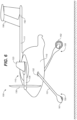
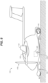
- FIGS. 6-13 , 17 and 19 Operation of the landing gear modules just described may be seen by referring now to FIGS. 6-13 , 17 and 19 , where there is shown a range of the dynamically adaptive landing gear configurations during landing and takeoff sequences.
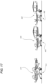
- FIG. 17 there are shown configurations of the aircraft during a takeoff sequence.
- the sequence in FIG. 17 proceeds over time from right to left.
- the landing gear can be seen to be in a taxiing configuration 402. Both front and rear wheel steering are enabled and the wheels may be selectively driven, as needed.
- the aircraft landing gear is in its ground roll configuration 408, similar to the taxiing configuration except that the front landing gear has limited steering and the rear wheel is powered and its steering is locked.
- the landing gear control system rotates the front landing gear downwardly into a rotation configuration 412 to drive the aircraft nose up, increasing the angle of attack and dramatically and rapidly increasing lift.
- the rotation configuration 412 is shown more clearly in FIG. 9 .
- FIG. 19 shows a sequence of landing gear configurations corresponding to a typical landing as might be accomplished using the advantageous dynamically active landing gear of the present invention.
- FIG. 19 shows the developing configurations.
- the front and rear landing gear struts are fully retracted and folded underneath the airframe in a cruise flight configuration 422.
- the front landing gear is activated and deployed into an approach configuration 432.
- This may be characterized as a "reaching forward" configuration.
- flight system controls align the aircraft and place it on an approach vector and glide slope that will enable it to land safely on the STOL runway.
- the target cloud referred to herein is a virtual envelope enclosing a predetermined volume of airspace defined by a range of possible safe landing positions above and close to the runway threshold on the approach when the aircraft meets certain parameters (e.g. ground speed).
- the target cloud may be a cuboid airspace having 10 x 10 x 1 meter dimensions.
- FIGS. 6-8 show configurations intermediate those of FIG. 17 .
- FIG. 6 shows the aircraft landing gear configuration as the target cloud is reached.
- FIG. 7 shows the landing gear as the energy of the vertical sink is absorbed by the landing gear.
- FIG. 8 shows the configuration as the landing gear reaches the taxiing configuration.
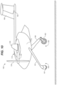
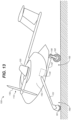
- FIGS. 10-12 show an alternative landing gear assembly in landing gear configurations corresponding in sequence to the landing gear configurations shown in FIGS. 6-9 .
- the salient alternative features include a rear landing gear wheel 162 rotatable about a pivot at the distal end of the rear landing great strut 156 so as to enhance the "reaching" feature during landing.
- the front landing gear wheels have a similar feature, enabling them to pivot and extend downwardly as the plane approaches the runway.
- the avionics system controls the landing gear deployment in coordination with the propeller and wheel drives for the precise movement with respect to location and speed to fully enable the STOL advantages.
- Such an avionics control system may be capable of remote or drone control, as well as autonomous or semi-autonomous control. More pertinently, the landing gear system control may be pilot controlled or, in a pilotless/autonomously controlled embodiment, controlled with on-board system avionics or remotely controlled from a centralized control system.
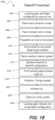
- FIG. 18 shows the conditions monitored and actions taken by the control systems during a takeoff sequence 500.
- Cabin conditions, passenger safety checks, scheduling taxi and takeoff movements according to skyport/airport and area traffic, and the like are understood and assumed, and therefore not set out here. Rather, the focus is on the role played by the aircraft landing gear in facilitating a short field takeoff. Mention should be made, however, that all pre-flight activities are handled either by system controls alone or in combination with actions by flight personnel. For instance, in preparation for flight, the aircraft doors are closed and the plane shifted from a loading configuration to a taxi configuration, and the cabin and any passengers are readied for flight.
- the landing gear and flaps are configured for ground roll 502, and plane then taxis toward the runway 504.
- the landing gear is pulled up (wheels up) 520, and the plane is then configured 522 for optimal climb performance according to the climb requirements needed to clear obstacles, to remain clear of other traffic in the urban Traffic Control Area, and to achieve level flight altitude.
- the landing gear is then fully retracted into cruise flight configuration 524 and the aircraft proceeds to its destination.
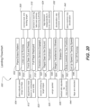
- FIG. 20 shows the conditions monitored and the actions taken by the aircraft control systems as the aircraft approaches its destination and during the landing sequence at the destination 600.
- the aircraft enters an airport/skyport traffic pattern 602 its speed and flap configuration are adjusted 604.
- the aircraft turns to a final approach heading and is aligned with the runway centerline 606.
- Aircraft sensors then lock onto the landing target (the above-described target cloud) 608 and the front landing gear is extended outwardly 610 and readied for dynamic adjustments immediately preceding touchdown. Further fine adjustments are made in response to air and wind conditions and aircraft flight conditions (loading, groundspeed, wind direction, current flight control configurations, etc.) 612. Full flaps are deployed as needed 614.
- the landing gear is moved into a taxi configuration 638.
- the aircraft will quickly reach maximum deceleration 640, and it will continue a short roll at taxi speed 642.
- the flaps are retracted 644, and the plane taxis off the runway 646, ready for unloading and for preparations for a next flight.
Landscapes
- Engineering & Computer Science (AREA)
- Aviation & Aerospace Engineering (AREA)
- Mechanical Engineering (AREA)
- Retarders (AREA)
- Transmission Devices (AREA)
- Traffic Control Systems (AREA)
- Toys (AREA)
Claims (14)
- STOL-Flugzeug (100), das Folgendes umfasst:einen Rumpf (110), der eine Backbord- und eine Steuerbordseite aufweist,ein Paar von entgegengesetzten festen Tragflächen (120, 120'), die mindestens eine feste Tragfläche sind, die mit dem Rumpf verbunden ist und sich seitlich von sowohl der Backbord- als auch der Steuerbordseite aus erstreckt,einen oder mehrere Propeller (130, 130'), die mit mindestens einem von den Tragflächen oder dem Rumpf verbunden sind, um einen axial gerichteten Schub bereitzustellen, um das Flugzeug vorwärts anzutreiben,einen oder mehrere Motoren (135, 135'), um die Propeller anzutreiben,mindestens eine Energiequelle (140), die mit dem einen oder den mehreren Motoren verbunden ist, um dem einen oder den mehreren Motoren Energie zuzuführen, unddrei oder mehr einziehbare und ausfahrbare Fahrwerksmodule (150, 155), die mit einem oder mehreren von dem Rumpf und den Tragflächen verbunden und funktionsfähig sind, um sich während einer Landung zu drehen, um vertikale Sinkenergie des Flugzeugs zu absorbieren und um eine Erschütterung für Flugzeuginsassen zu verringern, wobei die Fahrwerksmodule ein vorderes und ein hinteres Fahrwerksmodul einschließen, wobei die vorderen und die hinteren Fahrwerksmodule wirksam mit dem Rumpf verbunden sind, wobei jedes von den vorderen und den hinteren Fahrwerksmodulen mindestens eine drehbare Fahrwerksstrebe (151, 151', 156) mit einem Rad (161, 161', 162), das an ihrem distalen Ende angeordnet ist, einschließt, wobei das Rad des hinteren Fahrwerks angetrieben ist,ein Steuerungssystem zum Steuern der Fahrwerksmotoren, um die vorderen und die hinteren Fahrwerksstreben auszufahren und einzuziehen,Fahrwerksmotoren (1520) zum unabhängigen Antreiben der vorderen und der hinteren Fahrwerksstreben undSensoren, die dafür konfiguriert sind, Flugzeug-Flugbedingungs- und -Positionsdaten, einschließlich von Fluggeschwindigkeit, Bodengeschwindigkeit und Position im Verhältnis zu einer Start- und Landebahn, zu messen und Messungen für das Steuerungssystem bereitzustellen,wobei der Flugzeugschwerpunkt (COG) zwischen dem vorderen und dem hinteren Fahrwerksmodul angeordnet ist und das vordere Fahrwerksmodul dafür konfiguriert ist, sich während einer Startanlaufstrecke zum Boden hin zu drehen, wobei eine Nase des Flugzeugs nach oben gedrückt wird, undwobei das Steuerungssystem dafür konfiguriert ist, eine oder mehrere der Fahrwerksstreben als Reaktion auf Flugzeug-Flugbedingungs- und -Positionsdaten zu drehen.
- STOL-Flugzeug (100) nach Anspruch 1, wobei das Steuerungssystem ein Fahrwerk-Steuerungssystem ist, das funktionsfähig ist, um ein Fahrwerk (150, 155) bei einer Annäherung zur Landung derart abzusenken, dass die vertikale Reaktionskraft der Landung hauptsächlich durch das Fahrwerk absorbiert wird.
- STOL-Flugzeug (100) nach Anspruch 1, wobei zumindest das vordere Fahrwerksmodul (150) ein lineares Strebenelement (151, 151') umfasst, das durch ein Drehgelenk (152) an einem proximalen Ende mit dem Rumpf (110) verbunden ist, wobei das distale Ende mindestens ein Rad (161, 161') in drehendem Eingriff stützt.
- STOL-Flugzeug (100) nach Anspruch 3, wobei eine Drehung des vorderen Fahrwerksmoduls (150) zum Boden hin dadurch bereitgestellt wird, dass das lineare Strebenelement (151, 151') funktionsfähig ist, um sich während eines Starts zu drehen, um eine Drehung und ein Anheben des Rumpfes (110) zu gewährleisten.
- STOL-Flugzeug (100) nach Anspruch 4, wobei das lineare Strebenelement (151, 151') ein von einem Motor (1520) angetriebenes Rad aufweist, um das Flugzeug am Boden während des Starts zu beschleunigen.
- STOL-Flugzeug nach Anspruch 1, wobei mindestens eines der Räder (161, 161', 162) der vorderen Fahrwerksstrebe (151, 151') motorgetrieben ist.
- STOL-Flugzeug nach Anspruch 6, wobei die vordere Fahrwerksstrebe (151, 151') mehr als ein Rad (161, 161') umfasst und jedes der Räder (161, 161') motorgetrieben ist.
- STOL-Flugzeug nach Anspruch 1, wobei das vordere Fahrwerk (150) eine Backbord-Fahrwerksstrebe (151) und eine Steuerbord-Fahrwerksstrebe (151') einschließt, die jeweils drehbar mit dem Rumpf (110) verbunden sind.
- STOL-Flugzeug nach Anspruch 8, wobei die vorderen Fahrwerksstreben (151, 151') unabhängig gesteuert werden und unabhängig voneinander ausgefahren und eingezogen werden können.
- STOL-Flugzeug nach Anspruch 8, wobei, um das vordere Fahrzeugmodul (150) während der Startanlaufstrecke zum Boden hin zu drehen, das Steuerungssystem dafür programmiert ist, die mindestens eine vordere Fahrwerksstrebe (151, 151') während des Starts nach unten anzutreiben, um den Flugzeug-Anstellwinkel zu vergrößern.
- STOL-Flugzeug nach Anspruch 8, wobei das Steuerungssystem dafür konfiguriert ist, die mindestens eine vordere Fahrwerksstrebe (151, 151') während einer Landung nach unten anzutreiben, um eine Bodenberührung durch das Rad (161, 161') der vorderen Fahrwerksstrebe zu beschleunigen.
- STOL-Flugzeug nach Anspruch 8, wobei das Steuerungssystem dafür konfiguriert ist, die vorderen und die hinteren Fahrwerksstreben (151, 151', 156) während einer Landung nach unten anzutreiben, um eine Bodenberührung durch die Räder (161, 161', 162) der vorderen und der hinteren Fahrwerksstreben zu beschleunigen.
- STOL-Flugzeug nach Anspruch 8, wobei das Steuerungssystem dafür konfiguriert ist, die vorderen und die hinteren Fahrwerksstreben (151, 151', 156) während einer Landung nach unten anzutreiben, um eine Bodenberührung durch die Räder (161, 161', 162) der vorderen und der hinteren Fahrwerksstreben zu beschleunigen.
- STOL-Flugzeug nach Anspruch 13, wobei das Steuerungssystem dafür konfiguriert ist, das Fahrwerk (150, 155) nach einem Aufsetzen bei der Landung zu drehen, um die Energie zu absorbieren.
Applications Claiming Priority (2)
| Application Number | Priority Date | Filing Date | Title |
|---|---|---|---|
| US201762505890P | 2017-05-13 | 2017-05-13 | |
| PCT/US2018/032568 WO2018213190A1 (en) | 2017-05-13 | 2018-05-14 | Stol aircraft |
Publications (3)
| Publication Number | Publication Date |
|---|---|
| EP3621876A1 EP3621876A1 (de) | 2020-03-18 |
| EP3621876A4 EP3621876A4 (de) | 2021-01-27 |
| EP3621876B1 true EP3621876B1 (de) | 2025-03-26 |
Family
ID=64274646
Family Applications (1)
| Application Number | Title | Priority Date | Filing Date |
|---|---|---|---|
| EP18801340.3A Active EP3621876B1 (de) | 2017-05-13 | 2018-05-14 | Stol-flugzeug |
Country Status (4)
| Country | Link |
|---|---|
| US (2) | US11292585B2 (de) |
| EP (1) | EP3621876B1 (de) |
| CN (1) | CN110914148A (de) |
| WO (2) | WO2018213190A1 (de) |
Families Citing this family (12)
| Publication number | Priority date | Publication date | Assignee | Title |
|---|---|---|---|---|
| US9550567B1 (en) * | 2014-10-27 | 2017-01-24 | Amazon Technologies, Inc. | In-flight reconfigurable hybrid unmanned aerial vehicle |
| EP3621876B1 (de) * | 2017-05-13 | 2025-03-26 | Bruno Mombrinie | Stol-flugzeug |
| US11675324B2 (en) * | 2019-09-19 | 2023-06-13 | Bao Tran | Air transportation systems and methods |
| WO2021062434A2 (en) * | 2019-09-23 | 2021-04-01 | Bruno Mombrinie | Urban air mobility cargo module swapping system |
| GB2587669A (en) * | 2019-10-02 | 2021-04-07 | Advanced Mobility Res And Development Ltd | Systems and methods for aircraft |
| US11708153B2 (en) * | 2020-02-22 | 2023-07-25 | ZeroAvia, Inc. | Electric acceleration assist for short takeoff and landing capabilities in fixed-wing aircraft |
| CN113291460B (zh) * | 2021-06-02 | 2022-11-11 | 南京航空航天大学 | 一种采用变体起落架的短距/垂直起降飞行器 |
| CN113525671A (zh) * | 2021-07-30 | 2021-10-22 | 深圳市道通智能航空技术股份有限公司 | 一种起落架以及无人机 |
| US11472538B1 (en) | 2021-10-30 | 2022-10-18 | Beta Air, Llc | Landing gear assembly for reducing drag on an aircraft |
| EP4183688A1 (de) * | 2021-11-18 | 2023-05-24 | Lilium eAircraft GmbH | Elektrisch angetriebenes flugzeug |
| US12371158B2 (en) | 2023-01-30 | 2025-07-29 | Textron Eaviation Inc. | Aft swept spring main landing gear |
| KR102712524B1 (ko) * | 2023-10-16 | 2024-10-02 | 주식회사 유에이엠테크 | 비행 효율이 향상되는 텐덤형 수직이착륙기 |
Family Cites Families (30)
| Publication number | Priority date | Publication date | Assignee | Title |
|---|---|---|---|---|
| US1850711A (en) * | 1931-01-29 | 1932-03-22 | Jacob Brandt | Aeroplane lifting and driving device |
| GB526904A (en) | 1938-04-08 | 1940-09-27 | Rene Tampier | Improvements in or relating to aircraft |
| US2396628A (en) * | 1941-11-07 | 1946-03-12 | Bell Aircraft Corp | Airplane |
| US2533548A (en) * | 1947-05-16 | 1950-12-12 | Nl Vliegtuigenfabriek Fokker N | Cockpit cover for airplanes |
| US2909342A (en) * | 1954-06-04 | 1959-10-20 | Menasco Mfg Company | Landing gear for helicopters |
| US2933270A (en) | 1954-06-04 | 1960-04-19 | Menasco Mfg Company | Landing gear for helicopters |
| US3329376A (en) | 1965-09-07 | 1967-07-04 | Paul D Sullivan | Short takeoff and landing aircraft |
| US3511455A (en) | 1968-05-23 | 1970-05-12 | Piper Aircraft Corp | Retractable landing gear system for aircraft |
| GB1593393A (en) | 1978-02-24 | 1981-07-15 | Secr Defence | Aircraft |
| US4881700A (en) * | 1988-01-05 | 1989-11-21 | Branko Sarh | Convertible fixed wing aircraft |
| US4914783A (en) * | 1988-12-05 | 1990-04-10 | The Hartwell Corporation | Sliding hinge with locking |
| US5758844A (en) | 1996-05-28 | 1998-06-02 | Boeing North American, Inc. | Vertical/short take-off and landing (V/STOL) air vehicle capable of providing high speed horizontal flight |
| US5915649A (en) * | 1996-08-23 | 1999-06-29 | Mcdonnell Douglas Helicopter Company | Roadable helicopter |
| US6854689B1 (en) | 2004-02-09 | 2005-02-15 | The Boeing Company | Methods and systems for operating aircraft landing gears |
| US7147182B1 (en) * | 2004-02-23 | 2006-12-12 | Kenneth Warren Flanigan | Gas-powered tip-jet-driven tilt-rotor compound VTOL aircraft |
| US7249736B2 (en) * | 2005-06-23 | 2007-07-31 | Northrop Grumman Corporation | Process for landing a tailless aircraft |
| US8256704B2 (en) | 2007-08-14 | 2012-09-04 | Lapcad Engineering, Inc. | Vertical/short take-off and landing aircraft |
| GB0717903D0 (en) | 2007-09-14 | 2007-10-31 | Airbus Uk Ltd | Method and apparatus for providing power in an aircraft to one or more aircraft systems |
| RU2381143C1 (ru) * | 2008-07-16 | 2010-02-10 | Вячеслав Петрович Кондратьев | Легкий двухмоторный самолет |
| FR2951697B1 (fr) | 2009-10-23 | 2012-04-20 | Messier Dowty Sa | Dispositif de manoeuvre d'un atterrisseur d'aeronef |
| GB2529483A (en) * | 2014-08-22 | 2016-02-24 | Airbus Operations Ltd | A landing gear assembly |
| US9499260B2 (en) | 2014-10-14 | 2016-11-22 | Honeywell International Inc. | Aircraft landing gear wheel with integral gear drive |
| DE102015105706A1 (de) * | 2015-04-14 | 2016-10-20 | Johann Schwöller | Flugzeug |
| US10689098B2 (en) * | 2015-06-25 | 2020-06-23 | Sikorsky Aircraft Corporation | Adaptive landing gear assembly for rotary wing aircraft |
| KR101743834B1 (ko) * | 2015-10-12 | 2017-06-07 | 한국항공우주연구원 | 비행체 |
| CN205499344U (zh) * | 2016-03-15 | 2016-08-24 | 中航沈飞民用飞机有限责任公司 | 一种可升降式轻型飞机起落架 |
| US10150558B2 (en) * | 2016-06-30 | 2018-12-11 | DZYNE Technologies Incorporated | Tilting landing gear systems and methods |
| RO131684A0 (ro) | 2016-09-27 | 2017-02-28 | Liviu Grigorian Giurca | Aeronave cu decolare şi aterizare pe verticală |
| EP3621876B1 (de) * | 2017-05-13 | 2025-03-26 | Bruno Mombrinie | Stol-flugzeug |
| US11077940B2 (en) * | 2018-09-05 | 2021-08-03 | Stian Nilsen | Aircraft and method of use |
-
2018
- 2018-05-14 EP EP18801340.3A patent/EP3621876B1/de active Active
- 2018-05-14 US US16/613,035 patent/US11292585B2/en active Active
- 2018-05-14 WO PCT/US2018/032568 patent/WO2018213190A1/en not_active Ceased
- 2018-05-14 CN CN201880044339.8A patent/CN110914148A/zh active Pending
-
2019
- 2019-11-26 US US16/697,069 patent/US11279473B2/en active Active
-
2020
- 2020-11-25 WO PCT/US2020/062370 patent/WO2021108669A1/en not_active Ceased
Also Published As
| Publication number | Publication date |
|---|---|
| US11292585B2 (en) | 2022-04-05 |
| US11279473B2 (en) | 2022-03-22 |
| US20200156770A1 (en) | 2020-05-21 |
| WO2018213190A1 (en) | 2018-11-22 |
| CN110914148A (zh) | 2020-03-24 |
| WO2021108669A1 (en) | 2021-06-03 |
| EP3621876A4 (de) | 2021-01-27 |
| US20200102068A1 (en) | 2020-04-02 |
| EP3621876A1 (de) | 2020-03-18 |
Similar Documents
| Publication | Publication Date | Title |
|---|---|---|
| EP3621876B1 (de) | Stol-flugzeug | |
| CN112004746B (zh) | 自主飞行救护车 | |
| CN108116668B (zh) | 陆空两用全电多旋翼载人飞行器 | |
| US9139299B2 (en) | Vertical takeoff and landing roadable vehicle | |
| US20140312177A1 (en) | Coaxial rotor/wing aircraft | |
| US20210403155A1 (en) | Vtol aircraft | |
| US20050109874A1 (en) | Vertical lift flying craft | |
| EP3768592B1 (de) | Strukturkonstruktion für ein flugzeug und flugzeug mit dieser strukturkonstruktion | |
| US11993161B2 (en) | External power assist systems for charging batteries onboard eVTOL aircraft | |
| US12017770B2 (en) | Electric-propulsion aircraft comprising a central wing and two rotatable lateral wings | |
| US20200354050A1 (en) | Convertiplane | |
| CN114476050A (zh) | 一种倾转涵道固定翼飞行器 | |
| CN202728571U (zh) | 私人飞行器 | |
| US12358617B2 (en) | Convertible aircraft capable of hovering | |
| KR20220108309A (ko) | 가변형 주익을 구비하여 수직이착륙이 가능한 글라이더 드론 | |
| RU2648937C1 (ru) | Аэромобиль вертикального взлета | |
| RU192967U1 (ru) | Самолет сверхкороткого взлета и посадки | |
| CA2776121A1 (en) | Coaxial rotor/wing aircraft | |
| CN111086625A (zh) | 双涵道可变座舱尾座式垂直起降载人固定翼飞行器 | |
| GB2582133A (en) | Tail sitter helicraft | |
| AU2020100605A4 (en) | A vtol-capable airplane having angled propulsors | |
| CN212194977U (zh) | 一种电动飞行汽车及电动飞行汽车控制装置 | |
| GB2592063A (en) | VTOL Aircraft with contra-rotating fans | |
| JP2014065477A (ja) | 垂直水平離着陸飛行機 | |
| RU2771536C1 (ru) | Беспилотный летательный аппарат вертикального взлета и посадки |
Legal Events
| Date | Code | Title | Description |
|---|---|---|---|
| STAA | Information on the status of an ep patent application or granted ep patent |
Free format text: STATUS: THE INTERNATIONAL PUBLICATION HAS BEEN MADE |
|
| PUAI | Public reference made under article 153(3) epc to a published international application that has entered the european phase |
Free format text: ORIGINAL CODE: 0009012 |
|
| STAA | Information on the status of an ep patent application or granted ep patent |
Free format text: STATUS: REQUEST FOR EXAMINATION WAS MADE |
|
| 17P | Request for examination filed |
Effective date: 20191204 |
|
| AK | Designated contracting states |
Kind code of ref document: A1 Designated state(s): AL AT BE BG CH CY CZ DE DK EE ES FI FR GB GR HR HU IE IS IT LI LT LU LV MC MK MT NL NO PL PT RO RS SE SI SK SM TR |
|
| AX | Request for extension of the european patent |
Extension state: BA ME |
|
| DAV | Request for validation of the european patent (deleted) | ||
| DAX | Request for extension of the european patent (deleted) | ||
| REG | Reference to a national code |
Ref country code: DE Ref legal event code: R079 Free format text: PREVIOUS MAIN CLASS: B64C0025100000 Ipc: B64C0025140000 |
|
| A4 | Supplementary search report drawn up and despatched |
Effective date: 20210112 |
|
| RIC1 | Information provided on ipc code assigned before grant |
Ipc: B64C 25/14 20060101AFI20201221BHEP Ipc: B64C 29/00 20060101ALI20201221BHEP Ipc: B64C 25/40 20060101ALI20201221BHEP Ipc: B64C 25/24 20060101ALI20201221BHEP |
|
| STAA | Information on the status of an ep patent application or granted ep patent |
Free format text: STATUS: EXAMINATION IS IN PROGRESS |
|
| 17Q | First examination report despatched |
Effective date: 20220325 |
|
| GRAP | Despatch of communication of intention to grant a patent |
Free format text: ORIGINAL CODE: EPIDOSNIGR1 |
|
| STAA | Information on the status of an ep patent application or granted ep patent |
Free format text: STATUS: GRANT OF PATENT IS INTENDED |
|
| INTG | Intention to grant announced |
Effective date: 20241016 |
|
| P01 | Opt-out of the competence of the unified patent court (upc) registered |
Free format text: CASE NUMBER: APP_62346/2024 Effective date: 20241121 |
|
| GRAS | Grant fee paid |
Free format text: ORIGINAL CODE: EPIDOSNIGR3 |
|
| GRAA | (expected) grant |
Free format text: ORIGINAL CODE: 0009210 |
|
| STAA | Information on the status of an ep patent application or granted ep patent |
Free format text: STATUS: THE PATENT HAS BEEN GRANTED |
|
| AK | Designated contracting states |
Kind code of ref document: B1 Designated state(s): AL AT BE BG CH CY CZ DE DK EE ES FI FR GB GR HR HU IE IS IT LI LT LU LV MC MK MT NL NO PL PT RO RS SE SI SK SM TR |
|
| REG | Reference to a national code |
Ref country code: GB Ref legal event code: FG4D |
|
| REG | Reference to a national code |
Ref country code: CH Ref legal event code: EP |
|
| REG | Reference to a national code |
Ref country code: DE Ref legal event code: R096 Ref document number: 602018080502 Country of ref document: DE |
|
| REG | Reference to a national code |
Ref country code: IE Ref legal event code: FG4D |
|
| PG25 | Lapsed in a contracting state [announced via postgrant information from national office to epo] |
Ref country code: RS Free format text: LAPSE BECAUSE OF FAILURE TO SUBMIT A TRANSLATION OF THE DESCRIPTION OR TO PAY THE FEE WITHIN THE PRESCRIBED TIME-LIMIT Effective date: 20250626 |
|
| PG25 | Lapsed in a contracting state [announced via postgrant information from national office to epo] |
Ref country code: FI Free format text: LAPSE BECAUSE OF FAILURE TO SUBMIT A TRANSLATION OF THE DESCRIPTION OR TO PAY THE FEE WITHIN THE PRESCRIBED TIME-LIMIT Effective date: 20250326 |
|
| PGFP | Annual fee paid to national office [announced via postgrant information from national office to epo] |
Ref country code: DE Payment date: 20250603 Year of fee payment: 8 |
|
| REG | Reference to a national code |
Ref country code: LT Ref legal event code: MG9D |
|
| PG25 | Lapsed in a contracting state [announced via postgrant information from national office to epo] |
Ref country code: NO Free format text: LAPSE BECAUSE OF FAILURE TO SUBMIT A TRANSLATION OF THE DESCRIPTION OR TO PAY THE FEE WITHIN THE PRESCRIBED TIME-LIMIT Effective date: 20250626 |
|
| PG25 | Lapsed in a contracting state [announced via postgrant information from national office to epo] |
Ref country code: HR Free format text: LAPSE BECAUSE OF FAILURE TO SUBMIT A TRANSLATION OF THE DESCRIPTION OR TO PAY THE FEE WITHIN THE PRESCRIBED TIME-LIMIT Effective date: 20250326 |
|
| PG25 | Lapsed in a contracting state [announced via postgrant information from national office to epo] |
Ref country code: LV Free format text: LAPSE BECAUSE OF FAILURE TO SUBMIT A TRANSLATION OF THE DESCRIPTION OR TO PAY THE FEE WITHIN THE PRESCRIBED TIME-LIMIT Effective date: 20250326 |
|
| PGFP | Annual fee paid to national office [announced via postgrant information from national office to epo] |
Ref country code: FR Payment date: 20250509 Year of fee payment: 8 |
|
| PG25 | Lapsed in a contracting state [announced via postgrant information from national office to epo] |
Ref country code: GR Free format text: LAPSE BECAUSE OF FAILURE TO SUBMIT A TRANSLATION OF THE DESCRIPTION OR TO PAY THE FEE WITHIN THE PRESCRIBED TIME-LIMIT Effective date: 20250627 Ref country code: BG Free format text: LAPSE BECAUSE OF FAILURE TO SUBMIT A TRANSLATION OF THE DESCRIPTION OR TO PAY THE FEE WITHIN THE PRESCRIBED TIME-LIMIT Effective date: 20250326 |
|
| REG | Reference to a national code |
Ref country code: NL Ref legal event code: MP Effective date: 20250326 |
|
| PG25 | Lapsed in a contracting state [announced via postgrant information from national office to epo] |
Ref country code: NL Free format text: LAPSE BECAUSE OF FAILURE TO SUBMIT A TRANSLATION OF THE DESCRIPTION OR TO PAY THE FEE WITHIN THE PRESCRIBED TIME-LIMIT Effective date: 20250326 |
|
| PG25 | Lapsed in a contracting state [announced via postgrant information from national office to epo] |
Ref country code: SE Free format text: LAPSE BECAUSE OF FAILURE TO SUBMIT A TRANSLATION OF THE DESCRIPTION OR TO PAY THE FEE WITHIN THE PRESCRIBED TIME-LIMIT Effective date: 20250326 |
|
| REG | Reference to a national code |
Ref country code: AT Ref legal event code: MK05 Ref document number: 1778836 Country of ref document: AT Kind code of ref document: T Effective date: 20250326 |
|
| PG25 | Lapsed in a contracting state [announced via postgrant information from national office to epo] |
Ref country code: SM Free format text: LAPSE BECAUSE OF FAILURE TO SUBMIT A TRANSLATION OF THE DESCRIPTION OR TO PAY THE FEE WITHIN THE PRESCRIBED TIME-LIMIT Effective date: 20250326 |
|
| PG25 | Lapsed in a contracting state [announced via postgrant information from national office to epo] |
Ref country code: PT Free format text: LAPSE BECAUSE OF FAILURE TO SUBMIT A TRANSLATION OF THE DESCRIPTION OR TO PAY THE FEE WITHIN THE PRESCRIBED TIME-LIMIT Effective date: 20250728 Ref country code: ES Free format text: LAPSE BECAUSE OF FAILURE TO SUBMIT A TRANSLATION OF THE DESCRIPTION OR TO PAY THE FEE WITHIN THE PRESCRIBED TIME-LIMIT Effective date: 20250326 |
|
| PG25 | Lapsed in a contracting state [announced via postgrant information from national office to epo] |
Ref country code: IT Free format text: LAPSE BECAUSE OF FAILURE TO SUBMIT A TRANSLATION OF THE DESCRIPTION OR TO PAY THE FEE WITHIN THE PRESCRIBED TIME-LIMIT Effective date: 20250326 Ref country code: PL Free format text: LAPSE BECAUSE OF FAILURE TO SUBMIT A TRANSLATION OF THE DESCRIPTION OR TO PAY THE FEE WITHIN THE PRESCRIBED TIME-LIMIT Effective date: 20250326 |
|
| PG25 | Lapsed in a contracting state [announced via postgrant information from national office to epo] |
Ref country code: AT Free format text: LAPSE BECAUSE OF FAILURE TO SUBMIT A TRANSLATION OF THE DESCRIPTION OR TO PAY THE FEE WITHIN THE PRESCRIBED TIME-LIMIT Effective date: 20250326 |
|
| PG25 | Lapsed in a contracting state [announced via postgrant information from national office to epo] |
Ref country code: EE Free format text: LAPSE BECAUSE OF FAILURE TO SUBMIT A TRANSLATION OF THE DESCRIPTION OR TO PAY THE FEE WITHIN THE PRESCRIBED TIME-LIMIT Effective date: 20250326 |
|
| PG25 | Lapsed in a contracting state [announced via postgrant information from national office to epo] |
Ref country code: RO Free format text: LAPSE BECAUSE OF FAILURE TO SUBMIT A TRANSLATION OF THE DESCRIPTION OR TO PAY THE FEE WITHIN THE PRESCRIBED TIME-LIMIT Effective date: 20250326 |
|
| PG25 | Lapsed in a contracting state [announced via postgrant information from national office to epo] |
Ref country code: SK Free format text: LAPSE BECAUSE OF FAILURE TO SUBMIT A TRANSLATION OF THE DESCRIPTION OR TO PAY THE FEE WITHIN THE PRESCRIBED TIME-LIMIT Effective date: 20250326 |
|
| PG25 | Lapsed in a contracting state [announced via postgrant information from national office to epo] |
Ref country code: IS Free format text: LAPSE BECAUSE OF FAILURE TO SUBMIT A TRANSLATION OF THE DESCRIPTION OR TO PAY THE FEE WITHIN THE PRESCRIBED TIME-LIMIT Effective date: 20250726 |
|
| REG | Reference to a national code |
Ref country code: CH Ref legal event code: H13 Free format text: ST27 STATUS EVENT CODE: U-0-0-H10-H13 (AS PROVIDED BY THE NATIONAL OFFICE) Effective date: 20251223 |
|
| REG | Reference to a national code |
Ref country code: DE Ref legal event code: R097 Ref document number: 602018080502 Country of ref document: DE |
|
| PG25 | Lapsed in a contracting state [announced via postgrant information from national office to epo] |
Ref country code: DK Free format text: LAPSE BECAUSE OF FAILURE TO SUBMIT A TRANSLATION OF THE DESCRIPTION OR TO PAY THE FEE WITHIN THE PRESCRIBED TIME-LIMIT Effective date: 20250326 |
|
| PG25 | Lapsed in a contracting state [announced via postgrant information from national office to epo] |
Ref country code: LU Free format text: LAPSE BECAUSE OF NON-PAYMENT OF DUE FEES Effective date: 20250514 |
|
| PG25 | Lapsed in a contracting state [announced via postgrant information from national office to epo] |
Ref country code: CH Free format text: LAPSE BECAUSE OF NON-PAYMENT OF DUE FEES Effective date: 20250531 |
|
| PG25 | Lapsed in a contracting state [announced via postgrant information from national office to epo] |
Ref country code: CZ Free format text: LAPSE BECAUSE OF FAILURE TO SUBMIT A TRANSLATION OF THE DESCRIPTION OR TO PAY THE FEE WITHIN THE PRESCRIBED TIME-LIMIT Effective date: 20250326 |
|
| REG | Reference to a national code |
Ref country code: BE Ref legal event code: MM Effective date: 20250531 |
|
| PG25 | Lapsed in a contracting state [announced via postgrant information from national office to epo] |
Ref country code: MC Free format text: LAPSE BECAUSE OF FAILURE TO SUBMIT A TRANSLATION OF THE DESCRIPTION OR TO PAY THE FEE WITHIN THE PRESCRIBED TIME-LIMIT Effective date: 20250326 |
|
| PLBE | No opposition filed within time limit |
Free format text: ORIGINAL CODE: 0009261 |
|
| STAA | Information on the status of an ep patent application or granted ep patent |
Free format text: STATUS: NO OPPOSITION FILED WITHIN TIME LIMIT |
|
| REG | Reference to a national code |
Ref country code: CH Ref legal event code: L10 Free format text: ST27 STATUS EVENT CODE: U-0-0-L10-L00 (AS PROVIDED BY THE NATIONAL OFFICE) Effective date: 20260211 |
|
| GBPC | Gb: european patent ceased through non-payment of renewal fee |
Effective date: 20250626 |
|
| 26N | No opposition filed |
Effective date: 20260105 |
|
| PG25 | Lapsed in a contracting state [announced via postgrant information from national office to epo] |
Ref country code: GB Free format text: LAPSE BECAUSE OF NON-PAYMENT OF DUE FEES Effective date: 20250626 |
|
| PG25 | Lapsed in a contracting state [announced via postgrant information from national office to epo] |
Ref country code: IE Free format text: LAPSE BECAUSE OF NON-PAYMENT OF DUE FEES Effective date: 20250514 |
|
| PG25 | Lapsed in a contracting state [announced via postgrant information from national office to epo] |
Ref country code: BE Free format text: LAPSE BECAUSE OF NON-PAYMENT OF DUE FEES Effective date: 20250531 |