EP3622148B1 - Ensemble destiné à guider une porte coulissante ou une porte coulissante pliante - Google Patents
Ensemble destiné à guider une porte coulissante ou une porte coulissante pliante Download PDFInfo
- Publication number
- EP3622148B1 EP3622148B1 EP18729538.1A EP18729538A EP3622148B1 EP 3622148 B1 EP3622148 B1 EP 3622148B1 EP 18729538 A EP18729538 A EP 18729538A EP 3622148 B1 EP3622148 B1 EP 3622148B1
- Authority
- EP
- European Patent Office
- Prior art keywords
- guide
- support
- sliding door
- arrangement
- segments
- Prior art date
- Legal status (The legal status is an assumption and is not a legal conclusion. Google has not performed a legal analysis and makes no representation as to the accuracy of the status listed.)
- Active
Links
Images





Classifications
-
- E—FIXED CONSTRUCTIONS
- E05—LOCKS; KEYS; WINDOW OR DOOR FITTINGS; SAFES
- E05D—HINGES OR SUSPENSION DEVICES FOR DOORS, WINDOWS OR WINGS
- E05D15/00—Suspension arrangements for wings
- E05D15/56—Suspension arrangements for wings with successive different movements
- E05D15/58—Suspension arrangements for wings with successive different movements with both swinging and sliding movements
-
- E—FIXED CONSTRUCTIONS
- E05—LOCKS; KEYS; WINDOW OR DOOR FITTINGS; SAFES
- E05D—HINGES OR SUSPENSION DEVICES FOR DOORS, WINDOWS OR WINGS
- E05D15/00—Suspension arrangements for wings
- E05D15/56—Suspension arrangements for wings with successive different movements
- E05D15/58—Suspension arrangements for wings with successive different movements with both swinging and sliding movements
- E05D15/581—Suspension arrangements for wings with successive different movements with both swinging and sliding movements the swinging axis laying in the sliding direction
-
- E—FIXED CONSTRUCTIONS
- E05—LOCKS; KEYS; WINDOW OR DOOR FITTINGS; SAFES
- E05D—HINGES OR SUSPENSION DEVICES FOR DOORS, WINDOWS OR WINGS
- E05D15/00—Suspension arrangements for wings
- E05D15/26—Suspension arrangements for wings for folding wings
- E05D15/264—Suspension arrangements for wings for folding wings for bi-fold wings
-
- E—FIXED CONSTRUCTIONS
- E06—DOORS, WINDOWS, SHUTTERS, OR ROLLER BLINDS IN GENERAL; LADDERS
- E06B—FIXED OR MOVABLE CLOSURES FOR OPENINGS IN BUILDINGS, VEHICLES, FENCES OR LIKE ENCLOSURES IN GENERAL, e.g. DOORS, WINDOWS, BLINDS, GATES
- E06B3/00—Window sashes, door leaves, or like elements for closing wall or like openings; Layout of fixed or moving closures, e.g. windows in wall or like openings; Features of rigidly-mounted outer frames relating to the mounting of wing frames
- E06B3/32—Arrangements of wings characterised by the manner of movement; Arrangements of movable wings in openings; Features of wings or frames relating solely to the manner of movement of the wing
- E06B3/50—Arrangements of wings characterised by the manner of movement; Arrangements of movable wings in openings; Features of wings or frames relating solely to the manner of movement of the wing with more than one kind of movement
- E06B3/5045—Arrangements of wings characterised by the manner of movement; Arrangements of movable wings in openings; Features of wings or frames relating solely to the manner of movement of the wing with more than one kind of movement specially adapted for furniture
-
- E—FIXED CONSTRUCTIONS
- E05—LOCKS; KEYS; WINDOW OR DOOR FITTINGS; SAFES
- E05D—HINGES OR SUSPENSION DEVICES FOR DOORS, WINDOWS OR WINGS
- E05D15/00—Suspension arrangements for wings
- E05D15/06—Suspension arrangements for wings for wings sliding horizontally more or less in their own plane
- E05D15/08—Suspension arrangements for wings for wings sliding horizontally more or less in their own plane consisting of two or more independent parts movable each in its own guides
-
- E—FIXED CONSTRUCTIONS
- E05—LOCKS; KEYS; WINDOW OR DOOR FITTINGS; SAFES
- E05F—DEVICES FOR MOVING WINGS INTO OPEN OR CLOSED POSITION; CHECKS FOR WINGS; WING FITTINGS NOT OTHERWISE PROVIDED FOR, CONCERNED WITH THE FUNCTIONING OF THE WING
- E05F7/00—Accessories for wings not provided for in other groups of this subclass
- E05F7/06—Devices for taking the weight of the wing, arranged away from the hinge axis
-
- E—FIXED CONSTRUCTIONS
- E05—LOCKS; KEYS; WINDOW OR DOOR FITTINGS; SAFES
- E05Y—INDEXING SCHEME ASSOCIATED WITH SUBCLASSES E05D AND E05F, RELATING TO CONSTRUCTION ELEMENTS, ELECTRIC CONTROL, POWER SUPPLY, POWER SIGNAL OR TRANSMISSION, USER INTERFACES, MOUNTING OR COUPLING, DETAILS, ACCESSORIES, AUXILIARY OPERATIONS NOT OTHERWISE PROVIDED FOR, APPLICATION THEREOF
- E05Y2201/00—Constructional elements; Accessories therefor
- E05Y2201/60—Suspension or transmission members; Accessories therefor
- E05Y2201/606—Accessories therefor
- E05Y2201/62—Synchronisation of suspension or transmission members
-
- E—FIXED CONSTRUCTIONS
- E05—LOCKS; KEYS; WINDOW OR DOOR FITTINGS; SAFES
- E05Y—INDEXING SCHEME ASSOCIATED WITH SUBCLASSES E05D AND E05F, RELATING TO CONSTRUCTION ELEMENTS, ELECTRIC CONTROL, POWER SUPPLY, POWER SIGNAL OR TRANSMISSION, USER INTERFACES, MOUNTING OR COUPLING, DETAILS, ACCESSORIES, AUXILIARY OPERATIONS NOT OTHERWISE PROVIDED FOR, APPLICATION THEREOF
- E05Y2201/00—Constructional elements; Accessories therefor
- E05Y2201/60—Suspension or transmission members; Accessories therefor
- E05Y2201/622—Suspension or transmission members elements
- E05Y2201/644—Flexible elongated pulling elements
- E05Y2201/654—Cables
-
- E—FIXED CONSTRUCTIONS
- E05—LOCKS; KEYS; WINDOW OR DOOR FITTINGS; SAFES
- E05Y—INDEXING SCHEME ASSOCIATED WITH SUBCLASSES E05D AND E05F, RELATING TO CONSTRUCTION ELEMENTS, ELECTRIC CONTROL, POWER SUPPLY, POWER SIGNAL OR TRANSMISSION, USER INTERFACES, MOUNTING OR COUPLING, DETAILS, ACCESSORIES, AUXILIARY OPERATIONS NOT OTHERWISE PROVIDED FOR, APPLICATION THEREOF
- E05Y2800/00—Details, accessories and auxiliary operations not otherwise provided for
- E05Y2800/20—Combinations of elements
- E05Y2800/205—Combinations of elements forming a unit
-
- E—FIXED CONSTRUCTIONS
- E05—LOCKS; KEYS; WINDOW OR DOOR FITTINGS; SAFES
- E05Y—INDEXING SCHEME ASSOCIATED WITH SUBCLASSES E05D AND E05F, RELATING TO CONSTRUCTION ELEMENTS, ELECTRIC CONTROL, POWER SUPPLY, POWER SIGNAL OR TRANSMISSION, USER INTERFACES, MOUNTING OR COUPLING, DETAILS, ACCESSORIES, AUXILIARY OPERATIONS NOT OTHERWISE PROVIDED FOR, APPLICATION THEREOF
- E05Y2800/00—Details, accessories and auxiliary operations not otherwise provided for
- E05Y2800/40—Physical or chemical protection
- E05Y2800/406—Physical or chemical protection against deformation
-
- E—FIXED CONSTRUCTIONS
- E05—LOCKS; KEYS; WINDOW OR DOOR FITTINGS; SAFES
- E05Y—INDEXING SCHEME ASSOCIATED WITH SUBCLASSES E05D AND E05F, RELATING TO CONSTRUCTION ELEMENTS, ELECTRIC CONTROL, POWER SUPPLY, POWER SIGNAL OR TRANSMISSION, USER INTERFACES, MOUNTING OR COUPLING, DETAILS, ACCESSORIES, AUXILIARY OPERATIONS NOT OTHERWISE PROVIDED FOR, APPLICATION THEREOF
- E05Y2800/00—Details, accessories and auxiliary operations not otherwise provided for
- E05Y2800/69—Permanence of use
- E05Y2800/696—Permanence of use during transport or storage
-
- E—FIXED CONSTRUCTIONS
- E05—LOCKS; KEYS; WINDOW OR DOOR FITTINGS; SAFES
- E05Y—INDEXING SCHEME ASSOCIATED WITH SUBCLASSES E05D AND E05F, RELATING TO CONSTRUCTION ELEMENTS, ELECTRIC CONTROL, POWER SUPPLY, POWER SIGNAL OR TRANSMISSION, USER INTERFACES, MOUNTING OR COUPLING, DETAILS, ACCESSORIES, AUXILIARY OPERATIONS NOT OTHERWISE PROVIDED FOR, APPLICATION THEREOF
- E05Y2800/00—Details, accessories and auxiliary operations not otherwise provided for
- E05Y2800/72—Sets of mutually exchangeable elements, e.g. modular
-
- E—FIXED CONSTRUCTIONS
- E05—LOCKS; KEYS; WINDOW OR DOOR FITTINGS; SAFES
- E05Y—INDEXING SCHEME ASSOCIATED WITH SUBCLASSES E05D AND E05F, RELATING TO CONSTRUCTION ELEMENTS, ELECTRIC CONTROL, POWER SUPPLY, POWER SIGNAL OR TRANSMISSION, USER INTERFACES, MOUNTING OR COUPLING, DETAILS, ACCESSORIES, AUXILIARY OPERATIONS NOT OTHERWISE PROVIDED FOR, APPLICATION THEREOF
- E05Y2900/00—Application of doors, windows, wings or fittings thereof
- E05Y2900/20—Application of doors, windows, wings or fittings thereof for furniture, e.g. cabinets
-
- E—FIXED CONSTRUCTIONS
- E05—LOCKS; KEYS; WINDOW OR DOOR FITTINGS; SAFES
- E05Y—INDEXING SCHEME ASSOCIATED WITH SUBCLASSES E05D AND E05F, RELATING TO CONSTRUCTION ELEMENTS, ELECTRIC CONTROL, POWER SUPPLY, POWER SIGNAL OR TRANSMISSION, USER INTERFACES, MOUNTING OR COUPLING, DETAILS, ACCESSORIES, AUXILIARY OPERATIONS NOT OTHERWISE PROVIDED FOR, APPLICATION THEREOF
- E05Y2900/00—Application of doors, windows, wings or fittings thereof
- E05Y2900/20—Application of doors, windows, wings or fittings thereof for furniture, e.g. cabinets
- E05Y2900/212—Doors disappearing in pockets in the furniture body
Definitions
- the present invention relates to an arrangement for guiding a sliding door or folding-sliding door on a furniture wall with the features of the preamble of claim 1 and a piece of furniture with at least one such arrangement.
- the invention relates to a method for mounting such an arrangement on a furniture wall.
- the object of the invention is to avoid at least one of the disadvantages described above and to provide an arrangement and an improved piece of furniture which are improved compared to the prior art, whereby the assembly is preferably facilitated.
- Another object of the invention is to provide an improved method for mounting such an arrangement on a furniture wall.
- the carrier is composed of at least two carrier sections in the vertical direction, the at least two carrier sections being releasably connectable. This measure makes it possible to separate the carrier into smaller carrier sections, whereby the transport is simplified and any damage that may occur during transport can be avoided.
- the arrangement has a cable pull device to compensate for a tilting moment of the carrier or the sliding door or folding sliding door arranged on it about a tilting axis by means of a restoring moment, each of the guide bodies comprising at least one engagement means for at least one pulling cable, and the engagement means of the guide bodies can be coupled via at least one synchronization device separate from the carrier, the at least one synchronization device being designed to transmit a torque between the engagement means of the guide bodies.
- the detachable connection of the support sections provided is made via angle plates, which can preferably be connected to the support sections via a plug-in and / or screw connection.
- a piece of furniture with at least one furniture wall, at least one sliding door or folding-sliding door, and at least one arrangement wherein the first and second guide system is attached to the at least one furniture wall and the at least one sliding door or folding-sliding door is attached to the carrier be that the furniture has a receiving area for receiving components of a kitchen, a clothes storage device or the like.
- the objects just mentioned can be arranged in the furniture, which can be concealed by the arrangement and the sliding door or folding sliding door.
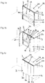
- Figures 1a, 1b and 1c show a piece of furniture 16, with a fixed part 20, two furniture walls 3 and two folding sliding doors 2. These two folding sliding doors 2 each have a first door leaf 2a and a second door leaf 2b, the two door leaves 2a, 2b via the folding door hinges 21 are foldable.
- the furniture 16 also has a receiving area 17 and two laterally arranged receiving shafts 22 or "pockets". It is therefore provided that the furniture 16 has a receiving area 17 for receiving components of a kitchen 18 (for example electrical devices such as stove, oven, etc.), a clothes storage device 19 (for example drawers, hangers, boxes, etc.) or the like.
- a kitchen 18 for example electrical devices such as stove, oven, etc.
- a clothes storage device 19 for example drawers, hangers, boxes, etc.
- the furniture 16 has at least one receiving shaft 22, which is preferably arranged laterally in or on the furniture 16 and in which the at least one folding sliding door 2 can be lowered.
- the receiving shaft 22 can therefore either be arranged on the outside of the furniture 16 or the receiving shaft 22 is formed in the furniture 16, for example by arranging an additional wall.
- the arrangements 1 (not visible) for guiding the folding sliding doors 2 are arranged in the receiving shafts 22 or, more precisely, on the furniture walls 3, so that the folding sliding doors 2 can be lowered into these receiving shafts 22.
- the two receiving shafts 22 have a clear width of 10 to 30 cm and / or a height of 100 to 250 cm and / or a depth of 60 to 100 cm.
- FIG. 1a The illustration shown corresponds to the parking position of the folding sliding doors 2 and those in FIG Figure 1c corresponds to the closed position of the folding sliding doors 2.
- the second door leaf 2b is in each case coupled to a carriage 23, the carriage 23 being displaceable along a carriage rail 24.
- This carriage rail 24 is arranged on the furniture 16 essentially transversely to the guide systems 4a, 4b (not visible).
- a web 30 is provided, which is either part of the carriage rail 24 or is designed as a separate component. The movement of the folding sliding doors 2 between the parking position and the closed position is thus made possible by the guide systems 4a, 4b and the carriage rail 24.
- the folding sliding doors 2 can therefore be moved into that position Figure 1b are moved, which can be seen from the folding sliding door 2 shown on the left.
- the folding sliding doors 2 are moved along the guides 5a, 5b (not visible) of the guide systems 4a, 4b.
- the folding sliding doors 2 are in the essentially coplanar position according to FIG Figure 1c brought.
- the door leaf 2b is moved with the aid of the carriage 23 along the carriage rail 24 until the closed position of the folding sliding doors 2 is reached, in which the two door leaves 2a, 2b are aligned essentially coplanar.
- the same sequence is followed in reverse order.
- Figure 2 shows an embodiment of the arrangement 1 for guiding a sliding door or folding sliding door 2 on a furniture wall 3.
- This arrangement 1 can therefore be used to insert a folding sliding door 2 along the furniture wall 3 into the receiving shafts 22, which in a piece of furniture 16 according to FIGS Figures 1a to 1c are intended to be moved in or out.
- a first guide system 4a to be fastened to the furniture wall 3 and a second guide system 4b to be fastened to the furniture wall 3 at a vertical distance 25 from the first guide system 4a are provided, the two guide systems 4a, 4b each having a guide 5a, 5b and one on the guide 5a, 5b have displaceably mounted guide bodies 6a, 6b.
- the arrangement 1 comprises a carrier 7 to which the sliding door or folding sliding door 2 - indicated by a dotted line - is to be attached and which is connected in a movement-coupled manner to the two guide bodies 6a, 6b of the guide systems 4a, 4b.
- the division of the carrier 7 into the three carrier sections 7a, 7b, 7c is also indicated by dashed lines.
- the carrier 7 is composed of at least three carrier sections 7a, 7b, 7c in the vertical direction, a first carrier section 7a with the guide body 6a of the first guide system 4a and a second carrier section 7b with the guide body 6b of the second guide system 4b is connected, and wherein a third support section 7c connects the first and second support sections 7a, 7b to one another.
- the arrangement 1 has a cable pull device for compensating a tilting moment KM of the carrier 7 or a sliding door or folding-sliding door 2 arranged thereon about a tilting axis KA by means of a restoring moment RM.
- the tilting axis KA is aligned horizontally.
- the cable device thus ensures that the sliding door or folding-sliding door 2 is guided in a stable manner in every position without causing a Tilting or, in the case of a guide on two guide systems 4a, 4b which are essentially aligned in parallel, tilting occurs.
- the cable device comprises two separate pull cables 11a, 11b, the pull cable 11a being arranged between the guide body 6a of the first guide system 4a and both ends 26, 27 of the guide 5a of the first guide system 4a and without connection to the second guide system 4b is formed, and that the pull rope 11b is arranged between the guide body 6b of the second guide system 4b and both ends 28, 29 of the guide 5b of the second guide system 4b and is designed without connection to the first guide system 4a.
- a synchronization device 13 is shown between the attack means 12a, 12b.
- each of the guide bodies 6a, 6b comprises at least one engagement means 12a, 12b for at least one pull rope 11a, 11b, and the engagement means 12a, 12b of the guide bodies 6a, 6b can be coupled via at least one synchronization device 13 separate from the carrier 7, whereby the at least one synchronization device 13 is designed to transmit a torque between the engagement means 12a, 12b of the guide bodies 6a, 6b.
- the ends of the pull cords 11a and 11b are respectively attached to the ends 26 and 27 and 28 and 29 of the guides 5a and 5b.
- the pull cables 11a and 11b are unwound by a certain amount and wound up again by the same amount at the same time, so that the number of turns remains essentially unchanged.
- the engagement means 12a, 12b are set in rotation about an axis of rotation. This The axis of rotation can take place either around a vertical axis or around a horizontal axis, depending on the mounting of the engagement means 12a, 12b on the guide bodies 6a, 6b.
- the means of attack 12a, 12b do not necessarily have to be storage and winding devices. It is only essential that the pull cables 11a, 11b are held taut between the ends 26, 27, 28, 29 of the guides 5a, 5b and the guide bodies 6a, 6b in every position of the guide bodies 6a, 6b relative to the guides 5a, 5b . In this way, the pull cables 11a, 11b can exert a force between the ends 26, 27, 28, 29 and the guide bodies 6a, 6b and thus provide a restoring moment RM to compensate for the tilting moment KM.
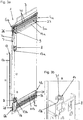
- Figure 3a shows the furniture wall 3 and the arrangement 1 according to Figure 2 in a perspective view.
- the support sections 7a, 7b each have an angle plate 8, which are used to connect the respective support sections 7a, 7b, 7c to one another.
- An interface 9 is shown, which is used to fasten the folding sliding door 2.
- the carrier 7 has at least two, preferably three, interfaces 9 for fastening the sliding door or folding-sliding door 2, the at least two interfaces 9 on different carrier sections 7a, 7b, 7c of the carrier 7 are arranged, preferably with at least one interface 9 being adjustable in the vertical direction.
- the synchronization device 13 is shown, which is composed of three synchronization sections 13a, 13b, 13c in the vertical direction, the three synchronization sections 13a, 13b, 13c being releasably connectable.
- the length l1 of the synchronization section 13c is between 5 and 20 mm, preferably 10mm, less than the clear width l2 between the two synchronization sections 13a and 13b.
- the passage openings 40 can be seen, which are used to fasten the two guide systems 4a, 4b to the furniture wall 3. It can be attached, for example, using screws.
- at least one of the synchronization sections 13a, 13b, 13c, preferably the third synchronization section 13c can be adapted in terms of its length. This ensures that the synchronization device 13 can be used for folding sliding doors 2 with different heights.
- FIG. 13 shows a detailed illustration of the area B according to FIG Figure 3a .
- the synchronization section 13b can be seen here.
- a sleeve 14 is displaceably mounted on the circumference of the synchronization section 13b, a spacer screw 31 being additionally arranged at the upper end of the synchronization section 13b.
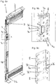
- Figure 4a shows the furniture wall 3 and the arrangement according to Figure 3a , wherein the synchronization section 13c has already been placed on the spacer screw 31. For this purpose, the synchronization section 13c was shifted in the horizontal direction and positioned on the spacer screw 31.
- Figure 4b and Figure 4c show a detailed representation of the area A and the area B according to FIG Figure 4a . It can be seen that an intermediate space 32 is formed between the synchronization sections 13a and 13c or 13b and 13c, the synchronization section 13c being adjusted in height by the spacer screw 31.
- the inner contour of the sleeve 14 is modeled on the outer contour of the synchronization sections 13a, 13b, 13c, so that the sleeve 14 can be displaced along these synchronization sections 13a, 13b, 13c. It is pointed out here that the assembly of the synchronization device 13 or the connection of the synchronization sections 13a, 13b, 13c from the front of the piece of furniture 16 is feasible. Only the guide bodies 6a, 6b and thus also the carrier 7 have to be in the position shown according to FIG Figure 4a be moved.
- FIGS 5a to 5c show the releasable connection between the synchronization sections 13b and 13c. It is pointed out here that the detachable connection between the synchronization sections 13a and 13c takes place analogously to this. The sleeve 14 is thus displaced in the direction of the synchronization section 13c until the frictional spring 33 of the sleeve 14 reaches the intermediate space 32 and engages in it. Provision is therefore made for the detachable connection of the synchronization sections 13a, 13b, 13c to take place via sleeves 14 which can be displaced in the vertical direction.
- Figure 6a shows the two carrier sections 7c, 7d of the carrier 7. It is thus provided that the third carrier section 7c has a fixed length l3 and optionally a fourth carrier section 7d is provided, which can be adjusted in length l4.
- the carrier 7 can thus be adapted to different heights of a folding sliding door 2.
- the upper angle plate 8 of the support section 7c in the illustration serves to connect to the support section 7a, it being provided that this support section 7c and the two angle plates 8 connected to it are preassembled.
- the angle plates 8 are riveted to the support section 7c via the rivets 41.
- the length l3 of the carrier section 7c is selected according to the smallest height of a folding sliding door 2, so that the carrier section 7d is not necessary for a folding sliding door 2 of this height.
- the carrier section 7d can be adapted accordingly in terms of its length l4 and connected to the carrier section 7c.
- the lower angle plate 8 of the support section 7c serves to connect to the upper angle plate 8 of the support section 7d.
- a further angle plate 8a is provided, which connects these two angle plates 8 to one another.
- slot nuts 34 are provided, which can be displaced in the grooves 35 of the support section 7d.
- the length l4 of the support section 7d can be adapted, whereby it is further ensured that the angle plates 8 can be fastened to the support section 7d.
- Figure 6b shows a sectional view with regard to the connection between the angle plate 8 and the support section 7d.
- the slot nuts 34 are pushed into the grooves 35 provided for this purpose in the support section 7d.
- the angle plates 8 are then pushed onto the support section 7d, so that the respective holes for connecting the angle plates 8 to the support section 7d are arranged one above the other.
- the countersunk screws 36 can then be screwed into these holes, so that a detachable plug-in and screw connection between the carrier section 7d and the angle plates 8 is achieved.
- the carrier 7 or the carrier sections 7a, 7b, 7c, 7d are essentially L-shaped in cross-section and / or have at least one recess 15 for receiving at least one synchronization device 13. Due to the substantially L-shaped design of the support section 7d, there is thus a flattened point 39, so that the assembly of the support section 7d is facilitated.
- Figure 7a shows the furniture wall 3 and the arrangement 1.
- Part of the carriage rail 24 can be seen, with a connecting piece 37 for the carriage rail 24 also being arranged on the support section 7a.
- the connection piece 37 is designed as a carrier.
- the carriage 23 is moved onto this connection piece 37 so that the door leaves 2a, 2b are aligned essentially parallel to one another.
- the two carrier sections 7c, 7d have already been connected to one another and can be connected to the two carrier sections 7a, 7b as a preassembled carrier 7.
- Figure 7b shows a detailed illustration of the area A of FIG Figure 7a .
- the assembly of the carrier 7 can also be carried out from the front of the furniture 16, provided that the guide bodies 6a, 6b are in the position according to FIG Figure 7a are moved.
- Figure 8a shows the carrier sections 7c, 7d in their position that can be assembled with the carrier sections 7a, 7b. This is also based on the Figure 8b can be seen, which is a more detailed view of area A of the Figure 8a indicates.
- the angle plates 8a are pushed into the angle plates 8 so that the support sections 7a, 7b, 7c, 7d or the angle plates 8 are releasably connected to one another via a plug connection.
- the countersunk screws 36 are then screwed into the holes provided for this purpose, so that a screw connection also takes place.
- Figures 9a to 9c show the releasably interconnected support sections 7a, 7b, 7c, 7d.
- Figure 9b shows a more precise representation of the area A of FIG Figure 9a
- Figure 9c shows a more detailed view of the plug and screw connection between the angle plates 8, 8a. It is provided for connecting the angle plates 8 to one another that the angle plate 8a is pushed into the angle plates 8 until the connectors 38 engage in the corresponding openings in the angle plates 8. The countersunk screws 36 are then screwed into the respective holes of the angle plates 8, so that a plug-in and screw connection results.
- Figure 10 shows the furniture wall 3 and the arrangement 1, the carrier 7 being designed according to an alternative embodiment.
- the carrier 7 here has a first carrier section 7a and a second carrier section 7b.
- the first support section 7a is connected in a movement-coupled manner to the guide body 6a of the first guide system 4a and the second support section 7b is connected in a movement-coupled manner to the guide body 6b of the second guide system 4b.
- An interface 9 for fastening the folding sliding door 2 is arranged on each of the carrier section 7a and the carrier section 7b.
- Figure 11a shows compared to Figure 10 in addition, the third support section 7c, which serves to connect the first 7a and second support section 7b to one another.
- Figure 11b shows the third support section 7c in a perspective view and Figure 11c shows the third carrier section 7c with the interface 9 in a sectional perspective.
- the support section 7c has a recess 15 for receiving the third synchronization section 13c.
- the interface 9 shown can be fastened to the support section 7c at different vertical positions with the aid of countersunk screws 36. This is achieved by the sliding nuts 34 which can be displaced in the grooves 35. The slot nuts 34 are thus shifted into the desired position and then the countersunk screws 36 are screwed through the interface 9 into the slot nuts 34 so that the interface 9 is fixed in the desired position.
- the interface 9 has a friction surface 42 on the side facing the carrier section 7c, which cooperates with the support section 7c. This results in an improved fastening of the interface 9 to the carrier section 7c.
- Figure 12 shows the assembled carrier 7, the carrier section 7c connecting the first carrier section 7a and the second carrier section 7b to one another.
- the arrangement 1 has at least one synchronization device 13, and the at least one synchronization device 13 is arranged between the guide bodies 6a, 6b of the guide systems 4a, 4b in a further method step, which is carried out before or after the third method step, wherein the at least two synchronization sections 13a, 13b, 13c are releasably connected. It is preferably provided that the carrier 7 and the at least one synchronization device 13 are moved in the horizontal direction for assembly.
Landscapes
- Engineering & Computer Science (AREA)
- Mechanical Engineering (AREA)
- Civil Engineering (AREA)
- Structural Engineering (AREA)
- Assembled Shelves (AREA)
- Extensible Doors And Revolving Doors (AREA)
- Support Devices For Sliding Doors (AREA)
- Cabinets, Racks, Or The Like Of Rigid Construction (AREA)
Claims (14)
- Dispositif (1) pour le guidage d'une porte coulissante ou d'une porte coulissante pliante (2) sur une paroi de meuble (3), avec- un premier système de guidage (4a) à fixer à la paroi de meuble (3) et un deuxième système de guidage (4b) à fixer à la paroi de meuble (3) à un écartement vertical (25) par rapport au premier système de guidage (4a), dans lequel les deux systèmes de guidage (4a, 4b) présentent chacun au moins une glissière (5a, 5b) et un corps de guidage (6a, 6b) logé de façon déplaçable sur la glissière (5a, 5b),- un support (7), sur lequel la porte coulissante ou la porte coulissante pliante (2) est à fixer et lequel est relié en étant couplé en mouvement aux deux corps de guidage (6a, 6b) des systèmes de guidage (4a, 4b), et
dans lequel le support (7) est composé dans le sens vertical de au moins deux tronçons de support (7a, 7b, 7c, 7d), dans lequel les au moins deux tronçons de support (7a, 7b, 7c, 7d) peuvent être reliés de façon détachable, caractérisé en ce que le dispositif (1) présente un dispositif à câble de traction pour compenser un couple de basculement (KM) du support (7) ou de la porte coulissante ou de la porte coulissante pliante (2), disposée dessus, autour d'un axe de basculement (KA) par un couple antagoniste (RM), dans lequel chacun des corps de guidage (6a, 6b) comprend au moins un moyen d'attaque (12a, 12b) pour au moins un câble de traction (11a, 11b), et les moyens d'attaque (12a, 12b) des corps de guidage (6a, 6b) peuvent être couplés par au moins un dispositif de synchronisation (13), séparé du support (7), du dispositif (1), dans lequel l'au moins un dispositif de synchronisation (13) est conçu pour transmettre un moment de rotation entre les moyens d'attaque (12a, 12b) des corps de guidage (6a, 6b). - Dispositif (1) selon la revendication 1, dans lequel la liaison détachable des tronçons de support prévus (7a, 7b, 7c, 7d) se fait par des tôles pliées (8, 8a) qui peuvent être reliées aux tronçons de support (7a, 7b, 7c, 7d), de préférence, par une liaison enfichable et / ou à vis.
- Dispositif (1) selon la revendication 1 ou 2, dans lequel le support (7) est composé dans le sens vertical d'au moins trois tronçons de support (7a, 7b, 7c, 7d), dans lequel un premier tronçon de support (7a) est relié au corps de guidage (6a) du premier système de guidage (4a) et un deuxième tronçon de support (7b) est relié au corps de guidage (6b) du deuxième système de guidage (4b), et dans lequel un troisième tronçon de support (7c) relie ensemble le premier (7a) et le deuxième tronçon de support (7c).
- Dispositif (1) selon la revendication 3, dans lequel le troisième tronçon de support (7c) a une longueur fixe (13) et, facultativement, un quatrième tronçon de support (7d) est prévu, qui peut être ajusté en longueur (14).
- Dispositif (1) selon l'une des revendications 1 à 4, dans lequel le support (7) présente au moins deux, de préférence trois, interfaces (9) pour la fixation de la porte coulissante ou de la porte coulissante pliante (2), dans lequel les au moins deux interfaces (9) sont disposées aux différents tronçons de support (7a, 7b, 7c, 7d) du support (7), dans lequel, de préférence, au moins une interface (9) est réglable dans le sens vertical.
- Dispositif (1) selon l'une des revendications 1 à 5, dans lequel le dispositif à câble de traction comprend au moins deux câbles de traction (11a, 11b) séparés l'un de l'autre, un premier (11a) de ces deux câbles de traction (11a, 11b) est disposé entre le corps de guidage (6a) du premier système de guidage (4a) et au moins une extrémité (26, 27) de la glissière (5a) du premier système de guidage (4a) et est formé sans liaison au deuxième système de guidage (4b), et un deuxième (11b) de ces deux câbles de traction (11a, 11b) est disposé entre le corps de guidage (6b) du deuxième système de guidage (4b) et au moins une extrémité (28, 29) de la glissière (5b) du deuxième système de guidage (4b) et est formé sans liaison au premier système de guidage (4a).
- Dispositif (1) selon la revendication 6, dans lequel l'au moins un dispositif de synchronisation (13) est composé, dans le sens vertical, d'au moins deux tronçons de synchronisation (13a, 13b, 13c), dans lequel les au moins deux tronçons de synchronisation (13a, 13b, 13c) peuvent être reliés de façon détachable, dans lequel, de préférence, la liaison détachable des tronçons de synchronisation (13a, 13b, 13c) se fait au moyen de manchons (14) déplaçables dans le sens vertical.
- Dispositif (1) selon la revendication 7, dans lequel au moins un des tronçons de synchronisation (13a, 13b, 13c) peut être ajusté en longueur.
- Dispositif (1) selon l'une des revendications 1 à 8, dans lequel le support (7) ou les tronçons de support (7a, 7b, 7c, 7d) sont conçus en section transversale essentiellement en forme de L, et / ou présentent au moins un évidement (15) pour loger au moins un dispositif de synchronisation (13), prévu le cas échéant.
- Meuble (16) avec au moins une paroi de meuble (3), au moins une porte coulissante ou une porte coulissante pliante (2), et au moins un dispositif (1) selon l'une des revendications 1 à 9, dans lequel le premier (4a) et deuxième système de guidage (4b) est fixé à l'au moins une paroi de meuble (3) et l'au moins une porte coulissante ou porte coulissante pliante (2) est fixée au support (7).
- Meuble (16) selon la revendication 10, dans lequel le meuble (16) présente une zone de logement (17) pour loger des éléments d'une cuisine (18), d'un dispositif de rangement de vêtements (19) ou similaires.
- Procédé de montage d'un dispositif (1) selon l'une des revendications 1 à 9 sur une paroi de meuble (3), dans lequel- à une première étape du procédé, le premier système de guidage (4a) ou le deuxième système de guidage (4b) est fixé à la paroi de meuble (3),- à une deuxième étape du procédé, l'autre système de guidage (4a, 4b) est fixé à la paroi de meuble (3) à un écartement vertical (25) par rapport au système de guidage (4a, 4b) fixé au cours de la première étape du procédé à la paroi de meuble (3), et- à une troisième étape du procédé, les corps de guidage (6a, 6b) des systèmes de guidage (4a, 4b) sont reliés ensemble par le support (7) en étant couplés en mouvement, dans lequel les au moins deux tronçons de support (7a, 7b, 7c, 7d) du support (7) sont reliés de façon détachable.
- Procédé selon la revendication 12, dans lequel l'au moins un dispositif de synchronisation (13), dans une autre étape du procédé qui est réalisée avant ou après la troisième étape du procédé, est disposé entre les corps de guidage (6a, 6b) des systèmes de guidage (4a, 4b), dans lequel les au moins deux tronçons de synchronisation (13a, 13b, 13c) sont reliés de façon détachable.
- Procédé selon la revendication 12 ou 13, dans lequel le support (7) et l'au moins un dispositif de synchronisation (13) sont déplacés dans le sens horizontal pour le montage.
Applications Claiming Priority (2)
| Application Number | Priority Date | Filing Date | Title |
|---|---|---|---|
| ATA50389/2017A AT519897B1 (de) | 2017-05-11 | 2017-05-11 | Anordnung zur Führung einer Schiebetür oder Falt-Schiebetür |
| PCT/AT2018/000036 WO2018204948A1 (fr) | 2017-05-11 | 2018-05-04 | Ensemble destiné à guider une porte coulissante ou une porte coulissante pliante |
Publications (2)
| Publication Number | Publication Date |
|---|---|
| EP3622148A1 EP3622148A1 (fr) | 2020-03-18 |
| EP3622148B1 true EP3622148B1 (fr) | 2021-07-28 |
Family
ID=62554902
Family Applications (1)
| Application Number | Title | Priority Date | Filing Date |
|---|---|---|---|
| EP18729538.1A Active EP3622148B1 (fr) | 2017-05-11 | 2018-05-04 | Ensemble destiné à guider une porte coulissante ou une porte coulissante pliante |
Country Status (8)
| Country | Link |
|---|---|
| US (1) | US10947763B2 (fr) |
| EP (1) | EP3622148B1 (fr) |
| JP (1) | JP6906635B2 (fr) |
| CN (1) | CN110709574B (fr) |
| AT (1) | AT519897B1 (fr) |
| ES (1) | ES2893112T3 (fr) |
| TW (1) | TWI666374B (fr) |
| WO (1) | WO2018204948A1 (fr) |
Cited By (1)
| Publication number | Priority date | Publication date | Assignee | Title |
|---|---|---|---|---|
| WO2025050149A1 (fr) | 2023-09-04 | 2025-03-13 | Julius Blum Gmbh | Procédé d'installation d'un profilé |
Families Citing this family (13)
| Publication number | Priority date | Publication date | Assignee | Title |
|---|---|---|---|---|
| AT519513B1 (de) * | 2017-01-13 | 2022-09-15 | Blum Gmbh Julius | Anordnung zur Führung einer Schiebetür oder Falt-Schiebetür an einer Möbelwand |
| AT519374B1 (de) * | 2017-01-13 | 2018-06-15 | Blum Gmbh Julius | Führungssystem zur Führung eines bewegbar gelagerten Möbelteiles |
| AT519903B1 (de) * | 2017-05-11 | 2022-09-15 | Blum Gmbh Julius | Schiene zur Führung eines Schlittens einer Möbeltüre |
| AT16936U1 (de) * | 2019-02-07 | 2020-12-15 | Blum Gmbh Julius | Vorrichtung zum Bewegen einer Schiebetür oder Falt-Schiebetür |
| TWI695113B (zh) * | 2019-03-05 | 2020-06-01 | 無界創新股份有限公司 | 收摺門之緊迫固定結構 |
| TWI683951B (zh) * | 2019-03-05 | 2020-02-01 | 無界創新股份有限公司 | 鉸鏈之連結結構 |
| WO2021003507A1 (fr) * | 2019-07-08 | 2021-01-14 | Julius Blum Gmbh | Dispositif pour guider une porte coulissante ou une porte accordéon sur une paroi de meuble |
| DE102019134567A1 (de) * | 2019-12-16 | 2021-06-17 | Miele & Cie. Kg | Einbaumodul für ein Haushaltgerät und Verfahren zum Einbau eines Haushaltgerätes in einen Möbelkorpus |
| AT17257U1 (de) * | 2019-12-19 | 2021-10-15 | Blum Gmbh Julius | Verfahren zur Montage einer Führungsanordnung für ein bewegbares Möbelteil |
| JP7366159B2 (ja) * | 2020-08-28 | 2023-10-20 | スガツネ工業株式会社 | 扉案内装置 |
| CN116615595A (zh) * | 2020-12-17 | 2023-08-18 | 优利思百隆有限公司 | 用于引导至少一个门扇的具有至少一个开关装置及至少一个传感器的引导系统 |
| CN113668972B (zh) * | 2021-09-30 | 2024-07-19 | 金湖畅途交通设备有限公司 | 一种气动塞拉门门泵结构 |
| AT526951B1 (de) * | 2023-09-07 | 2024-09-15 | Blum Gmbh Julius | Verfahren zur Montage eines Führungssystems zur Führung wenigstens eines bewegbar gelagerten Türflügels entlang einer Möbelwand |
Citations (1)
| Publication number | Priority date | Publication date | Assignee | Title |
|---|---|---|---|---|
| US20040046488A1 (en) * | 2002-09-10 | 2004-03-11 | Hogan Michael J. | Pocket door slide |
Family Cites Families (17)
| Publication number | Priority date | Publication date | Assignee | Title |
|---|---|---|---|---|
| US519513A (en) * | 1894-05-08 | Harry torchiani | ||
| AT390992B (de) * | 1987-07-23 | 1990-07-25 | Blum Gmbh Julius | Schiebetuerbeschlag |
| US5078461A (en) * | 1989-04-25 | 1992-01-07 | Herman Miller, Inc. | Cabinet with pocketing doors |
| CA1322571C (fr) * | 1988-08-24 | 1993-09-28 | Richard Oscar Rask | Montage de porte portefeuille |
| US4974912A (en) * | 1989-04-05 | 1990-12-04 | Standard Precision, Inc. | Pocket door suspension system |
| JPH0713423B2 (ja) * | 1989-04-05 | 1995-02-15 | 日本アキュライド株式会社 | ポケットドアのサスペンション装置 |
| DE19632427C2 (de) * | 1996-08-12 | 2002-02-21 | Webasto Tuersysteme Gmbh | Schwenkschiebetür für Fahrzeuge |
| JP3715958B2 (ja) * | 2002-10-18 | 2005-11-16 | 株式会社ムラコシ精工 | 折戸装置 |
| US7090318B2 (en) * | 2002-11-26 | 2006-08-15 | Tci Supply, Inc. | System for a sliding door with a camber |
| US20040100170A1 (en) * | 2002-11-26 | 2004-05-27 | Brown David Todd | System for a sliding door with a spacer block |
| US7959242B2 (en) * | 2003-06-02 | 2011-06-14 | Accuride International Inc. | Pocket door cabinet and slide assembly |
| WO2005059282A1 (fr) * | 2003-12-05 | 2005-06-30 | Atomlivintech Co., Ltd. | Dispositif d'ouverture/fermeture de porte coulissante |
| US20070159037A1 (en) * | 2006-01-10 | 2007-07-12 | Knape & Vogt Manufacturing Company | Hinge bracket for a pocket door |
| ITMI20061214A1 (it) * | 2006-06-23 | 2007-12-24 | Dada S P A | Armadio o mobile similare con sportelli pieghevoli e scorrevoli a scomparsa |
| US8424983B1 (en) * | 2012-02-10 | 2013-04-23 | Gary Strauss | Motorized upper and lower storage shelves |
| AT516567B1 (de) * | 2014-11-26 | 2018-01-15 | Blum Gmbh Julius | Anordnung aus einer Möbeltüre und einem Hohlraum |
| AT519513B1 (de) * | 2017-01-13 | 2022-09-15 | Blum Gmbh Julius | Anordnung zur Führung einer Schiebetür oder Falt-Schiebetür an einer Möbelwand |
-
2017
- 2017-05-11 AT ATA50389/2017A patent/AT519897B1/de active
-
2018
- 2018-05-03 TW TW107115015A patent/TWI666374B/zh active
- 2018-05-04 CN CN201880031073.3A patent/CN110709574B/zh active Active
- 2018-05-04 JP JP2019561805A patent/JP6906635B2/ja active Active
- 2018-05-04 EP EP18729538.1A patent/EP3622148B1/fr active Active
- 2018-05-04 ES ES18729538T patent/ES2893112T3/es active Active
- 2018-05-04 WO PCT/AT2018/000036 patent/WO2018204948A1/fr not_active Ceased
-
2019
- 2019-10-16 US US16/654,671 patent/US10947763B2/en active Active
Patent Citations (1)
| Publication number | Priority date | Publication date | Assignee | Title |
|---|---|---|---|---|
| US20040046488A1 (en) * | 2002-09-10 | 2004-03-11 | Hogan Michael J. | Pocket door slide |
Cited By (2)
| Publication number | Priority date | Publication date | Assignee | Title |
|---|---|---|---|---|
| WO2025050149A1 (fr) | 2023-09-04 | 2025-03-13 | Julius Blum Gmbh | Procédé d'installation d'un profilé |
| TWI898811B (zh) * | 2023-09-04 | 2025-09-21 | 奧地利商朱利葉斯百隆股份有限公司 | 用於安裝型材的方法、用於支承結構的型材以及具有該型材的傢俱 |
Also Published As
| Publication number | Publication date |
|---|---|
| JP6906635B2 (ja) | 2021-07-21 |
| TW201905312A (zh) | 2019-02-01 |
| AT519897A1 (de) | 2018-11-15 |
| ES2893112T3 (es) | 2022-02-08 |
| EP3622148A1 (fr) | 2020-03-18 |
| CN110709574A (zh) | 2020-01-17 |
| WO2018204948A1 (fr) | 2018-11-15 |
| TWI666374B (zh) | 2019-07-21 |
| JP2020519789A (ja) | 2020-07-02 |
| CN110709574B (zh) | 2021-07-06 |
| AT519897B1 (de) | 2020-09-15 |
| US10947763B2 (en) | 2021-03-16 |
| US20200048947A1 (en) | 2020-02-13 |
Similar Documents
| Publication | Publication Date | Title |
|---|---|---|
| EP3622148B1 (fr) | Ensemble destiné à guider une porte coulissante ou une porte coulissante pliante | |
| EP3568561B1 (fr) | Dispositif pour guider une porte coulissante ou une porte coulissante pliante sur un mur de meuble | |
| DE68913079T2 (de) | Befestiger für Dachhimmel und Sonnenblende. | |
| EP3622149B1 (fr) | Rail de guidage d'un chariot d'une porte de meuble | |
| EP3997293B1 (fr) | Dispositif pour guider une porte coulissante ou une porte accordéon sur une paroi de meuble | |
| EP2992156B1 (fr) | Système de guidage d'une porte coulissante, porte coulissante et meuble | |
| EP3928392A1 (fr) | Agencement de charnière pour une armoire électrique et procédé correspondant | |
| DE102020102207A1 (de) | Vorrichtung zum Bewegen einer Schiebetür oder Falt-Schiebetür | |
| EP3467240B1 (fr) | Procédé de montage en position finale d'un support de poignée de porte et ensemble de fixation de support de poignée de porte | |
| DE69102188T2 (de) | Verbindungseinrichtung zwischen einem unteren Profil des Fahrzeugtürfensters und einem beweglichen Profil des Fensterhebers sowie eine mit dieser Einrichtung ausgestattete Fahrzeugtür. | |
| DE202008015265U1 (de) | Fenster | |
| DE202016106504U1 (de) | Montagewerkzeug für die Montage einer Schaltschranktür an einem Schaltschrankgehäuse und eine entsprechende Schaltschrankanordnung | |
| EP3860400B1 (fr) | Dispositif de fixation servant à fixer un panneau d'un tiroir sur un châssis | |
| EP2837763B1 (fr) | Butée de porte coulissante et mobilier | |
| DE202011005605U1 (de) | Faltbares Fensterladensystem und Führungseinrichtung für ein derartiges System | |
| EP0092104A1 (fr) | Châssis comprenant des cadres pour cartes déplaçables au moyen de guides latéraux coulissants | |
| DE2928118C2 (de) | Zur nebeneinander gereihten Befestigung an einer Montageschiene ausgebildetes Schalttafelelement, insbesondere Sicherungsautomat oder Trennschalter | |
| EP2653074B1 (fr) | Système de crochet mural pour suspendre des vêtements, notamment dans un train | |
| DE29601055U1 (de) | Deckengelenkrolladen | |
| EP2921786B1 (fr) | Porte d'appareil ménager dotée d'un élément de liaison comprenant un élément de centrage, appareil ménager doté d'une telle porte et procédé de montage d'une porte | |
| DE19954673B4 (de) | Blechschrank mit einem Korpus aus Blechpaneelen und einem diese aneinander festlegenden Verbindungselement | |
| EP0410477A2 (fr) | Dispositif de connexion pour des ressorts | |
| EP2684504B1 (fr) | Paquet de baguettes | |
| EP2696017B1 (fr) | Dispositif destiné à orienter des fenêtres et des portes | |
| DE102024107077A1 (de) | Verfahren zur Erleichterung der Montage und/oder Einstellung einer Antriebsvorrichtung zur verschiebbaren Betätigung eines beweglichen Schiebeflügels oder Hebe-Schiebeflügels eines Fensters oder einer Tür |
Legal Events
| Date | Code | Title | Description |
|---|---|---|---|
| STAA | Information on the status of an ep patent application or granted ep patent |
Free format text: STATUS: UNKNOWN |
|
| STAA | Information on the status of an ep patent application or granted ep patent |
Free format text: STATUS: THE INTERNATIONAL PUBLICATION HAS BEEN MADE |
|
| PUAI | Public reference made under article 153(3) epc to a published international application that has entered the european phase |
Free format text: ORIGINAL CODE: 0009012 |
|
| STAA | Information on the status of an ep patent application or granted ep patent |
Free format text: STATUS: REQUEST FOR EXAMINATION WAS MADE |
|
| 17P | Request for examination filed |
Effective date: 20191014 |
|
| AK | Designated contracting states |
Kind code of ref document: A1 Designated state(s): AL AT BE BG CH CY CZ DE DK EE ES FI FR GB GR HR HU IE IS IT LI LT LU LV MC MK MT NL NO PL PT RO RS SE SI SK SM TR |
|
| STAA | Information on the status of an ep patent application or granted ep patent |
Free format text: STATUS: EXAMINATION IS IN PROGRESS |
|
| 17Q | First examination report despatched |
Effective date: 20200616 |
|
| GRAP | Despatch of communication of intention to grant a patent |
Free format text: ORIGINAL CODE: EPIDOSNIGR1 |
|
| STAA | Information on the status of an ep patent application or granted ep patent |
Free format text: STATUS: GRANT OF PATENT IS INTENDED |
|
| INTG | Intention to grant announced |
Effective date: 20210421 |
|
| GRAS | Grant fee paid |
Free format text: ORIGINAL CODE: EPIDOSNIGR3 |
|
| GRAA | (expected) grant |
Free format text: ORIGINAL CODE: 0009210 |
|
| STAA | Information on the status of an ep patent application or granted ep patent |
Free format text: STATUS: THE PATENT HAS BEEN GRANTED |
|
| AK | Designated contracting states |
Kind code of ref document: B1 Designated state(s): AL AT BE BG CH CY CZ DE DK EE ES FI FR GB GR HR HU IE IS IT LI LT LU LV MC MK MT NL NO PL PT RO RS SE SI SK SM TR |
|
| REG | Reference to a national code |
Ref country code: GB Ref legal event code: FG4D Free format text: NOT ENGLISH |
|
| REG | Reference to a national code |
Ref country code: CH Ref legal event code: EP |
|
| REG | Reference to a national code |
Ref country code: DE Ref legal event code: R096 Ref document number: 502018006332 Country of ref document: DE |
|
| REG | Reference to a national code |
Ref country code: AT Ref legal event code: REF Ref document number: 1414879 Country of ref document: AT Kind code of ref document: T Effective date: 20210815 |
|
| REG | Reference to a national code |
Ref country code: IE Ref legal event code: FG4D Free format text: LANGUAGE OF EP DOCUMENT: GERMAN |
|
| REG | Reference to a national code |
Ref country code: LT Ref legal event code: MG9D |
|
| REG | Reference to a national code |
Ref country code: NL Ref legal event code: MP Effective date: 20210728 |
|
| PG25 | Lapsed in a contracting state [announced via postgrant information from national office to epo] |
Ref country code: NO Free format text: LAPSE BECAUSE OF FAILURE TO SUBMIT A TRANSLATION OF THE DESCRIPTION OR TO PAY THE FEE WITHIN THE PRESCRIBED TIME-LIMIT Effective date: 20211028 Ref country code: PT Free format text: LAPSE BECAUSE OF FAILURE TO SUBMIT A TRANSLATION OF THE DESCRIPTION OR TO PAY THE FEE WITHIN THE PRESCRIBED TIME-LIMIT Effective date: 20211129 Ref country code: NL Free format text: LAPSE BECAUSE OF FAILURE TO SUBMIT A TRANSLATION OF THE DESCRIPTION OR TO PAY THE FEE WITHIN THE PRESCRIBED TIME-LIMIT Effective date: 20210728 Ref country code: BG Free format text: LAPSE BECAUSE OF FAILURE TO SUBMIT A TRANSLATION OF THE DESCRIPTION OR TO PAY THE FEE WITHIN THE PRESCRIBED TIME-LIMIT Effective date: 20211028 Ref country code: LT Free format text: LAPSE BECAUSE OF FAILURE TO SUBMIT A TRANSLATION OF THE DESCRIPTION OR TO PAY THE FEE WITHIN THE PRESCRIBED TIME-LIMIT Effective date: 20210728 Ref country code: RS Free format text: LAPSE BECAUSE OF FAILURE TO SUBMIT A TRANSLATION OF THE DESCRIPTION OR TO PAY THE FEE WITHIN THE PRESCRIBED TIME-LIMIT Effective date: 20210728 Ref country code: SE Free format text: LAPSE BECAUSE OF FAILURE TO SUBMIT A TRANSLATION OF THE DESCRIPTION OR TO PAY THE FEE WITHIN THE PRESCRIBED TIME-LIMIT Effective date: 20210728 Ref country code: FI Free format text: LAPSE BECAUSE OF FAILURE TO SUBMIT A TRANSLATION OF THE DESCRIPTION OR TO PAY THE FEE WITHIN THE PRESCRIBED TIME-LIMIT Effective date: 20210728 Ref country code: HR Free format text: LAPSE BECAUSE OF FAILURE TO SUBMIT A TRANSLATION OF THE DESCRIPTION OR TO PAY THE FEE WITHIN THE PRESCRIBED TIME-LIMIT Effective date: 20210728 |
|
| REG | Reference to a national code |
Ref country code: ES Ref legal event code: FG2A Ref document number: 2893112 Country of ref document: ES Kind code of ref document: T3 Effective date: 20220208 |
|
| PG25 | Lapsed in a contracting state [announced via postgrant information from national office to epo] |
Ref country code: PL Free format text: LAPSE BECAUSE OF FAILURE TO SUBMIT A TRANSLATION OF THE DESCRIPTION OR TO PAY THE FEE WITHIN THE PRESCRIBED TIME-LIMIT Effective date: 20210728 Ref country code: LV Free format text: LAPSE BECAUSE OF FAILURE TO SUBMIT A TRANSLATION OF THE DESCRIPTION OR TO PAY THE FEE WITHIN THE PRESCRIBED TIME-LIMIT Effective date: 20210728 Ref country code: GR Free format text: LAPSE BECAUSE OF FAILURE TO SUBMIT A TRANSLATION OF THE DESCRIPTION OR TO PAY THE FEE WITHIN THE PRESCRIBED TIME-LIMIT Effective date: 20211029 |
|
| PG25 | Lapsed in a contracting state [announced via postgrant information from national office to epo] |
Ref country code: DK Free format text: LAPSE BECAUSE OF FAILURE TO SUBMIT A TRANSLATION OF THE DESCRIPTION OR TO PAY THE FEE WITHIN THE PRESCRIBED TIME-LIMIT Effective date: 20210728 |
|
| REG | Reference to a national code |
Ref country code: DE Ref legal event code: R097 Ref document number: 502018006332 Country of ref document: DE |
|
| PG25 | Lapsed in a contracting state [announced via postgrant information from national office to epo] |
Ref country code: SM Free format text: LAPSE BECAUSE OF FAILURE TO SUBMIT A TRANSLATION OF THE DESCRIPTION OR TO PAY THE FEE WITHIN THE PRESCRIBED TIME-LIMIT Effective date: 20210728 Ref country code: SK Free format text: LAPSE BECAUSE OF FAILURE TO SUBMIT A TRANSLATION OF THE DESCRIPTION OR TO PAY THE FEE WITHIN THE PRESCRIBED TIME-LIMIT Effective date: 20210728 Ref country code: RO Free format text: LAPSE BECAUSE OF FAILURE TO SUBMIT A TRANSLATION OF THE DESCRIPTION OR TO PAY THE FEE WITHIN THE PRESCRIBED TIME-LIMIT Effective date: 20210728 Ref country code: EE Free format text: LAPSE BECAUSE OF FAILURE TO SUBMIT A TRANSLATION OF THE DESCRIPTION OR TO PAY THE FEE WITHIN THE PRESCRIBED TIME-LIMIT Effective date: 20210728 Ref country code: CZ Free format text: LAPSE BECAUSE OF FAILURE TO SUBMIT A TRANSLATION OF THE DESCRIPTION OR TO PAY THE FEE WITHIN THE PRESCRIBED TIME-LIMIT Effective date: 20210728 Ref country code: AL Free format text: LAPSE BECAUSE OF FAILURE TO SUBMIT A TRANSLATION OF THE DESCRIPTION OR TO PAY THE FEE WITHIN THE PRESCRIBED TIME-LIMIT Effective date: 20210728 |
|
| PLBE | No opposition filed within time limit |
Free format text: ORIGINAL CODE: 0009261 |
|
| STAA | Information on the status of an ep patent application or granted ep patent |
Free format text: STATUS: NO OPPOSITION FILED WITHIN TIME LIMIT |
|
| 26N | No opposition filed |
Effective date: 20220429 |
|
| REG | Reference to a national code |
Ref country code: BE Ref legal event code: MM Effective date: 20220531 |
|
| GBPC | Gb: european patent ceased through non-payment of renewal fee |
Effective date: 20220504 |
|
| PG25 | Lapsed in a contracting state [announced via postgrant information from national office to epo] |
Ref country code: MC Free format text: LAPSE BECAUSE OF FAILURE TO SUBMIT A TRANSLATION OF THE DESCRIPTION OR TO PAY THE FEE WITHIN THE PRESCRIBED TIME-LIMIT Effective date: 20210728 Ref country code: LU Free format text: LAPSE BECAUSE OF NON-PAYMENT OF DUE FEES Effective date: 20220504 |
|
| PG25 | Lapsed in a contracting state [announced via postgrant information from national office to epo] |
Ref country code: IE Free format text: LAPSE BECAUSE OF NON-PAYMENT OF DUE FEES Effective date: 20220504 Ref country code: FR Free format text: LAPSE BECAUSE OF NON-PAYMENT OF DUE FEES Effective date: 20220531 |
|
| PG25 | Lapsed in a contracting state [announced via postgrant information from national office to epo] |
Ref country code: GB Free format text: LAPSE BECAUSE OF NON-PAYMENT OF DUE FEES Effective date: 20220504 Ref country code: BE Free format text: LAPSE BECAUSE OF NON-PAYMENT OF DUE FEES Effective date: 20220531 |
|
| P01 | Opt-out of the competence of the unified patent court (upc) registered |
Effective date: 20230523 |
|
| PG25 | Lapsed in a contracting state [announced via postgrant information from national office to epo] |
Ref country code: MK Free format text: LAPSE BECAUSE OF FAILURE TO SUBMIT A TRANSLATION OF THE DESCRIPTION OR TO PAY THE FEE WITHIN THE PRESCRIBED TIME-LIMIT Effective date: 20210728 Ref country code: CY Free format text: LAPSE BECAUSE OF FAILURE TO SUBMIT A TRANSLATION OF THE DESCRIPTION OR TO PAY THE FEE WITHIN THE PRESCRIBED TIME-LIMIT Effective date: 20210728 |
|
| PG25 | Lapsed in a contracting state [announced via postgrant information from national office to epo] |
Ref country code: HU Free format text: LAPSE BECAUSE OF FAILURE TO SUBMIT A TRANSLATION OF THE DESCRIPTION OR TO PAY THE FEE WITHIN THE PRESCRIBED TIME-LIMIT; INVALID AB INITIO Effective date: 20180504 |
|
| PG25 | Lapsed in a contracting state [announced via postgrant information from national office to epo] |
Ref country code: MT Free format text: LAPSE BECAUSE OF FAILURE TO SUBMIT A TRANSLATION OF THE DESCRIPTION OR TO PAY THE FEE WITHIN THE PRESCRIBED TIME-LIMIT Effective date: 20210728 |
|
| PGFP | Annual fee paid to national office [announced via postgrant information from national office to epo] |
Ref country code: DE Payment date: 20250528 Year of fee payment: 8 |
|
| PGFP | Annual fee paid to national office [announced via postgrant information from national office to epo] |
Ref country code: ES Payment date: 20250611 Year of fee payment: 8 |
|
| PGFP | Annual fee paid to national office [announced via postgrant information from national office to epo] |
Ref country code: IT Payment date: 20250522 Year of fee payment: 8 |
|
| PGFP | Annual fee paid to national office [announced via postgrant information from national office to epo] |
Ref country code: CH Payment date: 20250601 Year of fee payment: 8 |
|
| PGFP | Annual fee paid to national office [announced via postgrant information from national office to epo] |
Ref country code: AT Payment date: 20250528 Year of fee payment: 8 |
|
| PGFP | Annual fee paid to national office [announced via postgrant information from national office to epo] |
Ref country code: TR Payment date: 20250425 Year of fee payment: 8 |