EP3622334B1 - Affichage diffractif, élément de guidage de lumière et son projecteur, et procédé d'affichage d'image - Google Patents
Affichage diffractif, élément de guidage de lumière et son projecteur, et procédé d'affichage d'image Download PDFInfo
- Publication number
- EP3622334B1 EP3622334B1 EP18798173.3A EP18798173A EP3622334B1 EP 3622334 B1 EP3622334 B1 EP 3622334B1 EP 18798173 A EP18798173 A EP 18798173A EP 3622334 B1 EP3622334 B1 EP 3622334B1
- Authority
- EP
- European Patent Office
- Prior art keywords
- coupling
- gratings
- grating
- image
- lightguide
- Prior art date
- Legal status (The legal status is an assumption and is not a legal conclusion. Google has not performed a legal analysis and makes no representation as to the accuracy of the status listed.)
- Active
Links
Images


Classifications
-
- G—PHYSICS
- G02—OPTICS
- G02B—OPTICAL ELEMENTS, SYSTEMS OR APPARATUS
- G02B5/00—Optical elements other than lenses
- G02B5/18—Diffraction gratings
- G02B5/1814—Diffraction gratings structurally combined with one or more further optical elements, e.g. lenses, mirrors, prisms or other diffraction gratings
- G02B5/1819—Plural gratings positioned on the same surface, e.g. array of gratings
-
- G—PHYSICS
- G02—OPTICS
- G02B—OPTICAL ELEMENTS, SYSTEMS OR APPARATUS
- G02B27/00—Optical systems or apparatus not provided for by any of the groups G02B1/00 - G02B26/00, G02B30/00
- G02B27/0081—Optical systems or apparatus not provided for by any of the groups G02B1/00 - G02B26/00, G02B30/00 with means for altering, e.g. enlarging, the entrance or exit pupil
-
- G—PHYSICS
- G02—OPTICS
- G02B—OPTICAL ELEMENTS, SYSTEMS OR APPARATUS
- G02B27/00—Optical systems or apparatus not provided for by any of the groups G02B1/00 - G02B26/00, G02B30/00
- G02B27/42—Diffraction optics, i.e. systems including a diffractive element being designed for providing a diffractive effect
- G02B27/4272—Diffraction optics, i.e. systems including a diffractive element being designed for providing a diffractive effect having plural diffractive elements positioned sequentially along the optical path
-
- G—PHYSICS
- G02—OPTICS
- G02B—OPTICAL ELEMENTS, SYSTEMS OR APPARATUS
- G02B5/00—Optical elements other than lenses
- G02B5/18—Diffraction gratings
- G02B5/1814—Diffraction gratings structurally combined with one or more further optical elements, e.g. lenses, mirrors, prisms or other diffraction gratings
- G02B5/1819—Plural gratings positioned on the same surface, e.g. array of gratings
- G02B5/1823—Plural gratings positioned on the same surface, e.g. array of gratings in an overlapping or superposed manner
-
- G—PHYSICS
- G02—OPTICS
- G02B—OPTICAL ELEMENTS, SYSTEMS OR APPARATUS
- G02B27/00—Optical systems or apparatus not provided for by any of the groups G02B1/00 - G02B26/00, G02B30/00
- G02B27/01—Head-up displays
- G02B27/0101—Head-up displays characterised by optical features
- G02B2027/0112—Head-up displays characterised by optical features comprising device for genereting colour display
-
- G—PHYSICS
- G02—OPTICS
- G02B—OPTICAL ELEMENTS, SYSTEMS OR APPARATUS
- G02B27/00—Optical systems or apparatus not provided for by any of the groups G02B1/00 - G02B26/00, G02B30/00
- G02B27/01—Head-up displays
- G02B27/0101—Head-up displays characterised by optical features
- G02B2027/0123—Head-up displays characterised by optical features comprising devices increasing the field of view
-
- G—PHYSICS
- G02—OPTICS
- G02B—OPTICAL ELEMENTS, SYSTEMS OR APPARATUS
- G02B27/00—Optical systems or apparatus not provided for by any of the groups G02B1/00 - G02B26/00, G02B30/00
- G02B27/01—Head-up displays
- G02B27/017—Head mounted
- G02B27/0172—Head mounted characterised by optical features
Definitions
- the invention relates to diffractive display technology used in personal microdisplays, such as near-to-eye displays (NEDs) or other head mounted displays (HMDs).
- NEDs near-to-eye displays
- HMDs head mounted displays
- the invention relates to waveguides used in augmented reality (AR) NEDs or HMDs.
- AR augmented reality
- the maximum field of view (FOV) of a single lightguide with 2D exit pupil expansion (EPE) depends on the lightguide refractive and the wavelength band of projected light. When wavelength band is 460 - 630 nm and lightguide refractive index is 2.0, the maximum FOV is around 33-35 degrees.
- typical approach is to use multiple lightguides. As conventional microdisplay projectors produce only a single exit pupil, the in-coupling gratings of the lightguides are typically laterally coincident and stacked on top of each other. With stacked in-couplers, the in-coupling process is not well controlled.
- the first lightguide supports entire FOV with blue wavelengths while with red wavelengths only a small part of FOV is in-coupled into the lightguide.
- the back diffracted light can couple to preceding lightguides and cause ghost images.
- Some conventional lightguides utilize three different light guides to obtain red, green and blue image channels and are capable of achieving a FOV of approximately 35 degrees. These lightguides have the drawback of being limited in resolution and/or in wavelength band.
- US 2014/218801 discloses a color projection display wherein a first range of file angles and second range of field angles are coupled into and guided in different waveguide layers with in-coupling gratings.
- the waveguide layers have the same or mirrored geometry, resulting in the in-coupling gratings being aligned with each other or positioned far from each, respectively. These arrangements are not optimal as concerns optical coupling efficiency and quality and size requirements.
- US 2006/132914 discloses another known waveguide arrangement with two in-coupling gratings in some embodiments thereof.
- US2016/327789 discloses a multi-pupil lightguide element for a diffractive personal display.
- US2016/231478 discloses a wearable display system.
- Particular aims include providing an extended-FOV lightguide element and extended FOV image projector, which can be combined to form a functional personal display.
- Secondary aims are to provide technology that allows decreasing device size, at least in proportion to the FOV achievable, and technology that allows for full color reproduction.
- the invention is based on splitting the FOV of the total image into partial FOVs (image segments) that are directed to a diffractive waveguide element through at least two different pupils, and designing the element in such a way that the partial FOVs are recombined into the total image viewable by a user.
- a novel multi-pupil waveguide element and a multi-pupil projector as described below are provided.
- One aspect of the invention is directed to a multi-pupil lightguide element according to claim 1.
- the diffractive out-coupling means of the multi-pupil lightguide element may comprise at least two out-coupling gratings laterally overlapping each other on the lightguide means.
- the at least two out-coupling gratings are optically associated with at least two in-coupling gratings, respectively, for reproducing said image from said image segments.
- the optical association can be implemented by incorporating the gratings on different lightguide layers, which together form said lightguide means, and typically by additionally providing exit pupil expander gratings which optically connect the in-couplers with the respective out-couplers in the different layers.
- the present personal display device comprises the multi-pupil lightguide element of claim 1 for producing an image viewable by the naked eye on the out-coupling means thereof, and a multi-pupil projector capable of projecting at least two different image segments of said image on said at least two in-coupling gratings.
- the segments are guided on at least partially different lateral positions of the lightguide element so that the FOV of the total image formed by device is larger than the FOV of any of the segments alone.
- the multi-pupil projector for a diffractive personal display comprises at least one display element for displaying an image, at least two exit pupils, and optical means for projecting at least two different segments of said image to said at least two exit pupils, respectively.
- the display element further comprises a non-polarized light source and means for utilizing two different polarization states of said light source for projecting said image segments to said exit pupils.
- Another aspect of the invention is directed to the method for displaying an image on a personal display device according to claim 15.
- the present use comprises using of multiple laterally displaced in-coupling gratings in a lightguide-based display element of a personal display for expanding the field of view of the personal display.
- the invention offers significant benefits over the prior art.
- the FOV of the waveguide is split instead of splitting the wavelength band.
- the total FOV can be increased significantly. This is because each exit pupil of the multi-pupil projector contains a part of the entire FOV.
- the entire FOV is then obtained using lightguides whose exit pupils (out-coupling gratings) are spatially overlapping. Also, because the exit pupils of the projector are spatially separated, it is possible to use spatially separated, i.e. displaced, in-coupling gratings in the lightguides.
- each lightguide contains a well-defined light spectrum with a well-defined FOV, which makes the lightguide optimization process easy and straightforward, in particular compared with wavelength band splitting -based approaches.
- Splitting the FOV to two optical paths in the system also allows for decreasing the size of the projector compared with full-FOV projectors, because its optical components, like beam splitters and illumination optics can be smaller.
- LCOS based multi-pupil projectors can be designed so that both polarization states of incident illumination are utilized, which makes it more energy efficient than conventional projectors that operate only with a single polarization state.
- the lightguide means comprise at least two lightguides stacked on top of each other.
- Each in-coupling grating and associated out-coupling grating is arranged on one of the waveguides, respectively, whereby light can propagate between via total internal reflections of the waveguide.
- planar or nearly planar waveguides are used.
- At least two exit pupil expander (EPE) gratings associated with the in-coupling gratings and out-coupling gratings, respectively, for extending the exit pupil of the element.
- the EPE gratings are arranged optically between the in- and out-coupling gratings, whereby their position, shape and grating line configuration, including orientation, is suitable to carry out exit pupil expansion.
- an EPE is provided only for some in-coupling gratings.
- the in-coupling gratings and exit pupil expander gratings are located such that a first in-coupling grating associated with a first exit pupil expander laterally overlaps with a second exit pupil expander associated with a second in-coupling grating.
- a first in-coupling grating associated with a first exit pupil expander laterally overlaps with a second exit pupil expander associated with a second in-coupling grating.
- the element comprises a first in-coupling grating and associated exit pupil expander grating pair and a second in-coupling grating and associated exit pupil expander grating pair, which is essentially mirror-symmetrically positioned on the lightguide means with respect to the first pair along at least one symmetry axis.
- the pairs are manufactured on different lightguides and then stacked so that the symmetry condition is fulfilled.
- the exit pupil expander gratings associated with different in-coupling gratings and out-coupling gratings are essentially aligned with each other.
- the in-coupling gratings can be positioned at different distances from respective EPE gratings so that they are laterally displaced but still optically coupled with the EPEs.
- the element is adapted to reproduce an image with a larger field-of-view on the out-coupling means than the field-of-view of any of the image segments presented on the in-coupling gratings.
- the elements acts as a FOV expander.
- the out-coupling gratings comprise grating lines oriented in the horizontal direction.
- they can also be placed in the vertical direction, whereby some undesired optical effects can be avoided. Both configurations are exemplified later in this document.
- the projector comprises a single display panel whose different zones are utilized for producing said different image segments. That is, no separate panels are needed for each separate segment (although separate panels can also be employed).
- the projector is adapted to produce the image on the display panel such that the image segments are in a laterally shifted configuration in at least one lateral dimension of the display panel, the segments optionally being separated by a black separating zone for preventing cross-talk between the segments on projector optics and/or the multi-pupil lightguide element.
- the optical axes of imaging optics for each segment are also preferably laterally shifted so that the black separating zone remains in the fringe area of the optical plane.
- the projector comprises a plurality of display panels that are utilized for producing the different image segments.
- This embodiment is particularly suitable for lightguide element configurations where the in-coupling gratings of different image segments are located far from each other.
- differently polarized light is fed to the different exit pupils.
- polarization can be carried out in the light source level, between the light source and the display panel, and/or between the display panel and exit pupils.
- the display element of the projector comprises a liquid crystal on silicon (LCOS) display panel or the like and an illumination system comprising at least two polarizing beam splitters arranged in sequence for utilizing two different polarization states of light for projecting said at least two different image segments.
- the display element may comprise two successive beam splitters, such as beam splitter cubes or plates, having perpendicular polarization orientations.
- the optics may comprise two successive beam splitters, such as beam splitter cubes or plates, having the same polarization orientation and a half-wavelength waveplate arranged optically between the beam splitters.
- the different image segments produced by the projector and directed to the lightguide element carry a different field-of-view of the total image.
- the different image segments are guided on different lightguide layers stacked on top of each other and comprising the in-coupling gratings and out-coupling gratings, respectively.
- the total FOV formed by the stack is arranged to be larger than any of the partial FOVs carried by the segments.
- Gratings being "overlapping" means that at least some portions of the gratings are laterally aligned with each other in the lightguide means. Overlapping gratings may also be entirely aligned, i.e. have the same shape and positioned in the same location.
- Gratings being "displaced" from each other means that they are not overlapping at least at portions thereof to which the image segments are projected.
- Multi-pupil projector means an image source that is capable of presenting a plurality of image segments on a plurality of exit pupils thereof in a suitably collimated beam of light for a diffractive in-coupling grating.
- a "multi-pupil lightguide element” is an element having a plurality of in-coupling gratings capable of receiving such light beams for coupling the image segments to the lightguide means for guiding to the out-coupling gratings for recombination of the image and viewing.
- Lightguide means refers in particular to a stack of diffractive lightguides adapted to in-couple, guide and out-couple the different image segments.
- diffractive lightguide arrangements are not excluded in the present concept.
- personal display refers in particular to NEDs and other kinds of HMDs, and HUDs (head-up displays).
- a multi-pupil diffractive display element and a multi-pupil projector therefor are described. These components can be used to form a functional lightguide based diffractive NED.
- the described embodiments exemplify how the FOV of the projector can be divided into multiple parts such that each pupil contains one part of the entire FOV, and how a functional NED with full FOV is obtained by combining the FOV parts by lightguides whose exit pupils are spatially overlapping.
- the projector comprises one or more display elements, at least two exit pupils and projection optics to guide different image segments displayed on the display panels to different exit pupils.
- the image-presenting portion is divided into several parts for different image segments.
- Each display part has its own projection optics unit and an exit pupil.
- the exit pupils are filled with collimated light.
- the display element(s) may comprise e.g. a liquid crystal display (LCD) panel(s), liquid crystal on silicon (LCOS) panel(s) or organic light emitting diode (OLED) panel(s), and also digital light processing (DLP) devices or digital micromirror devices (DMDs) may be employed. These are all referred to as "microdisplays”.
- LCD liquid crystal display
- LCOS liquid crystal on silicon
- OLED organic light emitting diode
- DLP digital light processing
- DMDs digital micromirror devices
- the image to be displayed is presented either on a single microdisplay panel or on two or more separate microdisplay panels. If a single panel is used, different image segments are displayed on different sections of the panel, from which they are guided to different exit pupils of the projector with suitable optics. If a plurality of panels is used, the different segments are displayed on different panels and guided to different exit pupils of the projector with suitable optics. Using separate panels, the distance between the exit pupils can be varied more freely than with a single panel. On the other hand, one advantage of using a single display is that it is less sensitive for vibrations and more cost efficient.
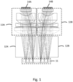
- Fig. 1 shows an example of the multi-pupil projector having two exit pupils 14A, 14B.
- the projector contains a microdisplay 11, such as a liquid crystal on silicon (LCOS) microdisplay, two polarizing beam splitters 12A, 12B, and illumination optics units 13A, 13B.
- LCOS liquid crystal on silicon
- a beam splitter cube which can be used as the polarizing beam splitter has the same height as the display width.
- the volume required by the cubes is significantly reduced.
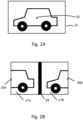
- the optical axis 26 is centered with the center point of the LCOS display. This is illustrated in Fig. 2A .
- a black stripe 28 between the two display segments 27A, 27B as shown in Fig. 2B . This prevents cross-talk between the imaging optics units.
- the optical axes of the imaging optics units 28A, 28B needs to be at side edges of the display, as shown in Fig. 2B . Then the black stripe in the LCOS display contributes to side regions of the final image, where the black stripe is not noticeable for the user.
- the optical axes are moved to corner points of the microdisplay and instead of a black stripe, a black cross is used to isolate the four display segments. This kind of lateral shifting of the image at the panel in one or two dimensions therefore allows for utilizing a single microdisplay panel without undesired side-effects in the resulting image quality.
- One advantage of a multi-pupil projector is that the projector unit can utilize both polarization states of the incident illumination.
- LEDs light emitting diodes
- TE transverse electric
- TM transverse magnetic
- one or more polarization-sensitive elements are used to increase the efficiency of the projector.
- polarizing beam splitter cubes using different wire grid orientations or a polarization state conversion plate that rotates the polarization by 90 degrees can be employed between the light source and the display panel of the display element.
- These embodiments are best suitable for LCOS type displays.
- the projector contains two polarizing beam splitter cubes 32A, 32B whose wire grids 33A, 33B have a 90 deg orientation difference in respect of each other.
- the direction of wires in the wire grids is denoted by W .
- the projector contains two identical polarizing beam splitter cubes 42A, 42B.
- the TE part 45 reflects towards the LCOS display 41.
- the TM part 46 continues towards a ⁇ 2 waveplate 47 that turns the TM polarized light 46 into TE polarized 48.
- the light rays reflect from the wire grid polarizer 43B towards the LCOS display 41.
- polarizing beam splitter cubes instead of polarizing beam splitter cubes, also polarizing beam splitter plates can be used in the constructions of Fig. 3 and 4 .
- Figs. 5A and 5B illustrate two lightguides 51, 55, respectively, that could be used with a dual pupil projector when stacked on top of each other.
- the lightguides 51, 55 contain in-coupling gratings 52, 56, exit pupil expansion gratings 53, 57, and out-coupling gratings 54, 58.
- the distance between the in-couplers 52, 56 in the x-direction is so small that the projector can be implemented with a single display.
- the in-coupler 52 of the first lightguide that is closer to the projector is illuminated directly without any obstacles between the projector and the in-coupler 52, while the in-coupler 56 of the second lightguide will be illuminated through the exit pupil expansion grating 53 of the first lightguide 51. Because of this, the exit pupil expander 53 may couple some light into the first lightguide 51 but this light will not be ever out-coupled by the out-coupling grating 54 and thus it will not be visible for the user. It only reduces the amount of light energy coupled into the second lightguide 55.
- the in-coupling gratings 52, 56 are located adjacent to each other, typically located laterally central along the width (or height, depending on the confguration) of the lightguide means. Their distance can be e.g. less than 50% of the width of the out-coupling grating, for example e.g. 15 mm or less, such as 10 mm or less. "Laterally central” herein means within the centermost third of the element, when divided into three sections of equal width by two parallel lines.
- Figs. 6A and 6B illustrate a variation where in-couplers 62, 66 of lightguides 61, 65, respectively, are very far away from each other in the x-direction.
- the lightguides also contain exit pupil expansion gratings 63, 67 and out-coupling gratings 64, 68.
- in-coupling gratings 62, 66 are locate relatively far from each other, it is preferred to use this embodiment in combination with a projector that utilizes separate microdisplays for the respective image segments.
- "Far from each other" herein means that the in-coupling gratings are laterally separated by a distance, which is more than 50 %, in particular more than 100 %, of a corresponding dimension the out-coupling grating. In practice, this distance can be e.g. 15 - 50 mm, whereby the gratings may be located in the vicinity of opposite corners of the lightguide means.
- the distance between the in-coupling gratings 62, 66 can be e.g. more than 50 % of the width of the out-coupling grating, such as more than 15 mm, such as 20 mm or more.
- the distance can be more than the width of the out-coupling grating, as is the case in the example of Figs. 6A/6B .
- the exit pupil expansion gratings 53, 56 / 63, 67 extend to opposite directions form the in-coupling gratings such that they overlap with each other and the out-coupling gratings 54, 58 / 64, 68 are placed in relation to the in-coupling gratings 52, 56 / 62, 66 and the exit pupil expansion gratings 53, 57 / 63, 67 so that the diffracted light waves hit them and they together form the full FOV based on the partial FOVs targeted to the in-coupling gratings 54, 58 / 64, 68.
- the in-couplers 72, 76 of lightguides 71, 75 are located in the same corner region (herein the top left corner) of the lightguides but displaced from each other, but do not laterally overlap with the exit pupil expander gratings 73, 77.
- This configuration is particularly preferred in cases where the projector needs to be located for example in a temple of smart eyewear.
- "Corner region” herein means one quarter of the element, when divided with two perpendicular lines.
- the out-coupling gratings do not produce any strong, disturbing rainbow patters due to ambient light, contrary to what may happen when grating lines are horizontal.
- the exit pupil expanders 73, 77 can have various shapes depending how the ray paths leading from the in-coupler to the out-coupler have been designed.
- Corner placement of in-couplers can be implemented also in the case of horizontal out-coupler grating lines like in Figs. 5A, 5B / 6A, 6B .
- the lightguide layers which the gratings are manufactured on are preferably optically transparent. They may be made of glass or polymer. Transparent herein means transmittance higher than 50 %, in particular higher than 95 %.
- the gratings in each layer can be manufactured on the same side or different sides thereof. There may also be one or more intermediate layers or coatings in the stack, which have influence on the optical or mechanical properties thereof.
- the period of the gratings herein discussed is typically 10 ⁇ m or less, in particular 1 ⁇ m or less, such as 200 - 800 nm.
- One or more projectors and one or more lightguide elements of the above kind can be arranged into a suitable frame, in particular a wearable frame, so as to provide a functional personal display.
- a suitable frame in particular a wearable frame
- the present technology is, however, not usable only in NEDs and HMDs, but also in HUDs, for example.
- the number of pupils can be larger than that, such as three, four or even more.
Landscapes
- Physics & Mathematics (AREA)
- General Physics & Mathematics (AREA)
- Optics & Photonics (AREA)
- Diffracting Gratings Or Hologram Optical Elements (AREA)
Claims (18)
- Élément guide de lumière multi-pupilles pour un dispositif d'affichage personnel diffractif, comprenant- des moyens de guidage de lumière (51, 55, 61, 65),- des moyens de couplage d'entrée diffractifs (52, 56, 62, 66) pour coupler une image dirigée vers les moyens de couplage d'entrée (52, 56, 62, 66) dans les moyens de guidage de lumière,- des moyens de couplage de sortie diffractifs (54, 58, 64, 68) pour coupler ladite image en sortie des moyens de guidage de lumière,dans lequel- les moyens de couplage d'entrée diffractifs (52, 56, 62, 66) comprennent au moins deux réseaux de couplage d'entrée décalés latéralement l'un par rapport à l'autre sur lesdits moyens de guidage de lumière (51, 55, 61, 65) pour recevoir des segments d'image, qui portent un champ de vision partiel de ladite image, et- les moyens de couplage de sortie diffractifs (54, 58, 64, 68) sont associés optiquement auxdits au moins deux réseaux de couplage d'entrée pour reproduire ladite image à partir desdits segments d'image,- un réseau d'expansion de pupille de sortie (53, 57, 63, 67) pour chaque réseau de couplage d'entrée, les réseaux d'expansion de pupille de sortie (53, 57, 63, 67) étant associés à et agencés optiquement entre au moins un desdits réseaux de couplage d'entrée et lesdits moyens de couplage de sortie (54, 58, 64, 68), pour élargir la pupille de sortie de l'élément,caractérisé en ce quelesdits réseaux de couplage d'entrée et réseaux d'expansion de pupille de sortie (53, 57, 63, 67) sont situés de sorte qu'un premier réseau de couplage d'entrée associé à un premier réseau d'expansion de pupille de sortie chevauche latéralement un second réseau d'expansion de pupille de sortie associé à un second réseau de couplage d'entrée,lesdits réseaux de couplage d'entrée sont décalés latéralement par rapport auxdits réseaux d'expansion de pupille de sortie (53, 57, 63, 67), etl'élément comprend une première paire de réseau de couplage d'entrée et de réseau d'expansion de pupille de sortie associé et une seconde paire de réseau de couplage d'entrée et de réseau d'expansion de pupille de sortie associé, qui est sensiblement positionnée de manière symétrique en miroir sur les moyens de guidage de lumière (51, 55, 61, 65) par rapport à la première paire.
- Élément selon la revendication 1, dans lequel les moyens de couplage de sortie diffractifs (54, 58, 64, 68) comprennent au moins deux réseaux de couplage de sortie se chevauchant latéralement sur lesdits moyens de guidage de lumière (51, 55, 61, 65), les au moins deux réseaux de couplage de sortie étant optiquement associés auxdits au moins deux réseaux de couplage d'entrée, respectivement, pour reproduire ladite image à partir desdits segments d'image.
- Élément selon la revendication 1 ou 2, dans lequel les moyens de guidage de lumière (54, 58, 64, 68) comprennent au moins deux guides de lumière empilés l'un sur l'autre, lesdits réseaux de couplage d'entrée et lesdits moyens de couplage de sortie (54, 58, 64, 68) étant agencés sur lesdits au moins deux guides d'ondes, respectivement.
- Élément selon l'une quelconque des revendications 1-3, dans lequel les réseaux d'expansion de pupille de sortie (53, 57, 63, 67) associés à différents réseaux de couplage d'entrée et réseaux de couplage de sortie se chevauchent, c'est-à-dire sont alignés latéralement les uns avec les autres ; ou sont complètement alignés, c'est-à-dire présentent la même forme et sont positionnés au même endroit.
- Élément selon l'une quelconque des revendications précédentes, dans lequel lesdits au moins deux réseaux de couplage d'entrée sont séparés latéralement par une distance qui correspond à- 50 % ou moins d'une dimension correspondante du réseau de couplage de sortie, telle que 0-15 mm, et située latéralement au centre le long de ladite dimension ou dans la zone de coin des moyens de guidage de lumière (51, 55, 61, 65), ou- plus de 50% d'une dimension correspondante du réseau de couplage de sortie, telle que 15-50 mm, et à proximité de coins opposés des moyens de guidage de lumière (51, 55, 61, 65) le long de ladite dimension.
- Dispositif d'affichage personnel, en particulier un affichage proche de l'œil, dans lequel le dispositif comprend- un élément guide de lumière multi-pupilles selon l'une quelconque des revendications précédentes pour produire une image visible à l'œil nu sur les moyens de couplage de sortie (54, 58, 64, 68) de celui-ci, et- un projecteur multi-pupilles apte à projeter au moins deux segments d'image différents de ladite image sur lesdits au moins deux réseaux de couplage d'entrée.
- Dispositif selon la revendication 6, dans lequel le projecteur comprend un panneau d'affichage dont les différentes zones sont utilisées pour produire lesdits différents segments d'image.
- Dispositif selon l'une quelconque des revendications 6-7, dans lequel ledit projecteur est conçu pour produire l'image sur ledit panneau d'affichage de sorte que lesdits segments d'image soient en configuration décalée latéralement dans au moins une dimension latérale du panneau d'affichage, les segments étant facultativement séparés par une zone de séparation noire pour empêcher l'interférence entre les segments dans ledit projecteur ou sur ledit élément guide de lumière multi-pupilles.
- Dispositif selon l'une quelconque des revendications 6-8, dans lequel le projecteur comprend une pluralité de panneaux d'affichage qui sont utilisés pour produire lesdits différents segments d'image.
- Dispositif selon l'une quelconque des revendications 6-9, dans lequel les réseaux de couplage de sortie comprennent des lignes de réseau orientées en direction horizontale ou en direction verticale.
- Dispositif selon l'une quelconque des revendications 6-10, dans lequel le projecteur comprend au moins un élément d'affichage pour afficher une image et au moins deux pupilles de sortie, dans lequel ledit élément d'affichage comprend une source de lumière non polarisée et des moyens pour utiliser deux états de polarisation différents de ladite source de lumière pour projeter lesdits segments d'image sur lesdites pupilles de sortie.
- Dispositif selon l'une quelconque des revendications 11, dans lequel l'élément d'affichage comprend un panneau d'affichage à cristaux liquides sur silicium (LCOS) ou analogue et un système d'éclairage comprenant au moins deux séparateurs de faisceau polarisants agencés en séquence pour utiliser deux états de polarisation différents de lumière pour projeter lesdits au moins deux segments d'image différents.
- Dispositif selon l'une quelconque des revendications 11-12, dans lequel le projecteur comprend des moyens optiques pour projeter au moins deux segments différents de ladite image vers lesdites au moins deux pupilles de sortie, respectivement, dans lequel lesdits moyens optiques comprennent deux séparateurs de faisceau successifs, tels que des cubes ou plaques de séparation de faisceau, présentant des orientations de polarisation perpendiculaires.
- Dispositif selon l'une quelconque des revendications 11-12, dans lequel le projecteur comprend des moyens optiques pour projeter au moins deux segments différents de ladite image vers lesdites au moins deux pupilles de sortie, respectivement, dans lequel lesdits moyens optiques comprennent deux séparateurs de faisceau successifs, tels que des cubes ou plaques de séparation de faisceau, présentant la même orientation de polarisation et une lame-onde de demi-longueur d'onde agencée optiquement entre les séparateurs de faisceau.
- Procédé d'affichage d'une image sur un dispositif d'affichage personnel, le procédé comprenant- la projection d'au moins deux segments d'image de champ de vision partiel différents d'une image totale sur au moins deux réseaux de couplage d'entrée diffractifs décalés latéralement l'un par rapport à l'autre sur des moyens de guidage de lumière (51, 55, 61, 65), les réseaux de couplage d'entrée couplant lesdits segments d'image aux moyens de guidage de lumière (51, 55, 61, 65),- le guidage des segments d'image vers au moins un réseau de couplage de sortie diffractif pour reproduire ladite image totale à partir desdits segments d'image,dans lequel les segments d'image sont guidés vers ledit au moins un réseau de couplage de sortie par l'intermédiaire de réseaux d'expansion de pupille de sortie (53, 57, 63, 67), les réseaux d'expansion de pupille de sortie (53, 57, 63, 67) étant associés à et agencés optiquement entre au moins un desdits réseaux de couplage d'entrée et ledit au moins un réseau de couplage de sortie pour élargir la pupille de sortie de l'élément,caractérisé en ce quelesdits réseaux de couplage d'entrée et réseaux d'expansion de pupille de sortie (53, 57, 63, 67) sont situés de sorte qu'un premier réseau de couplage d'entrée associé à un premier réseau d'expansion de pupille de sortie chevauche latéralement un second réseau d'expansion de pupille de sortie associé à un second réseau de couplage d'entrée,lesdits réseaux de couplage d'entrée sont décalés latéralement par rapport auxdits réseaux d'expansion de pupille de sortie (53, 57, 63, 67), etl'élément comprend une première paire de réseau de couplage d'entrée et de réseau d'expansion de pupille de sortie associé et une seconde paire de réseau de couplage d'entrée et de réseau d'expansion de pupille de sortie associé, qui est sensiblement positionnée de manière symétrique en miroir sur les moyens de guidage de lumière (51, 55, 61, 65) par rapport à la première paire.
- Procédé selon la revendication 15, dans lequel les segments d'image sont guidés vers au moins deux réseaux de couplage de sortie se chevauchant latéralement sur lesdits moyens de guidage de lumière (51, 55, 61, 65) pour reproduire ladite image totale à partir desdits segments d'image.
- Procédé selon l'une quelconque des revendications 15-16, dans lequel les différents segments d'image sont guidés sur différentes couches de guidage de lumière empilées les unes sur les autres et comprenant chacune un réseau de couplage d'entrée et un réseau de couplage de sortie optiquement associé au réseau de couplage d'entrée, et un réseau d'expansion de pupille de sortie (53, 57, 63, 67) agencé optiquement entre le réseau de couplage d'entrée (52, 56) et le réseau de couplage de sortie associé.
- Procédé selon l'une quelconque des revendications 14-17, dans lequel l'élément d'affichage selon l'une quelconque des revendications 1-5 ou le dispositif d'affichage personnel selon l'une quelconque des revendications 6-14 est utilisé.
Applications Claiming Priority (2)
| Application Number | Priority Date | Filing Date | Title |
|---|---|---|---|
| FI20175413A FI129873B (en) | 2017-05-08 | 2017-05-08 | Diffractive display, light guide element and projector, and method of displaying image |
| PCT/FI2018/050341 WO2018206848A1 (fr) | 2017-05-08 | 2018-05-08 | Affichage diffractif, élément de guidage de lumière et son projecteur, et procédé d'affichage d'image |
Publications (4)
| Publication Number | Publication Date |
|---|---|
| EP3622334A1 EP3622334A1 (fr) | 2020-03-18 |
| EP3622334A4 EP3622334A4 (fr) | 2020-12-30 |
| EP3622334C0 EP3622334C0 (fr) | 2025-01-22 |
| EP3622334B1 true EP3622334B1 (fr) | 2025-01-22 |
Family
ID=64104454
Family Applications (1)
| Application Number | Title | Priority Date | Filing Date |
|---|---|---|---|
| EP18798173.3A Active EP3622334B1 (fr) | 2017-05-08 | 2018-05-08 | Affichage diffractif, élément de guidage de lumière et son projecteur, et procédé d'affichage d'image |
Country Status (6)
| Country | Link |
|---|---|
| US (1) | US11391943B2 (fr) |
| EP (1) | EP3622334B1 (fr) |
| JP (1) | JP7195496B2 (fr) |
| CN (1) | CN110603467B (fr) |
| FI (1) | FI129873B (fr) |
| WO (1) | WO2018206848A1 (fr) |
Families Citing this family (16)
| Publication number | Priority date | Publication date | Assignee | Title |
|---|---|---|---|---|
| US10551544B2 (en) | 2018-01-21 | 2020-02-04 | Lumus Ltd. | Light-guide optical element with multiple-axis internal aperture expansion |
| FI128573B (en) * | 2018-03-28 | 2020-08-14 | Dispelix Oy | Waveguide display element |
| IL309806B2 (en) | 2018-09-09 | 2025-11-01 | Lumus Ltd | Optical systems including light-guide optical elements with two-dimensional expansion |
| CA3123518C (fr) * | 2019-01-24 | 2023-07-04 | Lumus Ltd. | Systemes optiques comprenant un loe a expansion a trois etages |
| CN117784310A (zh) | 2020-05-24 | 2024-03-29 | 鲁姆斯有限公司 | 制造复合光导光学元件的方法、光学结构 |
| EP4172678B1 (fr) | 2020-06-25 | 2026-02-25 | Magic Leap, Inc. | Oculaire pour visiocasque et procédé pour la fabrication de celui-ci |
| DE202021104723U1 (de) | 2020-09-11 | 2021-10-18 | Lumus Ltd. | An ein optisches Lichtleiterelement gekoppelter Bildprojektor |
| WO2022070197A1 (fr) | 2020-10-01 | 2022-04-07 | Lumus Ltd. | Éléments optiques de guidage de lumière composés |
| WO2022086002A1 (fr) | 2020-10-20 | 2022-04-28 | Samsung Electronics Co., Ltd. | Structure de guide d'ondes à éléments optiques diffractifs segmentés et appareil d'affichage proche de l'œil l'utilisant |
| EP4279980A4 (fr) * | 2021-02-09 | 2024-07-31 | Guangdong Oppo Mobile Telecommunications Corp., Ltd. | Appareil d'affichage à réalité augmentée et dispositif d'affichage proche de l'oeil |
| AU2022226493B2 (en) | 2021-02-25 | 2023-07-27 | Lumus Ltd. | Optical aperture multipliers having a rectangular waveguide |
| CN113219671B (zh) * | 2021-05-25 | 2025-12-19 | 深圳市光舟半导体技术有限公司 | 光学装置和显示设备 |
| JP2023050616A (ja) * | 2021-09-30 | 2023-04-11 | セイコーエプソン株式会社 | 虚像表示装置 |
| US20230359031A1 (en) * | 2022-05-09 | 2023-11-09 | Visera Technologies Company Limited | Waveguide structure and display device using the same |
| US20240004199A1 (en) * | 2022-07-01 | 2024-01-04 | Google Llc | Partially curved lightguide with pupil replicators |
| US20240418992A1 (en) * | 2023-06-14 | 2024-12-19 | Applied Materials, Inc. | Large-field-of-view single-sheet waveguide combiners |
Citations (1)
| Publication number | Priority date | Publication date | Assignee | Title |
|---|---|---|---|---|
| EP3423877B1 (fr) * | 2016-02-29 | 2022-10-26 | Magic Leap, Inc. | Systèmes et procédés de réalité virtuelle et augmentée |
Family Cites Families (19)
| Publication number | Priority date | Publication date | Assignee | Title |
|---|---|---|---|---|
| FI20030583A7 (fi) * | 2003-04-16 | 2004-10-17 | Upstream Eng Oy | Dataprojektori |
| EP1639394A2 (fr) | 2003-06-10 | 2006-03-29 | Elop Electro-Optics Industries Ltd. | Procede et systeme servant a afficher une image informative sur une image d'arriere-plan |
| WO2008081070A1 (fr) * | 2006-12-28 | 2008-07-10 | Nokia Corporation | Dispositif pour étendre une pupille de sortie en deux dimensions |
| US8508848B2 (en) * | 2007-12-18 | 2013-08-13 | Nokia Corporation | Exit pupil expanders with wide field-of-view |
| US7613373B1 (en) | 2008-07-03 | 2009-11-03 | Microvision, Inc. | Substrate guided relay with homogenizing input relay |
| ES2717200T3 (es) | 2008-12-12 | 2019-06-19 | Bae Systems Plc | Mejoras en las guías de ondas o relacionadas con estas |
| JP5133925B2 (ja) | 2009-03-25 | 2013-01-30 | オリンパス株式会社 | 頭部装着型画像表示装置 |
| WO2011107831A1 (fr) * | 2010-03-04 | 2011-09-09 | Nokia Corporation | Appareil optique et procédé pour dilater une pupille de sortie |
| DE102010030138A1 (de) | 2010-06-15 | 2011-12-15 | Fraunhofer-Gesellschaft zur Förderung der angewandten Forschung e.V. | Projektionsdisplay und Verfahren zum Anzeigen eines Gesamtbilds |
| GB201114149D0 (en) | 2011-08-17 | 2011-10-05 | Bae Systems Plc | Projection display |
| US8989535B2 (en) * | 2012-06-04 | 2015-03-24 | Microsoft Technology Licensing, Llc | Multiple waveguide imaging structure |
| US9019615B2 (en) | 2012-06-12 | 2015-04-28 | Microsoft Technology Licensing, Llc | Wide field-of-view virtual image projector |
| WO2014091200A1 (fr) | 2012-12-10 | 2014-06-19 | Bae Systems Plc | Dispositif d'affichage comprenant un guide d'ondes optiques et des réseaux de diffraction commutables et son procédé de fabrication |
| US9244281B1 (en) * | 2013-09-26 | 2016-01-26 | Rockwell Collins, Inc. | Display system and method using a detached combiner |
| US11402629B2 (en) * | 2013-11-27 | 2022-08-02 | Magic Leap, Inc. | Separated pupil optical systems for virtual and augmented reality and methods for displaying images using same |
| US9827209B2 (en) * | 2015-02-09 | 2017-11-28 | Microsoft Technology Licensing, Llc | Display system |
| JP2017022942A (ja) | 2015-07-14 | 2017-01-26 | キヤノン株式会社 | 振動型アクチュエータの制御装置とその制御方法、駆動装置、撮像装置、及び自動ステージ |
| US10007117B2 (en) | 2015-09-10 | 2018-06-26 | Vuzix Corporation | Imaging light guide with reflective turning array |
| US9885870B2 (en) | 2016-04-25 | 2018-02-06 | Microsoft Technology Licensing, Llc | Diffractive optical elements with analog modulations and switching |
-
2017
- 2017-05-08 FI FI20175413A patent/FI129873B/en active IP Right Grant
-
2018
- 2018-05-08 WO PCT/FI2018/050341 patent/WO2018206848A1/fr not_active Ceased
- 2018-05-08 US US16/610,925 patent/US11391943B2/en active Active
- 2018-05-08 EP EP18798173.3A patent/EP3622334B1/fr active Active
- 2018-05-08 JP JP2019561956A patent/JP7195496B2/ja active Active
- 2018-05-08 CN CN201880030178.7A patent/CN110603467B/zh active Active
Patent Citations (1)
| Publication number | Priority date | Publication date | Assignee | Title |
|---|---|---|---|---|
| EP3423877B1 (fr) * | 2016-02-29 | 2022-10-26 | Magic Leap, Inc. | Systèmes et procédés de réalité virtuelle et augmentée |
Also Published As
| Publication number | Publication date |
|---|---|
| FI129873B (en) | 2022-10-14 |
| JP7195496B2 (ja) | 2022-12-26 |
| FI20175413A1 (fi) | 2018-11-09 |
| JP2020519955A (ja) | 2020-07-02 |
| US20200081246A1 (en) | 2020-03-12 |
| WO2018206848A1 (fr) | 2018-11-15 |
| EP3622334C0 (fr) | 2025-01-22 |
| CN110603467A (zh) | 2019-12-20 |
| US11391943B2 (en) | 2022-07-19 |
| EP3622334A1 (fr) | 2020-03-18 |
| CN110603467B (zh) | 2022-04-05 |
| EP3622334A4 (fr) | 2020-12-30 |
Similar Documents
| Publication | Publication Date | Title |
|---|---|---|
| EP3622334B1 (fr) | Affichage diffractif, élément de guidage de lumière et son projecteur, et procédé d'affichage d'image | |
| JP7656100B2 (ja) | 入力開口が小さく、かつ高効率なコンパクトヘッドマウントディスプレイシステム | |
| KR102805976B1 (ko) | 스캐닝 반사기를 갖는 대형 시야 디스플레이를 위한 방법 및 시스템 | |
| US8913324B2 (en) | Display illumination light guide | |
| JP2022160457A (ja) | ウェアラブルディスプレイのための照明装置 | |
| US20210109347A1 (en) | Waveguide element and waveguide stack for display applications | |
| EP2124087B1 (fr) | Lentille à imagerie guidée par substrat avec un premier et un second substrat | |
| US11307429B2 (en) | Single RGB combiner with large field of view | |
| CN115390347A (zh) | 包括伪影抑制的投影仪架构 | |
| US11002906B2 (en) | Waveguide device and optical engine | |
| US12585094B2 (en) | Anamorphic directional illumination device | |
| CN119856098A (zh) | 变形定向照明装置 | |
| US20250224550A1 (en) | Multiple wavelength range imaging light guide system | |
| US12449670B2 (en) | Optical elements for displays | |
| US20250053011A1 (en) | Multi-input image light guide system | |
| US12619086B2 (en) | Near-eye display systems utilizing an array of projectors | |
| US12601868B2 (en) | Optical waveguide arrangement with improved capacity | |
| US20240427152A1 (en) | Anamorphic directional illumination device | |
| US20240427161A1 (en) | Anamorphic directional illumination device | |
| US20240085714A1 (en) | Near-eye display systems utilizing an array of projectors | |
| JP2025532075A (ja) | デュアルプロジェクタシステム及び画像光ガイド | |
| CN117849932A (zh) | 一种增强现实显示组件及设备 |
Legal Events
| Date | Code | Title | Description |
|---|---|---|---|
| STAA | Information on the status of an ep patent application or granted ep patent |
Free format text: STATUS: THE INTERNATIONAL PUBLICATION HAS BEEN MADE |
|
| PUAI | Public reference made under article 153(3) epc to a published international application that has entered the european phase |
Free format text: ORIGINAL CODE: 0009012 |
|
| STAA | Information on the status of an ep patent application or granted ep patent |
Free format text: STATUS: REQUEST FOR EXAMINATION WAS MADE |
|
| 17P | Request for examination filed |
Effective date: 20191108 |
|
| AK | Designated contracting states |
Kind code of ref document: A1 Designated state(s): AL AT BE BG CH CY CZ DE DK EE ES FI FR GB GR HR HU IE IS IT LI LT LU LV MC MK MT NL NO PL PT RO RS SE SI SK SM TR |
|
| AX | Request for extension of the european patent |
Extension state: BA ME |
|
| DAV | Request for validation of the european patent (deleted) | ||
| DAX | Request for extension of the european patent (deleted) | ||
| A4 | Supplementary search report drawn up and despatched |
Effective date: 20201202 |
|
| RIC1 | Information provided on ipc code assigned before grant |
Ipc: G02B 27/42 20060101ALI20201126BHEP Ipc: G02B 27/00 20060101ALI20201126BHEP Ipc: G02B 27/01 20060101ALI20201126BHEP Ipc: G02B 5/18 20060101AFI20201126BHEP |
|
| STAA | Information on the status of an ep patent application or granted ep patent |
Free format text: STATUS: EXAMINATION IS IN PROGRESS |
|
| 17Q | First examination report despatched |
Effective date: 20230217 |
|
| RAP3 | Party data changed (applicant data changed or rights of an application transferred) |
Owner name: DISPELIX OY |
|
| GRAP | Despatch of communication of intention to grant a patent |
Free format text: ORIGINAL CODE: EPIDOSNIGR1 |
|
| STAA | Information on the status of an ep patent application or granted ep patent |
Free format text: STATUS: GRANT OF PATENT IS INTENDED |
|
| INTG | Intention to grant announced |
Effective date: 20240920 |
|
| GRAS | Grant fee paid |
Free format text: ORIGINAL CODE: EPIDOSNIGR3 |
|
| GRAA | (expected) grant |
Free format text: ORIGINAL CODE: 0009210 |
|
| STAA | Information on the status of an ep patent application or granted ep patent |
Free format text: STATUS: THE PATENT HAS BEEN GRANTED |
|
| AK | Designated contracting states |
Kind code of ref document: B1 Designated state(s): AL AT BE BG CH CY CZ DE DK EE ES FI FR GB GR HR HU IE IS IT LI LT LU LV MC MK MT NL NO PL PT RO RS SE SI SK SM TR |
|
| REG | Reference to a national code |
Ref country code: GB Ref legal event code: FG4D |
|
| REG | Reference to a national code |
Ref country code: CH Ref legal event code: EP |
|
| REG | Reference to a national code |
Ref country code: IE Ref legal event code: FG4D |
|
| REG | Reference to a national code |
Ref country code: DE Ref legal event code: R096 Ref document number: 602018078701 Country of ref document: DE |
|
| U01 | Request for unitary effect filed |
Effective date: 20250218 |
|
| U07 | Unitary effect registered |
Designated state(s): AT BE BG DE DK EE FI FR IT LT LU LV MT NL PT RO SE SI Effective date: 20250224 |
|
| U20 | Renewal fee for the european patent with unitary effect paid |
Year of fee payment: 8 Effective date: 20250527 |
|
| PG25 | Lapsed in a contracting state [announced via postgrant information from national office to epo] |
Ref country code: RS Free format text: LAPSE BECAUSE OF FAILURE TO SUBMIT A TRANSLATION OF THE DESCRIPTION OR TO PAY THE FEE WITHIN THE PRESCRIBED TIME-LIMIT Effective date: 20250422 |
|
| PG25 | Lapsed in a contracting state [announced via postgrant information from national office to epo] |
Ref country code: PL Free format text: LAPSE BECAUSE OF FAILURE TO SUBMIT A TRANSLATION OF THE DESCRIPTION OR TO PAY THE FEE WITHIN THE PRESCRIBED TIME-LIMIT Effective date: 20250122 |
|
| PG25 | Lapsed in a contracting state [announced via postgrant information from national office to epo] |
Ref country code: ES Free format text: LAPSE BECAUSE OF FAILURE TO SUBMIT A TRANSLATION OF THE DESCRIPTION OR TO PAY THE FEE WITHIN THE PRESCRIBED TIME-LIMIT Effective date: 20250122 |
|
| PGFP | Annual fee paid to national office [announced via postgrant information from national office to epo] |
Ref country code: GB Payment date: 20250527 Year of fee payment: 8 |
|
| PG25 | Lapsed in a contracting state [announced via postgrant information from national office to epo] |
Ref country code: IS Free format text: LAPSE BECAUSE OF FAILURE TO SUBMIT A TRANSLATION OF THE DESCRIPTION OR TO PAY THE FEE WITHIN THE PRESCRIBED TIME-LIMIT Effective date: 20250522 Ref country code: NO Free format text: LAPSE BECAUSE OF FAILURE TO SUBMIT A TRANSLATION OF THE DESCRIPTION OR TO PAY THE FEE WITHIN THE PRESCRIBED TIME-LIMIT Effective date: 20250422 |
|
| PG25 | Lapsed in a contracting state [announced via postgrant information from national office to epo] |
Ref country code: HR Free format text: LAPSE BECAUSE OF FAILURE TO SUBMIT A TRANSLATION OF THE DESCRIPTION OR TO PAY THE FEE WITHIN THE PRESCRIBED TIME-LIMIT Effective date: 20250122 |
|
| PG25 | Lapsed in a contracting state [announced via postgrant information from national office to epo] |
Ref country code: GR Free format text: LAPSE BECAUSE OF FAILURE TO SUBMIT A TRANSLATION OF THE DESCRIPTION OR TO PAY THE FEE WITHIN THE PRESCRIBED TIME-LIMIT Effective date: 20250423 |
|
| PG25 | Lapsed in a contracting state [announced via postgrant information from national office to epo] |
Ref country code: SM Free format text: LAPSE BECAUSE OF FAILURE TO SUBMIT A TRANSLATION OF THE DESCRIPTION OR TO PAY THE FEE WITHIN THE PRESCRIBED TIME-LIMIT Effective date: 20250122 |
|
| PG25 | Lapsed in a contracting state [announced via postgrant information from national office to epo] |
Ref country code: CZ Free format text: LAPSE BECAUSE OF FAILURE TO SUBMIT A TRANSLATION OF THE DESCRIPTION OR TO PAY THE FEE WITHIN THE PRESCRIBED TIME-LIMIT Effective date: 20250122 |
|
| PG25 | Lapsed in a contracting state [announced via postgrant information from national office to epo] |
Ref country code: SK Free format text: LAPSE BECAUSE OF FAILURE TO SUBMIT A TRANSLATION OF THE DESCRIPTION OR TO PAY THE FEE WITHIN THE PRESCRIBED TIME-LIMIT Effective date: 20250122 |
|
| PLBE | No opposition filed within time limit |
Free format text: ORIGINAL CODE: 0009261 |
|
| STAA | Information on the status of an ep patent application or granted ep patent |
Free format text: STATUS: NO OPPOSITION FILED WITHIN TIME LIMIT |
|
| REG | Reference to a national code |
Ref country code: CH Ref legal event code: L10 Free format text: ST27 STATUS EVENT CODE: U-0-0-L10-L00 (AS PROVIDED BY THE NATIONAL OFFICE) Effective date: 20251203 |
|
| REG | Reference to a national code |
Ref country code: CH Ref legal event code: H13 Free format text: ST27 STATUS EVENT CODE: U-0-0-H10-H13 (AS PROVIDED BY THE NATIONAL OFFICE) Effective date: 20251223 |
|
| 26N | No opposition filed |
Effective date: 20251023 |
|
| PG25 | Lapsed in a contracting state [announced via postgrant information from national office to epo] |
Ref country code: CH Free format text: LAPSE BECAUSE OF NON-PAYMENT OF DUE FEES Effective date: 20250531 |
|
| PG25 | Lapsed in a contracting state [announced via postgrant information from national office to epo] |
Ref country code: MC Free format text: LAPSE BECAUSE OF FAILURE TO SUBMIT A TRANSLATION OF THE DESCRIPTION OR TO PAY THE FEE WITHIN THE PRESCRIBED TIME-LIMIT Effective date: 20250122 |
|
| PG25 | Lapsed in a contracting state [announced via postgrant information from national office to epo] |
Ref country code: IE Free format text: LAPSE BECAUSE OF NON-PAYMENT OF DUE FEES Effective date: 20250508 |