EP3622854A1 - Meuble constitue d'une structure formée d'un cadre tubulaire assemblé par connecteurs - Google Patents
Meuble constitue d'une structure formée d'un cadre tubulaire assemblé par connecteurs Download PDFInfo
- Publication number
- EP3622854A1 EP3622854A1 EP19185227.6A EP19185227A EP3622854A1 EP 3622854 A1 EP3622854 A1 EP 3622854A1 EP 19185227 A EP19185227 A EP 19185227A EP 3622854 A1 EP3622854 A1 EP 3622854A1
- Authority
- EP
- European Patent Office
- Prior art keywords
- furniture
- frame
- profile
- tubular
- corner connector
- Prior art date
- Legal status (The legal status is an assumption and is not a legal conclusion. Google has not performed a legal analysis and makes no representation as to the accuracy of the status listed.)
- Withdrawn
Links
Images


Classifications
-
- F—MECHANICAL ENGINEERING; LIGHTING; HEATING; WEAPONS; BLASTING
- F16—ENGINEERING ELEMENTS AND UNITS; GENERAL MEASURES FOR PRODUCING AND MAINTAINING EFFECTIVE FUNCTIONING OF MACHINES OR INSTALLATIONS; THERMAL INSULATION IN GENERAL
- F16B—DEVICES FOR FASTENING OR SECURING CONSTRUCTIONAL ELEMENTS OR MACHINE PARTS TOGETHER, e.g. NAILS, BOLTS, CIRCLIPS, CLAMPS, CLIPS OR WEDGES; JOINTS OR JOINTING
- F16B12/00—Jointing of furniture or the like, e.g. hidden from exterior
- F16B12/44—Leg joints; Corner joints
-
- A—HUMAN NECESSITIES
- A47—FURNITURE; DOMESTIC ARTICLES OR APPLIANCES; COFFEE MILLS; SPICE MILLS; SUCTION CLEANERS IN GENERAL
- A47B—TABLES; DESKS; OFFICE FURNITURE; CABINETS; DRAWERS; GENERAL DETAILS OF FURNITURE
- A47B47/00—Cabinets, racks or shelf units, characterised by features related to dismountability or building-up from elements
- A47B47/0016—Node corner connectors, e.g. cubic
-
- A—HUMAN NECESSITIES
- A47—FURNITURE; DOMESTIC ARTICLES OR APPLIANCES; COFFEE MILLS; SPICE MILLS; SUCTION CLEANERS IN GENERAL
- A47B—TABLES; DESKS; OFFICE FURNITURE; CABINETS; DRAWERS; GENERAL DETAILS OF FURNITURE
- A47B47/00—Cabinets, racks or shelf units, characterised by features related to dismountability or building-up from elements
- A47B47/0025—Horizontal connecting members adapted to receive and retain the edges of several panel elements
- A47B47/0033—Corners
-
- A—HUMAN NECESSITIES
- A47—FURNITURE; DOMESTIC ARTICLES OR APPLIANCES; COFFEE MILLS; SPICE MILLS; SUCTION CLEANERS IN GENERAL
- A47F—SPECIAL FURNITURE, FITTINGS, OR ACCESSORIES FOR SHOPS, STOREHOUSES, BARS, RESTAURANTS OR THE LIKE; PAYING COUNTERS
- A47F5/00—Show stands, hangers, or shelves characterised by their constructional features
- A47F5/10—Adjustable or foldable or dismountable display stands
- A47F5/13—Adjustable or foldable or dismountable display stands made of tubes or wire
- A47F5/135—Adjustable or foldable or dismountable display stands made of tubes or wire adapted for regular transport to a display area
- A47F5/137—Adjustable or foldable or dismountable display stands made of tubes or wire adapted for regular transport to a display area having wheels
-
- F—MECHANICAL ENGINEERING; LIGHTING; HEATING; WEAPONS; BLASTING
- F16—ENGINEERING ELEMENTS AND UNITS; GENERAL MEASURES FOR PRODUCING AND MAINTAINING EFFECTIVE FUNCTIONING OF MACHINES OR INSTALLATIONS; THERMAL INSULATION IN GENERAL
- F16B—DEVICES FOR FASTENING OR SECURING CONSTRUCTIONAL ELEMENTS OR MACHINE PARTS TOGETHER, e.g. NAILS, BOLTS, CIRCLIPS, CLAMPS, CLIPS OR WEDGES; JOINTS OR JOINTING
- F16B12/00—Jointing of furniture or the like, e.g. hidden from exterior
- F16B12/40—Joints for furniture tubing
- F16B12/42—Joints for furniture tubing connecting furniture tubing to non-tubular parts
-
- A—HUMAN NECESSITIES
- A47—FURNITURE; DOMESTIC ARTICLES OR APPLIANCES; COFFEE MILLS; SPICE MILLS; SUCTION CLEANERS IN GENERAL
- A47B—TABLES; DESKS; OFFICE FURNITURE; CABINETS; DRAWERS; GENERAL DETAILS OF FURNITURE
- A47B31/00—Service or tea tables, trolleys, or wagons
- A47B2031/004—Service or tea tables, trolleys, or wagons having four vertical uprights
-
- A—HUMAN NECESSITIES
- A47—FURNITURE; DOMESTIC ARTICLES OR APPLIANCES; COFFEE MILLS; SPICE MILLS; SUCTION CLEANERS IN GENERAL
- A47B—TABLES; DESKS; OFFICE FURNITURE; CABINETS; DRAWERS; GENERAL DETAILS OF FURNITURE
- A47B2230/00—Furniture jointing; Furniture with such jointing
- A47B2230/14—Furniture connections by means of two half-shells
-
- F—MECHANICAL ENGINEERING; LIGHTING; HEATING; WEAPONS; BLASTING
- F16—ENGINEERING ELEMENTS AND UNITS; GENERAL MEASURES FOR PRODUCING AND MAINTAINING EFFECTIVE FUNCTIONING OF MACHINES OR INSTALLATIONS; THERMAL INSULATION IN GENERAL
- F16B—DEVICES FOR FASTENING OR SECURING CONSTRUCTIONAL ELEMENTS OR MACHINE PARTS TOGETHER, e.g. NAILS, BOLTS, CIRCLIPS, CLAMPS, CLIPS OR WEDGES; JOINTS OR JOINTING
- F16B12/00—Jointing of furniture or the like, e.g. hidden from exterior
- F16B12/40—Joints for furniture tubing
- F16B2012/406—Cove joints for joining two cylindrical members
-
- F—MECHANICAL ENGINEERING; LIGHTING; HEATING; WEAPONS; BLASTING
- F16—ENGINEERING ELEMENTS AND UNITS; GENERAL MEASURES FOR PRODUCING AND MAINTAINING EFFECTIVE FUNCTIONING OF MACHINES OR INSTALLATIONS; THERMAL INSULATION IN GENERAL
- F16B—DEVICES FOR FASTENING OR SECURING CONSTRUCTIONAL ELEMENTS OR MACHINE PARTS TOGETHER, e.g. NAILS, BOLTS, CIRCLIPS, CLAMPS, CLIPS OR WEDGES; JOINTS OR JOINTING
- F16B7/00—Connections of rods or tubes, e.g. of non-circular section, mutually, including resilient connections
- F16B7/04—Clamping or clipping connections
Definitions
- the invention relates to a piece of furniture with a frame made of tubular or profile frames connected via at least one corner connector.
- Tubular furniture often has corner connectors at its corners, via which the ends of individual tubular struts are connected to one another.
- corner connectors for example in the corner region.
- Such arrangements are for example from the DE 20 2011 110 083 U1 and from the DE 3930614 A1 known.
- the tubular furniture known from the prior art has the disadvantage that the required stability of the construction cannot generally be ensured by the corner connectors alone, since the corner connectors should also not be made too massive for aesthetic reasons. It is common to give the tubular furniture, in particular its cuboid tubular frame, additional stability by means of cross struts or side wall elements. However, this in turn limits the freedom of design of such tubular furniture.
- a piece of furniture of the type described in the introduction which has a frame made of a plurality of tubular or profile frames, of which at least two tubular or profile frames are connected to one another in a corner region of the frame by means of a multi-part corner connector, the corner connector being a first and a second Has part that are releasably connected to each other and between which the at least two tubular or profile frames are held, and wherein one of the first and second parts on a side facing away from the frame has a mechanical interface for attaching an attachment.
- the furniture according to the invention has increased stability compared to furniture known from the prior art.
- the add-on part can be a plate lying in the corner region on the frame, which is connected via the interface to the corner connector, for which purpose the corner connector has a third part which is attached to the plate, preferably latched and via the interface to the at least one of the first and the second part is releasably set.
- the interface can, for example, have or be an assembly level on which the attachment can be attached.
- the interface can have, for example, a thread receptacle or a different suitable fastening means depending on the type of attachment.
- the add-on part can have, for example, a third part of the corner connector, which can be fixed via the interface on the first and / or the second part of the corner connector.
- the attachment can have, for example, a furniture base, a transport roller, a plate or a holder for an object, for example for a folded sheet metal plate.
- the tubular or profile frames can be all-round closed tubular or profile frames.
- the tube or profile frame can, for example, be flat tube or profile frame, that is to say tube or profile frame, which only extend in two spatial dimensions and whose dimension in the third spatial direction is determined solely by a diameter of the tube forming the tube or profile frame or the strut forming the tube or profile frame or the profile forming the tube or profile frame is predetermined.
- the tube or profile frame can, for example, have a rectangular geometry, with two pairs of tube or profile sections each extending parallel to one another, two tube sections bordering one another in a corner region of the tube or profile frame being perpendicular to one another.
- the pipe sections adjoining each other in the corner region of the tubular or profile frame can also run at a larger or smaller angle between approximately 10 ° and 170 ° to one another.
- the struts forming the tube or profile frame can be, for example, tubes, solid rods, wires or profiles and in principle do not have to be limited to specific embodiments.
- the pipe or profile frame In the corner area in which the pipe or profile sections merge, the pipe or profile frame can be rounded.
- the tubular or profile frame in the corner area can have a radius that is greater than 1 cm.
- the first and the second part can have a channel between each tube or profile frame held, in which the respective tube or profile frame is received in a form-fitting manner.
- the first and the second part can each have a recess on opposite sides, which delimit the channel in the case of assembled parts.
- the channel can have a non-linear profile, preferably a round profile with a constant radius at least in sections. Due to the non-linear course of the channel, the corner connector is firmly locked in relation to the respective tubular or profile frame that is inserted into the channel and in particular cannot be displaced in the direction of extension of the tubular or profile frame.
- the channel can be opened on its opposite ends in the direction of extension on two different sides of the corner connector.
- the two sides of the corner connector, to which the channel is open, can be aligned perpendicular to one another, for example.
- Such a corner connector is particularly suitable by creating a cubic piece of furniture.
- the two sides can also be arranged at any other angle of preferably between 10 ° and 170 ° to one another in order to create a non-cubic piece of furniture.
- the two channels can each have a first opening which is open on the same side of the corner connector, the channels each having a second opening which are each open on one of two further sides, the three sides preferably being arranged perpendicular to one another.
- a corner connector is particularly suitable for creating a cubic piece of furniture, that is to say for creating a frame with a cubic geometry.
- the three sides can also be arranged in pairs at any other angle of preferably between 10 ° and 170 ° to one another in order to create a non-cubic piece of furniture.
- the at least two tube or profile frames connected to one another via the corner connector can each be a flat rectangular frame, the respective rectangular frame having a rounded tube profile in its corner region
- the third part which is fastened to the plate, can have a first mounting level, via which the third part is detachably fixed to the at least one of the first and second parts.
- the third part can have a further assembly level, which is set back from the first assembly level and on which the plate rests on its outer circumference with a flange of an edge encompassing the third part. It can thereby be achieved that the flange is aligned with the first assembly side or is set back with respect to the first assembly side, thereby enabling the assembly of a further component on the first assembly side.
- the further component can be, for example, a sheet metal part, for example a baying connector or a side wall element.
- the third part can have a fastening means, preferably a locking means, on its further mounting level, which can be pivoted relative to the further mounting level between a release position and a locking position.
- the latching means can in particular be a latching lug which is arranged in a recess in the further assembly plane and can be pivoted with respect to the further assembly plane, in particular between a position in which a form-fitting piece is retracted into the third part at a free end of the latching lug, and one Locking position in which the locking lug with the form-fitting piece protrudes from the third part over the further assembly level. In this way, the form-fitting piece can be received in a corresponding latching receptacle of the flange in the latching position.
- the plate can, for example, be a sheet metal part which is only produced by edging and punching.
- the plate can have a U-fold on one of its edges, of which a free profile section at the end of the U-fold forms the flange, which can rest on the further assembly plane and can be fixed thereon.
- the flange can, for example, have a recess, preferably a through hole, with which the fastening means, preferably the latching means, is engaged when the plate is in an assembly position with respect to the third part.
- the recess or the through bore can have a geometry that corresponds to the geometry of a form-fitting piece of the fastening means, in particular the latching means, so that the fastening means or the latching means can be received in a form-fitting manner in the recess around the plate with respect to the third part to lock in the mounting position.
- the plate can encompass the third part with a flange of a fold on its outer circumference, a gap being formed between the third part and one of the first and second parts, into which a sheet metal part, for example a side wall element of the piece of furniture, is inserted.
- the gap can be formed between a projection on the outer circumference of that part of the first and second part which has the interface and the further assembly plane, for which purpose the further assembly plane projects vertically beyond the outer circumference.
- the sheet metal part in particular the side wall element, can engage with an L-fold along a horizontal lower edge in the gap.
- the third part can have on its first mounting level a further fastening means, preferably a further locking means, which can be pivoted relative to the first mounting level between a release position and a locking position.
- the latching means can be designed as a latching lug which can be pivoted with respect to the assembly plane and which has at its free end a form-fitting adapter for receiving in a corresponding recess in the L-fold.
- the L-fold can have a recess, preferably a through hole or an opening, with which the further fastening means, preferably the latching means, is engaged when the L-fold is in an assembly position with respect to the corner connector.
- the first and the second part can be connected to one another via at least one first screw connection.
- the first and the second part can have aligned through bores, via which the first and the second part are screwed to the third part via a further screw connection.
- the structure of the piece of furniture according to the invention also enables simple assembly of the piece of furniture. Accordingly, in a first step, two tubular or profile frames can be fixed to one another via the first and the second part of the corner connector.
- the two parts can each have partial receptacles on their opposite and adjoining sides, in which, in the assembled state of the two parts, the tubular or profile frames in the corner region are received in a form-fitting or essentially form-fitting manner and, due to their non-linear course in the corner region, are locked to one another in the case of parts which are firmly connected to one another are.
- the third part can be fixed to the plate using the fastening means, in particular a snap-in connection.
- the plate can in particular have a U-fold on its circumference and in the corner area, the third part engaging with a free flange of the U-fold.
- the plate can be, for example, a sheet metal part, which is only produced by edging and punching is.
- the U-fold can be interrupted, in particular in the corner area of the plate, in order to prevent the plate from being deformed in the corner area in terms of production technology.
- the third part can have a decorative piece which, when the third part is inserted into the U-fold, closes the interruption of the U-fold in an aesthetically pleasing manner.
- the third part and the already connected first and second parts can then be connected to one another.
- the first and the second part can have aligned passages in their connected assembly position, via which a screw bolt or the like can be screwed through the first and the second part into the third part, for which purpose the third part can have an internal thread.
- the kinematic reversal should also be encompassed by the invention, according to which the internal thread is formed in at least one of the first and second part and the through hole in the third part.
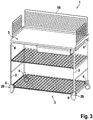
- the furniture 1 is characterized by its frame 2, which has essentially rectangular outer dimensions.
- the frame 2 is composed of four flat tubular frames 3, each of which is aligned vertically, tubular frames 3 adjoining one another in a corner region being fixed to one another perpendicularly by a corner connector 4.
- a corresponding frame 2 is in Figure 4 shown.
- the top of the frame 2 is covered by a plate 5, which is also connected to the frame 2 via the corner connector 4 in the corner regions of the frame 2.
- the bottom-side corner connectors 4 have fastening receptacles at an interface 29, for example in order to fix transport rollers, furniture feet or the like.
- the interface 29 can have an assembly level with fastening receptacles, for example threaded receptacles.
- All corner connectors 4 can be designed as identical parts.
- the in the Figures 2 and 3rd The embodiments shown differ in particular from that in FIG Figure 1 shown embodiment that they have a side wall element 16, which is also fixed to the furniture via the four upper corner connectors 4. Details of this are explained with reference to the following figures.
- the corner connector 4 has a first part 6, a second part 7 and a third part 8.
- the third part 8 is fixed, in particular screwed, via its assembly level M1 at the interface 29 of the second part 7.
- a first pair of screws 26 are provided to fix the first part to the second part and a second pair of screws 27 are provided to fix the already connected first and second parts 6, 7 to the third part 8.
- the second part 6, 7 can have blind holes for a nut 28, via which the first and second parts 6, 7 can be connected to one another with the aid of the first pair of screws 26.
- the first and second parts 6, 7 each have a channel 9 on their mutually facing sides, in which the two tubular frames 3 arranged at right angles to one another can be received, so that the two tubular frames 3 when the first and second parts 6, 7 are screwed together are firmly fixed to one another in the alignment prescribed by the form fit.
- the fact that the tubular frame 3 is enclosed by the corner connector 4 in a corner area ensures that the corner connector 4 is immovably locked to the tubular frame 3 despite the round geometry of the tubular frame 3. If the first and the second part 6, 7 are fixed to one another, they form the channel 9 between them, in which the respective tubular frame 3 is received in a form-fitting manner.
- the corner connector 4 has exactly two channels 9, each having a first opening 10, the openings 10 being open on the same side of the corner connector 4.
- the channels 9 also each have a second opening 10, each of which is open on one of two further sides.
- the three sides of the corner connector 4 are perpendicular to each other. Compare too Figures 7 and 8th .
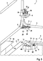
- the Figures 5 and 6 further illustrate the assembly of the third part 8 in the corner region of a U-shaped edge 12 of the plate 5.
- the edge 12 encompasses the third part 8 with a flange 11 of the edge 12.
- the third part 8 has on its further mounting level M2 a fastening means 13 which is designed as a locking means and can be pivoted relative to the further mounting level M2 between a release position and a locking position.
- the locking means 13 is designed as a locking lug, which has a form-fitting piece at its free end, which engages in a form-fitting manner in a recess 14 in the flange 11 when the third part 8 is inserted into the U-fold 12 and thus the third part 8 in the mounting position in Corner area of the plate 5 locked.
- the third part 8 also has a first mounting plate M1, with which the third part can be releasably secured to the at least one of the first and second parts 6, 7 via the interface 29.
- the further assembly level M2 is set back from the first assembly level M1.
- the plate 5 lies with a flange 11 of a U-fold 12 encompassing the third part 8, so that the flange 11 is aligned with the first assembly plane M1 or is set back with respect to the first assembly plane M1. It is thus achieved that the mounting of the plate 5 via the U-fold 12, in particular the flange 11, does not hinder the mounting of a further flat component, something of a side wall element on the first mounting level M1.
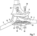
- the Figure 7 shows a detailed view in the corner area of a piece of furniture according to the invention, wherein only the first and the second part 6, 7 of the corner connector 4 as well as the tubular frame 3 inserted into the corner connector and aligned perpendicular to each other can still be seen. If according to the illustration Figure 7 upper part 6, 7 is lowered onto the lower part 6, 7, the two tubular frames 3 are positively received between the two parts 6, 7. By screwing the two parts to one another with first screw bolts 26, the two tubular frames 3 can be locked in the given orientation relative to one another.
- the two frames 3 can be screwed to the third part 8.
- the assembled partial corner connector consisting of the first and second parts 6, 7 has through holes aligned and the third part has corresponding internal threads 22, via which two screw bolts 27 are used to produce a screw connection between the three parts 6, 7, 8 and thereby the plate 5 can be set to the tubular frame 3.
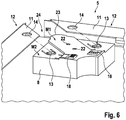
- a side wall element 16 can be attached to the furniture.
- a gap 15 is formed between the third part 8 and one of the first and second parts 6, 7, in which the side wall element 16 of the furniture 1 is inserted.
- the gap 15 can be formed between a projection 25 on the outer circumference of that part of the first and second part 6, 7, which is arranged between the first and the third part 8, and the further assembly plane M2, for which purpose the further assembly plane M2 is perpendicular to the outer circumference protrudes.
- the illustrated embodiment engages the side wall element 16 with an L-fold 17, which is formed along a horizontal lower edge of the side wall element 16, in the gap 15.
- the third part 8 has a further fastening means 18 on its first assembly level M1, which is designed as a further latching means.
- the locking means can be pivoted relative to the first assembly level M1 between a release position and a locking position.
- the further fastening means can be designed analogously to the first fastening means for locking the plate 5.
- the L-fold 17 has a recess 19, which is designed as a through hole or a rectangular opening, via which the further fastening means 18 is engaged when the L-fold 17 is in the assembly position with respect to the corner connector 4.
- the mounting position is in Figure 10 shown.
Landscapes
- Engineering & Computer Science (AREA)
- General Engineering & Computer Science (AREA)
- Mechanical Engineering (AREA)
- Assembled Shelves (AREA)
- Furniture Connections (AREA)
Applications Claiming Priority (1)
| Application Number | Priority Date | Filing Date | Title |
|---|---|---|---|
| DE202018105258.6U DE202018105258U1 (de) | 2018-09-13 | 2018-09-13 | Möbel mit einem Rahmengestell aus über einen Eckverbinder verbundenen Rohrrahmen |
Publications (1)
| Publication Number | Publication Date |
|---|---|
| EP3622854A1 true EP3622854A1 (fr) | 2020-03-18 |
Family
ID=63797331
Family Applications (1)
| Application Number | Title | Priority Date | Filing Date |
|---|---|---|---|
| EP19185227.6A Withdrawn EP3622854A1 (fr) | 2018-09-13 | 2019-07-09 | Meuble constitue d'une structure formée d'un cadre tubulaire assemblé par connecteurs |
Country Status (2)
| Country | Link |
|---|---|
| EP (1) | EP3622854A1 (fr) |
| DE (1) | DE202018105258U1 (fr) |
Citations (3)
| Publication number | Priority date | Publication date | Assignee | Title |
|---|---|---|---|---|
| EP0964107A1 (fr) * | 1998-06-09 | 1999-12-15 | Husson Collectivites, S.A. | Noeud d'assemblage |
| DE202010000222U1 (de) * | 2010-02-18 | 2010-04-15 | Patech Gmbh | Klemmelement |
| US20120294675A1 (en) * | 2011-05-18 | 2012-11-22 | Wen-Tsung Chang | Assembled structure with connectors |
Family Cites Families (2)
| Publication number | Priority date | Publication date | Assignee | Title |
|---|---|---|---|---|
| DE3930614A1 (de) | 1988-09-13 | 1990-03-29 | Linder Gmbh A | Moebeleckverbinder |
| DE202011110083U1 (de) | 2011-05-07 | 2013-01-07 | Josef Stengel | Rohrverbinder |
-
2018
- 2018-09-13 DE DE202018105258.6U patent/DE202018105258U1/de not_active Expired - Lifetime
-
2019
- 2019-07-09 EP EP19185227.6A patent/EP3622854A1/fr not_active Withdrawn
Patent Citations (3)
| Publication number | Priority date | Publication date | Assignee | Title |
|---|---|---|---|---|
| EP0964107A1 (fr) * | 1998-06-09 | 1999-12-15 | Husson Collectivites, S.A. | Noeud d'assemblage |
| DE202010000222U1 (de) * | 2010-02-18 | 2010-04-15 | Patech Gmbh | Klemmelement |
| US20120294675A1 (en) * | 2011-05-18 | 2012-11-22 | Wen-Tsung Chang | Assembled structure with connectors |
Also Published As
| Publication number | Publication date |
|---|---|
| DE202018105258U1 (de) | 2018-09-20 |
Similar Documents
| Publication | Publication Date | Title |
|---|---|---|
| EP3384567B1 (fr) | Châssis pour armoire électrique | |
| EP1259738B1 (fr) | Dispositif de connexion de profiles | |
| EP3572605A1 (fr) | Ensemble charnière pour un boîtier d'armoire de distribution et boîtier d'armoire de distribution correspondant | |
| EP0136431A2 (fr) | Ossature en profilés | |
| DE202014103897U1 (de) | Rohrverbinder | |
| EP3529430B1 (fr) | Montant pour une construction à montant et traverse | |
| DE102011056463B4 (de) | Gehäuse zum Aufnehmen von Bauteilen, insbesondere von elektronischen Baugruppen, Bauelementen und dergleichen | |
| EP4095331A1 (fr) | Dispositif d'accouplement pour la construction modulaire de bâtiments ou d'objets | |
| EP3529868B1 (fr) | Ensemble connecteur pour la connexion de deux châssis d'armoires électriques | |
| DE102013006723A1 (de) | Hohlprofilträger für eine Tragvorrichtung zum Tragen von Werkzeugen, Werkstücken oder dergleichen, System zum Aufbauen einer derartigen Tragvorrichtung sowie Kreuzverbinder und Vorrichtung zur Befestigung eines Endeffektors an einem Grundrahmen an einer derartigen Tragvorrichtung | |
| DE202015104250U1 (de) | Pfosten-Riegel-Verbindung | |
| EP3607624B1 (fr) | Ensemble comprenant un socle et un châssis pour armoire électrique ainsi qu'une rangée d'armoires électriques | |
| EP3659222B1 (fr) | Agencement avec deux châssis d'armoire connectés par un dispositif d'assemblage | |
| EP3636844A1 (fr) | Cadre de construction sèche pour une porte coulissante | |
| DE102013103947A1 (de) | Verbindung zwischen Profilelementen einer Rahmenkonstruktion | |
| WO2010006459A1 (fr) | Unité siège et banc | |
| DE102016015791B4 (de) | Verbindungsanordnung für die Verbindung von zwei Schaltschrankrahmengestellen | |
| DE102021115852B4 (de) | Montageanordnung für den Innenausbau eines Schaltschrankgehäuses | |
| EP4114150A1 (fr) | Ensemble d'extension | |
| EP3622854A1 (fr) | Meuble constitue d'une structure formée d'un cadre tubulaire assemblé par connecteurs | |
| DE3442231A1 (de) | Raumkonstruktion | |
| EP1798186A1 (fr) | Cabine d'ascenseur et méthode de montage de panneaux d'une parroi de cabine | |
| DE29712998U1 (de) | Eckverbinder | |
| EP4424210B1 (fr) | Tiroir d'étagère | |
| EP3130716B1 (fr) | Panneau de mur et systeme de panneaux de mur pour la construction de stand d'exposition |
Legal Events
| Date | Code | Title | Description |
|---|---|---|---|
| PUAI | Public reference made under article 153(3) epc to a published international application that has entered the european phase |
Free format text: ORIGINAL CODE: 0009012 |
|
| STAA | Information on the status of an ep patent application or granted ep patent |
Free format text: STATUS: THE APPLICATION HAS BEEN PUBLISHED |
|
| AK | Designated contracting states |
Kind code of ref document: A1 Designated state(s): AL AT BE BG CH CY CZ DE DK EE ES FI FR GB GR HR HU IE IS IT LI LT LU LV MC MK MT NL NO PL PT RO RS SE SI SK SM TR |
|
| AX | Request for extension of the european patent |
Extension state: BA ME |
|
| STAA | Information on the status of an ep patent application or granted ep patent |
Free format text: STATUS: REQUEST FOR EXAMINATION WAS MADE |
|
| 17P | Request for examination filed |
Effective date: 20200818 |
|
| RBV | Designated contracting states (corrected) |
Designated state(s): AL AT BE BG CH CY CZ DE DK EE ES FI FR GB GR HR HU IE IS IT LI LT LU LV MC MK MT NL NO PL PT RO RS SE SI SK SM TR |
|
| STAA | Information on the status of an ep patent application or granted ep patent |
Free format text: STATUS: EXAMINATION IS IN PROGRESS |
|
| 17Q | First examination report despatched |
Effective date: 20201006 |
|
| STAA | Information on the status of an ep patent application or granted ep patent |
Free format text: STATUS: THE APPLICATION IS DEEMED TO BE WITHDRAWN |
|
| 18D | Application deemed to be withdrawn |
Effective date: 20221220 |