EP3622936B1 - Gehhilfevorrichtung - Google Patents
Gehhilfevorrichtung Download PDFInfo
- Publication number
- EP3622936B1 EP3622936B1 EP19195846.1A EP19195846A EP3622936B1 EP 3622936 B1 EP3622936 B1 EP 3622936B1 EP 19195846 A EP19195846 A EP 19195846A EP 3622936 B1 EP3622936 B1 EP 3622936B1
- Authority
- EP
- European Patent Office
- Prior art keywords
- walking
- unit
- state
- user
- assist device
- Prior art date
- Legal status (The legal status is an assumption and is not a legal conclusion. Google has not performed a legal analysis and makes no representation as to the accuracy of the status listed.)
- Not-in-force
Links
- 238000001514 detection method Methods 0.000 claims description 180
- 238000011156 evaluation Methods 0.000 claims description 167
- 238000012549 training Methods 0.000 claims description 88
- 238000012937 correction Methods 0.000 claims description 73
- 230000009471 action Effects 0.000 claims description 31
- 230000006870 function Effects 0.000 claims description 27
- 238000000605 extraction Methods 0.000 claims description 11
- 238000004364 calculation method Methods 0.000 claims description 9
- 239000000284 extract Substances 0.000 claims description 8
- 238000000034 method Methods 0.000 description 130
- 230000008569 process Effects 0.000 description 96
- 230000007704 transition Effects 0.000 description 37
- 239000013256 coordination polymer Substances 0.000 description 33
- 230000036760 body temperature Effects 0.000 description 18
- 230000001133 acceleration Effects 0.000 description 15
- 230000008859 change Effects 0.000 description 9
- 230000005856 abnormality Effects 0.000 description 8
- 230000010354 integration Effects 0.000 description 6
- 238000012935 Averaging Methods 0.000 description 4
- 230000003247 decreasing effect Effects 0.000 description 4
- 230000007246 mechanism Effects 0.000 description 4
- 101100386724 Schizosaccharomyces pombe (strain 972 / ATCC 24843) nhm1 gene Proteins 0.000 description 3
- 230000008602 contraction Effects 0.000 description 3
- 238000010586 diagram Methods 0.000 description 3
- 230000009467 reduction Effects 0.000 description 3
- 238000009795 derivation Methods 0.000 description 2
- 238000005259 measurement Methods 0.000 description 2
- 230000005855 radiation Effects 0.000 description 2
- 230000002159 abnormal effect Effects 0.000 description 1
- 230000017531 blood circulation Effects 0.000 description 1
- 230000007423 decrease Effects 0.000 description 1
- 230000000694 effects Effects 0.000 description 1
- 230000007935 neutral effect Effects 0.000 description 1
- 230000002787 reinforcement Effects 0.000 description 1
- 230000004044 response Effects 0.000 description 1
Images

















Classifications
-
- A—HUMAN NECESSITIES
- A61—MEDICAL OR VETERINARY SCIENCE; HYGIENE
- A61H—PHYSICAL THERAPY APPARATUS, e.g. DEVICES FOR LOCATING OR STIMULATING REFLEX POINTS IN THE BODY; ARTIFICIAL RESPIRATION; MASSAGE; BATHING DEVICES FOR SPECIAL THERAPEUTIC OR HYGIENIC PURPOSES OR SPECIFIC PARTS OF THE BODY
- A61H1/00—Apparatus for passive exercising; Vibrating apparatus; Chiropractic devices, e.g. body impacting devices, external devices for briefly extending or aligning unbroken bones
- A61H1/02—Stretching or bending or torsioning apparatus for exercising
- A61H1/0274—Stretching or bending or torsioning apparatus for exercising for the upper limbs
- A61H1/0277—Elbow
-
- A—HUMAN NECESSITIES
- A61—MEDICAL OR VETERINARY SCIENCE; HYGIENE
- A61H—PHYSICAL THERAPY APPARATUS, e.g. DEVICES FOR LOCATING OR STIMULATING REFLEX POINTS IN THE BODY; ARTIFICIAL RESPIRATION; MASSAGE; BATHING DEVICES FOR SPECIAL THERAPEUTIC OR HYGIENIC PURPOSES OR SPECIFIC PARTS OF THE BODY
- A61H3/00—Appliances for aiding patients or disabled persons to walk about
- A61H3/04—Wheeled walking aids for patients or disabled persons
-
- A—HUMAN NECESSITIES
- A61—MEDICAL OR VETERINARY SCIENCE; HYGIENE
- A61B—DIAGNOSIS; SURGERY; IDENTIFICATION
- A61B5/00—Measuring for diagnostic purposes; Identification of persons
- A61B5/02—Detecting, measuring or recording for evaluating the cardiovascular system, e.g. pulse, heart rate, blood pressure or blood flow
- A61B5/0205—Simultaneously evaluating both cardiovascular conditions and different types of body conditions, e.g. heart and respiratory condition
- A61B5/02055—Simultaneously evaluating both cardiovascular condition and temperature
-
- A—HUMAN NECESSITIES
- A61—MEDICAL OR VETERINARY SCIENCE; HYGIENE
- A61B—DIAGNOSIS; SURGERY; IDENTIFICATION
- A61B5/00—Measuring for diagnostic purposes; Identification of persons
- A61B5/02—Detecting, measuring or recording for evaluating the cardiovascular system, e.g. pulse, heart rate, blood pressure or blood flow
- A61B5/024—Measuring pulse rate or heart rate
- A61B5/02416—Measuring pulse rate or heart rate using photoplethysmograph signals, e.g. generated by infrared radiation
- A61B5/02427—Details of sensor
- A61B5/02433—Details of sensor for infrared radiation
-
- A—HUMAN NECESSITIES
- A61—MEDICAL OR VETERINARY SCIENCE; HYGIENE
- A61B—DIAGNOSIS; SURGERY; IDENTIFICATION
- A61B5/00—Measuring for diagnostic purposes; Identification of persons
- A61B5/103—Measuring devices for testing the shape, pattern, colour, size or movement of the body or parts thereof, for diagnostic purposes
- A61B5/11—Measuring movement of the entire body or parts thereof, e.g. head or hand tremor or mobility of a limb
- A61B5/1118—Determining activity level
-
- A—HUMAN NECESSITIES
- A61—MEDICAL OR VETERINARY SCIENCE; HYGIENE
- A61B—DIAGNOSIS; SURGERY; IDENTIFICATION
- A61B5/00—Measuring for diagnostic purposes; Identification of persons
- A61B5/103—Measuring devices for testing the shape, pattern, colour, size or movement of the body or parts thereof, for diagnostic purposes
- A61B5/11—Measuring movement of the entire body or parts thereof, e.g. head or hand tremor or mobility of a limb
- A61B5/112—Gait analysis
-
- A—HUMAN NECESSITIES
- A61—MEDICAL OR VETERINARY SCIENCE; HYGIENE
- A61B—DIAGNOSIS; SURGERY; IDENTIFICATION
- A61B5/00—Measuring for diagnostic purposes; Identification of persons
- A61B5/68—Arrangements of detecting, measuring or recording means, e.g. sensors, in relation to patient
- A61B5/6887—Arrangements of detecting, measuring or recording means, e.g. sensors, in relation to patient mounted on external non-worn devices, e.g. non-medical devices
-
- A—HUMAN NECESSITIES
- A61—MEDICAL OR VETERINARY SCIENCE; HYGIENE
- A61H—PHYSICAL THERAPY APPARATUS, e.g. DEVICES FOR LOCATING OR STIMULATING REFLEX POINTS IN THE BODY; ARTIFICIAL RESPIRATION; MASSAGE; BATHING DEVICES FOR SPECIAL THERAPEUTIC OR HYGIENIC PURPOSES OR SPECIFIC PARTS OF THE BODY
- A61H1/00—Apparatus for passive exercising; Vibrating apparatus; Chiropractic devices, e.g. body impacting devices, external devices for briefly extending or aligning unbroken bones
- A61H1/02—Stretching or bending or torsioning apparatus for exercising
- A61H1/0274—Stretching or bending or torsioning apparatus for exercising for the upper limbs
- A61H1/0281—Shoulder
-
- A—HUMAN NECESSITIES
- A63—SPORTS; GAMES; AMUSEMENTS
- A63B—APPARATUS FOR PHYSICAL TRAINING, GYMNASTICS, SWIMMING, CLIMBING, OR FENCING; BALL GAMES; TRAINING EQUIPMENT
- A63B21/00—Exercising apparatus for developing or strengthening the muscles or joints of the body by working against a counterforce, with or without measuring devices
- A63B21/02—Exercising apparatus for developing or strengthening the muscles or joints of the body by working against a counterforce, with or without measuring devices using resilient force-resisters
- A63B21/023—Wound springs
-
- A—HUMAN NECESSITIES
- A63—SPORTS; GAMES; AMUSEMENTS
- A63B—APPARATUS FOR PHYSICAL TRAINING, GYMNASTICS, SWIMMING, CLIMBING, OR FENCING; BALL GAMES; TRAINING EQUIPMENT
- A63B21/00—Exercising apparatus for developing or strengthening the muscles or joints of the body by working against a counterforce, with or without measuring devices
- A63B21/02—Exercising apparatus for developing or strengthening the muscles or joints of the body by working against a counterforce, with or without measuring devices using resilient force-resisters
- A63B21/04—Exercising apparatus for developing or strengthening the muscles or joints of the body by working against a counterforce, with or without measuring devices using resilient force-resisters attached to static foundation, e.g. a user
- A63B21/0407—Anchored at two end points, e.g. installed within an apparatus
- A63B21/0414—Anchored at two end points, e.g. installed within an apparatus with both ends stationary during the actual exercise, i.e. moving only at intermediate locations
-
- A—HUMAN NECESSITIES
- A63—SPORTS; GAMES; AMUSEMENTS
- A63B—APPARATUS FOR PHYSICAL TRAINING, GYMNASTICS, SWIMMING, CLIMBING, OR FENCING; BALL GAMES; TRAINING EQUIPMENT
- A63B21/00—Exercising apparatus for developing or strengthening the muscles or joints of the body by working against a counterforce, with or without measuring devices
- A63B21/02—Exercising apparatus for developing or strengthening the muscles or joints of the body by working against a counterforce, with or without measuring devices using resilient force-resisters
- A63B21/05—Linearly-compressed elements
-
- A—HUMAN NECESSITIES
- A63—SPORTS; GAMES; AMUSEMENTS
- A63B—APPARATUS FOR PHYSICAL TRAINING, GYMNASTICS, SWIMMING, CLIMBING, OR FENCING; BALL GAMES; TRAINING EQUIPMENT
- A63B21/00—Exercising apparatus for developing or strengthening the muscles or joints of the body by working against a counterforce, with or without measuring devices
- A63B21/02—Exercising apparatus for developing or strengthening the muscles or joints of the body by working against a counterforce, with or without measuring devices using resilient force-resisters
- A63B21/055—Exercising apparatus for developing or strengthening the muscles or joints of the body by working against a counterforce, with or without measuring devices using resilient force-resisters extension element type
-
- A—HUMAN NECESSITIES
- A63—SPORTS; GAMES; AMUSEMENTS
- A63B—APPARATUS FOR PHYSICAL TRAINING, GYMNASTICS, SWIMMING, CLIMBING, OR FENCING; BALL GAMES; TRAINING EQUIPMENT
- A63B21/00—Exercising apparatus for developing or strengthening the muscles or joints of the body by working against a counterforce, with or without measuring devices
- A63B21/40—Interfaces with the user related to strength training; Details thereof
- A63B21/4041—Interfaces with the user related to strength training; Details thereof characterised by the movements of the interface
- A63B21/4045—Reciprocating movement along, in or on a guide
-
- A—HUMAN NECESSITIES
- A63—SPORTS; GAMES; AMUSEMENTS
- A63B—APPARATUS FOR PHYSICAL TRAINING, GYMNASTICS, SWIMMING, CLIMBING, OR FENCING; BALL GAMES; TRAINING EQUIPMENT
- A63B21/00—Exercising apparatus for developing or strengthening the muscles or joints of the body by working against a counterforce, with or without measuring devices
- A63B21/40—Interfaces with the user related to strength training; Details thereof
- A63B21/4041—Interfaces with the user related to strength training; Details thereof characterised by the movements of the interface
- A63B21/4047—Pivoting movement
-
- A—HUMAN NECESSITIES
- A63—SPORTS; GAMES; AMUSEMENTS
- A63B—APPARATUS FOR PHYSICAL TRAINING, GYMNASTICS, SWIMMING, CLIMBING, OR FENCING; BALL GAMES; TRAINING EQUIPMENT
- A63B23/00—Exercising apparatus specially adapted for particular parts of the body
- A63B23/035—Exercising apparatus specially adapted for particular parts of the body for limbs, i.e. upper or lower limbs, e.g. simultaneously
- A63B23/03516—For both arms together or both legs together; Aspects related to the co-ordination between right and left side limbs of a user
-
- A—HUMAN NECESSITIES
- A63—SPORTS; GAMES; AMUSEMENTS
- A63B—APPARATUS FOR PHYSICAL TRAINING, GYMNASTICS, SWIMMING, CLIMBING, OR FENCING; BALL GAMES; TRAINING EQUIPMENT
- A63B23/00—Exercising apparatus specially adapted for particular parts of the body
- A63B23/035—Exercising apparatus specially adapted for particular parts of the body for limbs, i.e. upper or lower limbs, e.g. simultaneously
- A63B23/03516—For both arms together or both legs together; Aspects related to the co-ordination between right and left side limbs of a user
- A63B23/03533—With separate means driven by each limb, i.e. performing different movements
-
- A—HUMAN NECESSITIES
- A63—SPORTS; GAMES; AMUSEMENTS
- A63B—APPARATUS FOR PHYSICAL TRAINING, GYMNASTICS, SWIMMING, CLIMBING, OR FENCING; BALL GAMES; TRAINING EQUIPMENT
- A63B23/00—Exercising apparatus specially adapted for particular parts of the body
- A63B23/035—Exercising apparatus specially adapted for particular parts of the body for limbs, i.e. upper or lower limbs, e.g. simultaneously
- A63B23/03575—Apparatus used for exercising upper and lower limbs simultaneously
-
- A—HUMAN NECESSITIES
- A63—SPORTS; GAMES; AMUSEMENTS
- A63B—APPARATUS FOR PHYSICAL TRAINING, GYMNASTICS, SWIMMING, CLIMBING, OR FENCING; BALL GAMES; TRAINING EQUIPMENT
- A63B23/00—Exercising apparatus specially adapted for particular parts of the body
- A63B23/035—Exercising apparatus specially adapted for particular parts of the body for limbs, i.e. upper or lower limbs, e.g. simultaneously
- A63B23/04—Exercising apparatus specially adapted for particular parts of the body for limbs, i.e. upper or lower limbs, e.g. simultaneously for lower limbs
-
- A—HUMAN NECESSITIES
- A63—SPORTS; GAMES; AMUSEMENTS
- A63B—APPARATUS FOR PHYSICAL TRAINING, GYMNASTICS, SWIMMING, CLIMBING, OR FENCING; BALL GAMES; TRAINING EQUIPMENT
- A63B23/00—Exercising apparatus specially adapted for particular parts of the body
- A63B23/035—Exercising apparatus specially adapted for particular parts of the body for limbs, i.e. upper or lower limbs, e.g. simultaneously
- A63B23/12—Exercising apparatus specially adapted for particular parts of the body for limbs, i.e. upper or lower limbs, e.g. simultaneously for upper limbs or related muscles, e.g. chest, upper back or shoulder muscles
-
- A—HUMAN NECESSITIES
- A63—SPORTS; GAMES; AMUSEMENTS
- A63B—APPARATUS FOR PHYSICAL TRAINING, GYMNASTICS, SWIMMING, CLIMBING, OR FENCING; BALL GAMES; TRAINING EQUIPMENT
- A63B23/00—Exercising apparatus specially adapted for particular parts of the body
- A63B23/035—Exercising apparatus specially adapted for particular parts of the body for limbs, i.e. upper or lower limbs, e.g. simultaneously
- A63B23/12—Exercising apparatus specially adapted for particular parts of the body for limbs, i.e. upper or lower limbs, e.g. simultaneously for upper limbs or related muscles, e.g. chest, upper back or shoulder muscles
- A63B23/1209—Involving a bending of elbow and shoulder joints simultaneously
-
- A—HUMAN NECESSITIES
- A61—MEDICAL OR VETERINARY SCIENCE; HYGIENE
- A61H—PHYSICAL THERAPY APPARATUS, e.g. DEVICES FOR LOCATING OR STIMULATING REFLEX POINTS IN THE BODY; ARTIFICIAL RESPIRATION; MASSAGE; BATHING DEVICES FOR SPECIAL THERAPEUTIC OR HYGIENIC PURPOSES OR SPECIFIC PARTS OF THE BODY
- A61H3/00—Appliances for aiding patients or disabled persons to walk about
- A61H2003/006—Appliances for aiding patients or disabled persons to walk about with forearm rests, i.e. for non-used arms
-
- A—HUMAN NECESSITIES
- A61—MEDICAL OR VETERINARY SCIENCE; HYGIENE
- A61H—PHYSICAL THERAPY APPARATUS, e.g. DEVICES FOR LOCATING OR STIMULATING REFLEX POINTS IN THE BODY; ARTIFICIAL RESPIRATION; MASSAGE; BATHING DEVICES FOR SPECIAL THERAPEUTIC OR HYGIENIC PURPOSES OR SPECIFIC PARTS OF THE BODY
- A61H3/00—Appliances for aiding patients or disabled persons to walk about
- A61H3/04—Wheeled walking aids for patients or disabled persons
- A61H2003/043—Wheeled walking aids for patients or disabled persons with a drive mechanism
-
- A—HUMAN NECESSITIES
- A61—MEDICAL OR VETERINARY SCIENCE; HYGIENE
- A61H—PHYSICAL THERAPY APPARATUS, e.g. DEVICES FOR LOCATING OR STIMULATING REFLEX POINTS IN THE BODY; ARTIFICIAL RESPIRATION; MASSAGE; BATHING DEVICES FOR SPECIAL THERAPEUTIC OR HYGIENIC PURPOSES OR SPECIFIC PARTS OF THE BODY
- A61H3/00—Appliances for aiding patients or disabled persons to walk about
- A61H3/04—Wheeled walking aids for patients or disabled persons
- A61H2003/046—Wheeled walking aids for patients or disabled persons with braking means
-
- A—HUMAN NECESSITIES
- A61—MEDICAL OR VETERINARY SCIENCE; HYGIENE
- A61H—PHYSICAL THERAPY APPARATUS, e.g. DEVICES FOR LOCATING OR STIMULATING REFLEX POINTS IN THE BODY; ARTIFICIAL RESPIRATION; MASSAGE; BATHING DEVICES FOR SPECIAL THERAPEUTIC OR HYGIENIC PURPOSES OR SPECIFIC PARTS OF THE BODY
- A61H2201/00—Characteristics of apparatus not provided for in the preceding codes
- A61H2201/01—Constructive details
- A61H2201/0173—Means for preventing injuries
-
- A—HUMAN NECESSITIES
- A61—MEDICAL OR VETERINARY SCIENCE; HYGIENE
- A61H—PHYSICAL THERAPY APPARATUS, e.g. DEVICES FOR LOCATING OR STIMULATING REFLEX POINTS IN THE BODY; ARTIFICIAL RESPIRATION; MASSAGE; BATHING DEVICES FOR SPECIAL THERAPEUTIC OR HYGIENIC PURPOSES OR SPECIFIC PARTS OF THE BODY
- A61H2201/00—Characteristics of apparatus not provided for in the preceding codes
- A61H2201/12—Driving means
- A61H2201/1207—Driving means with electric or magnetic drive
- A61H2201/1215—Rotary drive
-
- A—HUMAN NECESSITIES
- A61—MEDICAL OR VETERINARY SCIENCE; HYGIENE
- A61H—PHYSICAL THERAPY APPARATUS, e.g. DEVICES FOR LOCATING OR STIMULATING REFLEX POINTS IN THE BODY; ARTIFICIAL RESPIRATION; MASSAGE; BATHING DEVICES FOR SPECIAL THERAPEUTIC OR HYGIENIC PURPOSES OR SPECIFIC PARTS OF THE BODY
- A61H2201/00—Characteristics of apparatus not provided for in the preceding codes
- A61H2201/12—Driving means
- A61H2201/1253—Driving means driven by a human being, e.g. hand driven
- A61H2201/1261—Driving means driven by a human being, e.g. hand driven combined with active exercising of the patient
-
- A—HUMAN NECESSITIES
- A61—MEDICAL OR VETERINARY SCIENCE; HYGIENE
- A61H—PHYSICAL THERAPY APPARATUS, e.g. DEVICES FOR LOCATING OR STIMULATING REFLEX POINTS IN THE BODY; ARTIFICIAL RESPIRATION; MASSAGE; BATHING DEVICES FOR SPECIAL THERAPEUTIC OR HYGIENIC PURPOSES OR SPECIFIC PARTS OF THE BODY
- A61H2201/00—Characteristics of apparatus not provided for in the preceding codes
- A61H2201/14—Special force transmission means, i.e. between the driving means and the interface with the user
-
- A—HUMAN NECESSITIES
- A61—MEDICAL OR VETERINARY SCIENCE; HYGIENE
- A61H—PHYSICAL THERAPY APPARATUS, e.g. DEVICES FOR LOCATING OR STIMULATING REFLEX POINTS IN THE BODY; ARTIFICIAL RESPIRATION; MASSAGE; BATHING DEVICES FOR SPECIAL THERAPEUTIC OR HYGIENIC PURPOSES OR SPECIFIC PARTS OF THE BODY
- A61H2201/00—Characteristics of apparatus not provided for in the preceding codes
- A61H2201/16—Physical interface with patient
- A61H2201/1602—Physical interface with patient kind of interface, e.g. head rest, knee support or lumbar support
- A61H2201/1635—Hand or arm, e.g. handle
-
- A—HUMAN NECESSITIES
- A61—MEDICAL OR VETERINARY SCIENCE; HYGIENE
- A61H—PHYSICAL THERAPY APPARATUS, e.g. DEVICES FOR LOCATING OR STIMULATING REFLEX POINTS IN THE BODY; ARTIFICIAL RESPIRATION; MASSAGE; BATHING DEVICES FOR SPECIAL THERAPEUTIC OR HYGIENIC PURPOSES OR SPECIFIC PARTS OF THE BODY
- A61H2201/00—Characteristics of apparatus not provided for in the preceding codes
- A61H2201/16—Physical interface with patient
- A61H2201/1602—Physical interface with patient kind of interface, e.g. head rest, knee support or lumbar support
- A61H2201/1635—Hand or arm, e.g. handle
- A61H2201/1638—Holding means therefor
-
- A—HUMAN NECESSITIES
- A61—MEDICAL OR VETERINARY SCIENCE; HYGIENE
- A61H—PHYSICAL THERAPY APPARATUS, e.g. DEVICES FOR LOCATING OR STIMULATING REFLEX POINTS IN THE BODY; ARTIFICIAL RESPIRATION; MASSAGE; BATHING DEVICES FOR SPECIAL THERAPEUTIC OR HYGIENIC PURPOSES OR SPECIFIC PARTS OF THE BODY
- A61H2201/00—Characteristics of apparatus not provided for in the preceding codes
- A61H2201/16—Physical interface with patient
- A61H2201/1657—Movement of interface, i.e. force application means
- A61H2201/1664—Movement of interface, i.e. force application means linear
-
- A—HUMAN NECESSITIES
- A61—MEDICAL OR VETERINARY SCIENCE; HYGIENE
- A61H—PHYSICAL THERAPY APPARATUS, e.g. DEVICES FOR LOCATING OR STIMULATING REFLEX POINTS IN THE BODY; ARTIFICIAL RESPIRATION; MASSAGE; BATHING DEVICES FOR SPECIAL THERAPEUTIC OR HYGIENIC PURPOSES OR SPECIFIC PARTS OF THE BODY
- A61H2201/00—Characteristics of apparatus not provided for in the preceding codes
- A61H2201/16—Physical interface with patient
- A61H2201/1657—Movement of interface, i.e. force application means
- A61H2201/1664—Movement of interface, i.e. force application means linear
- A61H2201/1669—Movement of interface, i.e. force application means linear moving along the body in a reciprocating manner
-
- A—HUMAN NECESSITIES
- A61—MEDICAL OR VETERINARY SCIENCE; HYGIENE
- A61H—PHYSICAL THERAPY APPARATUS, e.g. DEVICES FOR LOCATING OR STIMULATING REFLEX POINTS IN THE BODY; ARTIFICIAL RESPIRATION; MASSAGE; BATHING DEVICES FOR SPECIAL THERAPEUTIC OR HYGIENIC PURPOSES OR SPECIFIC PARTS OF THE BODY
- A61H2201/00—Characteristics of apparatus not provided for in the preceding codes
- A61H2201/16—Physical interface with patient
- A61H2201/1657—Movement of interface, i.e. force application means
- A61H2201/1676—Pivoting
-
- A—HUMAN NECESSITIES
- A61—MEDICAL OR VETERINARY SCIENCE; HYGIENE
- A61H—PHYSICAL THERAPY APPARATUS, e.g. DEVICES FOR LOCATING OR STIMULATING REFLEX POINTS IN THE BODY; ARTIFICIAL RESPIRATION; MASSAGE; BATHING DEVICES FOR SPECIAL THERAPEUTIC OR HYGIENIC PURPOSES OR SPECIFIC PARTS OF THE BODY
- A61H2201/00—Characteristics of apparatus not provided for in the preceding codes
- A61H2201/50—Control means thereof
- A61H2201/5007—Control means thereof computer controlled
-
- A—HUMAN NECESSITIES
- A61—MEDICAL OR VETERINARY SCIENCE; HYGIENE
- A61H—PHYSICAL THERAPY APPARATUS, e.g. DEVICES FOR LOCATING OR STIMULATING REFLEX POINTS IN THE BODY; ARTIFICIAL RESPIRATION; MASSAGE; BATHING DEVICES FOR SPECIAL THERAPEUTIC OR HYGIENIC PURPOSES OR SPECIFIC PARTS OF THE BODY
- A61H2201/00—Characteristics of apparatus not provided for in the preceding codes
- A61H2201/50—Control means thereof
- A61H2201/5007—Control means thereof computer controlled
- A61H2201/501—Control means thereof computer controlled connected to external computer devices or networks
- A61H2201/5012—Control means thereof computer controlled connected to external computer devices or networks using the internet
-
- A—HUMAN NECESSITIES
- A61—MEDICAL OR VETERINARY SCIENCE; HYGIENE
- A61H—PHYSICAL THERAPY APPARATUS, e.g. DEVICES FOR LOCATING OR STIMULATING REFLEX POINTS IN THE BODY; ARTIFICIAL RESPIRATION; MASSAGE; BATHING DEVICES FOR SPECIAL THERAPEUTIC OR HYGIENIC PURPOSES OR SPECIFIC PARTS OF THE BODY
- A61H2201/00—Characteristics of apparatus not provided for in the preceding codes
- A61H2201/50—Control means thereof
- A61H2201/5023—Interfaces to the user
- A61H2201/5043—Displays
-
- A—HUMAN NECESSITIES
- A61—MEDICAL OR VETERINARY SCIENCE; HYGIENE
- A61H—PHYSICAL THERAPY APPARATUS, e.g. DEVICES FOR LOCATING OR STIMULATING REFLEX POINTS IN THE BODY; ARTIFICIAL RESPIRATION; MASSAGE; BATHING DEVICES FOR SPECIAL THERAPEUTIC OR HYGIENIC PURPOSES OR SPECIFIC PARTS OF THE BODY
- A61H2201/00—Characteristics of apparatus not provided for in the preceding codes
- A61H2201/50—Control means thereof
- A61H2201/5023—Interfaces to the user
- A61H2201/5048—Audio interfaces, e.g. voice or music controlled
-
- A—HUMAN NECESSITIES
- A61—MEDICAL OR VETERINARY SCIENCE; HYGIENE
- A61H—PHYSICAL THERAPY APPARATUS, e.g. DEVICES FOR LOCATING OR STIMULATING REFLEX POINTS IN THE BODY; ARTIFICIAL RESPIRATION; MASSAGE; BATHING DEVICES FOR SPECIAL THERAPEUTIC OR HYGIENIC PURPOSES OR SPECIFIC PARTS OF THE BODY
- A61H2201/00—Characteristics of apparatus not provided for in the preceding codes
- A61H2201/50—Control means thereof
- A61H2201/5058—Sensors or detectors
- A61H2201/5061—Force sensors
-
- A—HUMAN NECESSITIES
- A61—MEDICAL OR VETERINARY SCIENCE; HYGIENE
- A61H—PHYSICAL THERAPY APPARATUS, e.g. DEVICES FOR LOCATING OR STIMULATING REFLEX POINTS IN THE BODY; ARTIFICIAL RESPIRATION; MASSAGE; BATHING DEVICES FOR SPECIAL THERAPEUTIC OR HYGIENIC PURPOSES OR SPECIFIC PARTS OF THE BODY
- A61H2201/00—Characteristics of apparatus not provided for in the preceding codes
- A61H2201/50—Control means thereof
- A61H2201/5058—Sensors or detectors
- A61H2201/5064—Position sensors
-
- A—HUMAN NECESSITIES
- A61—MEDICAL OR VETERINARY SCIENCE; HYGIENE
- A61H—PHYSICAL THERAPY APPARATUS, e.g. DEVICES FOR LOCATING OR STIMULATING REFLEX POINTS IN THE BODY; ARTIFICIAL RESPIRATION; MASSAGE; BATHING DEVICES FOR SPECIAL THERAPEUTIC OR HYGIENIC PURPOSES OR SPECIFIC PARTS OF THE BODY
- A61H2201/00—Characteristics of apparatus not provided for in the preceding codes
- A61H2201/50—Control means thereof
- A61H2201/5058—Sensors or detectors
- A61H2201/5069—Angle sensors
-
- A—HUMAN NECESSITIES
- A61—MEDICAL OR VETERINARY SCIENCE; HYGIENE
- A61H—PHYSICAL THERAPY APPARATUS, e.g. DEVICES FOR LOCATING OR STIMULATING REFLEX POINTS IN THE BODY; ARTIFICIAL RESPIRATION; MASSAGE; BATHING DEVICES FOR SPECIAL THERAPEUTIC OR HYGIENIC PURPOSES OR SPECIFIC PARTS OF THE BODY
- A61H2201/00—Characteristics of apparatus not provided for in the preceding codes
- A61H2201/50—Control means thereof
- A61H2201/5058—Sensors or detectors
- A61H2201/5071—Pressure sensors
-
- A—HUMAN NECESSITIES
- A61—MEDICAL OR VETERINARY SCIENCE; HYGIENE
- A61H—PHYSICAL THERAPY APPARATUS, e.g. DEVICES FOR LOCATING OR STIMULATING REFLEX POINTS IN THE BODY; ARTIFICIAL RESPIRATION; MASSAGE; BATHING DEVICES FOR SPECIAL THERAPEUTIC OR HYGIENIC PURPOSES OR SPECIFIC PARTS OF THE BODY
- A61H2201/00—Characteristics of apparatus not provided for in the preceding codes
- A61H2201/50—Control means thereof
- A61H2201/5058—Sensors or detectors
- A61H2201/5079—Velocity sensors
-
- A—HUMAN NECESSITIES
- A61—MEDICAL OR VETERINARY SCIENCE; HYGIENE
- A61H—PHYSICAL THERAPY APPARATUS, e.g. DEVICES FOR LOCATING OR STIMULATING REFLEX POINTS IN THE BODY; ARTIFICIAL RESPIRATION; MASSAGE; BATHING DEVICES FOR SPECIAL THERAPEUTIC OR HYGIENIC PURPOSES OR SPECIFIC PARTS OF THE BODY
- A61H2201/00—Characteristics of apparatus not provided for in the preceding codes
- A61H2201/50—Control means thereof
- A61H2201/5058—Sensors or detectors
- A61H2201/5082—Temperature sensors
-
- A—HUMAN NECESSITIES
- A61—MEDICAL OR VETERINARY SCIENCE; HYGIENE
- A61H—PHYSICAL THERAPY APPARATUS, e.g. DEVICES FOR LOCATING OR STIMULATING REFLEX POINTS IN THE BODY; ARTIFICIAL RESPIRATION; MASSAGE; BATHING DEVICES FOR SPECIAL THERAPEUTIC OR HYGIENIC PURPOSES OR SPECIFIC PARTS OF THE BODY
- A61H2201/00—Characteristics of apparatus not provided for in the preceding codes
- A61H2201/50—Control means thereof
- A61H2201/5058—Sensors or detectors
- A61H2201/5084—Acceleration sensors
-
- A—HUMAN NECESSITIES
- A61—MEDICAL OR VETERINARY SCIENCE; HYGIENE
- A61H—PHYSICAL THERAPY APPARATUS, e.g. DEVICES FOR LOCATING OR STIMULATING REFLEX POINTS IN THE BODY; ARTIFICIAL RESPIRATION; MASSAGE; BATHING DEVICES FOR SPECIAL THERAPEUTIC OR HYGIENIC PURPOSES OR SPECIFIC PARTS OF THE BODY
- A61H2203/00—Additional characteristics concerning the patient
- A61H2203/04—Position of the patient
- A61H2203/0406—Standing on the feet
-
- A—HUMAN NECESSITIES
- A61—MEDICAL OR VETERINARY SCIENCE; HYGIENE
- A61H—PHYSICAL THERAPY APPARATUS, e.g. DEVICES FOR LOCATING OR STIMULATING REFLEX POINTS IN THE BODY; ARTIFICIAL RESPIRATION; MASSAGE; BATHING DEVICES FOR SPECIAL THERAPEUTIC OR HYGIENIC PURPOSES OR SPECIFIC PARTS OF THE BODY
- A61H2205/00—Devices for specific parts of the body
- A61H2205/06—Arms
-
- A—HUMAN NECESSITIES
- A61—MEDICAL OR VETERINARY SCIENCE; HYGIENE
- A61H—PHYSICAL THERAPY APPARATUS, e.g. DEVICES FOR LOCATING OR STIMULATING REFLEX POINTS IN THE BODY; ARTIFICIAL RESPIRATION; MASSAGE; BATHING DEVICES FOR SPECIAL THERAPEUTIC OR HYGIENIC PURPOSES OR SPECIFIC PARTS OF THE BODY
- A61H2205/00—Devices for specific parts of the body
- A61H2205/06—Arms
- A61H2205/065—Hands
-
- A—HUMAN NECESSITIES
- A61—MEDICAL OR VETERINARY SCIENCE; HYGIENE
- A61H—PHYSICAL THERAPY APPARATUS, e.g. DEVICES FOR LOCATING OR STIMULATING REFLEX POINTS IN THE BODY; ARTIFICIAL RESPIRATION; MASSAGE; BATHING DEVICES FOR SPECIAL THERAPEUTIC OR HYGIENIC PURPOSES OR SPECIFIC PARTS OF THE BODY
- A61H2230/00—Measuring physical parameters of the user
- A61H2230/04—Heartbeat characteristics, e.g. E.G.C., blood pressure modulation
- A61H2230/06—Heartbeat rate
-
- A—HUMAN NECESSITIES
- A61—MEDICAL OR VETERINARY SCIENCE; HYGIENE
- A61H—PHYSICAL THERAPY APPARATUS, e.g. DEVICES FOR LOCATING OR STIMULATING REFLEX POINTS IN THE BODY; ARTIFICIAL RESPIRATION; MASSAGE; BATHING DEVICES FOR SPECIAL THERAPEUTIC OR HYGIENIC PURPOSES OR SPECIFIC PARTS OF THE BODY
- A61H2230/00—Measuring physical parameters of the user
- A61H2230/25—Blood flowrate, e.g. by Doppler effect
-
- A—HUMAN NECESSITIES
- A61—MEDICAL OR VETERINARY SCIENCE; HYGIENE
- A61H—PHYSICAL THERAPY APPARATUS, e.g. DEVICES FOR LOCATING OR STIMULATING REFLEX POINTS IN THE BODY; ARTIFICIAL RESPIRATION; MASSAGE; BATHING DEVICES FOR SPECIAL THERAPEUTIC OR HYGIENIC PURPOSES OR SPECIFIC PARTS OF THE BODY
- A61H2230/00—Measuring physical parameters of the user
- A61H2230/50—Temperature
-
- A—HUMAN NECESSITIES
- A63—SPORTS; GAMES; AMUSEMENTS
- A63B—APPARATUS FOR PHYSICAL TRAINING, GYMNASTICS, SWIMMING, CLIMBING, OR FENCING; BALL GAMES; TRAINING EQUIPMENT
- A63B22/00—Exercising apparatus specially adapted for conditioning the cardio-vascular system, for training agility or co-ordination of movements
- A63B2022/0094—Exercising apparatus specially adapted for conditioning the cardio-vascular system, for training agility or co-ordination of movements for active rehabilitation, e.g. slow motion devices
-
- A—HUMAN NECESSITIES
- A63—SPORTS; GAMES; AMUSEMENTS
- A63B—APPARATUS FOR PHYSICAL TRAINING, GYMNASTICS, SWIMMING, CLIMBING, OR FENCING; BALL GAMES; TRAINING EQUIPMENT
- A63B21/00—Exercising apparatus for developing or strengthening the muscles or joints of the body by working against a counterforce, with or without measuring devices
- A63B21/005—Exercising apparatus for developing or strengthening the muscles or joints of the body by working against a counterforce, with or without measuring devices using electromagnetic or electric force-resisters
- A63B21/0058—Exercising apparatus for developing or strengthening the muscles or joints of the body by working against a counterforce, with or without measuring devices using electromagnetic or electric force-resisters using motors
-
- A—HUMAN NECESSITIES
- A63—SPORTS; GAMES; AMUSEMENTS
- A63B—APPARATUS FOR PHYSICAL TRAINING, GYMNASTICS, SWIMMING, CLIMBING, OR FENCING; BALL GAMES; TRAINING EQUIPMENT
- A63B21/00—Exercising apparatus for developing or strengthening the muscles or joints of the body by working against a counterforce, with or without measuring devices
- A63B21/40—Interfaces with the user related to strength training; Details thereof
- A63B21/4027—Specific exercise interfaces
- A63B21/4033—Handles, pedals, bars or platforms
- A63B21/4035—Handles, pedals, bars or platforms for operation by hand
-
- A—HUMAN NECESSITIES
- A63—SPORTS; GAMES; AMUSEMENTS
- A63B—APPARATUS FOR PHYSICAL TRAINING, GYMNASTICS, SWIMMING, CLIMBING, OR FENCING; BALL GAMES; TRAINING EQUIPMENT
- A63B22/00—Exercising apparatus specially adapted for conditioning the cardio-vascular system, for training agility or co-ordination of movements
- A63B22/0002—Exercising apparatus specially adapted for conditioning the cardio-vascular system, for training agility or co-ordination of movements involving an exercising of arms
- A63B22/001—Exercising apparatus specially adapted for conditioning the cardio-vascular system, for training agility or co-ordination of movements involving an exercising of arms by simultaneously exercising arms and legs, e.g. diagonally in anti-phase
- A63B22/0012—Exercising apparatus specially adapted for conditioning the cardio-vascular system, for training agility or co-ordination of movements involving an exercising of arms by simultaneously exercising arms and legs, e.g. diagonally in anti-phase the exercises for arms and legs being functionally independent
-
- A—HUMAN NECESSITIES
- A63—SPORTS; GAMES; AMUSEMENTS
- A63B—APPARATUS FOR PHYSICAL TRAINING, GYMNASTICS, SWIMMING, CLIMBING, OR FENCING; BALL GAMES; TRAINING EQUIPMENT
- A63B22/00—Exercising apparatus specially adapted for conditioning the cardio-vascular system, for training agility or co-ordination of movements
- A63B22/20—Exercising apparatus specially adapted for conditioning the cardio-vascular system, for training agility or co-ordination of movements using rollers, wheels, castors or the like, e.g. gliding means, to be moved over the floor or other surface, e.g. guide tracks, during exercising
-
- A—HUMAN NECESSITIES
- A63—SPORTS; GAMES; AMUSEMENTS
- A63B—APPARATUS FOR PHYSICAL TRAINING, GYMNASTICS, SWIMMING, CLIMBING, OR FENCING; BALL GAMES; TRAINING EQUIPMENT
- A63B2220/00—Measuring of physical parameters relating to sporting activity
- A63B2220/10—Positions
- A63B2220/13—Relative positions
-
- A—HUMAN NECESSITIES
- A63—SPORTS; GAMES; AMUSEMENTS
- A63B—APPARATUS FOR PHYSICAL TRAINING, GYMNASTICS, SWIMMING, CLIMBING, OR FENCING; BALL GAMES; TRAINING EQUIPMENT
- A63B2220/00—Measuring of physical parameters relating to sporting activity
- A63B2220/50—Force related parameters
- A63B2220/51—Force
-
- A—HUMAN NECESSITIES
- A63—SPORTS; GAMES; AMUSEMENTS
- A63B—APPARATUS FOR PHYSICAL TRAINING, GYMNASTICS, SWIMMING, CLIMBING, OR FENCING; BALL GAMES; TRAINING EQUIPMENT
- A63B23/00—Exercising apparatus specially adapted for particular parts of the body
- A63B23/035—Exercising apparatus specially adapted for particular parts of the body for limbs, i.e. upper or lower limbs, e.g. simultaneously
- A63B23/04—Exercising apparatus specially adapted for particular parts of the body for limbs, i.e. upper or lower limbs, e.g. simultaneously for lower limbs
- A63B23/0405—Exercising apparatus specially adapted for particular parts of the body for limbs, i.e. upper or lower limbs, e.g. simultaneously for lower limbs involving a bending of the knee and hip joints simultaneously
Definitions
- the present invention relates to a walking assist device.
- JP 2009-106446 A describes a walking cart (corresponding to the walking assist device) that includes a pair of right and left front wheels, rear wheels, main frames (corresponding to the frame), side frames (corresponding to the rails), sliders (corresponding to the movable handles), handles (corresponding to the movable handles), and connecting rods.
- the sliders, to which the handles are fixed, are slidable back and forth along the side frames.
- the sliders are connected to the rear wheels via the connecting rods. Consequently, when a user slides the right and left sliders alternately back and forth by walking while grasping the right and left handles with his/her right and left hands and swinging his/her arms, the right and left rear wheels are rotationally driven. That is, the walking cart moves together with the user who walks while swinging his/her arms, and the power source of the walking cart is the force of the user to swing his/her arms back and forth.
- the range of front-rear swing of the arms is fixed by a link mechanism constituted from the handles, the sliders, the connecting rods, and the rear wheels, irrespective of the stride length.
- a link mechanism constituted from the handles, the sliders, the connecting rods, and the rear wheels.
- JP 2009-106446 A cannot correct the walking state of the user into a high-quality natural walking state in which the user swings his/her arms with a correct range in synchronization with his/her legs in a correct posture with his/her body trunk straight.
- Document EP 3205322 A1 discloses an electric vehicle in which a front wheel can run onto a step without need of an operation causing a large load to users.
- document WO 2017/104847 A1 discloses a walk training system and walk training device.
- An aspect of the present invention provides a walking assist device including:
- the control unit has:
- the walking state of the user can be corrected appropriately.
- the walking state evaluation unit may estimate an arm swing state of the user based on the observed grasp portion state; and the walking state evaluation unit may estimate the walking state based on the estimated arm swing state of the user.
- the walking state of the user can be evaluated adequately by estimating the arm swing state of the user.
- the grasp portion state observation unit may observe the grasp portion state during a predetermined observation period (predetermined time, a predetermined number of times of arm swing); and the walking state evaluation unit may evaluate the walking state based on the grasp portion state observed during the predetermined observation period.
- the walking state of the user can be evaluated more accurately by estimating the arm swing state of the user after a longer period of observation.
- the walking state evaluation unit may evaluate the walking state based on the grasp portion state during a period excluding: a predetermined post-start period that is a predetermined period immediately after the user starts walking using the walking assist device; a predetermined pre-end period that is a predetermined period immediately before the user finishes walking using the walking assist device; and a predetermined turn period that is a predetermined period around a right turn or a left turn made by the user using the walking assist device.
- the walking state can be evaluated more accurately since an unstable walking state that occurs immediately after the start of walk, immediately before the end of walk, etc. is excluded.
- the grasp portion state may include a right stroke length that is a front-rear stroke length of the right grasp portion with respect to the frame and a left stroke length that is a front-rear stroke length of the left grasp portion with respect to the frame;
- the walking state evaluation unit may evaluate it being necessary to make a correction of at least one of the right stroke length and the left stroke length in the case where a deviation between the right stroke length and the left stroke length is equal to or more than a predetermined length deviation; and the correction adjustment unit may adjust the control command for the grasp portion drive unit such that the right stroke length and the left stroke length are equal to each other in the case where the walking state evaluation unit evaluates it being necessary to make the correction.
- the range of right arm swing (right stroke length) and the range of left arm swing (left stroke length) during walk of the user can be corrected so as to be equal to each other, which approximates a more ideal walking state.
- the grasp portion state may include a right stroke range that is a front-rear stroke range of the right grasp portion in position in the front-rear direction with respect to the frame, a left stroke range that is a front-rear stroke range of the left grasp portion in position in the front-rear direction with respect to the frame, a right stroke middle position that is a middle position, in the front-rear direction, of the right stroke range, and a left stroke middle position that is a middle position, in the front-rear direction, of the left stroke range; the walking state evaluation unit may evaluate it being necessary to make a correction of at least one of the right stroke middle position and the left stroke middle position in the case where a distance, in the front-rear direction, between the right stroke middle position and the left stroke middle position is equal to or more than a predetermined distance deviation; and the correction adjustment unit may adjust the control command for the grasp portion drive unit such that the right stroke middle position and the left stroke middle position are the same position in the front-rear direction
- the position (right stroke middle position), in the front-rear direction, of right arm swing of the user and the position (left stroke middle position), in the front-rear direction, of left arm swing of the user can be corrected so as to match each other, which makes a correction such that the user walks with his/her body directed forward with respect to the travel direction.
- the walking state evaluation unit may extract, from a storage unit that stores reference stroke information including a reference stroke length that matches user personal information including gender, age, and body information of the user, the reference stroke information corresponding to the user; the walking state evaluation unit may calculate a target stroke length based on the reference stroke length included in the extracted reference stroke information; the walking state evaluation unit may evaluate, for the calculated target stroke length, whether or not it is necessary to make a correction of each of the right stroke length and the left stroke length; and in the case where the walking state evaluation unit evaluates it being necessary to make the correction, the correction adjustment unit may adjust the control command for the grasp portion drive unit such that the stroke length, for which the walking state evaluation unit evaluates it being necessary to make the correction, is brought to the target stroke length.
- the range of right arm swing (right stroke length) and the range of left arm swing (left stroke length) can be corrected so as to be equal to the target stroke length that is based on the reference stroke length that matches the user, which approximates a more ideal walking state.
- the walking assist device may further include a teaching information extraction unit that extracts teaching information including teachings about a correction of the walking state of the user, and a teaching information output unit that outputs at least one of a sound and an image based on the teaching information.
- the walking state evaluation unit may estimate a posture of the user during walk using the walking assist device based on the observed grasp portion state, and evaluate the walking state including the estimated posture of the user;
- the teaching information extraction unit may extract, from a storage unit that stores teaching information including teachings about a correction of the walking state of the user, the teaching information based on the walking state evaluated by the walking state evaluation unit; and the teaching information output unit may output at least one of a sound and an image based on the extracted teaching information.
- the teaching information that is based on the walking state allows the user to easily understand the current walking state, and allows the user to correct the walking state by himself/herself.
- the walking assist device may further include a determination data acquisition unit and a learning unit.
- the grasp portion state observation unit may observe, as a state variable, at least one of positions, in the front-rear direction, of the grasp portions with respect to the frame, inclination directions and inclination angles of the grasp portions with respect to the frame, and pressures applied to the grasp portions;
- the determination data acquisition unit may acquire determination data for determining a deviation between a target walking state, which is based on a reference walking state that is a walking state serving as a reference for the user, and an actual walking state of the user and fluctuations in the actual walking state of the user;
- the learning unit may learn, in accordance with a training data set constituted of a combination of the state variable and the determination data, at least one of the control command adjusted by the correction adjustment unit and the teaching information extracted by the teaching information extraction unit.
- the user can be corrected into a more adequate walking state by learning the control command and the teaching information.
- the state variable may include at least one of: grasp portion position data that indicate positions of the grasp portions with respect to the frame, and that are detected by a grasp portion position detection unit; grasp portion inclination data that indicate inclination directions and inclination angles of the grasp portions with respect to the frame, and that are detected by a grasp portion inclination detection unit provided to the grasp portions; and grasp portion pressure data that indicate a pressure applied from the user to the grasp portions as the user grasps the grasp portions, and that are detected by a grasp portion pressure detection unit provided to the grasp portions.
- the user can be corrected into a more adequate walking state by observing and learning a state in which the user grasps the grasp portions as a variety of states that need to be observed for learning.
- the learning unit may learn the control command and the teaching information in accordance with the training data set; and the learning unit may have a reward calculation section that calculates a reward based on the determination data, and a function update section that updates a function for estimating an appropriate set of the control command and the teaching information for reducing at least one of the deviation and the fluctuations from a current state variable based on the reward.
- the learning unit can learn the control command and the teaching information, calculate a reward based on the determination data, and update an action value function for estimating an appropriate set of the control command and the teaching information.
- the learning unit may update an action value data map corresponding to the set of the control command and the teaching information based on the state variable and the reward.
- the learning unit can correct the user into a more adequate walking state by updating and learning the action value data map corresponding to the set of the control command and the teaching information using the action value function.
- the learning unit may further include an intention determination section that determines, based on a result of the learning unit performing learning in accordance with the training data set, a command for the set of the control command and the teaching information.
- the learning unit can determine the control command and the teaching information using the intention determination section.
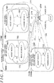
- the learning unit may be connected to the control unit via a network.
- the learning unit can be provided outside the walking assist device, and the user can be corrected into a more adequate walking state by performing learning based on more information that can be acquired from a plurality of walking assist devices.
- the X axis, the Y axis, and the Z axis in the drawings are orthogonal to each other.
- the Z-axis direction indicates the direction from a front wheel 60FR to a rear wheel 60RR
- the X-axis direction indicates the direction from the left to the right in a frame 50.
- the X-axis direction is referred to as "right”
- the direction opposite to the X-axis direction is referred to as "left”
- the direction opposite to the Z-axis direction is referred to as "front”
- the Z-axis direction is referred to as "rear”.
- the Y-axis direction is referred to as "upper”, and the direction opposite to the Y-axis direction is referred to as “lower”.
- the angular speed for rotation as seen in the X-axis direction is referred to as the pitch angular speed
- the angular speed for rotation as seen in the Y-axis direction is referred to as the yaw angular speed
- the angular speed for rotation as seen in the Z-axis direction is referred to as the roll angular speed.
- the magnitude of the angular speed for clockwise rotation as seen in the direction of each of the X axis, the Y axis, and the Z axis is defined as "positive", and the magnitude of the angular speed for counterclockwise rotation as seen in the direction of each of the X axis, the Y axis, and the Z axis is defined as "negative".
- FIG. 1 illustrates a walking assist device 10 according to the present embodiment.
- the walking assist device 10 has rails 30R and 30L (corresponding to the arm portion), a control unit 40, the frame 50, front wheels 60FR and 60FL, rear wheels 60RR and 60RL, drive units 64R and 64L (e.g. electric motors), a control panel 70, a battery B, and a regenerated power collecting unit 65.
- the frame 50 is shaped symmetrically in the right-left direction, and the rail 30R and the rail 30L are provided on the right side and the left side, respectively, of the frame 50 so as to extend along the front-rear direction of the frame 50.
- a user enters a space between the rail 30R and the rail 30L from the open side of the frame 50, and operates the walking assist device 10.
- the front wheels 60FR and 60FL are follower wheels (turnable caster wheels) provided at the lower front end of the frame 50.
- the frame 50 is provided with an outside temperature sensor 54 that detects an outside temperature, and a three-axis acceleration and angular speed sensor 52 that detects inclination of the walking assist device 10 in each of the X-axis direction, the Y-axis direction, and the Z-axis direction.
- the rear wheels 60RR and 60RL are drive wheels provided at the lower rear end of the frame 50, and are driven by the drive units 64R and 64L, respectively, via belts 62. In the example illustrated in FIG. 1 , a pair of right and left rear wheels are provided as the drive wheels, and are independently driven by the respective drive units.
- the rear wheels 60RR and 60RL can cause the walking assist device 10 to travel forward, travel rearward, make a right turn, and make a left turn.
- the rail 30R has a movable handle 20R (corresponding to the grasp portion) and a fixed handle 20FR (corresponding to the grasp portion) that can be grasped by the user.
- the rail 30L has a movable handle 20L (corresponding to the grasp portion) and a fixed handle 20FL (corresponding to the grasp portion) that can be grasped by the user.
- the movable handle 20R is provided on the rail 30R, and is movable in the front-rear direction along the rail 30R in accordance with swing of an arm during walk of the user.
- the movable handle 20L is provided on the rail 30L, and is movable in the front-rear direction along the rail 30L in accordance with swing of an arm during walk of the user.
- the rails 30R and 30L of the frame 50 are provided with the fixed handles 20FR and 20FL, respectively.
- the rails 30R and 30L are not limited to being shaped to be concavely curved upward, and may have a straight shape.
- control panel 70 is provided at a position at which the control panel 70 is easily operable by the user at the upper portion of the frame 50, for example.
- the control panel 70 has a main switch 72, an assist amount adjustment volume 74a, a load amount adjustment volume 74b, a manual mode switching unit 76a, an automatic mode switching unit switch 76b, and a monitor 78 (corresponding to the teaching information output unit).
- the walking assist device 10 has, as operation modes, a training mode, in which a load is applied to operation of the body of the user performed as the user walks, and an assist mode, in which the load on operation of the body of the user performed as the user walks is alleviated.
- the operation mode switching unit 76 has the manual mode switching unit 76a, the automatic mode switching unit switch 76b, and an automatic mode switching unit 76AT (see FIG. 7 ).
- the manual mode switching unit 76a switches the operation mode of the walking assist device 10 through a manual operation by the user.
- the manual mode switching unit 76a allows selection of one of two operation modes including an "assist mode" and a "training mode” (see FIG. 9 ).
- the automatic mode switching unit switch 76b is a switch that permits the control unit 40 to automatically switch the operation mode. In the case where the automatic mode switching unit switch 76b is on, the automatic mode switching unit 76AT of the control unit 40 automatically switches the operation mode based on information selected through the manual mode switching unit 76a and conditions in FIGS. 19 and 20 .
- the assist amount adjustment volume 74a is used to adjust the magnitude (assist amount) of an assist force in the assist mode.
- the load amount adjustment volume 74b is used to adjust the magnitude (load amount) of a load in the training mode.
- the monitor 78 has a sound output unit 78a and an image output unit 78b.
- the monitor 78 communicates, to the user, operation mode information and, besides, the charge amount of the battery B, a walking history, information on the body state of the user, a body information history of the user, a surrounding atmospheric state, a load amount and assist amount, an operation history of the walking assist device 10, a vehicle body state, for example, using at least one of the sound output unit 78a and the image output unit 78b.
- the monitor 78 also communicates teachings to the user by outputting at least one of a sound from the sound output unit 78a and an image from the image output unit 78b.
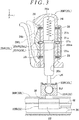
- FIG. 2 is a perspective view illustrating the configuration and the function of the movable handle 20R, the fixed handle 20FR, and the rail 30R.
- FIG. 3 is a sectional view of the movable handle 20R as seen in the III-III direction in FIG. 2 .
- FIG. 4 is a sectional view of the movable handle 20R as seen in the IV-IV direction in FIG. 2 .
- FIG. 5 is a perspective view of the fixed handle 20FR in FIG. 2 as enlarged.
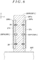
- FIG. 6 is a sectional view of the fixed handle 20FR as seen in the VI-VI direction in FIG. 5 .
- the rail 30R has the movable handle 20R, pulleys PB and PF, and a wire W.
- the rail 30R is shaped to be concavely curved upward, and has a rail slit portion 38 that opens upward, extends along the front-rear direction, and defines the movable range of the movable handle 20R.
- the rail 30R is provided with the pulleys PB and PF at respective ends in the front-rear direction.
- the wire W is wound around the pulley PF, which is provided on the front side, and the pulley PB, which is provided on the rear side, so that the pulleys PF and PB are rotated in conjunction with each other.
- a grasp portion drive unit 32R e.g.
- the wire is fixed to a wire connection portion WA of an anchor portion 22B, and the wire is inserted through a wire hole WH without being fixed.
- the movable handle 20R is connected to the anchor portion 22B. Consequently, the grasp portion drive unit 32R can assist movement of the movable handle 20R, or apply a load to movement of the movable handle 20R, by rotating the pulley PF to rotate the wire W between the pulleys PB and PF.
- the grasp portion position detection unit 34R outputs the amount of rotation of the pulley PF that accompanies movement of the movable handle 20R on the rail 30R to the control unit 40.
- the movable handle 20R has a handle shaft portion 21a, a shaft portion fitting hole 21b, a slider 22, a grip portion 26a, a switch grip portion 26b, and a brake lever BKL.
- the slider 22 is composed of a handle holding portion 22A and an anchor portion 22B.
- one end of an urging unit 24 is connected to the handle shaft portion 21a, and the other end thereof is connected to the bottom portion of the shaft portion fitting hole 21b.
- a flange portion 21c that extends in the circumferential direction is provided at the end portion of the handle shaft portion 21a to which the urging unit 24 is connected.
- An inner flange portion 20c is provided on an inside wall surface at an opening of the shaft portion fitting hole 21b. Consequently, the grip portion 26a is slidable up and down along the longitudinal direction of the handle shaft portion 21a without separating from the handle shaft portion 21a. That is, the movable handle 20R has an expansion and contraction mechanism that enables expansion and contraction in the projecting direction.
- a handle support shaft JK is provided on the side of the handle shaft portion 21a to which the urging unit 24 is not connected.
- the distal end of the handle support shaft JK is formed in a generally spherical shape, and forms a ball joint together with a recess provided in the handle holding portion 22A. Consequently, the movable handle 20R can be tilted to the front, rear, right, and left within a range defined by an opening with respect to the handle holding portion 22A (see FIGS. 3 and 4 ).
- a grasp portion inclination detection unit 33R that detects the amount of this tilt is provided at the opening of the handle holding portion 22A, and disposed on the front, rear, right, and left with respect to the handle support shaft JK.
- the grasp portion inclination detection unit 33R may be a pressure sensor that detects a pressure in accordance with expansion and contraction of springs provided between the side surfaces of the handle support shaft JK and the opening of the handle holding portion 22A, for example.
- the switch grip portion 26b is provided such that a predetermined gap is formed between the grip portion 26a and the switch grip portion 26b by grip urging units 28 (e.g. springs).
- grip urging units 28 e.g. springs
- a grasp portion pressure detection unit 25R has a grasp portion front pressure detection unit 25fR and a grasp portion rear pressure detection unit 25bR.
- the grasp portion pressure detection unit 25R measures a pressure input to the right movable handle 20R.
- a grasp portion pressure detection unit 25L has a grasp portion front pressure detection unit 25fL and a grasp portion rear pressure detection unit 25bL.
- the grasp portion pressure detection unit 25L measures a pressure input to the left movable handle 20L.
- the grasp portion front pressure detection units 25fR and 25fL and the grasp portion rear pressure detection units 25bR and 25bL are each a pressure sensor that detects a grasp portion pressure that is a pressure input to the movable handles 20R and 20L, respectively.
- the grasp portion front pressure detection units 25fR and 25fL and the grasp portion rear pressure detection units 25bR and 25bL may each be a load sensor that detects a load.
- the grasp portion front pressure detection unit 25fR detects a grasp portion front pressure that is a pressure directed forward and input to the corresponding right movable handle 20R.
- the grasp portion rear pressure detection unit 25bR detects a grasp portion rear pressure that is a pressure directed rearward and input to the corresponding right movable handle 20R.
- the grasp portion front pressure detection unit 25fL detects a grasp portion front pressure that is a pressure directed forward and input to the corresponding left movable handle 20L.
- the grasp portion rear pressure detection unit 25bL detects a grasp portion rear pressure that is a pressure directed rearward and input to the corresponding left movable handle 20L.
- the grasp portion front pressure detection unit 25fR outputs a signal that matches an applied pressure (see FIG. 3 ) with a switch grip portion 26ba moved toward the grip portion 26a when the user grasps the right movable handle 20R.
- the grasp portion front pressure detection unit 25fR is turned off when a pressure is not applied.
- the grasp portion front pressure detection unit 25fL outputs a signal that matches an applied pressure (see FIG. 3 ) with a switch grip portion 26ba moved toward the grip portion 26a when the user grasps the left movable handle 20L.
- the grasp portion front pressure detection unit 25fL is turned off when a pressure is not applied.
- the grasp portion rear pressure detection unit 25bR outputs a signal that matches an applied pressure (see FIG. 3 ) with the switch grip portion 26b moved toward the grip portion 26a when the user grasps the right movable handle 20R.
- the grasp portion rear pressure detection unit 25bR is turned off when a pressure is not applied.
- the grasp portion rear pressure detection unit 25bL outputs a signal that matches an applied pressure (see FIG. 3 ) with the switch grip portion 26b moved toward the grip portion 26a when the user grasps the left movable handle 20L.
- the grasp portion rear pressure detection unit 25bL is turned off when a pressure is not applied.
- a heart rate and body temperature sensor 27a is provided at a part of the grip portion 26a.
- the heart rate and body temperature sensor 27a measures the heart rate and the body temperature of the user in predetermined cycles in the case where the user grasps the movable handle 20R (20L).
- the heart rate of the user may be measured by measuring the blood flow at a portion grasped by his/her hand using infrared radiation, for example.
- the body temperature of the user may be measured by measuring variations in the resistance of a thermistor that is varied in accordance with temperature variations, or variations in infrared radiation emitted by the portion that is grasped by the user, for example.
- One end of the brake lever BKL is connected to the lower front side of the grip portion 26a.
- a mechanism that locks rotation of the front wheels 60FR and 60FL and the rear wheels 60RR and 60RL when the brake lever BKL is grasped and pulled toward the grip portion 26a by the user, that maintains the locked state, and unlocks such rotation when the brake lever BKL is further pulled is provided (not illustrated).
- the rail 30R is provided with the handle movement limiting unit 35R that permits and prohibits movement of the movable handle 20R with respect to the frame 50.
- the handle movement limiting unit 35R has a lock mechanism that locks rotation of the grasp portion drive unit 32R, for example.
- the handle movement limiting unit 35R prohibits movement of the handle by locking rotation of the grasp portion drive unit 32R, and permits movement of the handle with respect to the rail (i.e. with respect to the frame) by unlocking rotation of the grasp portion drive unit 32R.
- one end of the wire W is inserted through the wire hole WH that is provided in the anchor portion 22B, and the other end of the wire W is connected (fixed) to the wire connection portion WA.
- the movable handle 20R is movable on the rail 30R with a constricted portion that connects between the handle holding portion 22A and the anchor portion 22B sliding in the rail slit portion 38.
- a signal cable 36 transfers detection signals from the grasp portion pressure detection unit 25R and the grasp portion inclination detection unit 33R to the control unit 40 with one end of the signal cable 36 connected to the anchor portion 22B and with the other end thereof connected to the control unit 40.
- the signal cable 36 may be a cable that is flexible such as a flexible cable, for example.
- the control unit 40 can detect the position of the movable handle 20R on the rail 30R based on a detection signal from the grasp portion position detection unit 34R.
- the fixed handle 20FR (20FL) has a grip portion 26Fa and a switch grip portion 26Fb.
- a heart rate and body temperature sensor 27b measures the heart rate and the body temperature of the user in predetermined cycles in the case where the user grasps the fixed handle 20FR (20FL). Measurement of the heart rate and the body temperature of the user by the heart rate and body temperature sensor 27b is the same as that by the heart rate and body temperature sensor 27a, and therefore is not described.
- the switch grip portion 26Fb is provided such that a predetermined gap is formed between the grip portion 26Fa and the switch grip portion 26Fb by grip urging units 28 (e.g. springs).
- a grasp portion pressure detection unit 25FR outputs a detection signal that is proportional to a pressure with the switch grip portion 26Fb moved toward the grip portion 26Fa when the user grasps the fixed handle 20FR, and is turned off when a pressure is not applied.
- the grasp portion pressure detection unit 25FR may be any component that outputs a detection signal that is proportional to an applied pressure such as a pressure sensor, for example.
- FIG. 7 is a block diagram illustrating inputs and outputs of the control unit 40 (e.g. a control device that includes a CPU) of the walking assist device 10 (see FIG. 1 ).
- the control unit 40 receives, as inputs, information from a state detection unit 80, information stored in a storage unit 44, and information from the control panel 70.
- the control unit 40 controls the grasp portion drive units 32R and 32L (electric motors), the handle movement limiting units 35R and 35L, the drive units 64R and 64L, and the monitor 78 based on the input information.
- the control unit 40 has a grasp portion state observation unit 40a1, a walking state evaluation unit 40a2, a correction adjustment unit 40a3, a teaching information extraction unit 40a4, a determination data acquisition unit 40a5, and a learning unit 40a6.
- the state detection unit 80 is composed of a grasp portion state detection unit 81, a body state detection unit 82, a vehicle body state detection unit 83, and an atmospheric state detection unit 84.
- the grasp portion state detection unit 81 is composed of a movable handle acting force detection unit 81a, a movable handle movement amount detection unit 81b, and a fixed handle acting force detection unit 81c.
- the movable handle acting force detection unit 81a has the grasp portion pressure detection units 25R and 25L, the grasp portion inclination detection unit 33R, and a grasp portion inclination detection unit 33L.
- the grasp portion pressure detection unit 25R has the grasp portion front pressure detection unit 25fR and the grasp portion rear pressure detection unit 25bR (see FIG. 3 ).
- the grasp portion front pressure detection unit 25fR detects a grasping force applied to the front side of the movable handle 20R that is grasped by the user as a pressure (right grasp portion front pressure), and outputs a detection signal that matches the right grasp portion front pressure to the control unit 40.
- the grasp portion rear pressure detection unit 25bR detects a grasping force applied to the rear side of the movable handle 20R that is grasped by the user as a pressure (right grasp portion rear pressure), and outputs a detection signal that matches the right grasp portion rear pressure to the control unit 40.
- the grasp portion pressure detection unit 25L has the grasp portion front pressure detection unit 25fL and the grasp portion rear pressure detection unit 25bL (see FIG. 3 ).
- the grasp portion front pressure detection unit 25fL detects a grasping force applied to the front side of the movable handle 20L that is grasped by the user as a pressure (left grasp portion front pressure), and outputs a detection signal that matches the left grasp portion front pressure to the control unit 40.
- the grasp portion rear pressure detection unit 25bL detects a grasping force applied to the rear side of the movable handle 20L that is grasped by the user as a pressure (left grasp portion rear pressure), and outputs a detection signal that matches the left grasp portion rear pressure to the control unit 40.
- the grasp portion front pressure detection units 25fR and 25fL output a detection signal that matches a movable handle acting force (a force obtained by subtracting the grasp portion rear pressure from the grasp portion front pressure) to the control unit 40.
- the grasp portion inclination detection unit 33R detects how much (inclination angle) the movable handle 20R is tilted to which (inclination direction) of the front, rear, right, and left with respect to the rail 30R, and outputs the detected angle and direction to the control unit 40.
- the grasp portion inclination detection unit 33L detects how much (inclination angle) the movable handle 20L is tilted to which (inclination direction) of the front, rear, right, and left with respect to the rail 30L, and outputs the detected angle and direction to the control unit 40.
- the inclination direction is defined as "front” in the case where the movable handle (20R, 20L) is tilted to the front with respect to the frame 50, “rear” in the case where the movable handle (20R, 20L) is tilted to the rear, “right” in the case where the movable handle (20R, 20L) is tilted to the right, and “left” in the case where the movable handle (20R, 20L) is tilted to the left.
- the inclination direction is defined as “neutral” in the case where the movable handle (20R, 20L) is not tilted with respect to the frame 50.
- the inclination angle is detected as an angle with respect to the frame 50, for example.
- the movable handle movement amount detection unit 81b has the grasp portion position detection unit 34R and a grasp portion position detection unit 34L.
- the grasp portion position detection unit 34R detects a right grasp portion position HPR that is the position of the movable handle 20R on the rail 30R, and outputs a detection signal that matches the position to the control unit 40.
- the grasp portion position detection unit 34L detects a left grasp portion position HPL that is the position of the movable handle 20L on the rail 30L, and outputs a detection signal that matches the position to the control unit 40.
- the movable handle movement amount detection unit 81b detects the amount of movement, in a predetermined time, of the movable handles 20R and 20L with respect to the rails 30R and 30L (see FIG. 1 ) made as the user walks while grasping the movable handles 20R and 20L and swinging his/her arms, and outputs a signal that matches the detected amount to the control unit 40.
- the fixed handle acting force detection unit 81c has grasp portion pressure detection units 25FR and 25FL.
- the grasp portion pressure detection unit 25FR detects a fixed handle acting force that is a force to push forward and pull rearward the fixed handle 20FR (see FIG. 1 ) grasped by the user, and outputs a signal that matches a detected state to the control unit 40.
- the grasp portion pressure detection unit 25FL detects a fixed handle acting force that is a force to push forward and pull rearward the fixed handle 20FL (see FIG. 1 ) grasped by the user, and outputs a signal that matches a detected state to the control unit 40.
- the body state detection unit 82 is a unit that detects the body state of the user, and has heart rate and body temperature sensors 27a and 27b and a body information history 82a.
- the body state detection unit 82 detects the body state of the user, e.g. the heart rate and the body temperature of the user, through the heart rate and body temperature sensors 27a and 27b, and outputs a signal that matches the detected state to the control unit 40.
- the body state detection unit 82 stores a history of body information (e.g. the heart rate, the body temperature, and the number of footsteps) on the user in the body information history 82a.
- the number of footsteps is calculated based on information from the movable handle movement amount detection unit 81b by determining that the user makes two steps when he/she swings his/her arms back and forth once in the front-rear direction, for example.
- the vehicle body state detection unit 83 is a unit that detects the state of the walking assist device 10 including an operation history of the walking assist device 10, and has a travel speed acquisition unit 56R, a travel speed acquisition unit 56L, the three-axis acceleration and angular speed sensor 52, and operation history information 58.
- the travel speed acquisition unit 56R and the travel speed acquisition unit 56L are connected to the drive units 64R and 64L, respectively, and output a detection signal corresponding to travel speeds (VdR and VdL) at which the rear wheels 60RR and 60RL (see FIG. 1 ) travel forward and rearward, respectively, to the control unit 40.
- the three-axis acceleration and angular speed sensor 52 measures an acceleration for each of the axes in the three directions, namely the X axis, the Y axis, and the Z axis, and measures an angular speed of rotation about each of the axes in the three directions.
- the three-axis acceleration and angular speed sensor 52 outputs a detection signal that matches the tilt of the vehicle with respect to the inclined surface for each of the X axis, the Y axis, and the Z axis to the control unit 40.
- the three-axis acceleration and angular speed sensor 52 also detects variations in the acceleration applied to the vehicle body of the walking assist device 10 (impact on the vehicle body), and outputs a signal that matches the detected variations in the acceleration to the control unit 40.
- the three-axis acceleration and angular speed sensor 52 also detects the pitch angular speed, the yaw angular speed, and the roll angular speed of the vehicle body of the walking assist device 10, and outputs a signal that matches the detected angular speeds to the control unit 40.
- the three-axis acceleration and angular speed sensor 52 also functions as a turning force measurement unit that detects a device turning force (yaw angular speed) that is a force that turns the walking assist device 10, and outputs a signal that matches the detected yaw angular speed to the control unit 40.
- a device turning force yaw angular speed
- the vehicle body state detection unit 83 stores an operation history (e.g. the walking distance and the walking time) of the walking assist device 10 in the operation history information 58, and detects the state of the walking assist device 10 (e.g. the travel speed of the walking assist device, the tilt of the vehicle body, and the travel speed).
- an operation history e.g. the walking distance and the walking time
- the state of the walking assist device 10 e.g. the travel speed of the walking assist device, the tilt of the vehicle body, and the travel speed.
- the atmospheric state detection unit 84 is a unit that detects the atmospheric state (e.g. the outside temperature) around the user, and has the outside temperature sensor 54.
- the atmospheric state detection unit 84 detects the outside temperature through the outside temperature sensor 54, and outputs a signal that matches the detected state to the control unit 40.
- the control unit 40 calculates forward-direction evaluation speeds (VRhf and VLhf), which are speeds of movement in the forward direction of the movable handles 20R and 20L with respect to the frame 50, and rearward-direction evaluation speeds (VRhb and VLhb), which are speeds of movement in the rearward direction of the movable handles 20R and 20L with respect to the frame 50, based on the amounts of movement of the movable handles 20R and 20L (see FIGS. 1 and 2 ).
- the magnitude of the speeds of movement of the movable handles 20R and 20L with respect to the frame 50 is defined as "positive" in the case of movement in the forward direction, and defined as “negative” in the case of movement in the rearward direction.
- the forward-direction evaluation speeds (VRhf and VLhf), or the rearward-direction evaluation speeds (VRhb and VLhb), are calculated through integration from the speeds of movement of the movable handles (20R and 20L) for a case where the user swings his arm forward, or rearward, for example.
- the evaluation speed is derived in accordance with the following procedure. The processes are the same for the right and left movable handles, and therefore only the forward-direction evaluation speed (VRhf) and the rearward-direction evaluation speed (VRhb) of the right movable handle 20R will be described.
- the control unit 40 calculates the speed of movement of the movable handle 20R based on the amount of movement of the movable handle 20R measured at predetermined intervals.
- the control unit 40 integrates (integration process) only the speeds of forward movement (speeds of movement having a "positive" magnitude) at which the movable handle 20R moves forward, among the calculated speeds (right grasp portion movement speeds) of movement of the movable handle 20R.
- the control unit 40 derives the forward-direction evaluation speed (VRhf) by dividing the speed of forward movement of the movable handle 20R, which is obtained through integration, by a predetermined time (averaging process).
- the control unit 40 calculates the speed of movement of the movable handle 20R based on the amount of movement of the movable handle 20R measured at predetermined intervals.
- the control unit 40 integrates (integration process) only the speeds of rearward movement (speeds of movement having a "negative" magnitude) at which the movable handle 20R moves rearward, among the calculated speeds (right grasp portion movement speeds) of movement of the movable handle 20R.
- the control unit 40 derives the rearward-direction evaluation speed (VRhb) by dividing the speed of rearward movement of the movable handle 20R, which is obtained through integration, by a predetermined time (averaging process).
- the control unit 40 drives the rear wheels 60RR and 60RL, which are drive wheels, by controlling the drive units 64R and 64L so as to achieve target travel speeds (VR and VL) that are targets for travel of the walking assist device 10.
- the target travel speed VR is a target travel speed at which the rear wheel 60RR of the walking assist device 10 is caused to travel based on operation by the user
- the target travel speed VL is a target travel speed at which the rear wheel 60RL of the walking assist device 10 is caused to travel based on operation by the user (see FIG. 1 ).
- the control unit 40 drives the movable handles 20R and 20L (see FIG. 2 ) by controlling the grasp portion drive units 32R and 32L so as to achieve target movement speeds (UR and UL).
- the target movement speed UR is calculated based on the speed at which the user moves the movable handle 20R on the rail 30R (see FIG. 2 ).
- the target movement speed UL is calculated based on the speed at which the user moves the movable handle 20L on the rail 30L (see FIG. 2 ).
- the target movement speeds are each set to a speed that serves as a load on the grasp portion movement speed (right grasp portion movement speed, left grasp portion movement speed) in the case where a load is to be imposed on the movable handle, and set to a speed that assists the grasp portion movement speed in the case where the movable handle is to be assisted.
- a load amount and assist amount change unit 74 has the assist amount adjustment volume 74a and the load amount adjustment volume 74b.
- the assist amount adjustment volume 74a outputs a detection signal that matches the adjustment amount (assist adjustment amount) for adjusting the magnitude (assist amount) of an assist force in the assist mode to the control unit 40.
- the load amount adjustment volume 74b outputs a detection signal that matches the adjustment amount (load adjustment amount) for adjusting the magnitude (load amount) of a load in the training mode to the control unit 40.
- the load amount and assist amount change unit 74 changes the assist amount based on information from the state detection unit 80 and the assist adjustment amount.
- the load amount and assist amount change unit 74 changes the load amount based on information from the state detection unit 80 and the load adjustment amount.
- the storage unit 44 is a unit that stores information, and stores and reads information in response to a request from the control unit 40.
- the storage unit 44 stores information such as information acquired by the state detection unit 80, the result of computation performed by the control unit 40, the operation history of the walking assist device 10, the assist amount in the assist mode in the past during walk of the user, and the load amount in the training mode.
- the storage unit 44 stores reference stroke information including a reference stroke length that matches user personal information including gender, age, and body information of the user.
- the storage unit 44 also stores teaching information including teachings about a correction of the walking state of the user.
- the control panel 70 provides switches and the monitor 78 that are necessary for the user to operate the walking assist device 10.
- the user makes the walking assist device 10 ready for travel by turning on the main switch 72.
- the user can adjust the load amount in the training mode and the assist amount in the assist mode using the assist amount adjustment volume 74a and the load amount adjustment volume 74b.
- the user can select a desired operation mode ("assist mode” and "training mode") by operating the manual mode switching unit 76a.
- the control unit 40 automatically switches the operation mode between the operation mode selected by the user and a predetermined operation mode.
- FIG. 8 is a state transition diagram illustrating the operation modes of the walking assist device 10 determined based on outputs of the various detection units.
- FTG. 9 illustrates conditions for transitioning from a determination mode JDM to various operation modes in FIG. 8 and conditions for returning to the determination mode JDM.
- FIG. 10 is a flowchart illustrating the procedure of the overall process for the control unit 40 of the walking assist device 10.
- FIG. 8 illustrates the operation modes of the walking assist device 10 determined based on outputs of the various detection units.
- the walking assist device 10 has operation modes including the determination mode JDM, an assist mode 1 (AM1), an assist mode 2 (AM2), an assist mode 3 (AM3), a training mode 1 (TR1), a training mode 2 (TR2), and a training mode 3 (TR3).
- AM1 assist mode 1
- AM2 assist mode 2
- AM3 assist mode 3
- TR1 training mode 1
- TR2 training mode 2
- TR3 training mode 3
- the control unit 40 When the main switch 72 (see FIG. 7 ) is turned on (power is turned on), the control unit 40 reads the operation history stored in the storage unit 44, and writes the operation history into the operation history information 58. After that, the control unit 40 causes the walking assist device 10 to transition to the determination mode JDM. After a transition to the determination mode JDM, the control unit 40 acquires each state through the state detection unit 80, and causes the walking assist device 10 to transition to an operation mode based on the acquired state. When the main switch 72 is turned off (power is turned off), the control unit 40 stores information (e.g. the walking distance and the walking time) about the operation history in the operation history information 58 in the storage unit 44, and finishes the operation.
- information e.g. the walking distance and the walking time
- the operation modes include a fixed handle grasping mode FXHM and a movable handle grasping mode FRHM.
- FXHM fixed handle grasping mode
- FRHM movable handle grasping mode
- the user walks while causing the walking assist device 10 to travel by grasping the movable handles 20R and 20L (see FIG. 1 ).
- the movable handle grasping mode FRHM includes a no-arm-swing walking mode NHM1, in which the user grasps the movable handles 20R and 20L but does not swing his/her arms, and an arm-swing walking mode YHM, in which the user swings his/her arms.
- the fixed handle grasping mode FXHM in which the user grasps the fixed handles 20FR and 20FL, is a no-arm-swing walking mode NHM2.
- the no-arm-swing walking mode NHM1 of the movable handle grasping mode FRHM in which the user grasps the movable handles 20R and 20L that are fixed at a predetermined position on the rails 30R and 30L (see FIG. 1 ), corresponds to the fixed handle grasping mode FXHM (no-arm-swing walking mode NHM2).
- the arm-swing walking mode YHM the user walks while causing the walking assist device 10 to travel by grasping the movable handles 20R and 20L and moving the movable handles 20R and 20L along the front-rear direction of the rails 30R and 30L.
- the arm-swing walking mode YHM of the movable handle grasping mode FRHM includes the training mode 1 (TR1) and the assist mode 1 (AM1).
- the no-arm-swing walking mode NHM1 of the movable handle grasping mode FRHM includes the assist mode 2 (AM2) and the training mode 2 (TR2).
- the fixed handle grasping mode FXHM includes the assist mode 3 (AM3) and the training mode 3 (TR3).
- the load on operation of the body of the user of the walking assist device 10 can be alleviated.
- the movable handles 20R and 20L can be moved by the grasp portion drive units 32R and 32L applying an assist force that is larger by a predetermined amount than an assist force with which operation (arm swing) of the body of the user performed as the user walks is operation (arm swing) in a no-load state to movement of the movable handles 20R and 20L in the front-rear direction.
- the walking assist device 10 can be caused to travel with an assist force that is larger by a predetermined amount than an assist force with which operation (walk) of the body of the user performed as the user walks is operation (walk) in a no-load state. Consequently, the load on operation (walk, arm swing) of the body of the user performed as the user walks can be alleviated.
- the load on operation of the body of the user of the walking assist device 10 can be alleviated.
- the walking assist device 10 can be caused to travel with an assist force that is larger by a predetermined amount than an assist force with which operation (walk) of the body of the user performed as the user walks is operation (walk) in a no-load state. Consequently, the load on operation (walk) of the body of the user performed as the user walks can be alleviated.
- the walking assist device 10 In the training mode 1 (TR1), the walking assist device 10 is caused to travel while causing the regenerated power collecting unit 65 to operate.
- the regenerated power collecting unit 65 is connected to the rear wheels 60RR and 60RL (see FIG. 1 ), and converts rotational energy into electric power to be collected (see FIGS. 1 and 7 ).
- the walking assist device 10 In the training mode 1 (TR1), the walking assist device 10 can be caused to travel by applying a load to movement of the movable handles 20R and 20L in the front-rear direction through the grasp portion drive units 32R and 32L. Consequently, a load can be applied to operation (walk, arm swing) of the body of the user performed as the user walks.
- the walking assist device 10 In the training mode 2 (TR2), the walking assist device 10 is caused to travel while causing the regenerated power collecting unit 65 to operate. Thus, it is necessary for the user to push or pull the walking assist device 10 with a stronger force than in the assist mode 2 (AM2) in order to cause the walking assist device 10 to travel. Consequently, a load can be applied to operation (walk) of the body of the user performed as the user walks.
- the walking assist device 10 In the training mode 3 (TR3), the walking assist device 10 is caused to travel while causing the regenerated power collecting unit 65 to operate. Thus, it is necessary for the user to push or pull the walking assist device 10 with a stronger force than in the assist mode 3 (AM3) in order to cause the walking assist device 10 to travel. Consequently, a load can be applied to operation (walk) of the body of the user performed as the user walks.
- FIG. 9 illustrates conditions for transitioning from the determination mode JDM to various operation modes in FIG. 8 and conditions for returning to the determination mode JDM.
- conditions C1 to C6 are conditions for transitioning from the determination mode JDM to the various operation modes in FIG. 8
- conditions CR1 to CR6 are conditions for returning from the various operation modes to the determination mode JDM.
- the symbol "-" indicates that the state may be either "0" or "1".
- a transition to the various operation modes is determined in accordance with the manual mode switching unit 76a (see FIG. 7 ), the state (see FIG. 1 ) of the movable handles (20R and 20L), and the state (see FIG. 1 ) of the fixed handles (20FR and 20FL).
- the conditions for transitioning from the various operation modes to the determination mode JDM are determined in accordance with the current operation mode, the state of the movable handles (20R and 20L), and the state of the fixed handles (20FR and 20FL).
- control unit 40 changes the operation mode to an operation mode corresponding to the condition. Determination of a transition from the determination mode JDM to the various operation modes will be described in detail below.
- the control unit 40 causes the operation mode to transition from the determination mode JDM to the assist mode 1 (AM1).
- the control unit 40 causes the operation mode to transition from the determination mode JDM to the assist mode 2 (AM2).
- the control unit 40 causes the operation mode to transition from the determination mode JDM to the assist mode 3 (AM3).
- the control unit 40 causes the operation mode to transition from the determination mode JDM to the training mode 1 (TR1).
- the control unit 40 causes the operation mode to transition from the determination mode JDM to the training mode 2 (TR2).
- the control unit 40 causes the operation mode to transition from the determination mode JDM to the training mode 3 (TR3).
- the control unit 40 finishes the current operation mode (see FIG. 8 ), and causes the operation mode to transition to the determination mode JDM. Determination of a transition from the various operation modes to the determination mode JDM will be described in detail below.
- the control unit 40 causes the operation mode to transition from the assist mode 1 (AM1) to the determination mode JDM.
- the control unit 40 causes the operation mode to transition from the assist mode 2 (AM2) to the determination mode JDM.
- the control unit 40 causes the operation mode to transition from the assist mode 3 (AM3) to the determination mode JDM.
- the control unit 40 causes the operation mode to transition from the training mode 1 (TR1) to the determination mode JDM.
- the control unit 40 causes the operation mode to transition from the training mode 2 (TR2) to the determination mode JDM.
- the condition CR6 is met irrespective of the other states, and the control unit 40 causes the operation mode to transition from the training mode 3 (TR3) to the determination mode JDM.
- FIG. 10 is a flowchart illustrating the procedure of the overall process for the control unit 40 (see FIG. 7 ) of the walking assist device 10 (see FIG. 1 ).
- the process procedure for the control unit 40 of the walking assist device 10 will be described with reference to the flowchart in FIG. 10 .
- the operation mode in each process is not given the symbol in FTG. 8 except where it is necessary for convenience of description.
- the overall process for the control unit 40 is constituted from: processes for calculation of target movement speeds for the movable handles and calculation of a target travel speed at which the walking assist device 10 is caused to travel (steps S10 to SUB400); teaching by the teaching information output unit (step S35); and processes for drive of the movable handles and drive of the drive wheels (steps S40 and S50).
- the control unit 40 executes the overall process at intervals of a predetermined time (e.g. at intervals of several milliseconds) when started.
- step S10 the control unit 40 acquires information (detection signal) from the various detection units (grasp portion state detection unit 81, body state detection unit 82, vehicle body state detection unit 83, and atmospheric state detection unit 84) (see FIG. 7 ), calculates forward-direction evaluation speeds VRhf and VLhf and rearward-direction evaluation speeds VRhb and VLhb, and proceeds to step S15.
- information detection signal
- step S15 the grasp portion state observation unit 40a1 observes a grasp portion state, which is the state of each of the movable handles (20R and 20L), based on the detection signal from the grasp portion state detection unit 81, and proceeds to step S20.
- step S20 determination of the operation mode based on each acquired state
- the control unit 40 reads each state acquired through the state detection unit 80 (see FIG. 7 ) and stored in the storage unit 44, determines the operation mode (see FIG. 8 ) for which the condition is met in accordance with FIG. 9 based on such information, and proceeds to step SUB100.
- step SUB200 the walking state evaluation unit 40a2 (see FIG. 7 ) evaluates the walking state of the user based on the grasp portion state observed using the grasp portion state observation unit 40a1, and proceeds to step S30.
- step S30 the control unit 40 proceeds to step SUB400 (process for adjusting control commands and teaching information by the learning unit) in the case where it is determined that a learning unit switch 72a (see FIGS. 1 and 3 ) is turned on (Yes), and proceeds to step SUB300 (adjustment for correcting control commands) in the case where it is determined that the learning unit switch 72a is not turned on (No).
- step SUB400 process for adjusting control commands and teaching information by the learning unit
- step SUB300 the correction adjustment unit 40a3 (see FIG. 7 ) adjusts control commands for the grasp portion drive units 32R and 32L based on the walking state (step SUB200) that is evaluated using the walking state evaluation unit 40a2, and proceeds to step S35 (teaching by the teaching information output unit).
- step SUB400 the learning unit 40a6 (see FIG. 7 ) learns the control commands that are adjusted by the correction adjustment unit 40a3 and the teaching information that is extracted by the teaching information extraction unit 40a4 (see FIG. 7 ) in accordance with a training data set constituted of a combination of a state variable and determination data, and proceeds to step S35 (teaching by the teaching information output unit).
- the state variable is a variable that indicates the state of the user and that includes at least one of the respective positions (right grasp portion position HPR and left grasp portion position HPL) of the movable handles 20R and 20L with respect to the respective rails 30R and 30L, the respective inclination directions and inclination angles of the movable handles 20R and 20L with respect to the respective rails 30R and 30L, and the respective pressures (right grasp portion front pressure, right grasp portion rear pressure, left grasp portion front pressure, and left grasp portion rear pressure) applied to the movable handles 20R and 20L.
- the determination data are data for determining the deviation between a target walking state, which is based on a reference walking state that is a walking state serving as a reference for the user, and the actual walking state of the user and fluctuations in the actual walking state of the user.
- step S35 the teaching information extraction unit 40a4 extracts teaching information corresponding to the walking state that is evaluated in step SUB200 from the storage unit 44, outputs a sound and an image corresponding to the extracted teaching information from the monitor 78 (teaching information output unit) (see FIG. 7 ), and proceeds to step S40.
- step S40 the control unit 40 drives the grasp portion drive units 32R and 32L so as to bring the movement speeds of the movable handles (20R and 20L) to the target movement speeds (UR and UL), and proceeds to step S50.
- step S50 the control unit 40 drives the rear wheels 60RR and 60RL by controlling the drive units 64R and 64L such that the target travel speeds (VR and VL) for the walking assist device 10 are set to target forward travel speeds (VfdR and VfdL), which are the target travel speeds for forward travel, in the case of forward travel, set to target reverse travel speeds (VbdR and VbdL), which are the target travel speeds for reverse travel, in the case of reverse travel, and set to "0" otherwise, and finishes the overall process.
- target travel speeds VR and VL
- VfdR and VfdL target travel speeds for forward travel, in the case of forward travel
- VbdR and VbdL target reverse travel speeds
- Step S10 acquisition of information from each detection unit
- step S10 the control unit 40 acquires information (detection signal) from the state detection unit 80 (grasp portion state detection unit 81, body state detection unit 82, vehicle body state detection unit 83, and atmospheric state detection unit 84), and stores a variety of detected states (input states) in the storage unit 44.
- the control unit 40 calculates forward-direction evaluation speeds VRhf and VLhf and rearward-direction evaluation speeds VRhb and VLhb based on the information acquired through the state detection unit 80, and stores such evaluation speeds in the storage unit 44.
- the control unit 40 finishes the acquisition of each state through the state detection unit (step S10), and returns to the overall process.
- control unit 40 detects and stores the following input states in the storage unit 44 in step S10.
- the grasp portion state (state of the fixed handles 20FR and 20FL and the movable handles 20R and 20L) includes the following.
- the body state of the user includes the following.
- the vehicle body state of the walking assist device 10 includes the following.
- the surrounding atmospheric state includes the following.
- the output information from the control panel 70 includes the following.
- Step S15 observation of the grasp portion state by the grasp portion state observation unit
- the grasp portion state observation unit 40a1 observes the following grasp portion state, which is the state of the movable handles 20R and 20L (grasp portions), based on the detection signal from the grasp portion state detection unit 81. Observed values as the observed grasp portion state and calculated values calculated based on the observed values are stored in the storage unit 44.
- the grasp portion state observation unit 40a1 evaluates the walking state based on the grasp portion state during a period excluding a predetermined post-start period, which is a predetermined period immediately after the user starts walking using the walking assist device 10, a predetermined pre-end period, which is a predetermined period immediately before the user finishes walking using the walking assist device 10, and a predetermined turn period, which is a predetermined period before and after a right turn or a left turn made by the user using the walking assist device 10.
- the state about the grasp portion pressure includes the following.
- the state about the inclination of the grasp portion includes the following.
- the state about the position and the speed of the grasp portion includes the following.
- the state about the stroke of the grasp portion includes the following.
- the grasp portion state observation unit 40a1 observes the grasp portion state during a predetermined observation period (predetermined time, predetermined number of times of arm swing), and stores the observed state in the storage unit 44.
- the grasp portion state observation unit 40a1 calculates the average grasp portion state based on the stored grasp portion state.
- the grasp portion state observation unit 40a1 observes, as the state variable, at least one of the respective positions (right grasp portion position HPR and left grasp portion position HPL) of the movable handles 20R and 20L with respect to the respective rails 30R and 30L, the respective inclination directions and inclination angles of the movable handles 20R and 20L with respect to the respective rails 30R and 30L, and the respective pressures (right grasp portion front pressure, right grasp portion rear pressure, left grasp portion front pressure, and left grasp portion rear pressure) applied to the movable handles 20R and 20L.
- FIG. 11A and FIG. 11B are flowcharts illustrating processes in determined operation modes.
- the control unit 40 performs processes in the determined operation mode based on the result of the determination that is made in step S20 (determination of the operation mode based on each acquired state).
- step S110 the control unit 40 proceeds to step S300 in the case where the determined operation mode is the assist mode 3 (AM3) (Yes), and proceeds to step S120 in the case where the determined operation mode is not the assist mode 3 (AM3) (No).
- step S120 the control unit 40 proceeds to step S400 in the case where the determined operation mode is the training mode 3 (TR3) (Yes), and proceeds to step S130 in the case where the determined operation mode is not the training mode 3 (TR3) (No).
- step S130 the control unit 40 proceeds to step S500 in the case where the determined operation mode is the assist mode 2 (AM2) (Yes), and proceeds to step S140 in the case where the determined operation mode is not the assist mode 2 (AM2) (No).
- step S140 the control unit 40 proceeds to step S600 in the case where the determined operation mode is the training mode 2 (TR2) (Yes), and proceeds to step S150 in the case where the determined operation mode is not the training mode 2 (TR2) (No).
- step S150 the control unit 40 proceeds to step S700 in the case where the determined operation mode is the training mode 1 (TR1) (Yes), and proceeds to step S160 in the case where the determined operation mode is not the training mode 1 (TR1) (No).
- step S160 the control unit 40 proceeds to step S800 in the case where the determined operation mode is the assist mode 1 (AM1) (Yes), and proceeds to step S170 in the case where the determined operation mode is not the assist mode 1 (AM1) (No).
- step S170 the control unit 40 sets the target travel speed for the walking assist device 10 to 0 (determination mode), and returns to the overall process.
- FIG. 12 is a flowchart illustrating the procedure of processes in the assist mode 3 (AM3) in the control unit 40 of the walking assist device 10 (see FIGS. 1 , 7 , and 8 ).
- Step S300 processing in the assist mode 3 will be described with reference to the flowchart in FIG. 12 .
- step S310 the control unit 40 proceeds to step S320 in the case where the acting force of the user applied to the fixed handles 20FR and 20FL is in the forward direction (Yes) based on information from the fixed handle acting force detection unit 81c, and proceeds to step S330 in the case where the acting force of the user applied to the fixed handles 20FR and 20FL is not in the forward direction (No).
- step S320 the control unit 40 calculates the target forward travel speeds (VfdR and VfdL) that match the acting force applied to the fixed handles 20FR and 20FL and the assist amount that is derived by the load amount and assist amount change unit 74, finishes the processes in the assist mode 3 (step S300), and returns to the overall process.
- VfdR and VfdL target forward travel speeds
- step S330 the control unit 40 calculates the target rearward travel speeds (VbdR and VbdL) that match the acting force applied to the fixed handles 20FR and 20FL and the assist amount that is derived by the load amount and assist amount change unit 74, finishes the processes in the assist mode 3 (step S300), and returns to the overall process.
- VbdR and VbdL target rearward travel speeds
- the walking assist device 10 can be caused to travel with an assist force that is larger by a predetermined amount than an assist force with which operation (walk) of the body of the user performed as the user walks is operation in a no-load state. Consequently, the load on operation (walk) of the body of the user performed as the user walks can be alleviated.
- FIG. 12 is a flowchart illustrating the procedure of processes in the training mode 3 (TR3) in the control unit 40 of the walking assist device 10 (see FIGS. 1 , 7 , and 8 ).
- Step S400 processings in the training mode 3 will be described with reference to the flowchart in FIG. 12 .
- the walking assist device 10 is not caused to generate an assist force for the acting force of the user with the regenerated power collecting unit 65 operating.
- step S410 the control unit 40 proceeds to step S420 in the case where the acting force of the user applied to the fixed handles 20FR and 20FL is in the forward direction (Yes) based on information from the fixed handle acting force detection unit 81c, and proceeds to step S430 in the case where the acting force of the user applied to the fixed handles 20FR and 20FL is not in the forward direction (No).
- step S420 the control unit 40 calculates the target forward travel speeds (VfdR and VfdL) that match the acting force applied to the fixed handles 20FR and 20FL, finishes the processes in the training mode 3 (step S400), and returns to the overall process.
- VfdR and VfdL target forward travel speeds
- step S430 the control unit 40 calculates the target rearward travel speeds (VbdR and VbdL) that match the acting force applied to the fixed handles 20FR and 20FL, finishes the processes in the training mode 3 (step S400), and returns to the overall process.
- VbdR and VbdL target rearward travel speeds
- FIG. 13A and FIG. 13B are flowcharts illustrating the procedure of processes in the assist mode 2 (AM2) in the control unit 40 of the walking assist device 10 (see FIGS. 1 , 7 , and 8 ).
- Step S500 processings in the assist mode 2 will be described with reference to the flowchart in FIG. 13A and FIG. 13B .
- step S510 the control unit 40 fixes the movable handles 20R and 20L at predetermined positions by limiting movement thereof on the rails 30R and 30L due to drive of the grasp portion drive units 32R and 32L using the handle movement limiting units 35R and 35L, and proceeds to step S515.
- step S520 the control unit 40 proceeds to step S530 in the case where the acting force of the user applied to the movable handles 20R and 20L is in the forward direction (Yes) based on information from the movable handle acting force detection unit 81a, and proceeds to step S540 in the case where the acting force of the user applied to the movable handles 20R and 20L is not in the forward direction (No).
- step S530 the control unit 40 calculates the target forward travel speeds (VfdR and VfdL) that match the acting force applied to the movable handles 20R and 20L and the assist amount that is derived by the load amount and assist amount change unit 74, finishes the processes in the assist mode 2 (step S500), and returns to the overall process.
- VfdR and VfdL target forward travel speeds
- step S540 the control unit 40 calculates the target rearward travel speeds (VbdR and VbdL) that match the acting force applied to the movable handles 20R and 20L and the assist amount that is derived by the load amount and assist amount change unit 74, finishes the processes in the assist mode 2 (step S500), and returns to the overall process.
- VbdR and VbdL target rearward travel speeds
- the walking assist device 10 can be caused to travel with an assist force that is larger by a predetermined amount than an assist force with which operation (walk) of the body of the user performed as the user walks is operation in a no-load state. Consequently, the load on operation (walk) of the body of the user performed as the user walks can be alleviated.
- FIG. 13A and FIG. 13B are flowcharts illustrating the procedure of processes in the training mode 2 (TR2) in the control unit 40 of the walking assist device 10 (see FIGS. 1 , 7 , and 8 ).
- Step S600 processings in the training mode 2 will be described with reference to the flowchart in FIG. 13A and FIG. 13B .
- the walking assist device 10 is not caused to generate an assist force in accordance with the acting force of the user with the regenerated power collecting unit 65 operating.
- step S610 the control unit 40 fixes the movable handles 20R and 20L at predetermined positions by limiting movement thereof on the rails 30R and 30L due to drive of the grasp portion drive units 32R and 32L using the handle movement limiting units 35R and 35L, and proceeds to step S615.
- step S620 the control unit 40 proceeds to step S630 in the case where the acting force of the user applied to the movable handles 20R and 20L is in the forward direction (Yes) based on information from the movable handle acting force detection unit 81a, and proceeds to step S640 in the case where the acting force of the user applied to the movable handles 20R and 20L is not in the forward direction (No).
- step S630 the control unit 40 calculates the target forward travel speeds (VfdR and VfdL) that match the acting force applied to the movable handles 20R and 20L, finishes the processes in the training mode 2 (step S600), and returns to the overall process.
- VfdR and VfdL target forward travel speeds
- step S640 the control unit 40 calculates the target rearward travel speeds (VbdR and VbdL) that match the acting force applied to the movable handles 20R and 20L, finishes the processes in the training mode 2 (step S600), and returns to the overall process.
- VbdR and VbdL target rearward travel speeds
- FIG. 14A and FIG. 14B are flowcharts illustrating the procedure of processes in the training mode 1 (TR1) in the control unit 40 of the walking assist device 10 (see FIGS. 1 , 7 , and 8 ).
- Step S700 processings in the training mode 1 will be described with reference to the flowchart in FIG. 14A and FIG. 14B .
- An assist force is not generated for the acting force of the user with the regenerated power collecting unit 65 operating.
- the speed coefficient kL1 is a speed coefficient ( ⁇ 1) for applying a load with a load amount derived by the load amount and assist amount change unit 74 to movement of the movable handles 20R and 20L.
- step S706 the control unit 40 proceeds to step S1200 (determination of the direction of a device turning force) in the case where both the right movable handle 20R and the left movable handle 20L are moved, that is, both the right and left arms are swung (Yes), based on information from the movable handle movement amount detection unit 81b, and proceeds to step S1300 (determination of a turn) in the case where both the right and left arms are not swung (No).
- step S708 the control unit 40 proceeds to step S710 in the case where the direction of the device turning force of the walking assist device 10 is "right” (Yes), and proceeds to step S712 in the case where the direction of the device turning force of the walking assist device 10 is not “right” (No).
- ⁇ V ⁇ is a predetermined speed corresponding to the magnitude of the device turning force (yaw angular speed), and is stored in the storage unit 44 in advance. Consequently, the device turning force toward the right is reduced by making the rotational speed of the right rear wheel 60RR higher than the rotational speed of the left rear wheel 60RL.
- step S712 the control unit 40 proceeds to step S714 in the case where the direction of the device turning force of the walking assist device 10 is "left” (Yes), and proceeds to step S716 in the case where the direction of the device turning force of the walking assist device 10 is not "left” (No).
- step S716 the control unit 40 proceeds to step S718 in the case where the direction of the device turning force of the walking assist device 10 is "front” (Yes), and proceeds to step S720 in the case where the direction of the device turning force of the walking assist device 10 is not "front” (No).
- step S742 the control unit 40 proceeds to step S744 in the case where the travel direction of the walking assist device 10 is "left turn A" (Yes), and proceeds to step S746 in the case where the travel direction of the walking assist device 10 is not "left turn A” (No).
- ⁇ Vr is a predetermined speed corresponding to the travel speeds (VdR and VdL), and is stored in the storage unit 44 in advance.
- step S746 the control unit 40 proceeds to step S748 in the case where the travel direction of the walking assist device 10 is "right turn A" (Yes), and proceeds to step S750 in the case where the travel direction of the walking assist device 10 is not "right turn A” (No).
- step S750 the control unit 40 proceeds to step S752 in the case where the travel direction of the walking assist device 10 is "left turn B" (Yes), and proceeds to step S754 in the case where the travel direction of the walking assist device 10 is not "left turn B" (No).
- step S754 the control unit 40 proceeds to step S756 in the case where the travel direction of the walking assist device 10 is "right turn B" (Yes), and proceeds to step S758 in the case where the travel direction of the walking assist device 10 is not "right turn B" (No).
- step S722 the control unit 40 proceeds to step S724 in the case where the travel speed of the walking assist device 10 is equal to the walking speed of the user (Yes), and proceeds to step S726 in the case where the travel speed of the walking assist device 10 is not equal to the walking speed of the user (No).
- step S726 the control unit 40 proceeds to step S728 in the case where the travel speed of the walking assist device 10 is lower than the walking speed of the user (Yes), and proceeds to step S730 in the case where the travel speed of the walking assist device 10 is not lower than the walking speed of the user (No).
- ⁇ Vd is a predetermined speed corresponding to the magnitude of the target travel speeds (VdR' and VdL') for correcting the target travel speeds, and is stored in the storage unit 44 in advance.
- the walking assist device 10 can be caused to travel by applying a load to movement of the movable handles 20R and 20L in the front-rear direction through the grasp portion drive units 32R and 32L. Consequently, a load can be applied to operation (arm swing) of the body of the user performed as the user walks.
- the control unit 40 controls the rotational speed of the left rear wheel 60RL so as to become higher than the rotational speed of the right rear wheel 60RR in order to reduce the device turning force toward the left.
- the control unit 40 controls the rotational speed of the right rear wheel 60RR so as to become higher than the rotational speed of the left rear wheel 60RL in order to reduce the device turning force toward the right.
- the control unit 40 determines that the user desires to turn the walking assist device 10 to the right in the case where the movable handle 20L is stationary and the movable handle 20R is moving rearward (right turn A) and in the case where the movable handle 20R is stationary and the movable handle 20L is moving forward (right turn B).
- the control unit 40 controls the drive unit 64R such that the rear wheel 60RR, which serves as the right drive wheel, is at a speed that is the predetermined speed ( ⁇ Vr) lower than the travel speed (VdR).
- the control unit 40 controls the drive unit 64L such that the rear wheel 60RL, which serves as the left drive wheel, is at a speed that is the predetermined speed ( ⁇ Vr) higher than the travel speed (VdL).
- the control unit 40 determines that the user desires to turn the walking assist device 10 to the left in the case where the movable handle 20L is stationary and the movable handle 20R is moving forward (left turn A) and in the case where the movable handle 20R is stationary and the movable handle 20L is moving rearward (left turn B).
- the control unit 40 controls the drive unit 64R such that the rear wheel 60RR, which serves as the right drive wheel, is at a speed that is the predetermined speed ( ⁇ Vr) higher than the travel speed (VdR).
- the control unit 40 controls the drive unit 64L such that the rear wheel 60RL, which serves as the left drive wheel, is at a speed that is the predetermined speed ( ⁇ Vr) lower than the travel speed (VdL).
- the magnitudes of an evaluation speed Vhfd in the forward direction and an evaluation speed Vhbd in the rearward direction are equal to each other if the magnitudes of the speeds of front-rear arm swing by the user are equal to each other.
- the magnitude of the evaluation speed Vhfd in the forward direction is larger than the magnitude of the evaluation speed Vhbd in the rearward direction because of the difference between the walking speed of the user and the travel speed of the walking assist device 10.
- FIG. 15A and FIG. 15B are flowcharts illustrating the procedure of processes in the assist mode 1 (AM1) in the control unit 40 of the walking assist device 10 (see FIGS. 1 , 7 , and 8 ).
- Step S800 (processes in the assist mode 1) will be described with reference to the flowchart in FIG. 15A and FIG. 15B .
- the processes in the assist mode 1 are the same as those in step S700 (processes in the training mode 1) except for the control (step S804) for driving the grasp portion drive units (32R and 32L) so as to apply an assist force for assisting movement of the movable handles 20R and 20L.
- the speed coefficient kA1 is a speed coefficient (> 1) for providing assist with an assist amount derived by the load amount and assist amount change unit 74 to movement of the movable handles 20R and 20L.
- step S806 the control unit 40 proceeds to step S1200 (determination of the direction of a device turning force) in the case where both the right movable handle 20R and the left movable handle 20L are moved, that is, both the right and left arms are swung (Yes), based on information from the movable handle movement amount detection unit 81b, and proceeds to step S1300 (determination of a turn) in the case where both the right and left arms are not swung (No).
- step S808 the control unit 40 proceeds to step S810 in the case where the direction of the device turning force of the walking assist device 10 is "right” (Yes), and proceeds to step S812 in the case where the direction of the device turning force of the walking assist device 10 is not “right” (No).
- ⁇ V ⁇ is a predetermined speed corresponding to the magnitude of the device turning force (yaw angular speed), and is stored in the storage unit 44 in advance. Consequently, the device turning force toward the right is reduced by making the rotational speed of the right rear wheel 60RR higher than the rotational speed of the left rear wheel 60RL.
- step S812 the control unit 40 proceeds to step S814 in the case where the direction of the device turning force of the walking assist device 10 is "left” (Yes), and proceeds to step S816 in the case where the direction of the device turning force of the walking assist device 10 is not "left” (No).
- step S816 the control unit 40 proceeds to step S818 in the case where the direction of the device turning force of the walking assist device 10 is "front” (Yes), and proceeds to step S820 in the case where the direction of the device turning force of the walking assist device 10 is not "front” (No).
- step S842 the control unit 40 proceeds to step S844 in the case where the travel direction of the walking assist device 10 is "left turn A" (Yes), and proceeds to step S846 in the case where the travel direction of the walking assist device 10 is not "left turn A" (No).
- ⁇ Vr is a predetermined speed corresponding to the travel speeds (VdR and VdL), and is stored in the storage unit 44 in advance.
- step S846 the control unit 40 proceeds to step S848 in the case where the travel direction of the walking assist device 10 is "right turn A" (Yes), and proceeds to step S850 in the case where the travel direction of the walking assist device 10 is not "right turn A” (No).
- step S850 the control unit 40 proceeds to step S852 in the case where the travel direction of the walking assist device 10 is "left turn B" (Yes), and proceeds to step S854 in the case where the travel direction of the walking assist device 10 is not "left turn B" (No).
- step S854 the control unit 40 proceeds to step S856 in the case where the travel direction of the walking assist device 10 is "right turn B" (Yes), and proceeds to step S858 in the case where the travel direction of the walking assist device 10 is not "right turn B" (No).
- step S822 the control unit 40 proceeds to step S824 in the case where the travel speed of the walking assist device 10 is equal to the walking speed of the user (Yes), and proceeds to step S826 in the case where the travel speed of the walking assist device 10 is not equal to the walking speed of the user (No).
- step S826 the control unit 40 proceeds to step S828 in the case where the travel speed of the walking assist device 10 is lower than the walking speed of the user (Yes), and proceeds to step S830 in the case where the travel speed of the walking assist device 10 is not lower than the walking speed of the user (No).
- ⁇ Vd is a predetermined speed corresponding to the magnitude of the target travel speeds (VdR' and VdL') for correcting the target travel speeds, and is stored in the storage unit 44 in advance.
- the movable handles 20R and 20L can be moved by the grasp portion drive units 32R and 32L applying an assist force that is larger by a predetermined amount than an assist force with which operation (arm swing) of the body of the user performed as the user walks is operation (arm swing) in a no-load state to movement of the movable handles 20R and 20L in the front-rear direction.
- the walking assist device 10 can be caused to travel with an assist force that is larger by a predetermined amount than an assist force with which operation (walk) of the body of the user performed as the user walks is operation (walk) in a no-load state.
- the control unit 40 controls the rotational speed of the right rear wheel 60RR so as to become higher than the rotational speed of the left rear wheel 60RL in order to reduce the device turning force toward the right.
- the control unit 40 controls the rotational speed of the left rear wheel 60RL so as to become higher than the rotational speed of the right rear wheel 60RR in order to reduce the device turning force toward the left.
- FIG. 16 is a flowchart illustrating the procedure of processes for determination of the direction of a device turning force in the control unit 40 of the walking assist device 10 (see FIGS. 1 and 7 ). Step S1200 (determination of the direction of a device turning force) will be described with reference to the flowchart in FIG. 16 .
- step S1204 the control unit 40 proceeds to step S1206 in the case where the absolute value
- ⁇ Vherr is a predetermined value determined in advance, and is stored in the storage unit 44.
- step S1206 the control unit 40 proceeds to step S1210 in the case where the absolute value
- step S1208 the control unit 40 sets the direction of a device turning force of the walking assist device 10 to "front", and finishes the determination of the direction of a device turning force (step S1200).
- the control unit 40 proceeds to step S708 in the case where it is called in step S700, and proceeds to step S808 in the case where it is called in step S800.
- the user is walking (determined as straight travel) while pushing the walking assist device 10 forward in the state of grasping the movable handles 20R and 20L without swinging the movable handles 20R and 20L in the front-rear direction.
- step S1210 the control unit 40 proceeds to step S1212 in the case where the operation mode of the walking assist device 10 is the "assist mode” (Yes), and proceeds to step S1214 in the case where the operation mode thereof is not the “assist mode” (No).
- step S1212 the control unit 40 sets the direction of a device turning force of the walking assist device 10 to "right", and finishes the determination of the direction of a device turning force (step S1200).
- the control unit 40 proceeds to step S708 when called in step S700, and proceeds to step S808 when called in step S800.
- the user is swinging the movable handle 20R forward and swinging the movable handle 20L rearward, and a device turning force toward the right is generated for the walking assist device 10 as a reaction to the assist force (determined as a device turning force toward the right).
- step S1214 the control unit 40 sets the direction of a device turning force of the walking assist device 10 to "left", and finishes the determination of the direction of a device turning force (step S1200).
- the control unit 40 proceeds to step S708 in the case where it is called in step S700, and proceeds to step S808 in the case where it is called in step S800.
- the user is swinging the movable handle 20R forward and swinging the movable handle 20L rearward, and a device turning force toward the left is generated for the walking assist device 10 as a reaction to the load (determined as a device turning force toward the left).
- step S1220 the control unit 40 proceeds to step S1222 in the case where the absolute value
- step S1222 the control unit 40 proceeds to step S1226 in the case where the operation mode of the walking assist device 10 is the "assist mode” (Yes), and proceeds to step S1228 in the case where the operation mode thereof is not the “assist mode” (No).
- step S1224 the control unit 40 sets the direction of a device turning force of the walking assist device 10 to "rear", and finishes the determination of the direction of a device turning force (step S1200).
- the control unit 40 proceeds to step S708 when called in step S700, and proceeds to step S808 when called in step S800.
- the user is pulling the walking assist device 10 rearward in the state of grasping the movable handles 20R and 20L without swinging the movable handles 20R and 20L in the front-rear direction.
- step S1226 the control unit 40 sets the direction of a device turning force of the walking assist device 10 to "left", and finishes the determination of the direction of a device turning force (step S1200).
- the control unit 40 proceeds to step S708 when called in step S700, and proceeds to step S808 when called in step S800.
- the user is swinging the movable handle 20R rearward and swinging the movable handle 20L forward, and a device turning force toward the left is generated for the walking assist device 10 as a reaction to the assist force (determined as a device turning force toward the left).
- step S1228 the control unit 40 sets the direction of a device turning force of the walking assist device 10 to "right", and finishes the determination of the direction of a device turning force (step S1200).
- the control unit 40 proceeds to step S708 when called in step S700, and proceeds to step S808 when called in step S800.
- the user is swinging the movable handle 20R rearward and swinging the movable handle 20L forward, and a device turning force toward the right is generated for the walking assist device 10 as a reaction to the load (determined as a device turning force toward the right).
- the control unit 40 determines that a device turning force toward the right is generated. In the case where it is detected that the right movable handle 20R is moving rearward and the left movable handle 20L is moving forward, the control unit 40 determines that a device turning force toward the left is generated.
- the control unit 40 determines that a device turning force toward the left is generated. In the case where it is detected that the right movable handle 20R is moving rearward and the left movable handle 20L is moving forward, the control unit 40 determines that a device turning force toward the right is generated.
- FIG. 17 is a flowchart illustrating the procedure of processes for determination of a turn in the control unit 40 of the walking assist device 10 (see FIGS. 1 and 7 ). Step S1300 (determination of a turn) will be described with reference to the flowchart in FIG. 17 .
- step S1304 the control unit 40 proceeds to step S1320 in the case where the absolute value
- ⁇ Vherr is a predetermined value determined in advance, and is stored in the storage unit 44.
- step S1306 the control unit 40 proceeds to step S1310 in the case where the absolute value
- step S1308 the control unit 40 sets the travel direction of the walking assist device 10 to "straight travel", and finishes the determination of a turn (step S1300).
- the control unit 40 proceeds to step S742 when called in step S700, and proceeds to step S842 when called in step S800.
- the movable handles 20R and 20L are moving in the front-rear direction, and the control unit 40 determines that the user desires straight travel (straight travel).
- step S1310 the process proceeds to step S1312 in the case where the absolute value
- step S1312 the control unit 40 sets the travel direction of the walking assist device 10 to "left turn A", and finishes the determination of a turn (step S1300).
- the control unit 40 proceeds to step S742 when called in step S700, and proceeds to step S842 when called in step S800.
- the movable handle 20L is stationary and the movable handle 20R is moving forward, and the control unit 40 determines that the user desires a left turn of the walking assist device 10 (left turn A).
- step S1314 the control unit 40 sets the travel direction of the walking assist device 10 to "right turn A", and finishes the determination of a turn (step S1300).
- the control unit 40 proceeds to step S742 when called in step S700, and proceeds to step S842 when called in step S800.
- the movable handle 20L is stationary and the movable handle 20R is moving rearward, and the control unit 40 determines that the user desires a right turn of the walking assist device 10 (right turn A).
- step S1320 the control unit 40 proceeds to step S1324 in the case where the absolute value
- step S1322 the process proceeds to step S1326 in the case where the absolute value
- step S1324 the control unit 40 sets the travel direction of the walking assist device 10 to "straight travel", and finishes the determination of a turn (step S1300).
- the control unit 40 proceeds to step S742 when called in step S700, and proceeds to step S842 when called in step S800.
- both the movable handles 20R and 20L are stationary, and the control unit 40 determines that the user does not desire a turn (straight travel).
- step S1326 the control unit 40 sets the travel direction of the walking assist device 10 to "right turn B", and finishes the determination of a turn (step S1300).
- the control unit 40 proceeds to step S742 when called in step S700, and proceeds to step S842 when called in step S800.
- the movable handle 20R is stationary and the movable handle 20L is moving rearward, and the control unit 40 determines that the user desires a right turn of the walking assist device 10 (right turn B).
- step S1328 the control unit 40 sets the travel direction of the walking assist device 10 to "left turn B", and finishes the determination of a turn (step S1300).
- the control unit 40 proceeds to step S742 when called in step S700, and proceeds to step S842 when called in step S800.
- the movable handle 20R is stationary and the movable handle 20L is moving forward, and the control unit 40 determines that the user desires a left turn of the walking assist device 10 (left turn B).
- the control unit 40 determines that the user desires to turn the walking assist device 10 to the right in the case where the movable handle 20L is stationary and the movable handle 20R is moving rearward (right turn A) and in the case where the movable handle 20R is stationary and the movable handle 20L is moving forward (right turn B).
- the control unit 40 determines that the user desires to turn the walking assist device 10 to the left in the case where the movable handle 20L is stationary and the movable handle 20R is moving forward (left turn A) and in the case where the movable handle 20R is stationary and the movable handle 20L is moving rearward (left turn B).
- FIG. 18A and FIG. 18B are flowcharts illustrating the procedure of processes for determination of the deviation between the travel speed of the walking assist device 10 and the walking speed of the user in the control unit 40 of the walking assist device 10 (see FIGS. 1 and 7 ).
- Step S1400 determination of the deviation between the travel speed of the walking assist device and the walking speed of the user will be described with reference to the flowchart in FIG. 18A and FIG. 18B .
- step S1402 the control unit 40 proceeds to step S1404 in the case where the right movable handle 20R or the left movable handle 20L is moving, that is, either of the movable handles is swung (Yes), based on information from the movable handle movement amount detection unit 81b, and proceeds to step S1430 in the case where either of the movable handles is not swung (No).
- step S1404 the control unit 40 proceeds to step S1406 in the case where both the right movable handle 20R and the left movable handle 20L are moved, that is, both the right and left arms are swung (Yes), and proceeds to step S1408 in the case where either of the right and left arms is not swung (No).
- step S1406 the control unit 40 determines an evaluation speed Vhfd in the forward direction and an evaluation speed Vhbd in the rearward direction based on the forward-direction evaluation speeds (VRhf and VLhf) and the rearward-direction evaluation speeds (VRhb and VLhb) of the right and left movable handles 20R and 20L, and proceeds to step S1414.
- the evaluation speed Vhfd in the forward direction is determined as the forward-direction evaluation speed VRhf
- the evaluation speed Vhbd in the rearward direction is determined as the rearward-direction evaluation speed VLhb.
- the evaluation speed Vhfd in the forward direction is determined as the forward-direction evaluation speed VLhf
- the evaluation speed Vhbd in the rearward direction is determined as the rearward-direction evaluation speed VRhb.
- step S1408 the control unit 40 proceeds to step S1410 in the case where only the right movable handle 20R is moved, that is, the right arm is swung (Yes), based on information from the movable handle movement amount detection unit 81b, and proceeds to step S1412 in the case where the right arm is not swung (No).
- step S1414 the control unit 40 proceeds to step S1418 in the case where the absolute value
- the evaluation speed Vhfd in the forward direction is defined as "positive”
- the evaluation speed Vhbd in the rearward direction is defined as "negative". Therefore, the difference between such speeds is the sum thereof (Vhfd + Vhbd).
- step S1418 the control unit 40 sets the travel speed of the walking assist device 10 to be "equal to the walking speed of the user", and finishes the determination of the deviation between the travel speed of the walking assist device and the walking speed of the user (step S1400).
- the control unit 40 proceeds to step S722 when called in step S700, and proceeds to step S822 when called in step S800.
- step S1420 the control unit 40 proceeds to step S1422 in the case where the absolute value
- step S1422 the control unit 40 sets the travel speed of the walking assist device 10 to be "lower than the walking speed of the user", and finishes the determination of the deviation between the travel speed of the walking assist device and the walking speed of the user (step S1400).
- the control unit 40 proceeds to step S722 when called in step S700, and proceeds to step S822 when called in step S800.
- step S1424 the control unit 40 sets the travel speed of the walking assist device 10 to be "higher than the walking speed of the user", and finishes the determination of the deviation between the travel speed of the walking assist device and the walking speed of the user (step S1400).
- the control unit 40 proceeds to step S722 when called in step S700, and proceeds to step S822 when called in step S800.
- step S1430 the control unit 40 proceeds to step S1432 in the case where it is determined based on the right grasp portion position HPR and the left grasp portion position HPL that the right movable handle 20R and the left movable handle 20L are positioned on the front side of the rails 30R and 30L (Yes), and proceeds to step S1434 in the case where it is not determined that the right movable handle 20R and the left movable handle 20L are positioned on the front side thereof (No).
- step S1432 the control unit 40 sets the travel speed of the walking assist device 10 to be "lower than the walking speed of the user", and finishes the determination of the deviation between the travel speed of the walking assist device 10 and the walking speed of the user (step S1400).
- the control unit 40 proceeds to step S722 when called in step S700, and proceeds to step S822 when called in step S800.
- step S1436 the control unit 40 sets the travel speed of the walking assist device 10 to be "higher than the walking speed of the user", and finishes the determination of the deviation between the travel speed of the walking assist device and the walking speed of the user (step S1400).
- the control unit 40 proceeds to step S722 when called in step S700, and proceeds to step S822 when called in step S800.
- step S1438 the control unit 40 sets the travel speed of the walking assist device 10 to be "equal to the walking speed of the user", and finishes the determination of the deviation between the travel speed of the walking assist device and the walking speed of the user (step S1400).
- the control unit 40 proceeds to step S722 when called in step S700, and proceeds to step S822 when called in step S800.
- the magnitudes of the evaluation speed Vhfd in the forward direction and the evaluation speed Vhbd in the rearward direction are equal to each other if the magnitudes of the speeds of front-rear arm swing by the user are equal to each other.
- the magnitude of the evaluation speed Vhfd in the forward direction is larger than the magnitude of the evaluation speed Vhbd in the rearward direction because of the difference between the walking speed of the user and the travel speed of the walking assist device 10.
- the control unit 40 increases the travel speeds (VdR and VdL) of the walking assist device 10 in the case where the travel speeds (VdR and VdL) of the walking assist device 10 are lower than the walking speed of the user, and decreases the travel speeds of the walking assist device 10 in the case where the travel speeds of the walking assist device 10 are higher than the walking speed of the user. Consequently, travel of the walking assist device 10 of the user can be controlled adequately in accordance with the speed of front-rear arm swing by the user by correcting the deviation between the travel speed of the walking assist device 10 and the walking speed of the user.
- the travel speed of the walking assist device 10 is controlled such that the movable handles 20R and 20L are positioned at the middle in the front-rear direction on the rails 30R and 30L. Consequently, travel of the walking assist device 10 of the walker can be controlled adequately, even in the case where the user does not swing his/her arms back and forth, by correcting the deviation between the travel speed of the walking assist device 10 and the walking speed of the user.
- FIG. 19 illustrates mode transition conditions for transitioning among the operation modes based on the body state, the atmospheric state, and the vehicle body state.
- FIG. 20 illustrates conditions for transitioning to the various operation modes in the case where the operation mode is automatically switched.
- the control unit 40 determines the operation mode in accordance with the conditions indicated in FIGS. 9 , 19 , and 20 in step S20 (determination of the operation mode based on each acquired state) in FIG. 10 based on information selected using the manual mode switching unit 76a.
- control unit 40 changes the operation mode to an operation mode corresponding to the condition.
- the symbol "-" indicates that the state may be either "0" or "1".
- the mode transition conditions are determined based on the body state, the atmospheric state, and the vehicle body state.
- Examples of the body state include the heart rate and the body temperature of the user.
- Examples of the vehicle body state include the inclination of the vehicle body, an impact on the vehicle body (variations in the acceleration applied to the body), the walking distance, and the walking time.
- the control unit 40 switches between the assist mode 3 (AM3) and the training mode 3 (TR3), between the assist mode 2 (AM2) and the training mode 2 (TR2), or between the training mode 1 (TR1) and the assist mode 1 (AM1) in FIG. 8 based on the conditions S1 to S6.
- the condition S1 and the condition S2 are conditions for switching determination of the operation mode between the training mode 1 (TR1) and the assist mode 1 (AM1).
- the manual mode switching unit 76a selects the "training mode 1”
- the condition S1 is met, and the control unit 40 causes the operation mode to transition from the assist mode 1 (AM1) to the training mode 1 (TR1).
- the control unit 40 causes the operation mode to transition from the training mode 1 (TR1) to the assist mode 1 (AM1).
- the condition S3 and the condition S4 are conditions for switching determination of the operation mode between the assist mode 2 (AM2) and the training mode 2 (TR2).
- the manual mode switching unit 76a selects the "training mode 2”
- the condition S3 is met, and the control unit 40 causes the operation mode to transition from the assist mode 2 (AM2) to the training mode 2 (TR2).
- the control unit 40 causes the operation mode to transition from the training mode 2 (TR2) to the assist mode 2 (AM2).
- the condition S5 and the condition S6 are conditions for switching determination of the operation mode between the assist mode 3 (AM3) and the training mode 3 (TR3).
- the manual mode switching unit 76a selects the "training mode 2”
- the condition S5 is met, and the control unit 40 causes the operation mode to transition from the assist mode 3 (AM3) to the training mode 3 (TR3).
- the control unit 40 causes the operation mode to transition from the training mode 3 (TR3) to the assist mode 3 (AM3).
- the evaluation of a walking state is constituted from evaluation of stroke lengths (step SUB200a), evaluation of stroke middle positions (step SUB200b), and evaluation of the posture of the user (step SUB200c).
- FIG. 22A and FIG. 22B are flowcharts illustrating the procedure of evaluation of stroke lengths.
- the walking state evaluation unit 40a2 extracts reference stroke information corresponding to the user from the storage unit 44 that stores reference stroke information including a reference stroke length that matches user personal information including gender, age, and body information of the user, and calculates a target stroke length STD_S based on the reference stroke length that is included in the extracted reference stroke information.
- the target stroke length STD_S may be calculated by making an adjustment by increasing and decreasing the reference stroke length in consideration of the physical strength of the user etc., for example.
- the walking state evaluation unit 40a2 evaluates, for the calculated target stroke length STD_S, whether or not it is necessary to correct each of an average right stroke length SR and an average left stroke length SL.
- the average right stroke length SR and the average left stroke length SL are evaluated using the target stroke length STD_S until being calculated through averaging.
- STRK_STS indicates the result of evaluation of stroke lengths by the walking state evaluation unit 40a2.
- "Right” indicates the right stroke length.
- Left indicates the left stroke length.
- “Long” indicates a case where the stroke length is evaluated as being longer than the target stroke length STD_S.
- “Short” indicates a case where the stroke length is evaluated as being shorter than the target stroke length STD_S.
- “Equal” indicates a case where the difference between the stroke length and the target stroke length STD_S is less than a predetermined value.
- step SUB205a the walking state evaluation unit 40a2 proceeds to step SUB210a in the case where the average left stroke length SL is evaluated as being longer than the target stroke length STD_S (SL > STD_S) (Yes), and proceeds to step SUB235a in the case where the average left stroke length SL is evaluated as not being longer than the target stroke length STD_S (No).
- step SUB210a the walking state evaluation unit 40a2 proceeds to step SUB215a in the case where the average right stroke length SR is evaluated as being longer than the target stroke length STD_S (SR > STD_S) (Yes), and proceeds to step SUB220a in the case where the average right stroke length SR is evaluated as not being longer than the target stroke length STD_S (No).
- step SUB220a the walking state evaluation unit 40a2 proceeds to step SUB225a in the case where the average right stroke length SR is evaluated as being shorter than the target stroke length STD_S (SR ⁇ STD_S) (Yes), and proceeds to step SUB230a in the case where the average right stroke length SR is evaluated as not being shorter than the target stroke length STD_S (No).
- step SUB235a the walking state evaluation unit 40a2 proceeds to step SUB240a in the case where the average left stroke length SL is evaluated as being shorter than the target stroke length STD_S (SL ⁇ STD_S) (Yes), and proceeds to step SUB265a in the case where the average left stroke length SL is evaluated as not being shorter than the target stroke length STD_S (No).
- step SUB240a the walking state evaluation unit 40a2 proceeds to step SUB245a in the case where the average right stroke length SR is evaluated as being longer than the target stroke length STD_S (SR > STD_S) (Yes), and proceeds to step SUB250a in the case where the average right stroke length SR is evaluated as not being longer than the target stroke length STD_S (No).
- step SUB250a the walking state evaluation unit 40a2 proceeds to step SUB255a in the case where the average right stroke length SR is evaluated as being shorter than the target stroke length STD_S (SR ⁇ STD_S) (Yes), and proceeds to step SUB260a in the case where the average right stroke length SR is evaluated as not being shorter than the target stroke length STD_S (No).
- step SUB265a the walking state evaluation unit 40a2 proceeds to step SUB270a in the case where the average right stroke length SR is evaluated as being longer than the target stroke length STD_S (SR > STD_S) (Yes), and proceeds to step SUB275a in the case where the average right stroke length SR is evaluated as not being longer than the target stroke length STD_S (No).
- step SUB275a the walking state evaluation unit 40a2 proceeds to step SUB280a in the case where the average right stroke length SR is evaluated as being shorter than the target stroke length STD_S (SR ⁇ STD_S) (Yes), and proceeds to step SUB285a in the case where the average right stroke length SR is evaluated as not being shorter than the target stroke length STD_S (No).
- the walking state evaluation unit 40a2 may evaluate whether or not the deviation between the right stroke length (average right stroke length SR) and the left stroke length (average left stroke length SL) is equal to or more than a predetermined length deviation, and evaluate it being necessary to correct at least one of the right stroke length and the left stroke length.
- FIG. 23 is a flowchart illustrating the procedure of evaluation of stroke middle positions that are the middle positions, in the front-rear direction, of the stroke ranges of the movable handles (20R and 20L).
- An average right stroke middle position SPR and an average left stroke middle position SPL are evaluated using a reference stroke middle position STD_P set in advance until being calculated through averaging.
- STRK_CP indicates the result of the walking state evaluation unit 40a2 evaluating the positional relationship between the right and left stroke middle positions in the front-rear direction of the rails (30R and 30L).
- Left: front indicates that the average left stroke middle position SPL is positioned on the front side with respect to the average right stroke middle position SPR.
- Light: front indicates that the average right stroke middle position SPR is positioned on the front side with respect to the average left stroke middle position SPL.
- “Moved forward” indicates that the movable handle (20R, 20L) is moved forward along the rail (30R, 30L).
- “Moved rearward” indicates that the movable handle (20R, 20L) is moved rearward along the rail (30R, 30L).
- Standard position indicates a case where the difference between the average left stroke middle position SPL and the average right stroke middle position SPR is equal to or less than a predetermined value.
- step SUB210b the walking state evaluation unit 40a2 proceeds to step SUB215b in the case where the average left stroke middle position SPL is evaluated as being located on the front side with respect to the average right stroke middle position SPR
- step SUB220b in the case where the average left stroke middle position SPL is evaluated as not being located on the front side with respect to the average right stroke middle position SPR (No).
- step SUB215b the walking state evaluation unit 40a2 proceeds to step SUB215b1 in the case where a left grasp portion movement speed UML is evaluated as being "positive" (UML > 0) (Yes), and proceeds to step SUB215b2 in the case where the left grasp portion movement speed UML is evaluated as not being "positive” (UML > 0) (No).
- step SUB220b the walking state evaluation unit 40a2 proceeds to step SUB225b in the case where the average right stroke middle position SPR is evaluated as being located on the front side with respect to the average left stroke middle position SPL (Yes), and proceeds to step SUB220b1 in the case where the average right stroke middle position SPR is evaluated as not being located on the front side with respect to the average left stroke middle position SPL (No).
- step SUB225b the walking state evaluation unit 40a2 proceeds to step SUB225b1 in the case where a right grasp portion movement speed UMR is evaluated as being "positive" (UMR > 0) (Yes), and proceeds to step SUB225b2 in the case where the right grasp portion movement speed UMR is evaluated as not being "positive” (UMR > 0) (No).
- the adjustment for correcting control commands is constituted from adjustment for correcting control commands based on the result of evaluation of stroke lengths (step SUB300a) and adjustment for correcting control commands based on the result of evaluation of stroke middle positions (step SUB300b).
- FIG. 27 illustrates a process for evaluation and correction of stroke lengths.
- FIG. 28 illustrates a process for evaluation and correction of stroke middle positions.
- the correction adjustment unit 40a3 adjusts the target movement speeds (UR and UL), which are control commands for the grasp portion drive units (32R and 32L), based on the result of evaluation of stroke lengths.
- the speed coefficient kL2 is a speed coefficient ( ⁇ 1) for applying a load to movement of the movable handles 20R and 20L, and is a predetermined value stored in advance.
- the speed coefficient kA2 is a speed coefficient (> 1) for providing assist to movement of the movable handles 20R and 20L, and is a predetermined value stored in advance.
- a target stroke front end position PfS and a target stroke rear end position PbS are the right stroke front end position and the right stroke rear end position, respectively, which serve as targets calculated based on the target stroke length STD_S on the rails (30R and 30L).
- a state in which the user moves the movable handle 20R forward and moves the movable handle 20L rearward is represented by the continuous line
- a state in which the user moves the movable handle 20R rearward and moves the movable handle 20L forward is represented by the long dashed double-short dashed line.
- the average right stroke length SR is longer than the target stroke length STD_S
- the average left stroke length SL is shorter than the target stroke length STD_S. That is, as illustrated in FIG. 27 , a right stroke front end position PfR is positioned on the front side with respect to the target stroke front end position PfS, and a right stroke rear end position PbR is positioned on the rear side with respect to the target stroke rear end position PbS.
- a left stroke front end position PfL is positioned on the rear side with respect to the target stroke front end position PfS, and a left stroke rear end position PbL is positioned on the front side with respect to the target stroke rear end position PbS.
- the correction adjustment unit 40a3 controls the grasp portion drive unit 32R so as to apply loads (FL1 and FL2) to the right movable handle 20R such that the right stroke front end position PfR is brought to the target stroke front end position PfS and the right stroke rear end position PbR is brought to the target stroke rear end position PbS.
- the correction adjustment unit 40a3 controls the grasp portion drive unit 32L so as to apply loads (FA1 and FA2) to the left movable handle 20L such that the left stroke front end position PfL is brought to the target stroke front end position PfS and the left stroke rear end position PbL is brought to the target stroke rear end position PbS. Consequently, the arm swing of the user is corrected with the target movement speeds (UR and UL) for the movable handles 20R and 20L adjusted such that the average right stroke length SR and the average left stroke length SL approximate the target stroke length STD_S (target stroke front end position PfS and target stroke rear end position PbS).
- the correction adjustment unit 40a3 adjusts the target movement speeds (UR and UL), which are control commands for the grasp portion drive units (32R and 32L), based on the result of evaluation of stroke middle positions.
- the speed coefficient kL3 is a speed coefficient ( ⁇ 1) for applying a load to movement of the movable handles 20R and 20L, and is a predetermined value stored in advance.
- the speed coefficient kA3 is a speed coefficient (> 1) for applying a load to movement of the movable handles 20R and 20L, and is a predetermined value stored in advance.
- a state in which the user moves the movable handle 20R forward and moves the movable handle 20L rearward is represented by the continuous line
- a state in which the user moves the movable handle 20R rearward and moves the movable handle 20L forward is represented by the long dashed double-short dashed line.
- the average right stroke middle position SPR of the movable handle 20R is positioned a distance ⁇ d on the front side with respect to the average left stroke middle position SPL of the movable handle 20L.
- the correction adjustment unit 40a3 controls the grasp portion drive unit 32R so as to apply the load FL to the right movable handle 20R (see FIG. 7 ).
- the correction adjustment unit 40a3 controls the grasp portion drive unit 32R so as to apply assist FA to the right movable handle 20R (see FIG. 7 ). Consequently, the arm swing of the user is corrected with the target movement speeds (UR and UL) for the movable handles 20R and 20L adjusted such that the average right stroke middle position SPR approximates the average left stroke middle position SPL.
- the stroke middle positions may be corrected by performing control so as to approximate the stroke middle position on the rear side to the stroke middle position on the front side, instead of performing control so as to approximate the stroke middle position on the front side to the stroke middle position on the rear side.
- the stroke middle positions may be corrected by performing control so as to approximate each of the average right stroke middle position SPR of the movable handle 20R and the average left stroke middle position SPL of the movable handle 20L to a predetermined position (e.g. an intermediate position), in the front-rear direction, between the stroke middle position on the front side and the stroke middle position on the rear side.
- step SUB300 the correction adjustment unit 40a3 (see FIG. 7 ) adjusts control commands for the grasp portion drive units 32R and 32L.
- control commands for the drive units 64R and 64L may be adjusted, or a control command for each of the drive units 64R and 64L for the grasp portion drive units 32R and 32L may be adjusted.
- FIG. 26 is a flowchart illustrating the procedure of a process for adjusting control commands (target movement speeds (UR and UL)) and teaching information by the learning unit 40a6 (see FIG. 7 ).
- the learning unit 40a6 performs learning, and is composed of a reward calculation section 40a6A, a function update section 40a6B, and an intention determination section 46a6C. The procedure of the learning will be described below.
- the determination data acquisition unit 40a5 acquires, as the determination data, stroke lengths, stroke ranges, stroke middle positions, stroke speeds, etc. calculated based on data observed by the grasp portion state observation unit 40a1.
- the learning unit 40a6 learns the control commands that are adjusted by the correction adjustment unit 40a3 and the teaching information that is extracted by the teaching information extraction unit 40a4 in accordance with a training data set constituted of a combination of the state variable that is observed by the grasp portion state observation unit 40a1 and the determination data.
- the reward calculation section 40a6A calculates a reward based on the determination data.
- the function update section 40a6B updates a function for estimating an appropriate set of the control commands and the teaching information for reducing a deviation and fluctuations from the current state variable based on the reward.
- the function update section 40a6B preferably performs reinforcement learning using so-called Q-learning.
- the Q-learning is a method in which the learning unit 40a6 learns a value (action value) Q(s, a) of selecting an action a (control commands and teaching information) in a certain state s (walking state of the user in the present embodiment).
- the intention determination section 40a6C selects the action a with the highest value Q(s, a) in the state s as an optimum action (control commands and teaching information) based on the result of the learning.
- the function update section 40a6B updates a function (action value function Q(st, at)) using the following (formula 1).
- a ⁇ Q st at Q(st, at) is an action value function
- st is a state at time t
- at is an action at time t
- ⁇ is a learning coefficient
- r is a reward
- ⁇ is a reduction rate.
- the action value function Q means an expected value of the reward.
- the term with max is obtained by multiplying the value Q of the action a that is the highest in the state s(t + 1) by ⁇ .
- the learning coefficient ⁇ and the reduction rate ⁇ are set as 0 ⁇ ⁇ and ⁇ ⁇ 1.
- the function is represented by the following (formula 2).
- This update indicates that Q(st, at) is increased if the value Q(s(t + 1), max(a(t + 1))) of the best action in a state that results from the action a is larger than the value Q(st, at) of the action a in the state s, and that Q(st, at) is reduced if the value Q(s(t + 1), max(a(t + 1))) is smaller than the value Q(st, at) conversely. That is, the update approximates the value of a certain action in a certain state to the value of the best action in a state that results from such an action.
- the state that is used in this update corresponds to a state variable that can be acquired from the training data set.
- the reward is acquired from the reward calculation section 40a6A.
- the action value Q(st, at) is considered to be stored as a map for each state s and action a (hereinafter "action value map”), for example.
- the learning unit 40a6 updates, based on the update (formula 2) and the reward, action values in the action value map corresponding to the current state variable and actions that may be taken.
- Step SUB400 process for adjusting control commands and teaching information by the learning unit
- step SUB410 the determination data acquisition unit 40a5 acquires determination data, and proceeds to step SUB420.
- the reward calculation section 40a6A calculates a reward based on the determination data, and proceeds to step SUB430.
- the reward is calculated by calculating a deviation between the reference walking state and the target walking state and fluctuations based on the observed determination data, and calculated in accordance with variations in the deviation or the fluctuations, for example.
- the reward may be calculated as 0 (reference reward) in the case where neither of the deviation and the fluctuations is increased or decreased.
- the reward may be calculated by adding a predetermined positive value set in advance in the case where one of the deviation and the fluctuations is decreased, and calculated by adding a predetermined positive value that is larger than the above predetermined positive value in the case where both of the deviation and the fluctuations are decreased.
- step SUB430 the learning unit 40a6 proceeds to step SUB450 in the case where it is determined that the current learning is the initial learning (Yes), and proceeds to step SUB440 in the case where it is determined that the current learning is not the initial learning (No).
- step SUB440 the function update section 40a6B updates the action value data map based on the reward using the update (formula 2), and proceeds to step SUB460.
- step SUB450 the function update section 40a6B updates the action value data map, and proceeds to step SUB460.
- step SUB460 the intention determination section 40a6C selects the action a with the highest action value Q(s, a) as an optimum action (control commands and teaching information), finishes a process for adjusting control commands and teaching information by the learning unit 40a6 (step SUB400), and returns to the overall process.
- step SUB420 the reward calculation section 40a6A calculates a reward based on the deviation and the fluctuations. However, a reward may be calculated based on one of the deviation and the fluctuations.
- the walking assist device can appropriately correct the walking state of the user.
- the walking assist device according to the present invention is not limited to the configuration, the structure, the shape, the process procedure, etc. described in relation to the present embodiment, and may be modified, added, and deleted in various ways without departing from the scope and spirit of the present invention.
- the walking assist device is a four-wheeled vehicle with two drive wheels.
- the walking assist device may be a three-wheeled vehicle in which two, right and left, wheels serve as drive wheels and the remaining wheel serves as a caster wheel.
- the present invention is also applicable to a walking cart that assists a user in walking on his/her own, a cart that assists elderly people in walking and that can carry baggage, and a hand cart.
- the walking assist device described in relation to the present embodiment includes rails and handles, and the handles are moved in the front-rear direction along the rails.
- handles may be provided at the respective distal ends of pole-like members provided swingably to project from rotary shafts provided on the frame, instead of the rails, and the handles may be swung in the front-rear direction with respect to the frame.
- the evaluation speeds are calculated through integration.
- the evaluation speeds may be calculated by a different method.
- the order of the processes in the flowcharts is not limited to the order described in relation to the present embodiment, and is changeable in such a range that the functions and the effects can be maintained.
- the grasp portion drive units 32R and 32L that move the movable handles 20R and 20L, respectively, in the front-rear direction with respect to the frame 50 are not limited to the configuration with an electric motor, pulleys, and a wire described in relation to the present embodiment.
- the movable handles 20R and 20L can be moved in the front-rear direction with respect to the frame 50 using a variety of configurations (see FIG. 2 ).
- the configuration, arrangement, etc. of the grasp portion position detection units 34R and 34L (see FIG. 2 ) that detect the respective positions of the movable handles 20R and 20L are not limited to the configuration, arrangement, etc. described in relation to the present embodiment, and a variety of configurations and arrangements may be used.
- the configuration, arrangement, etc. of the grasp portion pressure detection units 25R and 25L that detect respective forces applied to the movable handles 20R and 20L and the grasp portion pressure detection units 25FR and 25FL that detect respective forces applied to the fixed handles 20FR and 20FL are not limited to the configuration, arrangement, etc. described in relation to the present embodiment, and a variety of configurations and arrangements may be used (see FIGS. 3 and 6 ).
- An urging unit (such as a spring) is provided for each of the movable handles 20R and 20L see FIGS. 3 and 4 . However, the urging unit is not limited to a spring etc., and a variety of elastic members may also be applied.
- the object to be observed by the grasp portion state observation unit 40a1 is not limited to the grasp portion state as in the present embodiment, and may be modified, added, and deleted in various ways without departing from the scope and spirit of the present invention.
- an image acquisition unit may be provided to the frame 50 (see FIG. 1 ) to acquire the walking state of the user as an image, and the walking state of the user may be evaluated based on the image.
- the learning unit 40a6 learns the control commands that are adjusted by the correction adjustment unit 40a3 and the teaching information that is extracted by the teaching information extraction unit 40a4. However, either of the control commands or the teaching information may be learned (see FIG. 7 ).
- the function update section 40a6B updates a function for estimating an appropriate set of the control commands and the teaching information for reducing a deviation and fluctuations from the current state variable based on the reward. However, the function update section 40a6B may update a function for estimating an appropriate set of the control commands and the teaching information for reducing either of a deviation or fluctuations (see FIG. 7 ).
- a walking assist device includes: a frame 50; a pair of right and left arm portions 30R and 30L; a pair of right and left grasp portions 20R and 20L provided on the pair of right and left arm portions; a plurality of wheels including a drive wheel 60RL, 60RR; a drive unit 64R, 64L driving the drive wheel; a grasp portion drive unit configured to move the grasp portions; a battery B; a control unit 40 controlling the drive unit; and a grasp portion state detection unit detecting a state of each of the grasp portions.
- the control unit includes: a grasp portion state observation unit observing a grasp portion state that is a state of the grasp portions; a walking state evaluation unit evaluating a walking state of the user based on the grasp portion state observed using the grasp portion state observation unit; and a correction adjustment unit adjusting a control command for at least one of the drive unit and the grasp portion drive unit based on the walking state evaluated using the walking state evaluation unit.
Landscapes
- Health & Medical Sciences (AREA)
- Life Sciences & Earth Sciences (AREA)
- General Health & Medical Sciences (AREA)
- Physical Education & Sports Medicine (AREA)
- Orthopedic Medicine & Surgery (AREA)
- Biophysics (AREA)
- Animal Behavior & Ethology (AREA)
- Public Health (AREA)
- Veterinary Medicine (AREA)
- Epidemiology (AREA)
- Pain & Pain Management (AREA)
- Rehabilitation Therapy (AREA)
- Cardiology (AREA)
- Heart & Thoracic Surgery (AREA)
- Surgery (AREA)
- Physics & Mathematics (AREA)
- Pathology (AREA)
- Engineering & Computer Science (AREA)
- Biomedical Technology (AREA)
- Physiology (AREA)
- Medical Informatics (AREA)
- Molecular Biology (AREA)
- Dentistry (AREA)
- Oral & Maxillofacial Surgery (AREA)
- Pulmonology (AREA)
- Rehabilitation Tools (AREA)
Claims (14)
- Gehhilfevorrichtung (10) mit:einem Rahmen (50);einem Paar von rechten und linken Armbereichen (30R, 30L), die an dem Rahmen (50) bereitgestellt sind;einem Paar von rechten und linken Griffbereichen (20R, 20L), die an dem Paar von rechten und linken Armbereichen (30R, 30L) bereitgestellt sind, wobei die Griffbereiche (20R, 20L) von einem Benutzer greifbar sind und in einer Vorwärts-Rückwärtsrichtung mit Bezug zu dem Rahmen (50) bewegbar sind;einer Vielzahl von Rädern (60FL, 60FR, 60RR, 60RL), die an einem unteren Ende des Rahmens (50) bereitgestellt sind und die ein Antriebsrad (60RR, 60RL) umfasst;einer Antriebseinheit (64R, 64L), die das Antriebsrad (60RR, 60RL) antreibt, um zu bewirken, dass die Gehhilfevorrichtung (10) Vorwärts oder Rückwärts fährt;einer Griffbereichsantriebseinheit (32R, 32L), die eingerichtet ist, jeden der Griffbereiche (20R, 20L) in die Vorwärts-Rückwärtsrichtung mit Bezug zu dem Rahmen (50) zu bewegen;einer Batterie (B), die als eine Energiequelle für die Antriebseinheit (64R, 64L) und die Griffbereichsantriebseinheit (32R, 32L) dient;einer Steuerungseinheit (40), die die Antriebseinheit (64R, 64L) steuert; undeiner Griffbereichszustandserfassungseinheit (81), die einen Zustand jedes Griffbereichs (20R, 20L) erfasst, wobeidie Steuerungseinheit (40) umfasst:eine Griffbereichszustandsbeobachtungseinheit (40a1), die einen Griffbereichszustand basierend auf einem Erfassungssignal von der Griffbereichszustandserfassungseinheit (81) beobachtet, der ein Zustand jedes Griffbereichs (20R, 20L) ist;eine Gehzustandsbewertungseinheit (40a2), die einen Gehzustand des Benutzers basierend auf dem unter Verwendung der Griffbereichszustandsbeobachtungseinheit (40a1) beobachteten Griffbereichszustand bewertet; undeine Korrekturanpassungseinheit (40a3), die eine Steuerungsanweisung für zumindest eine von der Antriebseinheit (64R, 64L) und der Griffbereichsantriebseinheit (32R, 32L) basierend auf dem unter Verwendung der Gehzustandsbewertungseinheit (40a2) bewerteten Gehzustand anpasst.
- Gehhilfevorrichtung (10) nach Anspruch 1, wobei:die Gehzustandsbewertungseinheit (40a2) einen Armschwingzustand des Benutzers basierend auf dem beobachteten Griffbereichszustand schätzt; unddie Gehzustandsbewertungseinheit (40a2) den Gehzustand basierend auf dem geschätzten Armschwingzustand des Benutzers schätzt.
- Gehhilfevorrichtung (10) nach Anspruch 2, wobei:die Griffbereichszustandsbeobachtungseinheit (40a1) den Griffbereichszustand während einer vorbestimmten Beobachtungszeitspanne beobachtet; unddie Gehzustandsbewertungseinheit (40a2) den Gehzustand basierend auf dem während der vorbestimmten Beobachtungszeitspanne beobachteten Griffbereichszustand bewertet.
- Gehhilfevorrichtung (10) nach Anspruch 2 oder 3, wobei
die Gehzustandsbewertungseinheit (40a2) den Gehzustand basierend auf dem Griffbereichszustand während einer Zeitspanne mit Ausnahme von:einer vorbestimmten Nach-Startzeitspanne, die eine vorbestimmte Zeitspanne unmittelbar nach dem Beginnen des Gehens des Benutzers unter Verwendung der Gehhilfevorrichtung (10) ist;einer vorbestimmten Vor-Endzeitspanne, die eine vorbestimmte Zeitspanne unmittelbar bevor der Benutzer das Gehen unter Verwendung der Gehhilfevorrichtung (10) beendet ist; undeiner vorbestimmten Wendezeitspanne, die eine vorbestimmte Zeitspanne um eine Rechtsdrehung oder eine Linksdrehung ist, die der Benutzer unter Verwendung der Gehhilfevorrichtung (10) durchgeführt hat, bewertet. - Gehhilfevorrichtung (10) nach einem der Ansprüche 1 bis 4, wobei:der Griffbereichszustand eine rechte Hublänge, die eine Vorwärts-Rückwärtshublänge des rechten Griffbereichs mit Bezug zu dem Rahmen (50) ist, und eine linke Hublänge, die eine Vorwärts-Rückwärtshublänge des linken Griffbereichs mit Bezug zu dem Rahmen (50) ist, umfasst;die Gehzustandsbewertungseinheit (40a2) es als notwendig bewertet, eine Korrektur von zumindest einer von der rechten Hublänge und der linken Hublänge in dem Fall durchzuführen, in dem eine Abweichung zwischen der rechten Hublänge und der linken Hublänge gleich oder größer einer vorbestimmten Längenabweichung ist; unddie Korrekturanpassungseinheit (40a3) die Steuerungsanweisung für die Griffbereichsantriebeinheit (32R, 32L) so anpasst, dass die rechte Hublänge und die linke Hublänge gleich sind, in dem Fall, in dem die Gehzustandsbewertungseinheit (40a2) es als notwendig bewertet, eine Korrektur durchzuführen.
- Gehhilfevorrichtung (10) nach einem der Ansprüche 1 bis 5, wobei:der Griffbereichszustand einen rechten Hubbereich, der ein Vorwärts-Rückwärtshubbereich des rechten Griffbereichs in einer Position in der Vorwärts-Rückwärtsrichtung mit Bezug zu dem Rahmen (50) ist, einen linken Hubbereich, der ein Vorwärts-Rückwärtshubbereich des linken Griffbereichs in einer Position in der Vorwärts-Rückwärtsrichtung mit Bezug zu dem Rahmen (50) ist, eine mittlere Position des rechten Hubs, die eine mittlere Position in der Vorwärts-Rückwärtsrichtung des rechten Hubbereichs ist, und eine mittlere Position des linken Hubbereichs, die eine mittlere Position in der Vorwärts-Rückwärtsrichtung des linken Hubbereichs ist, umfasst;die Gehzustandsbewertungseinheit (40a2) es als notwendig bewertet, eine Korrektur von zumindest einer von der mittleren Position des rechten Hubs und der mittleren Position des linken Hubs in dem Fall durchzuführen, in dem eine Distanz in der Vorwärts-Rückwärtsrichtung zwischen der mittleren Position des rechten Hubs und der mittleren Position des linken Hubs gleich oder größer einer vorbestimmten Distanzabweichung ist; unddie Korrekturanpassungseinheit (40a3) die Steuerungsanweisung für die Griffbereichsantriebseinheit (32R, 32L) so steuert, dass die mittlere Position des rechten Hubs und die mittlere Position des linken Hubs an der gleichen Position in der Vorwärts-Rückwärtsrichtung sind, in dem Fall, in dem die Gehzustandsbewertungseinheit (40a2) es als notwendig bewertet, die Korrektur durchzuführen.
- Gehhilfevorrichtung (10) nach Anspruch 5, wobei:die Gehzustandsbewertungseinheit (40a2) von einer Speichereinheit (44), die Referenzhubinformationen speichert, die eine Referenzhublänge umfassen, die mit den persönlichen Benutzerinformationen umfassend Geschlecht, Alter und Körperinformationen des Benutzers übereinstimmen, die Referenzhubinformationen entsprechend dem Benutzer extrahiert;die Gehzustandsbewertungseinheit (40a2) eine Sollhublänge basierend auf der in den extrahierten Referenzhubinformationen umfassten Referenzhublänge berechnet;die Gehzustandsbewertungseinheit (40a2) für die berechnete Sollhublänge bewertet, ob es notwendig ist, eine Korrektur von jeder von der rechten Hublänge und der linken Hublänge durchzuführen oder nicht; undin dem Fall, in dem die Gehzustandsbewertungseinheit (40a2) es als notwendig bewertet, die Korrektur durchzuführen, passt die Korrekturanpassungseinheit (40a3) die Steuerungsanweisung für die Griffbereichsantriebseinheit (32R, 32L) so an, dass die Hublänge für die die Gehzustandsbewertungseinheit (40a2) es als notwendig bewertet, die Korrektur durchzuführen, in die Sollhublänge gebracht wird.
- Gehhilfevorrichtung (10) nach einem der Ansprüche 1 bis 7, umfasst der Weiteren:eine Lehrinformationsextrahierungseinheit (40a4), die Lehrinformationen umfassend Lehren über eine Korrektur des Gehzustands des Benutzers extrahiert; undeine Lehrinformationsausgabeeinheit (78), die zumindest eine von einem Ton und einem Bild basierend auf den Lehrinformationen ausgibt, wobei:die Gehzustandsbewertungseinheit (40a2) eine Haltung des Benutzers während des Gehens unter Verwendung der Gehhilfevorrichtung (10) basierend auf dem beobachteten Griffbereichszustand schätzt und den Gehzustand, der die geschätzte Haltung des Benutzers umfasst, bewertet;die Lehrinformationsextrahierungseinheit (40a4) von einer Speichereinheit (44), die die Lehrinformationen umfassend Lehren über eine Korrektur des Gehzustands des Benutzers speichert, die Lehrinformation basierend auf dem durch die Gehzustandsbewertungseinheit (40a2) bewerteten Gehzustand extrahiert; unddie Lehrinformationsausgabeeinheit (78) zumindest eine von einem Ton und einem Bild basierend auf den extrahierten Lehrinformationen ausgibt.
- Gehhilfevorrichtung (10) nach Anspruch 8, umfasst des Weiteren:eine Bestimmungsdatenbeschaffungseinheit (40a5); undeine Lerneinheit (40a6), wobei:die Griffbereichszustandsbeobachtungseinheit (40a1) als eine Zustandsvariable zumindest eine von den Positionen in der Vorwärts-Rückwärtsrichtung der Griffbereiche (20R, 20L) mit Bezug zu dem Rahmen (50), Neigungsrichtungen und Neigungswinkel der Griffbereiche (20R, 20L) mit Bezug zu dem Rahmen (50) und dem an die Griffbereiche (20R, 20L) angelegten Druck beobachtet;die Bestimmungsdatenbeschaffungseinheit (40a5) Bestimmungsdaten zum Bestimmen einer Abweichung zwischen einem Sollgehzustand, der auf einem Referenzgehzustand basiert, der ein Gehzustand ist, der als eine Referenz für den Benutzer dient, und einem tatsächlichen Gehzustand des Benutzers und Schwankungen in dem tatsächlichen Gehzustand des Benutzers beschafft; unddie Lerneinheit (40a6) gemäß einem Trainingsdatensatz, der aus einer Kombination der Zustandsvariable und den Bestimmungsdaten gebildet wird, zumindest eine von der von der Korrekturanpassungseinheit (40a3) angepassten Steuerungsanweisung und den durch die Lehrinformationsextrahierungseinheit (40a4) extrahierten Lehrinformationen lernt.
- Gehhilfevorrichtung (10) nach Anspruch 9, wobei
die Zustandsvariable zumindest eine von:Griffbereichspositionsdaten, die Positionen der Griffbereiche (20R, 20L) mit Bezug zu dem Rahmen (50) angeben, und die durch eine Griffbereichspositionserfassungseinheit (34R, 34L) erfasst werden;Griffbereichsneigungsdaten die Neigungsrichtungen und Neigungswinkel der Griffbereiche (20R, 20L) mit Bezug zu dem Rahmen (50) angeben, und die durch eine Griffbereichsneigungserfassungseinheit (33R, 33L), die an den Griffbereichen 20R, 20L) bereitgestellt ist, erfasst werden; undGriffbereichsdruckdaten, die einen von dem Benutzer an die Griffbereiche (20R, 20L) angelegten Druck angeben, wenn der Benutzer die Griffbereiche (20R, 20L) greift, und die durch eine Griffbereichsdruckerfassungseinheit (25R, 25L), die an den Griffbereichen (20R, 20L) bereitgestellt ist, erfasst werden,umfasst. - Gehhilfevorrichtung (10) nach Anspruch 9 oder 10, wobei:die Lerneinheit (40a6) die Steuerungsanweisung und die Lehrinformationen gemäß dem Trainingsdatensatz lernt; unddie Lerneinheit (40a6) aufweisteinen Belohnungsberechnungsabschnitt (40a6A), der eine Belohnung basierend auf den Bestimmungsdaten berechnet, undeinen Funktionsaktualisierungsabschnitt (40a6B), der eine Funktion zum Schätzen eines geeigneten Satzes aus der Steuerungsanweisung und den Lehrinformationen aktualisiert, um zumindest eine von der Abweichung und den Schwankungen von einer aktuellen Zustandsvariable basierend auf der Belohnung zu reduzieren.
- Gehhilfevorrichtung (10) nach Anspruch 11, wobei
die Lerneinheit (40a6) eine Aktionswertdatenkarte entsprechend dem Satz aus der Steuerungsanweisung und den Lehrinformationen basierend auf der Zustandsvariable und der Belohnung aktualisiert. - Gehhilfevorrichtung (10) nach Anspruch 11 oder 12, wobei
die Lerneinheit (40a6) des Weiteren einen Absichtsbestimmungsabschnitt (46a6C) umfasst, der basierend auf einem Ergebnis der Lerneinheit (40a6), die ein Lernen gemäß einem Trainingsdatensatz durchführt, eine Anweisung für den Satz aus der Steuerungsanweisung und den Lehrinformationen bestimmt. - Gehhilfevorrichtung (10) nach einem der Ansprüche 9 bis 13, wobei
die Lerneinheit (40a6) mit der Steuerungseinheit (40) über ein Netzwerk verbunden ist.
Applications Claiming Priority (1)
| Application Number | Priority Date | Filing Date | Title |
|---|---|---|---|
| JP2018170555A JP2020039695A (ja) | 2018-09-12 | 2018-09-12 | 歩行支援装置 |
Publications (2)
| Publication Number | Publication Date |
|---|---|
| EP3622936A1 EP3622936A1 (de) | 2020-03-18 |
| EP3622936B1 true EP3622936B1 (de) | 2020-12-30 |
Family
ID=67902321
Family Applications (1)
| Application Number | Title | Priority Date | Filing Date |
|---|---|---|---|
| EP19195846.1A Not-in-force EP3622936B1 (de) | 2018-09-12 | 2019-09-06 | Gehhilfevorrichtung |
Country Status (4)
| Country | Link |
|---|---|
| US (1) | US20200078258A1 (de) |
| EP (1) | EP3622936B1 (de) |
| JP (1) | JP2020039695A (de) |
| CN (1) | CN110893141A (de) |
Families Citing this family (11)
| Publication number | Priority date | Publication date | Assignee | Title |
|---|---|---|---|---|
| US9585807B2 (en) * | 2015-05-16 | 2017-03-07 | Protostar, Inc., a Delaware Corporation | Collapsible upright wheeled walker apparatus |
| JP7024498B2 (ja) * | 2018-02-27 | 2022-02-24 | 株式会社ジェイテクト | 歩行支援装置 |
| US11071676B2 (en) | 2019-04-05 | 2021-07-27 | Protostar, Inc. | Collapsible wheeled walker with stability enhancing bracket apparatus and method |
| NL2023345B1 (en) * | 2019-06-19 | 2021-01-28 | Bobergo B V | Feedback system and method for providing feedback to walking aid users |
| USD902791S1 (en) | 2019-09-03 | 2020-11-24 | Protostar, Inc., a Delaware Corporation | Wheeled walker |
| JP2022017727A (ja) * | 2020-07-14 | 2022-01-26 | 株式会社ジェイテクト | 歩行器用後付キット及び歩行器用後付システム |
| WO2022091656A1 (ja) * | 2020-10-27 | 2022-05-05 | パナソニックIpマネジメント株式会社 | 歩行支援装置、歩行支援方法及び歩行支援プログラム |
| USD976763S1 (en) | 2021-02-10 | 2023-01-31 | Drive Devilbiss Healthcare | Rollator |
| US11559459B2 (en) | 2021-02-16 | 2023-01-24 | Drive Devilbiss Healthcare | Rollator |
| USD1043454S1 (en) * | 2022-06-21 | 2024-09-24 | Zexin Xie | Baby walker |
| US12377301B2 (en) * | 2022-09-26 | 2025-08-05 | Roger Allen, JR. | Exercise device and method of use thereof |
Family Cites Families (7)
| Publication number | Priority date | Publication date | Assignee | Title |
|---|---|---|---|---|
| KR100717397B1 (ko) * | 2006-07-19 | 2007-05-11 | 한국산업기술대학교산학협력단 | 로드셀을 이용한 노약자의 보행보조로봇에 장착되는보행의지파악 시스템 |
| JP5114163B2 (ja) | 2007-10-10 | 2013-01-09 | 人司 多賀 | 歩行車 |
| TWI535432B (zh) * | 2014-09-01 | 2016-06-01 | 國立臺灣大學 | 具投射步伐圖形功能與座椅結構的復健裝置及其控制方法 |
| JP6053059B2 (ja) * | 2015-02-25 | 2016-12-27 | シャープ株式会社 | 操作力検出装置および当該操作力検出装置を備える歩行補助装置 |
| JP6692018B2 (ja) * | 2015-12-18 | 2020-05-13 | Cyberdyne株式会社 | 歩行トレーニングシステム及び歩行トレーニング器 |
| EP3205322B1 (de) * | 2016-02-15 | 2019-10-23 | Nabtesco Corporation | Elektrofahrzeug |
| DE102016217078A1 (de) * | 2016-09-08 | 2018-03-08 | Robert Bosch Gmbh | Verfahren zum Steuern einer Gehhilfe, Steuereinrichtung für eine Gehhilfe, Gehhilfe |
-
2018
- 2018-09-12 JP JP2018170555A patent/JP2020039695A/ja active Pending
-
2019
- 2019-09-06 EP EP19195846.1A patent/EP3622936B1/de not_active Not-in-force
- 2019-09-11 US US16/567,030 patent/US20200078258A1/en not_active Abandoned
- 2019-09-11 CN CN201910858168.9A patent/CN110893141A/zh active Pending
Non-Patent Citations (1)
| Title |
|---|
| None * |
Also Published As
| Publication number | Publication date |
|---|---|
| CN110893141A (zh) | 2020-03-20 |
| US20200078258A1 (en) | 2020-03-12 |
| EP3622936A1 (de) | 2020-03-18 |
| JP2020039695A (ja) | 2020-03-19 |
Similar Documents
| Publication | Publication Date | Title |
|---|---|---|
| EP3622936B1 (de) | Gehhilfevorrichtung | |
| EP3530252B1 (de) | Gehhilfevorrichtung | |
| EP3530253B1 (de) | Gehhilfevorrichtung | |
| US11446201B2 (en) | Walking assist device | |
| US11554070B2 (en) | Walking assist device | |
| US20200189092A1 (en) | Assist device | |
| EP3153147A1 (de) | Elektrisches fahrzeug und steuerungsverfahren dafür | |
| EP3443945A1 (de) | Elektrofahrzeug, verfahren zur steuerung eines elektrofahrzeugs und computerprogramm | |
| WO2016171112A1 (ja) | 歩行補助車 | |
| JP7163713B2 (ja) | 歩行支援装置 | |
| JP2020062163A (ja) | 歩行支援システム | |
| JP2019146951A (ja) | 歩行支援装置 | |
| JP7098977B2 (ja) | 歩行支援装置 | |
| JP2020062162A (ja) | 歩行支援システム | |
| JP2019201852A (ja) | 歩行支援装置 | |
| JP7352813B2 (ja) | 歩行支援装置 | |
| JP7222258B2 (ja) | 歩行支援装置 | |
| US20200230015A1 (en) | Walking assist device | |
| JP2019154909A (ja) | 歩行支援装置 | |
| JP7210907B2 (ja) | 歩行支援装置 | |
| JP2021168844A (ja) | 歩行支援装置 | |
| CN113925492A (zh) | 步行能力评价系统 |
Legal Events
| Date | Code | Title | Description |
|---|---|---|---|
| PUAI | Public reference made under article 153(3) epc to a published international application that has entered the european phase |
Free format text: ORIGINAL CODE: 0009012 |
|
| STAA | Information on the status of an ep patent application or granted ep patent |
Free format text: STATUS: THE APPLICATION HAS BEEN PUBLISHED |
|
| AK | Designated contracting states |
Kind code of ref document: A1 Designated state(s): AL AT BE BG CH CY CZ DE DK EE ES FI FR GB GR HR HU IE IS IT LI LT LU LV MC MK MT NL NO PL PT RO RS SE SI SK SM TR |
|
| AX | Request for extension of the european patent |
Extension state: BA ME |
|
| STAA | Information on the status of an ep patent application or granted ep patent |
Free format text: STATUS: REQUEST FOR EXAMINATION WAS MADE |
|
| 17P | Request for examination filed |
Effective date: 20200526 |
|
| GRAP | Despatch of communication of intention to grant a patent |
Free format text: ORIGINAL CODE: EPIDOSNIGR1 |
|
| STAA | Information on the status of an ep patent application or granted ep patent |
Free format text: STATUS: GRANT OF PATENT IS INTENDED |
|
| INTG | Intention to grant announced |
Effective date: 20200930 |
|
| GRAS | Grant fee paid |
Free format text: ORIGINAL CODE: EPIDOSNIGR3 |
|
| GRAA | (expected) grant |
Free format text: ORIGINAL CODE: 0009210 |
|
| STAA | Information on the status of an ep patent application or granted ep patent |
Free format text: STATUS: THE PATENT HAS BEEN GRANTED |
|
| AK | Designated contracting states |
Kind code of ref document: B1 Designated state(s): AL AT BE BG CH CY CZ DE DK EE ES FI FR GB GR HR HU IE IS IT LI LT LU LV MC MK MT NL NO PL PT RO RS SE SI SK SM TR |
|
| REG | Reference to a national code |
Ref country code: GB Ref legal event code: FG4D |
|
| REG | Reference to a national code |
Ref country code: AT Ref legal event code: REF Ref document number: 1349197 Country of ref document: AT Kind code of ref document: T Effective date: 20210115 |
|
| REG | Reference to a national code |
Ref country code: DE Ref legal event code: R096 Ref document number: 602019001979 Country of ref document: DE |
|
| REG | Reference to a national code |
Ref country code: IE Ref legal event code: FG4D |
|
| PG25 | Lapsed in a contracting state [announced via postgrant information from national office to epo] |
Ref country code: GR Free format text: LAPSE BECAUSE OF FAILURE TO SUBMIT A TRANSLATION OF THE DESCRIPTION OR TO PAY THE FEE WITHIN THE PRESCRIBED TIME-LIMIT Effective date: 20210331 Ref country code: NO Free format text: LAPSE BECAUSE OF FAILURE TO SUBMIT A TRANSLATION OF THE DESCRIPTION OR TO PAY THE FEE WITHIN THE PRESCRIBED TIME-LIMIT Effective date: 20210330 Ref country code: RS Free format text: LAPSE BECAUSE OF FAILURE TO SUBMIT A TRANSLATION OF THE DESCRIPTION OR TO PAY THE FEE WITHIN THE PRESCRIBED TIME-LIMIT Effective date: 20201230 Ref country code: FI Free format text: LAPSE BECAUSE OF FAILURE TO SUBMIT A TRANSLATION OF THE DESCRIPTION OR TO PAY THE FEE WITHIN THE PRESCRIBED TIME-LIMIT Effective date: 20201230 |
|
| REG | Reference to a national code |
Ref country code: AT Ref legal event code: MK05 Ref document number: 1349197 Country of ref document: AT Kind code of ref document: T Effective date: 20201230 |
|
| PG25 | Lapsed in a contracting state [announced via postgrant information from national office to epo] |
Ref country code: LV Free format text: LAPSE BECAUSE OF FAILURE TO SUBMIT A TRANSLATION OF THE DESCRIPTION OR TO PAY THE FEE WITHIN THE PRESCRIBED TIME-LIMIT Effective date: 20201230 Ref country code: SE Free format text: LAPSE BECAUSE OF FAILURE TO SUBMIT A TRANSLATION OF THE DESCRIPTION OR TO PAY THE FEE WITHIN THE PRESCRIBED TIME-LIMIT Effective date: 20201230 Ref country code: BG Free format text: LAPSE BECAUSE OF FAILURE TO SUBMIT A TRANSLATION OF THE DESCRIPTION OR TO PAY THE FEE WITHIN THE PRESCRIBED TIME-LIMIT Effective date: 20210330 |
|
| REG | Reference to a national code |
Ref country code: NL Ref legal event code: MP Effective date: 20201230 |
|
| PG25 | Lapsed in a contracting state [announced via postgrant information from national office to epo] |
Ref country code: HR Free format text: LAPSE BECAUSE OF FAILURE TO SUBMIT A TRANSLATION OF THE DESCRIPTION OR TO PAY THE FEE WITHIN THE PRESCRIBED TIME-LIMIT Effective date: 20201230 |
|
| REG | Reference to a national code |
Ref country code: LT Ref legal event code: MG9D |
|
| PG25 | Lapsed in a contracting state [announced via postgrant information from national office to epo] |
Ref country code: CZ Free format text: LAPSE BECAUSE OF FAILURE TO SUBMIT A TRANSLATION OF THE DESCRIPTION OR TO PAY THE FEE WITHIN THE PRESCRIBED TIME-LIMIT Effective date: 20201230 Ref country code: EE Free format text: LAPSE BECAUSE OF FAILURE TO SUBMIT A TRANSLATION OF THE DESCRIPTION OR TO PAY THE FEE WITHIN THE PRESCRIBED TIME-LIMIT Effective date: 20201230 Ref country code: SK Free format text: LAPSE BECAUSE OF FAILURE TO SUBMIT A TRANSLATION OF THE DESCRIPTION OR TO PAY THE FEE WITHIN THE PRESCRIBED TIME-LIMIT Effective date: 20201230 Ref country code: LT Free format text: LAPSE BECAUSE OF FAILURE TO SUBMIT A TRANSLATION OF THE DESCRIPTION OR TO PAY THE FEE WITHIN THE PRESCRIBED TIME-LIMIT Effective date: 20201230 Ref country code: RO Free format text: LAPSE BECAUSE OF FAILURE TO SUBMIT A TRANSLATION OF THE DESCRIPTION OR TO PAY THE FEE WITHIN THE PRESCRIBED TIME-LIMIT Effective date: 20201230 Ref country code: PT Free format text: LAPSE BECAUSE OF FAILURE TO SUBMIT A TRANSLATION OF THE DESCRIPTION OR TO PAY THE FEE WITHIN THE PRESCRIBED TIME-LIMIT Effective date: 20210430 |
|
| PG25 | Lapsed in a contracting state [announced via postgrant information from national office to epo] |
Ref country code: AT Free format text: LAPSE BECAUSE OF FAILURE TO SUBMIT A TRANSLATION OF THE DESCRIPTION OR TO PAY THE FEE WITHIN THE PRESCRIBED TIME-LIMIT Effective date: 20201230 Ref country code: PL Free format text: LAPSE BECAUSE OF FAILURE TO SUBMIT A TRANSLATION OF THE DESCRIPTION OR TO PAY THE FEE WITHIN THE PRESCRIBED TIME-LIMIT Effective date: 20201230 |
|
| PG25 | Lapsed in a contracting state [announced via postgrant information from national office to epo] |
Ref country code: IS Free format text: LAPSE BECAUSE OF FAILURE TO SUBMIT A TRANSLATION OF THE DESCRIPTION OR TO PAY THE FEE WITHIN THE PRESCRIBED TIME-LIMIT Effective date: 20210430 |
|
| REG | Reference to a national code |
Ref country code: DE Ref legal event code: R097 Ref document number: 602019001979 Country of ref document: DE |
|
| PG25 | Lapsed in a contracting state [announced via postgrant information from national office to epo] |
Ref country code: AL Free format text: LAPSE BECAUSE OF FAILURE TO SUBMIT A TRANSLATION OF THE DESCRIPTION OR TO PAY THE FEE WITHIN THE PRESCRIBED TIME-LIMIT Effective date: 20201230 Ref country code: IT Free format text: LAPSE BECAUSE OF FAILURE TO SUBMIT A TRANSLATION OF THE DESCRIPTION OR TO PAY THE FEE WITHIN THE PRESCRIBED TIME-LIMIT Effective date: 20201230 |
|
| PLBE | No opposition filed within time limit |
Free format text: ORIGINAL CODE: 0009261 |
|
| STAA | Information on the status of an ep patent application or granted ep patent |
Free format text: STATUS: NO OPPOSITION FILED WITHIN TIME LIMIT |
|
| PG25 | Lapsed in a contracting state [announced via postgrant information from national office to epo] |
Ref country code: DK Free format text: LAPSE BECAUSE OF FAILURE TO SUBMIT A TRANSLATION OF THE DESCRIPTION OR TO PAY THE FEE WITHIN THE PRESCRIBED TIME-LIMIT Effective date: 20201230 |
|
| 26N | No opposition filed |
Effective date: 20211001 |
|
| PG25 | Lapsed in a contracting state [announced via postgrant information from national office to epo] |
Ref country code: ES Free format text: LAPSE BECAUSE OF FAILURE TO SUBMIT A TRANSLATION OF THE DESCRIPTION OR TO PAY THE FEE WITHIN THE PRESCRIBED TIME-LIMIT Effective date: 20201230 |
|
| PG25 | Lapsed in a contracting state [announced via postgrant information from national office to epo] |
Ref country code: SI Free format text: LAPSE BECAUSE OF FAILURE TO SUBMIT A TRANSLATION OF THE DESCRIPTION OR TO PAY THE FEE WITHIN THE PRESCRIBED TIME-LIMIT Effective date: 20201230 |
|
| REG | Reference to a national code |
Ref country code: DE Ref legal event code: R119 Ref document number: 602019001979 Country of ref document: DE |
|
| REG | Reference to a national code |
Ref country code: BE Ref legal event code: MM Effective date: 20210930 |
|
| PG25 | Lapsed in a contracting state [announced via postgrant information from national office to epo] |
Ref country code: IS Free format text: LAPSE BECAUSE OF FAILURE TO SUBMIT A TRANSLATION OF THE DESCRIPTION OR TO PAY THE FEE WITHIN THE PRESCRIBED TIME-LIMIT Effective date: 20210430 Ref country code: MC Free format text: LAPSE BECAUSE OF FAILURE TO SUBMIT A TRANSLATION OF THE DESCRIPTION OR TO PAY THE FEE WITHIN THE PRESCRIBED TIME-LIMIT Effective date: 20201230 |
|
| PG25 | Lapsed in a contracting state [announced via postgrant information from national office to epo] |
Ref country code: LU Free format text: LAPSE BECAUSE OF NON-PAYMENT OF DUE FEES Effective date: 20210906 Ref country code: IE Free format text: LAPSE BECAUSE OF NON-PAYMENT OF DUE FEES Effective date: 20210906 Ref country code: FR Free format text: LAPSE BECAUSE OF NON-PAYMENT OF DUE FEES Effective date: 20210930 Ref country code: DE Free format text: LAPSE BECAUSE OF NON-PAYMENT OF DUE FEES Effective date: 20220401 Ref country code: BE Free format text: LAPSE BECAUSE OF NON-PAYMENT OF DUE FEES Effective date: 20210930 |
|
| REG | Reference to a national code |
Ref country code: CH Ref legal event code: PL |
|
| PG25 | Lapsed in a contracting state [announced via postgrant information from national office to epo] |
Ref country code: NL Free format text: LAPSE BECAUSE OF NON-PAYMENT OF DUE FEES Effective date: 20201230 Ref country code: CY Free format text: LAPSE BECAUSE OF FAILURE TO SUBMIT A TRANSLATION OF THE DESCRIPTION OR TO PAY THE FEE WITHIN THE PRESCRIBED TIME-LIMIT Effective date: 20201230 |
|
| PG25 | Lapsed in a contracting state [announced via postgrant information from national office to epo] |
Ref country code: SM Free format text: LAPSE BECAUSE OF FAILURE TO SUBMIT A TRANSLATION OF THE DESCRIPTION OR TO PAY THE FEE WITHIN THE PRESCRIBED TIME-LIMIT Effective date: 20201230 Ref country code: LI Free format text: LAPSE BECAUSE OF NON-PAYMENT OF DUE FEES Effective date: 20220930 Ref country code: HU Free format text: LAPSE BECAUSE OF FAILURE TO SUBMIT A TRANSLATION OF THE DESCRIPTION OR TO PAY THE FEE WITHIN THE PRESCRIBED TIME-LIMIT; INVALID AB INITIO Effective date: 20190906 Ref country code: CH Free format text: LAPSE BECAUSE OF NON-PAYMENT OF DUE FEES Effective date: 20220930 |
|
| PG25 | Lapsed in a contracting state [announced via postgrant information from national office to epo] |
Ref country code: MK Free format text: LAPSE BECAUSE OF FAILURE TO SUBMIT A TRANSLATION OF THE DESCRIPTION OR TO PAY THE FEE WITHIN THE PRESCRIBED TIME-LIMIT Effective date: 20201230 |
|
| GBPC | Gb: european patent ceased through non-payment of renewal fee |
Effective date: 20230906 |
|
| PG25 | Lapsed in a contracting state [announced via postgrant information from national office to epo] |
Ref country code: TR Free format text: LAPSE BECAUSE OF FAILURE TO SUBMIT A TRANSLATION OF THE DESCRIPTION OR TO PAY THE FEE WITHIN THE PRESCRIBED TIME-LIMIT Effective date: 20201230 |
|
| PG25 | Lapsed in a contracting state [announced via postgrant information from national office to epo] |
Ref country code: GB Free format text: LAPSE BECAUSE OF NON-PAYMENT OF DUE FEES Effective date: 20230906 |
|
| PG25 | Lapsed in a contracting state [announced via postgrant information from national office to epo] |
Ref country code: GB Free format text: LAPSE BECAUSE OF NON-PAYMENT OF DUE FEES Effective date: 20230906 |
|
| PG25 | Lapsed in a contracting state [announced via postgrant information from national office to epo] |
Ref country code: MT Free format text: LAPSE BECAUSE OF FAILURE TO SUBMIT A TRANSLATION OF THE DESCRIPTION OR TO PAY THE FEE WITHIN THE PRESCRIBED TIME-LIMIT Effective date: 20201230 |