EP3623007B1 - Prise de contact - Google Patents
Prise de contact Download PDFInfo
- Publication number
- EP3623007B1 EP3623007B1 EP19195190.4A EP19195190A EP3623007B1 EP 3623007 B1 EP3623007 B1 EP 3623007B1 EP 19195190 A EP19195190 A EP 19195190A EP 3623007 B1 EP3623007 B1 EP 3623007B1
- Authority
- EP
- European Patent Office
- Prior art keywords
- outer ring
- contact socket
- ring
- inner ring
- electrical contacts
- Prior art date
- Legal status (The legal status is an assumption and is not a legal conclusion. Google has not performed a legal analysis and makes no representation as to the accuracy of the status listed.)
- Active
Links
Images


Classifications
-
- F—MECHANICAL ENGINEERING; LIGHTING; HEATING; WEAPONS; BLASTING
- F16—ENGINEERING ELEMENTS AND UNITS; GENERAL MEASURES FOR PRODUCING AND MAINTAINING EFFECTIVE FUNCTIONING OF MACHINES OR INSTALLATIONS; THERMAL INSULATION IN GENERAL
- F16J—PISTONS; CYLINDERS; SEALINGS
- F16J15/00—Sealings
- F16J15/16—Sealings between relatively-moving surfaces
- F16J15/32—Sealings between relatively-moving surfaces with elastic sealings, e.g. O-rings
- F16J15/3284—Sealings between relatively-moving surfaces with elastic sealings, e.g. O-rings characterised by their structure; Selection of materials
-
- A—HUMAN NECESSITIES
- A61—MEDICAL OR VETERINARY SCIENCE; HYGIENE
- A61N—ELECTROTHERAPY; MAGNETOTHERAPY; RADIATION THERAPY; ULTRASOUND THERAPY
- A61N1/00—Electrotherapy; Circuits therefor
- A61N1/18—Applying electric currents by contact electrodes
- A61N1/32—Applying electric currents by contact electrodes alternating or intermittent currents
- A61N1/36—Applying electric currents by contact electrodes alternating or intermittent currents for stimulation
- A61N1/372—Arrangements in connection with the implantation of stimulators
- A61N1/375—Constructional arrangements, e.g. casings
- A61N1/3752—Details of casing-lead connections
-
- F—MECHANICAL ENGINEERING; LIGHTING; HEATING; WEAPONS; BLASTING
- F16—ENGINEERING ELEMENTS AND UNITS; GENERAL MEASURES FOR PRODUCING AND MAINTAINING EFFECTIVE FUNCTIONING OF MACHINES OR INSTALLATIONS; THERMAL INSULATION IN GENERAL
- F16J—PISTONS; CYLINDERS; SEALINGS
- F16J15/00—Sealings
- F16J15/02—Sealings between relatively-stationary surfaces
- F16J15/06—Sealings between relatively-stationary surfaces with solid packing compressed between sealing surfaces
- F16J15/10—Sealings between relatively-stationary surfaces with solid packing compressed between sealing surfaces with non-metallic packing
- F16J15/104—Sealings between relatively-stationary surfaces with solid packing compressed between sealing surfaces with non-metallic packing characterised by structure
-
- F—MECHANICAL ENGINEERING; LIGHTING; HEATING; WEAPONS; BLASTING
- F16—ENGINEERING ELEMENTS AND UNITS; GENERAL MEASURES FOR PRODUCING AND MAINTAINING EFFECTIVE FUNCTIONING OF MACHINES OR INSTALLATIONS; THERMAL INSULATION IN GENERAL
- F16J—PISTONS; CYLINDERS; SEALINGS
- F16J15/00—Sealings
- F16J15/16—Sealings between relatively-moving surfaces
- F16J15/32—Sealings between relatively-moving surfaces with elastic sealings, e.g. O-rings
- F16J15/3268—Mounting of sealing rings
- F16J15/3272—Mounting of sealing rings the rings having a break or opening, e.g. to enable mounting on a shaft otherwise than from a shaft end
-
- F—MECHANICAL ENGINEERING; LIGHTING; HEATING; WEAPONS; BLASTING
- F16—ENGINEERING ELEMENTS AND UNITS; GENERAL MEASURES FOR PRODUCING AND MAINTAINING EFFECTIVE FUNCTIONING OF MACHINES OR INSTALLATIONS; THERMAL INSULATION IN GENERAL
- F16J—PISTONS; CYLINDERS; SEALINGS
- F16J15/00—Sealings
- F16J15/44—Free-space packings
- F16J15/441—Free-space packings with floating ring
- F16J15/442—Free-space packings with floating ring segmented
-
- A—HUMAN NECESSITIES
- A61—MEDICAL OR VETERINARY SCIENCE; HYGIENE
- A61N—ELECTROTHERAPY; MAGNETOTHERAPY; RADIATION THERAPY; ULTRASOUND THERAPY
- A61N1/00—Electrotherapy; Circuits therefor
- A61N1/18—Applying electric currents by contact electrodes
- A61N1/32—Applying electric currents by contact electrodes alternating or intermittent currents
- A61N1/36—Applying electric currents by contact electrodes alternating or intermittent currents for stimulation
- A61N1/3605—Implantable neurostimulators for stimulating central or peripheral nerve system
-
- A—HUMAN NECESSITIES
- A61—MEDICAL OR VETERINARY SCIENCE; HYGIENE
- A61N—ELECTROTHERAPY; MAGNETOTHERAPY; RADIATION THERAPY; ULTRASOUND THERAPY
- A61N1/00—Electrotherapy; Circuits therefor
- A61N1/18—Applying electric currents by contact electrodes
- A61N1/32—Applying electric currents by contact electrodes alternating or intermittent currents
- A61N1/36—Applying electric currents by contact electrodes alternating or intermittent currents for stimulation
- A61N1/3605—Implantable neurostimulators for stimulating central or peripheral nerve system
- A61N1/3606—Implantable neurostimulators for stimulating central or peripheral nerve system adapted for a particular treatment
- A61N1/36062—Spinal stimulation
-
- A—HUMAN NECESSITIES
- A61—MEDICAL OR VETERINARY SCIENCE; HYGIENE
- A61N—ELECTROTHERAPY; MAGNETOTHERAPY; RADIATION THERAPY; ULTRASOUND THERAPY
- A61N1/00—Electrotherapy; Circuits therefor
- A61N1/18—Applying electric currents by contact electrodes
- A61N1/32—Applying electric currents by contact electrodes alternating or intermittent currents
- A61N1/36—Applying electric currents by contact electrodes alternating or intermittent currents for stimulation
- A61N1/362—Heart stimulators
-
- F—MECHANICAL ENGINEERING; LIGHTING; HEATING; WEAPONS; BLASTING
- F16—ENGINEERING ELEMENTS AND UNITS; GENERAL MEASURES FOR PRODUCING AND MAINTAINING EFFECTIVE FUNCTIONING OF MACHINES OR INSTALLATIONS; THERMAL INSULATION IN GENERAL
- F16J—PISTONS; CYLINDERS; SEALINGS
- F16J15/00—Sealings
- F16J15/16—Sealings between relatively-moving surfaces
-
- H—ELECTRICITY
- H01—ELECTRIC ELEMENTS
- H01R—ELECTRICALLY-CONDUCTIVE CONNECTIONS; STRUCTURAL ASSOCIATIONS OF A PLURALITY OF MUTUALLY-INSULATED ELECTRICAL CONNECTING ELEMENTS; COUPLING DEVICES; CURRENT COLLECTORS
- H01R13/00—Details of coupling devices of the kinds covered by groups H01R12/70 or H01R24/00 - H01R33/00
- H01R13/02—Contact members
- H01R13/15—Pins, blades or sockets having separate spring member for producing or increasing contact pressure
- H01R13/187—Pins, blades or sockets having separate spring member for producing or increasing contact pressure with spring member in the socket
-
- H—ELECTRICITY
- H01—ELECTRIC ELEMENTS
- H01R—ELECTRICALLY-CONDUCTIVE CONNECTIONS; STRUCTURAL ASSOCIATIONS OF A PLURALITY OF MUTUALLY-INSULATED ELECTRICAL CONNECTING ELEMENTS; COUPLING DEVICES; CURRENT COLLECTORS
- H01R13/00—Details of coupling devices of the kinds covered by groups H01R12/70 or H01R24/00 - H01R33/00
- H01R13/46—Bases; Cases
- H01R13/52—Dustproof, splashproof, drip-proof, waterproof, or flameproof cases
- H01R13/5219—Sealing means between coupling parts, e.g. interfacial seal
-
- H—ELECTRICITY
- H01—ELECTRIC ELEMENTS
- H01R—ELECTRICALLY-CONDUCTIVE CONNECTIONS; STRUCTURAL ASSOCIATIONS OF A PLURALITY OF MUTUALLY-INSULATED ELECTRICAL CONNECTING ELEMENTS; COUPLING DEVICES; CURRENT COLLECTORS
- H01R24/00—Two-part coupling devices, or either of their cooperating parts, characterised by their overall structure
- H01R24/58—Contacts spaced along longitudinal axis of engagement
Definitions
- the present invention relates to a contact socket, in particular for use in a connection head (header) of an implantable device.
- Insulating sealing elements in pluggable contact sockets in connection heads or headers of implantable devices are known in the prior art.
- the header serves in particular to conduct electrical impulses from the core of the implantable device to an electrode line plugged into the header, possibly also in the opposite direction.
- the header components, particularly the contact socket are typically cast in a block of epoxy to protect them from the effects of the target environment.
- the sealing elements mentioned at the outset are intended in particular to ensure a potential separation between the electrically conductive contacts in the header.
- such sealing elements can serve as a connection surface for the above-mentioned epoxy resin and to produce a certain distance between the electrically conductive contacts.
- pluggable contact sockets which consist of a core that serves to maintain the distance between two electrical contacts, as a stop for assembly, as a connection surface for joining materials and to mechanically fix a seal ("wiper seal").
- the materials disclosed for this core are polycrystalline, simple crystalline or crystalline sapphire.
- pluggable contact sockets in medical implants is, for example, in the documents U.S. 2015/0018909 A1 , U.S. 8,751,002 B2 or U.S. 2009/0017668 A1 disclosed.
- an object of the present invention to provide an improved contact socket.
- thermoplastic high-performance plastic is selected from the group comprising a polyaryl and a liquid crystal polymer, the polyaryl being selected in particular from a polyaryl ether sulfone, a polyaryl ether ketone and a polyphenylene sulfide.
- liquid crystal polymer is used in the sense known and customary to those skilled in the art.
- a “liquid crystal polymer” refers in particular to an aromatic polymer that has highly ordered or crystalline regions in the melt or in solution.
- Non-limiting examples include aromatic polyamides such as aramid (Kevlar) and aromatic polyesters such as a polycondensate of 4-hydroxybenzoic acid and 6-hydroxynaphthalene-2-carboxylic acid (Vectran).
- thermoplastic with an aryl-SO 2 -aryl subunit is referred to as polysulfone or polyarylethersulfone in the context of the present invention.
- polysulfones or polyarylethersulfone include polysulfone ( CAS No. 25135-51-7 ), Polyarylenesulfone, Polybisphenylsulfone (25135-51-7), Victrex HTA ( CAS No. 121763-41-5 ), polyethersulfone ( CAS No. 25608-63-3 ) and polyphenylene sulfone ( CAS No. 25608-64-4 ).
- a polyaryl ether ketone in the sense of the present invention refers in particular to a thermoplastic with an aryl-O-aryl-C(O)-aryl subunit, i.e. aryl radicals which always alternately have a keto group (-C(O)- and an ether group (- O-) are linked together
- aryl radicals which always alternately have a keto group (-C(O)- and an ether group (- O-) are linked together
- a non-limiting example is polyetheretherketone (PEEK, CAS No. 29658-26-2 ).
- polyphenylene sulfide refers in particular to a thermoplastic with an aryl-S-aryl subunit, ie aryl radicals which are each linked to one another via a sulfide group (-S-).
- aryl-S-aryl subunit ie aryl radicals which are each linked to one another via a sulfide group (-S-).
- a non-limiting example is poly(thio-p-phenylene) (CAS No. 26125-40-6 , 25212-74-2).
- the above polyaryls and liquid crystal polymer enable efficient bonding to resins, such as epoxy, typically used in implantable medical device headers.
- liquid silicone or liquid silicone rubber refers in particular to a thermoplastic elastomer which, in addition to poly(organo)siloxanes, includes crosslinkable groups such as vinyl groups and Si-H groups, which typically are present in a precious metal catalyzed reaction are added.
- the liquid silicone can contain additives such as reinforcing substances and/or fillers.
- the polyurethane is preferably a thermoplastic or elastic (elastomer) polyurethane.
- the inner ring forms at least one groove, the groove having a base and two opposite sides which extend from the base, and the outer ring engages in the groove in a form-fitting manner.
- the outer ring has at least one opening, in particular an elongated hole
- the inner ring has at least one web that extends from one side of the groove to the other side of the groove, and the at least one web has the at least makes a breakthrough.
- the outer ring has two or more openings or slots, in particular 3 openings or slots
- the inner ring has two or more bars, in particular 3 bars, with each of the two or more bars having one penetrating through two or more breakthroughs.
- the sealing ring it is provided that the outer ring is injection molded.
- the inner ring is injection molded.
- the inner ring is injection molded around the outer ring. If the outer ring has at least one opening, the at least one web of the inner ring is advantageously formed in this way, which extends through the at least one opening of the outer ring, and the outer ring and the inner ring are arranged in a form-fitting manner with respect to one another.
- the liquid silicone is selected from a two-component mixture with any Shore hardness, which is biocompatible.
- the components can be selected from the group SILASTIC® BioMedical Grade Liquid Silicone Rubbers (Dow Corning Corporation) or Silpuran 6600 (Wacker Chemie AG).
- a contact socket for an implantable medical device in particular for a connection head of an implantable medical device, is made available.
- the contact socket comprises at least one sealing ring and a multiplicity of electrical contacts.
- a connection head or header in the sense of the present invention refers in particular to an assembly of an implantable medical device that ensures an electrical connection between a current-generating or current-giving component (generator component, battery) or a current-sensing component (diagnostic component) of an implantable device and an electrode line.
- a current-generating or current-giving component generator component, battery
- a current-sensing component diagnostic component
- the contact socket according to the invention comprises a large number of electrical
- the multiplicity of electrical contacts and the sealing rings arranged between them form a cavity, in particular a cylindrical cavity which is designed to accommodate a plug of an electrode line.
- the electrical contacts are designed to transmit electrical currents or pulses to or from the plug of the electrode line.
- the electrical contacts are typically in contact with a current-generating or current-giving component (generator component, battery) or a current-detecting component (diagnostic component).
- the electrical contacts of the contact socket according to the invention are preferably spring contacts.
- the contact socket can also have a plug receptacle (connector block) with a threaded pin at the end or at the beginning of the electrode inlet.
- Such connector receptacles can be electrically insulated and sealed by a sealing ring in the same way as the spring contacts.
- the contact socket according to the invention is preferably cast in a block made of a thermosetting plastic, a connection head being formed in the process.
- the thermosetting plastic is preferably a transparent plastic, in particular an epoxy resin.
- An implantable medical device is also made available, which includes a contact socket.
- the implantable medical device is in particular a heart pacemaker, a cardioverter defibrillator or a neurostimulator such as a spinal cord stimulator.
- an implantable cardioverter-defibrillator is a device that has a stimulation part (pulse generator) and a diagnostic part (to detect threatening arrhythmias), the stimulation/diagnostic part, usually under the skin near the left implanted in the pectoral muscle, is connected to the right ventricle of the heart via an electrode line.
- the electrode line is typically routed via the superior vena cava into the right ventricle.
- the spinal cord stimulator is a device for treating chronic neuropathic pain, in which a pulse generator is connected via an electrode line to the part of the nervous system to be treated, for example the dorsal column of the spinal cord.
- the implantable medical device typically has a housing made of a durable, biocompatible material, preferably titanium or a titanium alloy, with device components in particular being arranged in the housing that are required for the intended use of the device, such as control units, energy sources, pulse generators or diagnostic units.
- a housing made of a durable, biocompatible material, preferably titanium or a titanium alloy, with device components in particular being arranged in the housing that are required for the intended use of the device, such as control units, energy sources, pulse generators or diagnostic units.
- a method of manufacturing a sealing ring is provided.
- thermoplastic high-performance plastic is selected from the group comprising a polyaryl and a liquid crystal polymer, the polyaryl being selected in particular from a polyaryl ether sulfone, a polyaryl ether ketone and a polyphenylene sulfide.
- the inner ring forms at least one groove, the groove having a base and two opposite sides which extend from the base, and the outer ring engages in the groove in a form-fitting manner.
- the outer ring has at least one opening, in particular a slot
- the inner ring has at least one web which extends from one side of the groove to the other side of the groove, and the at least one web has the at least makes a breakthrough.
- the outer ring is provided by an injection molding process, with the outer ring in particular being ground or cleaned after injection molding.
- the inner ring is provided by an injection molding process.
- the inner ring is injection molded around the outer ring and is thereby arranged in a form-fitting manner with respect to the outer ring.
- the outer ring is pretreated before the form-fitting arrangement, in particular before the inner ring is spray-coated, in particular using a plasma or an adhesion promoter (primers).
- a sealing element 100 consisting of a PSU component 10 and an overmolding 20 made of LSR ( liquid silicone rubber ) is provided.
- the PSU component is designed in particular as an outer ring 10, and the LSR encapsulation as an inner ring 20.
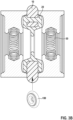
- Figure 1A 12 illustrates an embodiment of the sealing ring 100, which consists of an outer ring 10 made of PSU and an inner ring 20 made of a liquid silicone or liquid silicone rubber.
- Figure 1B shows a detailed representation of the outer ring 10 and the inner ring 20.
- the outer ring 10 has elongated holes 13 (perforations), which are used to claw the inner ring 20 made of LSR.
- the inner ring 20 in turn forms a groove 21 comprising a bottom 22 and two opposite walls extending from the bottom.
- the outer ring 2 or 3 advantageously has webs which extend from one wall 23 of the groove 21 to the other wall 23 of the groove 21 . These webs 24 pass through the respective elongated holes of the outer ring 10 and thus ensure a positive connection between the inner ring 20 and the outer ring 10.
- the outer ring 10 serves in particular as a stop for mounting the electrical contacts 30. Due to the PSU used, a particularly good connection to the epoxy resin is possible, which is used in the course of manufacturing the header and thus contributes to the electrical insulation above the PSU core.
- the outer ring serves as a guide for the wiring strips between the electrical contacts 30, for example an 8-pin module, for the feedthrough to the interior of the housing. This supports the process of welding the wiring strips to the electrical contact 30. A potential isolation of the wiring strips is thus also implemented by design.
- FIG. 12 depicts a flow diagram of the manufacture of the sealing ring 100. This manufacture falls outside the scope of the invention and is for illustration only.
- the PSU core or outer ring 10 is provided by an injection molding process. If necessary, the outer ring 10 is pretreated by vibratory grinding (trowalizing) or by cleaning. The outer ring is preferably additionally plasma-processed or primed (treatment with an adhesion promoter) for better adhesion of the LSR 20 . LSR is then injected around the outer ring 10, the LSR then the inner ring 20 forms. If the outer ring 10 has elongated holes 13, these are filled by the LSR, which results in an inner ring 20 with a groove 21 and webs 24, with the webs 24 then reaching through the respective elongated holes 13, and a form-fitting connection between the outer ring 10 and the inner ring 20 arises.
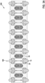
- FIG. 3 shows schematic views of a contact socket 200 according to the invention.
- the contact socket has a multiplicity of electrical contacts 30, in particular spring contacts, between which a sealing ring 10 is arranged in each case.
- the interior of the contact socket 200 has a cavity, in particular a cylindrical cavity, which is designed to accommodate a plug of an electrode line.
- the electrical contacts 30 serve to conduct a current or electrical impulse between the plug of the electrode line and the current-supplying or current-detecting components of an implantable device (for example ICD), which are accommodated in the housing of the device.
- the electrical contacts 30 are connected to the interior of the housing in particular via wiring straps.
- other shore hardnesses of the LSR Silastic product family are also suitable, e.g. 30, 50 or 60.
- the tempering temperature depends in particular on the material of the core, in particular on its melting temperature or glass transition temperature. In the case of a PSU core 10, it is annealed at a temperature of about 150°C for 12 hours. In the case of a PEEK core 10, higher temperatures can be used.
- liquid silicones from the Silpuran 6600 product family with different Shore hardnesses between 40 and 60 can be used.
Landscapes
- Engineering & Computer Science (AREA)
- General Engineering & Computer Science (AREA)
- Mechanical Engineering (AREA)
- Health & Medical Sciences (AREA)
- Animal Behavior & Ethology (AREA)
- Life Sciences & Earth Sciences (AREA)
- Radiology & Medical Imaging (AREA)
- General Health & Medical Sciences (AREA)
- Public Health (AREA)
- Veterinary Medicine (AREA)
- Nuclear Medicine, Radiotherapy & Molecular Imaging (AREA)
- Biomedical Technology (AREA)
- Materials For Medical Uses (AREA)
- Electrotherapy Devices (AREA)
- Compositions Of Macromolecular Compounds (AREA)
Claims (8)
- Douille de contact (200) destiné à un appareil médical implantable, comprenant une multiplicité de contacts électriques et au moins une bague d'étanchéité (100) ; chaque contact électrique de la multiplicité de contacts électriques présentant :- un boitier du contact électrique respectif ;la bague d'étanchéité présentant- une bague extérieure (10), laquelle comprend une matière plastique thermoplastique de performance élevée à base d'un poly aryle et un polymère à cristaux liquides, ou est essentiellement constituée, où le poly aryle est choisi parmi un poly aryle éther sulfone, une poly aryle éther cétone et un poly phénylène sulfure, et- une bague intérieure (20), laquelle comprend un silicone liquide ou un poly uréthane, ou en est essentiellement constituée,dans lequel la bague intérieure (20) et la bague extérieure (10) sont disposées en complémentarité des formes l'une par rapport à l'autre, et l'au moins une bague d'étanchéité (100) est disposée entre deux contacts électriques parmi la multiplicité de contacts électriques,caractérisée en ce quela bague extérieure (10) présente un diamètre extérieur plus grand que le diamètre extérieur du boitier respectif de chacun des deux contacts électriques voisins, et la bague intérieure (20) présente un diamètre extérieur plus petit que le diamètre extérieur du boitier respectif de chacun des deux contacts électriques voisins.
- Douille de contact (200) selon la revendication 1, caractérisée en ce que la bague intérieure (20) forme au moins une rainure (21), où la rainure (21) présente un fond (22) et deux bords (23) latéraux opposés qui s'étendent à partir du fond (22), et la bague extérieure (10) s'insère par complémentarité des formes dans la rainure (22).
- Douille de contact (200) selon la revendication 2, caractérisée en ce que la bague extérieure (10) présente au moins un passage (13), notamment un trou oblong, et la bague intérieure (20) présente au moins une tige (24) qui s'étend d'un côté (23) de la rainure (21) jusqu'à l'autre côté (23) de la rainure (21), et l'au moins une tige (24) passe à travers l'au moins un passage (13).
- Douille de contact (200) selon l'une quelconque des revendications précédentes, caractérisée en ce que le silicone liquide est choisi à base d'un mélange à deux composants de dureté Shore quelconque qui est biocompatible.
- Douille de contact (200) selon l'une quelconque des revendications précédentes, caractérisée en ce que la bague extérieure (10) est moulée par injection.
- Douille de contact (200) selon l'une quelconque des revendications précédentes, caractérisée en ce que la bague intérieure (20) et la bague extérieure (10) sont moulées par injection.
- Appareil implantable comprenant une douille de contact (200) selon l'une quelconque des revendications 1 à 6.
- Appareil implantable selon la revendication 7, l'appareil implantable étant conçu sous forme d'un défibrillateur cardioverteur implantable ou d'un stimulateur de moelle épinière implantable.
Applications Claiming Priority (1)
| Application Number | Priority Date | Filing Date | Title |
|---|---|---|---|
| EP18194056.0A EP3623005A1 (fr) | 2018-09-12 | 2018-09-12 | Bague d'étanchéité de polysulfone et silicone liquide |
Publications (2)
| Publication Number | Publication Date |
|---|---|
| EP3623007A1 EP3623007A1 (fr) | 2020-03-18 |
| EP3623007B1 true EP3623007B1 (fr) | 2023-06-21 |
Family
ID=63579075
Family Applications (2)
| Application Number | Title | Priority Date | Filing Date |
|---|---|---|---|
| EP18194056.0A Withdrawn EP3623005A1 (fr) | 2018-09-12 | 2018-09-12 | Bague d'étanchéité de polysulfone et silicone liquide |
| EP19195190.4A Active EP3623007B1 (fr) | 2018-09-12 | 2019-09-03 | Prise de contact |
Family Applications Before (1)
| Application Number | Title | Priority Date | Filing Date |
|---|---|---|---|
| EP18194056.0A Withdrawn EP3623005A1 (fr) | 2018-09-12 | 2018-09-12 | Bague d'étanchéité de polysulfone et silicone liquide |
Country Status (3)
| Country | Link |
|---|---|
| US (2) | US11174942B2 (fr) |
| EP (2) | EP3623005A1 (fr) |
| AU (1) | AU2019222869A1 (fr) |
Families Citing this family (1)
| Publication number | Priority date | Publication date | Assignee | Title |
|---|---|---|---|---|
| US12244091B2 (en) * | 2022-06-14 | 2025-03-04 | Aptiv Technologies AG | Electrical connector having a seal with a secondary terminal locking mechanism |
Family Cites Families (15)
| Publication number | Priority date | Publication date | Assignee | Title |
|---|---|---|---|---|
| JP2001502191A (ja) | 1996-02-27 | 2001-02-20 | インジェクタイムド・インコーポレーテッド | 皮下注射針の針先ガード |
| US7231253B2 (en) * | 1997-08-01 | 2007-06-12 | Medtronic, Inc. | IMD connector header with grommet retainer |
| RU2179274C1 (ru) * | 2000-06-02 | 2002-02-10 | Красноярский государственный технический университет | Уплотнение подвижного соединения двух деталей |
| US7367973B2 (en) * | 2003-06-30 | 2008-05-06 | Intuitive Surgical, Inc. | Electro-surgical instrument with replaceable end-effectors and inhibited surface conduction |
| US6895276B2 (en) * | 2002-02-28 | 2005-05-17 | Medtronic, Inc. | In-line lead header for an implantable medical device |
| US7299095B1 (en) * | 2003-12-17 | 2007-11-20 | Pacesetter, Inc. | Electrical contact assembly |
| US7711428B2 (en) | 2007-01-18 | 2010-05-04 | Medtronic, Inc. | Hermetic lead connector assembly |
| US7537474B2 (en) | 2007-07-12 | 2009-05-26 | Medtronic, Inc. | Lead receptacle and pin frame assembly |
| US8167660B2 (en) | 2009-09-04 | 2012-05-01 | Bal Seal Engineering, Inc. | Connector assemblies for use with implantable medical devices |
| US8751002B2 (en) | 2010-01-28 | 2014-06-10 | Medtronic, Inc. | Lead connector with glass braze |
| US8666494B2 (en) * | 2010-04-29 | 2014-03-04 | Donatelle Plastics, Inc. | Header for implantable pulse generator and method of making same |
| EP2740516A3 (fr) * | 2012-12-04 | 2014-07-23 | BIOTRONIK SE & Co. KG | Procédé de fabrication d'un module d'alésage de prise multipôles et module d'alésage de prise ainsi fabriqué |
| US9233239B2 (en) | 2013-07-11 | 2016-01-12 | Biotronik Se & Co. Kg | Spring contact component, plug contact socket, and contact socket component |
| US9907965B2 (en) | 2014-12-30 | 2018-03-06 | Medtronic, Inc. | Implantable medical devices with header structures including conductive paths that facilitate the interconnection of feedthrough conductors to electrical connectors |
| CN205350358U (zh) * | 2016-03-01 | 2016-06-29 | 青岛睿辰密封科技有限公司 | 一种耐高压带v形抗压环组合密封 |
-
2018
- 2018-09-12 EP EP18194056.0A patent/EP3623005A1/fr not_active Withdrawn
-
2019
- 2019-08-28 AU AU2019222869A patent/AU2019222869A1/en not_active Abandoned
- 2019-09-03 EP EP19195190.4A patent/EP3623007B1/fr active Active
- 2019-09-12 US US16/568,553 patent/US11174942B2/en active Active
-
2021
- 2021-10-13 US US17/500,371 patent/US11808358B2/en active Active
Also Published As
| Publication number | Publication date |
|---|---|
| EP3623005A1 (fr) | 2020-03-18 |
| US11808358B2 (en) | 2023-11-07 |
| US20220034405A1 (en) | 2022-02-03 |
| US11174942B2 (en) | 2021-11-16 |
| EP3623007A1 (fr) | 2020-03-18 |
| AU2019222869A1 (en) | 2020-03-26 |
| US20200080644A1 (en) | 2020-03-12 |
Similar Documents
| Publication | Publication Date | Title |
|---|---|---|
| EP2823856B1 (fr) | Composant de contact à ressort, douille de prise et composant de prise de contact | |
| EP2711046B1 (fr) | Ligne d'électrodes et élément de raccordement pour implants électromédicaux | |
| EP3784327B1 (fr) | Corps d'électrode d'un ensemble d'électrodes et ensemble d'électrodes de stimulation électrique et procédé de fabrication d'un ensemble d'électrodes | |
| DE69309764T2 (de) | Impulsgenerator mit Verbindungsöffnungen für Diagnose | |
| DE102018204610A1 (de) | Stecker zur Kontaktierung eines Kabels mit einem implantierbaren Gerät sowie Kabel mit Stecker und Herstellungsverfahren | |
| DE69411066T2 (de) | Elektrodenvorrichtung | |
| EP3213376B1 (fr) | Connecteur implantable | |
| DE102018124307A1 (de) | Stecker mit einem umspritzten, nicht drehbaren Steckeranschluss und vier Anschlüssen, insbesondere IS4-/DF4-Stecker | |
| EP3623007A1 (fr) | Bague d'étanchéité de la matière thermoplastique haute performance et du silicone liquide | |
| EP1974768A1 (fr) | Elément d'étanchéité et prise de contact pour implant médical | |
| EP2486954A2 (fr) | Passage de contact dans des composants électroniques | |
| EP0028201B1 (fr) | Elément de contrôle pour dispositifs haute tension et procédé de fabrication d'un élément de contrôle | |
| EP2388044A1 (fr) | Appareil électronique ou composant électrique | |
| DE102010015277A1 (de) | Elektrodenanordnung zur zumindest teilweisen Einbringung in einen Gehörkanal eines Menschen | |
| DE102021128427B4 (de) | Elektrode mit geschütztem Randbereich | |
| EP2918308A1 (fr) | Flexible isolant pour une conduite électrique destinée à l'application médicale et son procédé de fabrication | |
| DE3530269A1 (de) | Implantierbare elektrode zur herzstimulation | |
| WO2016189147A1 (fr) | Boîtier pour implant médical avec passage conducteur de courant | |
| WO2020182525A1 (fr) | Procédé de fabrication d'un implant médical | |
| DE102007011310A1 (de) | Medizinisches Implantat und Verfahren zur Herstellung desselben | |
| DE102021105989A1 (de) | Anschlussstecker für eine elektromedizinische Elektrode, einen Gegenstecker, elektromedizinische Elektrode und elektromedizinische Steckverbindung | |
| DE102021105988A1 (de) | Anschlussstecker für eine elektromedizinische Elektrode, einen Gegenstecker, elektromedizinische Elektrode und elektromedizinische Steckverbindung | |
| EP1529836B1 (fr) | Chambre de traitement de cellules | |
| DE69627736T2 (de) | Verfahren zur Herstellung einer Elektrodenanordnung für die Verwendung an einem Elektrodenkabel eines Herzschrittmachers | |
| DD149311A1 (de) | Vorrichtung fuer einen elektrodenanschluss an einen herzschrittmacher |
Legal Events
| Date | Code | Title | Description |
|---|---|---|---|
| PUAI | Public reference made under article 153(3) epc to a published international application that has entered the european phase |
Free format text: ORIGINAL CODE: 0009012 |
|
| STAA | Information on the status of an ep patent application or granted ep patent |
Free format text: STATUS: THE APPLICATION HAS BEEN PUBLISHED |
|
| AK | Designated contracting states |
Kind code of ref document: A1 Designated state(s): AL AT BE BG CH CY CZ DE DK EE ES FI FR GB GR HR HU IE IS IT LI LT LU LV MC MK MT NL NO PL PT RO RS SE SI SK SM TR |
|
| AX | Request for extension of the european patent |
Extension state: BA ME |
|
| STAA | Information on the status of an ep patent application or granted ep patent |
Free format text: STATUS: REQUEST FOR EXAMINATION WAS MADE |
|
| 17P | Request for examination filed |
Effective date: 20200914 |
|
| RBV | Designated contracting states (corrected) |
Designated state(s): AL AT BE BG CH CY CZ DE DK EE ES FI FR GB GR HR HU IE IS IT LI LT LU LV MC MK MT NL NO PL PT RO RS SE SI SK SM TR |
|
| STAA | Information on the status of an ep patent application or granted ep patent |
Free format text: STATUS: EXAMINATION IS IN PROGRESS |
|
| 17Q | First examination report despatched |
Effective date: 20211209 |
|
| GRAP | Despatch of communication of intention to grant a patent |
Free format text: ORIGINAL CODE: EPIDOSNIGR1 |
|
| STAA | Information on the status of an ep patent application or granted ep patent |
Free format text: STATUS: GRANT OF PATENT IS INTENDED |
|
| RIC1 | Information provided on ipc code assigned before grant |
Ipc: F16J 15/16 19680901ALN20230102BHEP Ipc: A61N 1/36 19680901ALN20230102BHEP Ipc: H01R 13/504 19800101ALN20230102BHEP Ipc: A61N 1/362 19850101ALN20230102BHEP Ipc: F16J 15/3272 20160101ALI20230102BHEP Ipc: A61N 1/375 19850101AFI20230102BHEP |
|
| RIC1 | Information provided on ipc code assigned before grant |
Ipc: F16J 15/16 19680901ALN20230109BHEP Ipc: A61N 1/36 19680901ALN20230109BHEP Ipc: H01R 13/504 19800101ALN20230109BHEP Ipc: A61N 1/362 19850101ALN20230109BHEP Ipc: F16J 15/3272 20160101ALI20230109BHEP Ipc: A61N 1/375 19850101AFI20230109BHEP |
|
| INTG | Intention to grant announced |
Effective date: 20230127 |
|
| GRAS | Grant fee paid |
Free format text: ORIGINAL CODE: EPIDOSNIGR3 |
|
| GRAA | (expected) grant |
Free format text: ORIGINAL CODE: 0009210 |
|
| STAA | Information on the status of an ep patent application or granted ep patent |
Free format text: STATUS: THE PATENT HAS BEEN GRANTED |
|
| AK | Designated contracting states |
Kind code of ref document: B1 Designated state(s): AL AT BE BG CH CY CZ DE DK EE ES FI FR GB GR HR HU IE IS IT LI LT LU LV MC MK MT NL NO PL PT RO RS SE SI SK SM TR |
|
| REG | Reference to a national code |
Ref country code: CH Ref legal event code: EP |
|
| REG | Reference to a national code |
Ref country code: DE Ref legal event code: R096 Ref document number: 502019008237 Country of ref document: DE |
|
| REG | Reference to a national code |
Ref country code: AT Ref legal event code: REF Ref document number: 1580473 Country of ref document: AT Kind code of ref document: T Effective date: 20230715 |
|
| P01 | Opt-out of the competence of the unified patent court (upc) registered |
Effective date: 20230612 |
|
| REG | Reference to a national code |
Ref country code: IE Ref legal event code: FG4D Free format text: LANGUAGE OF EP DOCUMENT: GERMAN |
|
| REG | Reference to a national code |
Ref country code: LT Ref legal event code: MG9D |
|
| REG | Reference to a national code |
Ref country code: NL Ref legal event code: MP Effective date: 20230621 |
|
| PG25 | Lapsed in a contracting state [announced via postgrant information from national office to epo] |
Ref country code: SE Free format text: LAPSE BECAUSE OF FAILURE TO SUBMIT A TRANSLATION OF THE DESCRIPTION OR TO PAY THE FEE WITHIN THE PRESCRIBED TIME-LIMIT Effective date: 20230621 Ref country code: NO Free format text: LAPSE BECAUSE OF FAILURE TO SUBMIT A TRANSLATION OF THE DESCRIPTION OR TO PAY THE FEE WITHIN THE PRESCRIBED TIME-LIMIT Effective date: 20230921 |
|
| PG25 | Lapsed in a contracting state [announced via postgrant information from national office to epo] |
Ref country code: RS Free format text: LAPSE BECAUSE OF FAILURE TO SUBMIT A TRANSLATION OF THE DESCRIPTION OR TO PAY THE FEE WITHIN THE PRESCRIBED TIME-LIMIT Effective date: 20230621 Ref country code: NL Free format text: LAPSE BECAUSE OF FAILURE TO SUBMIT A TRANSLATION OF THE DESCRIPTION OR TO PAY THE FEE WITHIN THE PRESCRIBED TIME-LIMIT Effective date: 20230621 Ref country code: LV Free format text: LAPSE BECAUSE OF FAILURE TO SUBMIT A TRANSLATION OF THE DESCRIPTION OR TO PAY THE FEE WITHIN THE PRESCRIBED TIME-LIMIT Effective date: 20230621 Ref country code: LT Free format text: LAPSE BECAUSE OF FAILURE TO SUBMIT A TRANSLATION OF THE DESCRIPTION OR TO PAY THE FEE WITHIN THE PRESCRIBED TIME-LIMIT Effective date: 20230621 Ref country code: HR Free format text: LAPSE BECAUSE OF FAILURE TO SUBMIT A TRANSLATION OF THE DESCRIPTION OR TO PAY THE FEE WITHIN THE PRESCRIBED TIME-LIMIT Effective date: 20230621 Ref country code: GR Free format text: LAPSE BECAUSE OF FAILURE TO SUBMIT A TRANSLATION OF THE DESCRIPTION OR TO PAY THE FEE WITHIN THE PRESCRIBED TIME-LIMIT Effective date: 20230922 |
|
| PG25 | Lapsed in a contracting state [announced via postgrant information from national office to epo] |
Ref country code: FI Free format text: LAPSE BECAUSE OF FAILURE TO SUBMIT A TRANSLATION OF THE DESCRIPTION OR TO PAY THE FEE WITHIN THE PRESCRIBED TIME-LIMIT Effective date: 20230621 |
|
| PG25 | Lapsed in a contracting state [announced via postgrant information from national office to epo] |
Ref country code: SK Free format text: LAPSE BECAUSE OF FAILURE TO SUBMIT A TRANSLATION OF THE DESCRIPTION OR TO PAY THE FEE WITHIN THE PRESCRIBED TIME-LIMIT Effective date: 20230621 |
|
| PG25 | Lapsed in a contracting state [announced via postgrant information from national office to epo] |
Ref country code: ES Free format text: LAPSE BECAUSE OF FAILURE TO SUBMIT A TRANSLATION OF THE DESCRIPTION OR TO PAY THE FEE WITHIN THE PRESCRIBED TIME-LIMIT Effective date: 20230621 |
|
| PG25 | Lapsed in a contracting state [announced via postgrant information from national office to epo] |
Ref country code: IS Free format text: LAPSE BECAUSE OF FAILURE TO SUBMIT A TRANSLATION OF THE DESCRIPTION OR TO PAY THE FEE WITHIN THE PRESCRIBED TIME-LIMIT Effective date: 20231021 |
|
| PG25 | Lapsed in a contracting state [announced via postgrant information from national office to epo] |
Ref country code: SM Free format text: LAPSE BECAUSE OF FAILURE TO SUBMIT A TRANSLATION OF THE DESCRIPTION OR TO PAY THE FEE WITHIN THE PRESCRIBED TIME-LIMIT Effective date: 20230621 Ref country code: SK Free format text: LAPSE BECAUSE OF FAILURE TO SUBMIT A TRANSLATION OF THE DESCRIPTION OR TO PAY THE FEE WITHIN THE PRESCRIBED TIME-LIMIT Effective date: 20230621 Ref country code: RO Free format text: LAPSE BECAUSE OF FAILURE TO SUBMIT A TRANSLATION OF THE DESCRIPTION OR TO PAY THE FEE WITHIN THE PRESCRIBED TIME-LIMIT Effective date: 20230621 Ref country code: PT Free format text: LAPSE BECAUSE OF FAILURE TO SUBMIT A TRANSLATION OF THE DESCRIPTION OR TO PAY THE FEE WITHIN THE PRESCRIBED TIME-LIMIT Effective date: 20231023 Ref country code: IS Free format text: LAPSE BECAUSE OF FAILURE TO SUBMIT A TRANSLATION OF THE DESCRIPTION OR TO PAY THE FEE WITHIN THE PRESCRIBED TIME-LIMIT Effective date: 20231021 Ref country code: ES Free format text: LAPSE BECAUSE OF FAILURE TO SUBMIT A TRANSLATION OF THE DESCRIPTION OR TO PAY THE FEE WITHIN THE PRESCRIBED TIME-LIMIT Effective date: 20230621 Ref country code: EE Free format text: LAPSE BECAUSE OF FAILURE TO SUBMIT A TRANSLATION OF THE DESCRIPTION OR TO PAY THE FEE WITHIN THE PRESCRIBED TIME-LIMIT Effective date: 20230621 Ref country code: CZ Free format text: LAPSE BECAUSE OF FAILURE TO SUBMIT A TRANSLATION OF THE DESCRIPTION OR TO PAY THE FEE WITHIN THE PRESCRIBED TIME-LIMIT Effective date: 20230621 |
|
| PG25 | Lapsed in a contracting state [announced via postgrant information from national office to epo] |
Ref country code: PL Free format text: LAPSE BECAUSE OF FAILURE TO SUBMIT A TRANSLATION OF THE DESCRIPTION OR TO PAY THE FEE WITHIN THE PRESCRIBED TIME-LIMIT Effective date: 20230621 |
|
| REG | Reference to a national code |
Ref country code: DE Ref legal event code: R097 Ref document number: 502019008237 Country of ref document: DE |
|
| PLBE | No opposition filed within time limit |
Free format text: ORIGINAL CODE: 0009261 |
|
| STAA | Information on the status of an ep patent application or granted ep patent |
Free format text: STATUS: NO OPPOSITION FILED WITHIN TIME LIMIT |
|
| PG25 | Lapsed in a contracting state [announced via postgrant information from national office to epo] |
Ref country code: DK Free format text: LAPSE BECAUSE OF FAILURE TO SUBMIT A TRANSLATION OF THE DESCRIPTION OR TO PAY THE FEE WITHIN THE PRESCRIBED TIME-LIMIT Effective date: 20230621 |
|
| REG | Reference to a national code |
Ref country code: CH Ref legal event code: PL |
|
| PG25 | Lapsed in a contracting state [announced via postgrant information from national office to epo] |
Ref country code: SI Free format text: LAPSE BECAUSE OF FAILURE TO SUBMIT A TRANSLATION OF THE DESCRIPTION OR TO PAY THE FEE WITHIN THE PRESCRIBED TIME-LIMIT Effective date: 20230621 |
|
| PG25 | Lapsed in a contracting state [announced via postgrant information from national office to epo] |
Ref country code: LU Free format text: LAPSE BECAUSE OF NON-PAYMENT OF DUE FEES Effective date: 20230903 |
|
| REG | Reference to a national code |
Ref country code: BE Ref legal event code: MM Effective date: 20230930 |
|
| 26N | No opposition filed |
Effective date: 20240322 |
|
| PG25 | Lapsed in a contracting state [announced via postgrant information from national office to epo] |
Ref country code: SI Free format text: LAPSE BECAUSE OF FAILURE TO SUBMIT A TRANSLATION OF THE DESCRIPTION OR TO PAY THE FEE WITHIN THE PRESCRIBED TIME-LIMIT Effective date: 20230621 Ref country code: LU Free format text: LAPSE BECAUSE OF NON-PAYMENT OF DUE FEES Effective date: 20230903 Ref country code: IT Free format text: LAPSE BECAUSE OF FAILURE TO SUBMIT A TRANSLATION OF THE DESCRIPTION OR TO PAY THE FEE WITHIN THE PRESCRIBED TIME-LIMIT Effective date: 20230621 Ref country code: MC Free format text: LAPSE BECAUSE OF FAILURE TO SUBMIT A TRANSLATION OF THE DESCRIPTION OR TO PAY THE FEE WITHIN THE PRESCRIBED TIME-LIMIT Effective date: 20230621 |
|
| REG | Reference to a national code |
Ref country code: IE Ref legal event code: MM4A |
|
| PG25 | Lapsed in a contracting state [announced via postgrant information from national office to epo] |
Ref country code: IE Free format text: LAPSE BECAUSE OF NON-PAYMENT OF DUE FEES Effective date: 20230903 |
|
| PG25 | Lapsed in a contracting state [announced via postgrant information from national office to epo] |
Ref country code: CH Free format text: LAPSE BECAUSE OF NON-PAYMENT OF DUE FEES Effective date: 20230930 |
|
| PG25 | Lapsed in a contracting state [announced via postgrant information from national office to epo] |
Ref country code: IE Free format text: LAPSE BECAUSE OF NON-PAYMENT OF DUE FEES Effective date: 20230903 Ref country code: CH Free format text: LAPSE BECAUSE OF NON-PAYMENT OF DUE FEES Effective date: 20230930 |
|
| PG25 | Lapsed in a contracting state [announced via postgrant information from national office to epo] |
Ref country code: BE Free format text: LAPSE BECAUSE OF NON-PAYMENT OF DUE FEES Effective date: 20230930 |
|
| PG25 | Lapsed in a contracting state [announced via postgrant information from national office to epo] |
Ref country code: BG Free format text: LAPSE BECAUSE OF FAILURE TO SUBMIT A TRANSLATION OF THE DESCRIPTION OR TO PAY THE FEE WITHIN THE PRESCRIBED TIME-LIMIT Effective date: 20230621 |
|
| PG25 | Lapsed in a contracting state [announced via postgrant information from national office to epo] |
Ref country code: BG Free format text: LAPSE BECAUSE OF FAILURE TO SUBMIT A TRANSLATION OF THE DESCRIPTION OR TO PAY THE FEE WITHIN THE PRESCRIBED TIME-LIMIT Effective date: 20230621 |
|
| PG25 | Lapsed in a contracting state [announced via postgrant information from national office to epo] |
Ref country code: CY Free format text: LAPSE BECAUSE OF FAILURE TO SUBMIT A TRANSLATION OF THE DESCRIPTION OR TO PAY THE FEE WITHIN THE PRESCRIBED TIME-LIMIT; INVALID AB INITIO Effective date: 20190903 |
|
| PG25 | Lapsed in a contracting state [announced via postgrant information from national office to epo] |
Ref country code: HU Free format text: LAPSE BECAUSE OF FAILURE TO SUBMIT A TRANSLATION OF THE DESCRIPTION OR TO PAY THE FEE WITHIN THE PRESCRIBED TIME-LIMIT; INVALID AB INITIO Effective date: 20190903 |
|
| PGFP | Annual fee paid to national office [announced via postgrant information from national office to epo] |
Ref country code: DE Payment date: 20250919 Year of fee payment: 7 |
|
| PGFP | Annual fee paid to national office [announced via postgrant information from national office to epo] |
Ref country code: GB Payment date: 20250923 Year of fee payment: 7 |
|
| PGFP | Annual fee paid to national office [announced via postgrant information from national office to epo] |
Ref country code: FR Payment date: 20250926 Year of fee payment: 7 |
|
| REG | Reference to a national code |
Ref country code: AT Ref legal event code: MM01 Ref document number: 1580473 Country of ref document: AT Kind code of ref document: T Effective date: 20240903 |
|
| PG25 | Lapsed in a contracting state [announced via postgrant information from national office to epo] |
Ref country code: TR Free format text: LAPSE BECAUSE OF FAILURE TO SUBMIT A TRANSLATION OF THE DESCRIPTION OR TO PAY THE FEE WITHIN THE PRESCRIBED TIME-LIMIT Effective date: 20230621 |
|
| PG25 | Lapsed in a contracting state [announced via postgrant information from national office to epo] |
Ref country code: AT Free format text: LAPSE BECAUSE OF NON-PAYMENT OF DUE FEES Effective date: 20240903 |
|
| PGFP | Annual fee paid to national office [announced via postgrant information from national office to epo] |
Ref country code: AT Payment date: 20260410 Year of fee payment: 5 |